EP3160585B1 - Charged particle beam therapy and magnetic resonance imaging - Google Patents
Charged particle beam therapy and magnetic resonance imaging Download PDFInfo
- Publication number
- EP3160585B1 EP3160585B1 EP15729854.8A EP15729854A EP3160585B1 EP 3160585 B1 EP3160585 B1 EP 3160585B1 EP 15729854 A EP15729854 A EP 15729854A EP 3160585 B1 EP3160585 B1 EP 3160585B1
- Authority
- EP
- European Patent Office
- Prior art keywords
- active compensation
- compensation coil
- magnet
- particle beam
- coil
- Prior art date
- Legal status (The legal status is an assumption and is not a legal conclusion. Google has not performed a legal analysis and makes no representation as to the accuracy of the status listed.)
- Not-in-force
Links
- 239000002245 particle Substances 0.000 title claims description 85
- 238000002595 magnetic resonance imaging Methods 0.000 title claims description 45
- 238000002560 therapeutic procedure Methods 0.000 title description 7
- 230000005291 magnetic effect Effects 0.000 claims description 79
- 238000005452 bending Methods 0.000 claims description 76
- 238000003384 imaging method Methods 0.000 claims description 49
- 238000004804 winding Methods 0.000 claims description 43
- 239000002184 metal Substances 0.000 claims description 16
- 229910052751 metal Inorganic materials 0.000 claims description 16
- 238000012937 correction Methods 0.000 claims description 7
- 238000002661 proton therapy Methods 0.000 description 16
- 238000013461 design Methods 0.000 description 13
- 238000009826 distribution Methods 0.000 description 12
- 238000000034 method Methods 0.000 description 11
- 239000000463 material Substances 0.000 description 5
- RYGMFSIKBFXOCR-UHFFFAOYSA-N Copper Chemical compound [Cu] RYGMFSIKBFXOCR-UHFFFAOYSA-N 0.000 description 4
- CWYNVVGOOAEACU-UHFFFAOYSA-N Fe2+ Chemical compound [Fe+2] CWYNVVGOOAEACU-UHFFFAOYSA-N 0.000 description 4
- 238000001816 cooling Methods 0.000 description 4
- 230000000694 effects Effects 0.000 description 4
- 230000005294 ferromagnetic effect Effects 0.000 description 4
- 230000006870 function Effects 0.000 description 4
- 238000011282 treatment Methods 0.000 description 4
- 230000008859 change Effects 0.000 description 3
- 239000004020 conductor Substances 0.000 description 3
- 229910052802 copper Inorganic materials 0.000 description 3
- 239000010949 copper Substances 0.000 description 3
- 230000003993 interaction Effects 0.000 description 3
- 230000005855 radiation Effects 0.000 description 3
- 230000003068 static effect Effects 0.000 description 3
- XLYOFNOQVPJJNP-UHFFFAOYSA-N water Substances O XLYOFNOQVPJJNP-UHFFFAOYSA-N 0.000 description 3
- XEEYBQQBJWHFJM-UHFFFAOYSA-N Iron Chemical compound [Fe] XEEYBQQBJWHFJM-UHFFFAOYSA-N 0.000 description 2
- 206010028980 Neoplasm Diseases 0.000 description 2
- 238000005457 optimization Methods 0.000 description 2
- 238000001959 radiotherapy Methods 0.000 description 2
- 210000003484 anatomy Anatomy 0.000 description 1
- 230000008901 benefit Effects 0.000 description 1
- 201000011510 cancer Diseases 0.000 description 1
- 239000002826 coolant Substances 0.000 description 1
- 230000007423 decrease Effects 0.000 description 1
- 230000003247 decreasing effect Effects 0.000 description 1
- 230000001419 dependent effect Effects 0.000 description 1
- 238000006073 displacement reaction Methods 0.000 description 1
- 239000003302 ferromagnetic material Substances 0.000 description 1
- 229910052742 iron Inorganic materials 0.000 description 1
- 238000004519 manufacturing process Methods 0.000 description 1
- 238000005259 measurement Methods 0.000 description 1
- 230000007246 mechanism Effects 0.000 description 1
- 210000000056 organ Anatomy 0.000 description 1
- 230000008569 process Effects 0.000 description 1
- 238000012545 processing Methods 0.000 description 1
- 238000004088 simulation Methods 0.000 description 1
Images


Classifications
-
- A—HUMAN NECESSITIES
- A61—MEDICAL OR VETERINARY SCIENCE; HYGIENE
- A61B—DIAGNOSIS; SURGERY; IDENTIFICATION
- A61B5/00—Measuring for diagnostic purposes; Identification of persons
- A61B5/05—Detecting, measuring or recording for diagnosis by means of electric currents or magnetic fields; Measuring using microwaves or radio waves
- A61B5/055—Detecting, measuring or recording for diagnosis by means of electric currents or magnetic fields; Measuring using microwaves or radio waves involving electronic [EMR] or nuclear [NMR] magnetic resonance, e.g. magnetic resonance imaging
-
- A—HUMAN NECESSITIES
- A61—MEDICAL OR VETERINARY SCIENCE; HYGIENE
- A61N—ELECTROTHERAPY; MAGNETOTHERAPY; RADIATION THERAPY; ULTRASOUND THERAPY
- A61N5/00—Radiation therapy
- A61N5/10—X-ray therapy; Gamma-ray therapy; Particle-irradiation therapy
- A61N5/1048—Monitoring, verifying, controlling systems and methods
- A61N5/1049—Monitoring, verifying, controlling systems and methods for verifying the position of the patient with respect to the radiation beam
-
- A—HUMAN NECESSITIES
- A61—MEDICAL OR VETERINARY SCIENCE; HYGIENE
- A61N—ELECTROTHERAPY; MAGNETOTHERAPY; RADIATION THERAPY; ULTRASOUND THERAPY
- A61N5/00—Radiation therapy
- A61N5/10—X-ray therapy; Gamma-ray therapy; Particle-irradiation therapy
- A61N5/1077—Beam delivery systems
- A61N5/1081—Rotating beam systems with a specific mechanical construction, e.g. gantries
-
- G—PHYSICS
- G01—MEASURING; TESTING
- G01R—MEASURING ELECTRIC VARIABLES; MEASURING MAGNETIC VARIABLES
- G01R33/00—Arrangements or instruments for measuring magnetic variables
- G01R33/20—Arrangements or instruments for measuring magnetic variables involving magnetic resonance
- G01R33/28—Details of apparatus provided for in groups G01R33/44 - G01R33/64
- G01R33/38—Systems for generation, homogenisation or stabilisation of the main or gradient magnetic field
- G01R33/3806—Open magnet assemblies for improved access to the sample, e.g. C-type or U-type magnets
-
- G—PHYSICS
- G01—MEASURING; TESTING
- G01R—MEASURING ELECTRIC VARIABLES; MEASURING MAGNETIC VARIABLES
- G01R33/00—Arrangements or instruments for measuring magnetic variables
- G01R33/20—Arrangements or instruments for measuring magnetic variables involving magnetic resonance
- G01R33/28—Details of apparatus provided for in groups G01R33/44 - G01R33/64
- G01R33/38—Systems for generation, homogenisation or stabilisation of the main or gradient magnetic field
- G01R33/387—Compensation of inhomogeneities
- G01R33/3875—Compensation of inhomogeneities using correction coil assemblies, e.g. active shimming
-
- G—PHYSICS
- G01—MEASURING; TESTING
- G01R—MEASURING ELECTRIC VARIABLES; MEASURING MAGNETIC VARIABLES
- G01R33/00—Arrangements or instruments for measuring magnetic variables
- G01R33/20—Arrangements or instruments for measuring magnetic variables involving magnetic resonance
- G01R33/44—Arrangements or instruments for measuring magnetic variables involving magnetic resonance using nuclear magnetic resonance [NMR]
- G01R33/48—NMR imaging systems
- G01R33/4808—Multimodal MR, e.g. MR combined with positron emission tomography [PET], MR combined with ultrasound or MR combined with computed tomography [CT]
-
- A—HUMAN NECESSITIES
- A61—MEDICAL OR VETERINARY SCIENCE; HYGIENE
- A61N—ELECTROTHERAPY; MAGNETOTHERAPY; RADIATION THERAPY; ULTRASOUND THERAPY
- A61N5/00—Radiation therapy
- A61N5/10—X-ray therapy; Gamma-ray therapy; Particle-irradiation therapy
- A61N5/1048—Monitoring, verifying, controlling systems and methods
- A61N5/1049—Monitoring, verifying, controlling systems and methods for verifying the position of the patient with respect to the radiation beam
- A61N2005/1055—Monitoring, verifying, controlling systems and methods for verifying the position of the patient with respect to the radiation beam using magnetic resonance imaging [MRI]
-
- A—HUMAN NECESSITIES
- A61—MEDICAL OR VETERINARY SCIENCE; HYGIENE
- A61N—ELECTROTHERAPY; MAGNETOTHERAPY; RADIATION THERAPY; ULTRASOUND THERAPY
- A61N5/00—Radiation therapy
- A61N5/10—X-ray therapy; Gamma-ray therapy; Particle-irradiation therapy
- A61N2005/1085—X-ray therapy; Gamma-ray therapy; Particle-irradiation therapy characterised by the type of particles applied to the patient
- A61N2005/1087—Ions; Protons
Definitions
- the invention relates to the area of guiding of charged particles to a target zone within a subject of interest, whereby the particles are guided using magnetic resonance imaging.
- an energetic charged particle beam is directed at a target zone of a subject.
- the primary mechanism for interaction of a beam comprising charged particles with matter is through the Coulomb force.
- the cross section for Coulomb collisions increases as the relative velocity of two particles decreases.
- charged particle beam therapy allows very precise delivery of high dose to a target zone, e.g. to a tumor target, while minimizing the total dose to a subject of interest.
- a target zone e.g. to a tumor target
- even small movements of the subject of interest e.g. of anatomical structures in the path of the beam or a displacement of the target zone, can lead to significant deviations of the delivered dose from the original dose plan. Therefore, it is desirable to use real-time imaging to track the subject of interest and to adapt the beam to the motion of the subject of interest including the motion of organs of the subject of interest.
- the accuracy of charged particle beam therapy can be significantly improved by real-time guidance based on magnetic resonance (MR) imaging.
- MR magnetic resonance
- charged particle beam therapy different kinds of charged particles can be used for treatment of the subject of interest, e.g. as a cancer treatment. Accordingly, a source of charged particles is required and a beam path to direct the charged particle beam into the subject of interest.
- charged particle beam therapy is Proton Therapy (PT), where protons are directed into the subject of interest.
- PT Proton Therapy
- An example of a combined MR-Proton therapy apparatus is described in EP 2 379 172 B1 .
- MRI magnetic resonance imaging
- a static magnetic field is used by Magnetic Resonance Imaging (MRI) scanners to align the nuclear spins of atoms as part of the procedure for producing images within the body of the subject of interest.
- MRI Magnetic Resonance Imaging
- RF Radio Frequency
- the transmitter and receiver coils can also be integrated into a single transceiver coil. It is understood that the use of the term transceiver coil also refers to systems where separate transmitter and receiver coils are used.
- the subject of interest is located within a magnetic resonance imaging (MRI) system, and a proton source is provided together with a gantry, which directs the protons into the subject of interest.
- the gantry is rotatable around a z-axis of the MRI system, i.e. around the z-axis of a main magnet of the MRI system, to direct the radiation towards the subject of interest in a direction substantially perpendicular to the z-axis, which is achieved using at least one bending magnet, also referred to as dipole magnet, in the gantry.
- This setup brings the at least one bending magnet of the proton therapy system in close proximity to the main magnet of the MRI system.
- the bending magnet generates a strong dipole field, which can have a field strength of e.g. ⁇ 1.5T, in a large aperture and potentially creates a strong stray-field in the direction perpendicular to the bending plane. Since this stray field drops off rapidly with distance from the dipole magnet, it also has components in other directions, notably along the direction of the MRI magnet's main field, i.e. in the direction of the z-axis. This field will cause image distortion and other artifacts.
- a static compensation of the PT field at the MRI system e.g.
- the strength of the field of the dipole magnet has to be modulated along with modulation of the energy of the charged particles.
- the energy of the charged particles is adapted to move the Bragg zone along the beam direction, e.g. charged particles with increased energy enter further into the subject of interest than charged particles with lower energy.
- the strength of the external field of the bending magnet will thus also be variable.
- a method for correcting a magnetic field of an MRI radiotherapy apparatus comprising a magnetic resonance imaging system and a radiation therapy system.
- the MRI system includes a magnet for generating the magnetic field within an imaging zone.
- the magnet generates a magnetic field with a zero crossing outside of the imaging zone.
- the medical apparatus further comprises a gantry configured for rotating a ferromagnetic component about a rotational axis.
- the method comprises the step of installing a magnetic correcting element located on a radial path perpendicular to the rotational axis.
- the magnetic correcting element is positioned on the radial path such that change in the magnetic field within the imaging zone due to the ferromagnetic component is reduced.
- the method further comprises repeatedly: measuring the magnetic field within the imaging zone; determining the change in the magnetic field in the imaging zone; and adjusting the position of the magnetic correcting element along the radial path if the change in the magnetic field is above a predetermined threshold.
- post-published WO 2014/121991 A1 refers to a medical apparatus comprising a magnetic resonance imaging system; magnetic compensation coils for compensating for magnetic inhomogeneities within the imaging zone; a gantry operable for rotating about the imaging zone; a position sensor for measuring the angular position and the angular velocity of the gantry; at least one magnetic field distorting component in the gantry, a memory storing machine executable instructions and field correction data.
- the instructions cause a processor to: receive the position and angular velocity data from the position sensor; determine coil control commands for controlling the magnetic compensation coils using the field correction data, the position data and the angular velocity data; control the magnetic compensation coils to compensate for magnetic inhomogeneities within the imaging zone using the coil control commands; and acquire the magnetic resonance data.
- a medical apparatus comprising a magnetic resonance imaging system for acquiring magnetic resonance data from an imaging volume covering at least partially a subject of interest, wherein the magnetic resonance imaging system comprises a main magnet for generating a magnetic field within the imaging volume, a particle beam apparatus having a particle beam line for providing a particle beam of charged particles, including a gantry configured for rotating around a rotational axis, which is arranged in the longitudinal direction of the main magnet, wherein the gantry comprises at least one bending magnet for directing the particle beam to an irradiation volume within the imaging volume, an active compensation coil, which is arranged to substantially surround at least the imaging volume and which is provided in proximity to an outer surface of the main magnet, and a control unit for controlling the active compensation coil for canceling a stray field caused by the at least one bending magnet within the imaging volume at least in the longitudinal direction of the main magnet.
- a shielding method for use in a medical apparatus comprises the steps of providing a magnetic resonance imaging system for acquiring magnetic resonance data from an imaging volume covering at least partially a subject of interest, wherein the magnetic resonance imaging system comprises a main magnet for generating a magnetic field within the imaging volume, providing a particle beam apparatus having a particle beam line for a particle beam of charged particles, including a gantry configured for rotating around a rotational axis, which is arranged in the longitudinal direction of the main magnet, wherein the gantry comprises at least one bending magnet for directing the particle beam to an irradiation volume within the imaging volume, providing an active compensation coil, which is arranged to substantially surround at least the imaging volume and which is provided in proximity to an outer surface of the main magnet, and controlling the active compensation coil for canceling a stray field caused by the at least one bending magnet within the imaging volume at least in the longitudinal direction of the main magnet.
- the active compensation coil actively cancels the z-component of the stray field of the at least one bending magnet across the field of view or imaging volume of the MR magnet.
- the stray field of the at least one bending magnet of the particle beam apparatus is actively compensated in such a way that its component along a main field direction of the MR magnet, i.e. a longitudinal direction or z-axis of the MR magnet, is either homogeneous or zero over the imaging volume of the MR system.
- This is preferably applied for all rotational positions of the gantry of the particle beam apparatus and for all strengths of the magnetic field of the at least one bending magnet.
- the bending magnet is also referred to as dipole magnet.
- Shielding of the at least one bending magnet itself i.e. shielding the magnetic field at the source is not easy due to the great strength of this magnetic field.
- Passively shielding with ferromagnetic material would be problematic, because this shielding material would also be exposed to the stray field of the MRI magnet and thereby create additional field inhomogeneity across the imaging volume.
- the strength of the magnetic field of the at least one bending magnet and hence also its stray field is not constant in time, but varies with the energy of the charged particles. As most treatment procedures involve a modulation of the energy of the charged particles in order to move the Bragg peak in beam direction, a static compensation is not suitable to cancel the effect of the magnetic field of the at least one bending magnet.
- Active compensation of the magnetic field of the at least one bending magnet is most efficient when the active compensation coil is as close as possible to the volume where the compensating field is required. Consequently, it is preferred to provide the active compensation coil as far away as possible from the at least one bending magnet. Therefore, it is preferred that the active compensation coil has its windings distributed over a cylindrical surface located just outside the cylindrical outer surface of the magnet, or outside the cylindrical outer surface of a cryostat of the main magnet.
- the magnet of the MRI does not have any protrusions, so that the active compensation coil can be located in close proximity to the main magnet and as far away from the at least one bending magnet as possible.
- protrusions are provided e.g. for cryogenic or vacuum ports, magnet support attachments, magnet feet, or other components.
- the gantry is provided to direct the beam of charged particles to the subject of interest with an angle perpendicular to the z-axis of the main magnet. Accordingly, the passage of the charged particles through the subject of interest can be limited to a minimum, thereby reducing a dose for the subject of interest.
- the active compensation coil is provided with a suitable shape and current distribution, so that is generates essentially the same magnetic field pattern as the at least one bending magnet, but with opposite polarity. This is achieved by a respective design of the active compensation coil.
- the active compensation coil has a winding distribution, so that with a control of the current of the active compensating coil the resulting magnetic field, i.e. the magnetic field of the at least one bending magnet together with the magnetic field of the active compensation coil, has a uniform z-component over the entire field of view of the MR magnet, i.e. the imaging volume.
- the transverse components of the total field of the at least one bending magnet and the active compensation coil need not be zero. As long as the total transverse field is small enough that the vector sum of the transverse field and the main MRI magnet field is not significantly different from the magnetic field of the MR magnet, the imaging process of the MRI system will not be affected by the transverse field.
- a preferred choice for the strength of the resulting z-component of the magnetic field of the at least one bending magnet of the particle beam apparatus and the active compensation coil is zero. Even with this design restriction, a high number of solutions for the current distribution in the active compensating coil can be obtained, i.e. the design of the active compensation coils is essentially not limited by this specification.
- the special case that also the transverse components of the net field of the at least one bending magnet and the compensation coil be zero is attractive because it would eliminate other possible interactions between the magnetic resonance imaging system and the particle beam apparatus. Nevertheless, this implementation requires a powerful design of the active compensation coil, which would result in a complex design compared to an active compensation coil for cancelling essentially the overall z-component of the magnetic field.
- a current pattern for the active compensation coil is be designed by first calculating or measuring a field map of the at least one bending magnet at the location of the imaging volume of the MR magnet. These field values can then be used as field targets for a coil optimization program using the stream function method. This is similar to what is normally used to design MR gradient coils. The cost function in the optimization can then be the total dissipation in the active compensation coil.
- the resulting current pattern is preferably discretized into windings each carrying the same operating current.
- the active compensation coil also compensates the fields of other sources of magnetic fields of the particle beam apparatus.
- the active compensation coil also compensates the fields of other sources of magnetic fields, which scale with the operating current in the at least one bending magnet.
- the a particle beam apparatus is a Proton Therapy (PT) apparatus for directing a beam of protons to the subject of interest.
- PT apparatus are known in the Art and do not have to be discussed in detail.
- the active compensation coil is fixed to the gantry and rotatable together with the gantry around the rotational axis.
- the active compensation coil With the active compensation coil fixed to the gantry, the active compensation coil can easily rotate with the gantry and the at least one bending magnet, so that magnetic fields generated by the at least one bending magnet and magnetic files for compensation thereof, which are generated by the active compensation coil, rotate together . This facilitates compensation of the rotating magnetic fields.
- the active compensation coil is rotatable around the rotational axis of the gantry, but the rotation of the active compensation coil is controlled independently from the rotation of the gantry. Accordingly, the active compensation coil can be easily added to existing medical apparatus. It can also be added easily existing particle beam apparatus. The design of the existing apparatus does not have to be changed.
- the active compensation coil is fixed to an outlet section of the gantry.
- the outlet section of the gantry refers to the part of the gantry, where the particle beam leaves the gantry to enter the subject of interest.
- Active compensation of the magnetic field of the at least one bending magnet is most efficient when the active compensation coil is as close as possible to the volume where the compensating field is required. Consequently, it is preferred to provide the active compensation coil as far away as possible from the at least one bending magnet, i.e. the active compensation coil is fixed to the outlet section, which is close to the main magnet.
- the active compensation coil comprises a cylindrical support structure and a set of windings arranged at the support structure for carrying a compensation current.
- the support structure and the windings are preferably made of non-ferrous materials to avoid influences on the magnetic field inside the main magnet, in particular in the imaging volume.
- the windings are made of copper.
- the windings of the active compensation coil can be placed on an outer or inner surface of the support structure.
- the windings are preferably provided on the support structure in accordance with a designed current distribution pattern of the active compensation coil as discussed above.
- the active compensation coil comprises a metal sheet, whereby electric paths are cut into the metal sheet, and the metal sheet is bent around a cylindrical support structure.
- the support structure and the metal sheet are preferably made of non-ferrous materials to avoid influences on the magnetic field inside the main magnet, in particular in the imaging volume.
- the metal sheet is made of copper.
- the metal sheet of the active compensation coil can be placed on an outer or inner surface of the support structure.
- the electric paths are preferably provided in the metal sheet in accordance with a designed current distribution pattern of the active compensation coil as discussed above.
- the active compensation coil is provided with at least one opening for passage of the particle beam.
- the at least one opening refers to an area of the active compensation coil without conductive elements.
- the at least one opening serves as a window for the beam of charged particles to reach the subject of interest.
- Multiple openings can be provided e.g. in the case of a non-rotating active coil, so that the beam of charged particles can be directed to the subject of interest from multiple directions through the multiple openings.
- the active compensation coil has mirror symmetry with respect to a plane including the z-axis of the main magnet. Further preferred, no conductors of the active compensation coil cross this symmetry plane. Accordingly, a mechanical split in the cylindrical structure of the active compensation coil and its support structure can be provided to allow the active compensation coil to be installed around the MRI magnet in two halves, which are joined together by bolts or other means after placing the coil around the MRI main magnet. The windings of the two halves of the active compensation coil are preferably connected in series.
- the active compensation coil is cooled by air, through forced or natural convection, or by water flowing through cooling channels mounted on the surface of the active compensation coil or through the windings of the active compensation coil itself if these are made from a hollow conductor. Since the active compensation coil preferably rotates with the bending dipole, it is possible to use a water-cooling system of the dipole magnet to also cool the active compensation coil.
- control unit is adapted to control the active compensation coil to be energized with a current proportional to a current in the at least one bending magnet.
- the compensation of the magnetic fields of the at least one bending magnet can be facilitated, since variation in the field strength of the at least one bending magnet, which impact on the strength of the stray field, are directly applied to the active compensation coil as well.
- compensation of the stray fields can be automatically performed by driving the active compensation coil with the proportional current.
- the at least one bending magnet and the active compensation coil are provided having the same operating current for matching fields, and the active compensation coil and the at least one bending magnet are electrically connected in series to be driven by the same operating current.
- the compensation of the magnetic fields of the at least one bending magnet can be further facilitated, since variations in the field strength of the at least one bending magnet, which impact on the strength of the stray field, are directly compensated by the active compensation coil.
- the active compensation coil With a proper design of the active compensation coil as discussed above, compensation of the stray fields can be automatically performed.
- the medical apparatus comprises a driving device for powering the active compensation coil
- the control unit is adapted to control the driving device using magnet set-point information from the particle beam apparatus.
- the active compensation coil can be driven independently from the current through the at least one bending magnet, i.e. the active compensation coil is driven in an independent mode.
- the active compensation coil is driven in an independent mode.
- the look-up table can be generated by magnetic simulation or by measurement of the fields of dipole magnet and the active compensation coil. If magnetic hysteresis in ferromagnetic parts of the dipole magnet affects the external field in dependence of current, it is advantageous to provide separate look-up tables for the cases that the dipole current is increased or decreased.
- the active compensation coil comprises a multilayer coils setup with at least two coaxial coil layers.
- the multilayer setup can be achieved e.g. by providing a cylindrical support structure, where a set of windings is provided on its inner cylindrical surface and another set of windings is provided on its outer cylindrical surface, thereby forming two coil layers in this embodiment.
- the coil layers can be driven independently. Additional coil layers can be added to an active compensation coil to compensate for magnetic fields generated by any additional source of magnetic fields, e.g. when multiple bending and/or scanning magnets are used.
- the multilayer coil setup enables compensation of non-linearities in the external field of the dipole magnet, which might be caused by saturation in the iron return yoke of the bending magnet.
- the multilayer setup is preferably used to compensate for the magnetic fields generated by these sources of magnetic stray fields.
- the active compensation coil may be provided as an active compensation coil assembly comprising at least two independent coils.
- the principles discussed above in respect to the multilayer coil setup also apply to the active compensation coil assembly comprising at least two independent coils.
- the active compensation coil comprises at least one correction winding.
- the at least one correction winding is small compared to the size of the active compensation coil.
- the at least one correction winding enables a fine-adjustment of the compensating effect which might be desired to compensate field errors due to manufacturing or alignment accuracy.
- the method comprises aligning the active compensation coil to the at least one bending magnet.
- the active compensation coil when the active compensation coil is attached to the gantry, which rotates around the centerline of the MR magnet, the compensation coil needs to be accurately aligned to the at least one bending magnet.
- the field patterns of the at least one bending magnet and the active compensation coil can match each other, which facilitates the compensation of the magnetic field of the at least one bending magnet.
- the active compensation coil is used together with the particle beam apparatus alone, i.e. without the MRI system.
- a cylindrical space can be provided inside the active compensation coil, where magnetic stray fields can be reliably compensated, at least in the direction of the rotational axis of the gantry.
- Figs. 1 and 2 show a medical apparatus 100 according to a preferred embodiment.
- the medical apparatus 100 comprises a magnetic resonance imaging (MRI) system 110 that comprises a magnetic resonance (MR) magnet 112, also referred to as main magnet, which is provided as split magnet with two submagnets 114.
- MRI magnetic resonance imaging
- MR magnetic resonance
- each sub-magnet 114 comprises a cryogenic chamber 136, which is provided with a radiation shield 138.
- inner superconducting coils 140 adapted for generating the main magnetic field and an outer superconducting shielding coil 142.
- the superconducting shielding coil 142 is adapted such that there is a region of zero magnetic field surrounding the sub-magnet 114.
- a support 118 adapted for receiving a subject of interest 120.
- an imaging volume 122 where the magnetic field is uniform enough that magnetic resonance imaging data can be acquired.
- a irradiation zone 124 also referred to as target zone 124, which is discussed later in detail.
- Magnetic resonance imaging data is acquired using a split transceiver coil 126 in this embodiment. Spatial encoding of the information is performed by means of a split gradient coil 128. In this embodiment, the gradient coil 128 is located within the bore 116 of the main magnet 112.
- the split transceiver coil 126 is set directly on the subject of interest 120.
- the coils used for acquiring magnetic resonance imaging data can be mounted within the bore 116 of the MR magnet 112, they can be mounted on supports, or they can be mounted to the gradient coil 128.
- the transceiver coil 126 is connected to a transceiver 130.
- the transceiver 130 is able to emit and also receive radio frequency signals.
- the transceiver 130 interfaces with a control unit 132.
- the split gradient coil 128 is powered by a gradient amplifier 134, which is controlled by the control unit 132.
- the gradient amplifier 134 is a power amplifier capable of supplying the gradient coils 128 with current.
- the control unit 132 is a data processing device which is adapted for constructing images from magnetic resonance data obtained by the transceiver 126.
- the medical apparatus 100 further comprises a particle beam apparatus 150, which is a Proton Therapy (PT) apparatus in this embodiment.
- the PT apparatus 150 has a particle beam line 152 for a particle beam 154 of charged particles, including a gantry 156 configured for rotating around a rotational axis R, which is arranged in the longitudinal direction of the main magnet 112.
- the gantry comprises one bending magnet 158 for directing the particle beam 154 to the irradiation volume 124 within the imaging volume 122.
- the particle beam 154 is directed to the subject of interest 120 with an angle perpendicular to the z-axis of the main magnet 112. Additional bending magnets, which are provided in the gantry 156, are not visible and are also not discussed in detail.
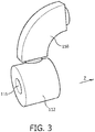
- Fig. 3 schematically depicts an arrangement of a bending magnet 158 and a MR magnet 112.
- the MR magnet 112 is depicted as a single magnet. Nevertheless, the particular design of the MR magnet 112 is as described above
- the PT apparatus 150 comprises guiding means 160, which are provided for controlling the bending magnet 158.
- the control unit 132 is adapted for controlling the guiding means 160.
- the guiding means 160 are adapted for directing the particle beam 154 to the irradiation volume 124. As can be seen in Figs. 1 and 2 , because of the split design of the main magnet 112, the transceiver coil 126 and the gradient coil 128, the particle beam 154 does not intersect the main magnet 112, the transceiver coil 126 and the gradient coil 128.
- the PT apparatus 150 further comprises a rotatable support 162 for supporting the gantry 156.
- the rotatable support 162 surrounds the MRI system 110.
- the rotatable support 162 supports the gantry 156 in an area of an outlet section 164, where the particle beam 154 exits the gantry 156.
- Pulsed electromagnets used to scan the particle beam 154 are preferably located inside a low-field ring 166; this allows the use of efficient scanning magnets with a ferromagnetic return yoke.
- the bending magnet 158 causes inhomogeneities in the magnet field within the main magnet 112, as can be seen by the field distribution sphere 170.
- the PT apparatus 150 further comprises an active compensation coil 200 to provide a homogeneous magnetic field within the MR magnet 112.
- the active compensation coil 200 is arranged to substantially surround at least the imaging volume 122.
- the active compensation coil 200 is further provided in proximity to an outer surface of the main magnet 112. In this position, the active compensation coil 200 is fixed to the outlet section 164 of the gantry 156 and rotatable together with the gantry 156 around the rotational axis R.
- the active compensation coil 200 is driven via driving unit 202.
- the control unit 132 controls the active compensation coil 200 via the driving unit 202. Furthermore, the control unit 132 controls the active compensation coil 200 for canceling a stray field caused by the bending magnet 158 within the imaging volume 122 in the longitudinal direction of the main magnet 112. In this embodiment, the control unit 132 controls the active compensation coil 200 to be energized using the driving unit 202 with a current proportional to a current in the bending magnet 158.
- control unit 132 controls the active compensation coil 200 to actively cancel the z-component of the stray field of the bending magnet 158 across the imaging volume 122 of the MR magnet 112, so that its component along the longitudinal direction of the MR magnet 112 is either homogeneous or zero within the imaging volume 122.
- This control is applied for all rotational positions of the gantry 158 of the particle beam apparatus 150 and for all strengths of the magnetic field of the bending magnet 158.
- the active compensation coil 200 is designed with a suitable shape and current distribution, so that is generates essentially the same magnetic field pattern as the bending magnet 158, but with opposite polarity. Furthermore, the active compensation coil 200 is aligned to the bending magnet 158, so that field patterns of the bending magnet 158 and the active compensation coil 200 match each other. Still further, the active compensation coil 200 has a winding distribution, so that with a control of the current of the active compensation coil 200 the resulting magnetic field, i.e. the magnetic field of the at least one bending magnet together with the magnetic field of the active compensation coil, has a uniform z-component over the entire imaging volume of the MR magnet 112.
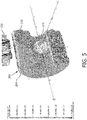
- the active compensation coil 200 comprises a cylindrical support structure, which is not shown in the Figures, and a set of windings 204 arranged at the support structure for carrying a compensation current, as can be seen in Figs 5 - 7 .
- the support structure and the windings 204 are made of non-ferrous materials.
- the windings 204 are formed of copper wire.
- the windings 204 of the active compensation coil 200 are placed on an outer surface of the support structure.
- the windings 204 of the active compensation coil 200 are placed on an inner surface of the support structure.
- the windings 204 are provided on the support structure in accordance with a designed current distribution pattern of the active compensation coil 200 as described below.
- the active compensation coil 200 comprises a metal sheet, whereby electric paths are cut into the metal sheet, and the metal sheet is bent around a cylindrical support structure.
- the support structure and the metal sheet are made of non-ferrous materials.
- the metal sheet is made of copper.
- the metal sheet of the active compensation coil 200 is either placed on an outer or inner surface of the support structure.
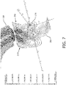
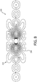
- the active compensation coil 200 comprises two symmetric half coils 210, one of which is shown in Figs. 7 and 8 .
- Fig. 8 only half of the windings 204 of the active compensation coil 200 are depicted compared to Fig. 7 for clarity reasons.
- the active compensation coil 200 is provided with half of the windings 204 compared to the embodiment shown in Fig. 7 .
- the active compensation coil 200 can be driven with the double current compared to the active compensation coil 200 shown in Fig. 7 in order to achieve the same active compensation.
- the active compensation coil 200 is provided with mirror symmetry with respect to a plane including the z-axis of the main magnet 112.
- Each half coil 210 is provided with its windings 204 being separated from the windings 204 of the respective other half coil 210, so that no windings 204 of the active compensation coil 200 cross this symmetry plane.
- the windings 204 of the two half coils 210 are connected in series, even though they appear to be provided in individual windings 204 in the figures. Hence, the same current is applied to the windings 204 shown e.g. in Fig. 8 . A direction of the current is indicated in Fig. 8 by the arrows added to the windings 204.
- the active compensation coil 200 is cooled by air, either through forced or natural convection.
- the windings are provided as hollow conductors for circulation of water as coolant.
- cooling channels are mounted on the surface of the active compensation coil 200 to enable water circulation for cooling.
- the active compensation coil 200 is provided with an opening 206 for passage of the particle beam 154.
- the opening 206 refers to an area of the active compensation coil 200 without conductive elements, i.e. without windings 204.
- a connection window 208 is provided for connection of the split transceiver coil 126 and the transceiver 130.
- a current pattern for the windings 204 of the active compensation coil 200 is be designed by first calculating or measuring a field map of the at least one bending magnet 158 at the location of the imaging volume 122 of the MR magnet 112. These field values are used as field targets for a coil optimization program using a stream function method similar to what is normally used to design MR gradient coils. The cost function in the optimization is the total dissipation in the active compensation coil 200. The resulting current pattern is preferably discretized into the windings 204 each carrying the same operating current.
- the active compensation coil 200 in an alternative embodiment also compensates the fields of other sources of magnetic fields of the particle beam apparatus 150, in particular the active compensation coil 200 compensates the fields of other sources of magnetic fields, which scale with the operating current in the bending magnet 158.
- the active compensation coil 200 also comprises correction windings.
Landscapes
- Health & Medical Sciences (AREA)
- Physics & Mathematics (AREA)
- Engineering & Computer Science (AREA)
- Biomedical Technology (AREA)
- Life Sciences & Earth Sciences (AREA)
- Nuclear Medicine, Radiotherapy & Molecular Imaging (AREA)
- Radiology & Medical Imaging (AREA)
- General Health & Medical Sciences (AREA)
- Public Health (AREA)
- Pathology (AREA)
- Animal Behavior & Ethology (AREA)
- General Physics & Mathematics (AREA)
- Condensed Matter Physics & Semiconductors (AREA)
- Veterinary Medicine (AREA)
- High Energy & Nuclear Physics (AREA)
- Theoretical Computer Science (AREA)
- Pulmonology (AREA)
- Biophysics (AREA)
- Heart & Thoracic Surgery (AREA)
- Medical Informatics (AREA)
- Molecular Biology (AREA)
- Surgery (AREA)
- Radiation-Therapy Devices (AREA)
- Magnetic Resonance Imaging Apparatus (AREA)
Description
- The invention relates to the area of guiding of charged particles to a target zone within a subject of interest, whereby the particles are guided using magnetic resonance imaging.
- In charged particle beam therapy, an energetic charged particle beam is directed at a target zone of a subject. The primary mechanism for interaction of a beam comprising charged particles with matter is through the Coulomb force. The cross section for Coulomb collisions increases as the relative velocity of two particles decreases. As a charged particle beam travels through a subject, it loses energy more and more rapidly. The effect of this is that the majority of the energy of the particle beam is deposited near the end of the beam path. Therefore, a large peak of energy is deposited at the end of the beam path which is called the Bragg peak.
- Accordingly, charged particle beam therapy allows very precise delivery of high dose to a target zone, e.g. to a tumor target, while minimizing the total dose to a subject of interest. However, even small movements of the subject of interest, e.g. of anatomical structures in the path of the beam or a displacement of the target zone, can lead to significant deviations of the delivered dose from the original dose plan. Therefore, it is desirable to use real-time imaging to track the subject of interest and to adapt the beam to the motion of the subject of interest including the motion of organs of the subject of interest. The accuracy of charged particle beam therapy can be significantly improved by real-time guidance based on magnetic resonance (MR) imaging.
- In the field of charged particle beam therapy, different kinds of charged particles can be used for treatment of the subject of interest, e.g. as a cancer treatment. Accordingly, a source of charged particles is required and a beam path to direct the charged particle beam into the subject of interest. One example of charged particle beam therapy is Proton Therapy (PT), where protons are directed into the subject of interest. An example of a combined MR-Proton therapy apparatus is described in
EP 2 379 172 B1 . - For charged particle beam therapy, real-time magnetic resonance imaging (MRI) during the delivery of the charged particle beam is challenging because of the strong magnetic fields associated with MRI and strong magnetic fields used for directing the particle beam to the target zone. Hence, superposition of and interaction between the magnetic fields may cause severe problems, in particular for MRI.
- A static magnetic field is used by Magnetic Resonance Imaging (MRI) scanners to align the nuclear spins of atoms as part of the procedure for producing images within the body of the subject of interest. During an MRI scan, Radio Frequency (RF) pulses generated by a transmitter coil cause perturbations to the local magnetic field, and RF signals emitted by the nuclear spins are detected by a receiver coil. These RF signals are used to construct the MRI images. The transmitter and receiver coils can also be integrated into a single transceiver coil. It is understood that the use of the term transceiver coil also refers to systems where separate transmitter and receiver coils are used.
- Accordingly, the subject of interest is located within a magnetic resonance imaging (MRI) system, and a proton source is provided together with a gantry, which directs the protons into the subject of interest. The gantry is rotatable around a z-axis of the MRI system, i.e. around the z-axis of a main magnet of the MRI system, to direct the radiation towards the subject of interest in a direction substantially perpendicular to the z-axis, which is achieved using at least one bending magnet, also referred to as dipole magnet, in the gantry.
- This setup brings the at least one bending magnet of the proton therapy system in close proximity to the main magnet of the MRI system. The bending magnet generates a strong dipole field, which can have a field strength of e.g. ∼1.5T, in a large aperture and potentially creates a strong stray-field in the direction perpendicular to the bending plane. Since this stray field drops off rapidly with distance from the dipole magnet, it also has components in other directions, notably along the direction of the MRI magnet's main field, i.e. in the direction of the z-axis. This field will cause image distortion and other artifacts. A static compensation of the PT field at the MRI system, e.g. using shimming, is not feasible because of the rotation of the bending magnets about the z-axis of the MRI system. Furthermore, the strength of the field of the dipole magnet has to be modulated along with modulation of the energy of the charged particles. The energy of the charged particles is adapted to move the Bragg zone along the beam direction, e.g. charged particles with increased energy enter further into the subject of interest than charged particles with lower energy. Depending on the energy of the charged particles, also the strength of the external field of the bending magnet will thus also be variable.
- In this context, a method is known from document
WO 2012/164527 A1 A for correcting a magnetic field of an MRI radiotherapy apparatus comprising a magnetic resonance imaging system and a radiation therapy system. The MRI system includes a magnet for generating the magnetic field within an imaging zone. The magnet generates a magnetic field with a zero crossing outside of the imaging zone. The medical apparatus further comprises a gantry configured for rotating a ferromagnetic component about a rotational axis. The method comprises the step of installing a magnetic correcting element located on a radial path perpendicular to the rotational axis. The magnetic correcting element is positioned on the radial path such that change in the magnetic field within the imaging zone due to the ferromagnetic component is reduced. The method further comprises repeatedly: measuring the magnetic field within the imaging zone; determining the change in the magnetic field in the imaging zone; and adjusting the position of the magnetic correcting element along the radial path if the change in the magnetic field is above a predetermined threshold. - Furthermore, post-published
WO 2014/121991 A1 refers to a medical apparatus comprising a magnetic resonance imaging system; magnetic compensation coils for compensating for magnetic inhomogeneities within the imaging zone; a gantry operable for rotating about the imaging zone; a position sensor for measuring the angular position and the angular velocity of the gantry; at least one magnetic field distorting component in the gantry, a memory storing machine executable instructions and field correction data. The instructions cause a processor to: receive the position and angular velocity data from the position sensor; determine coil control commands for controlling the magnetic compensation coils using the field correction data, the position data and the angular velocity data; control the magnetic compensation coils to compensate for magnetic inhomogeneities within the imaging zone using the coil control commands; and acquire the magnetic resonance data. - It is an object of the invention to enable reliable magnetic resonance imaging when performing magnetic resonance imaging. It is a further aspect of the invention to improve particle beam treatments for providing a particle beam of charged particles to a subject of interest by improved guidance using improved magnetic resonance imaging. It is a particular object of the present invention to provide a medical apparatus comprising a magnetic resonance imaging system for acquiring magnetic resonance data from an imaging volume of a subject of interest and a particle beam line for providing a particle beam of charged particles. There is also described a shielding method, not being part of the invention, which enable reliable compensation of a magnetic field of bending magnets for directing the particle beam to an irradiation volume within the imaging volume during operation of the particle beam apparatus within the imaging volume.
- This object is achieved by a medical apparatus comprising a magnetic resonance imaging system for acquiring magnetic resonance data from an imaging volume covering at least partially a subject of interest, wherein the magnetic resonance imaging system comprises a main magnet for generating a magnetic field within the imaging volume, a particle beam apparatus having a particle beam line for providing a particle beam of charged particles, including a gantry configured for rotating around a rotational axis, which is arranged in the longitudinal direction of the main magnet, wherein the gantry comprises at least one bending magnet for directing the particle beam to an irradiation volume within the imaging volume, an active compensation coil, which is arranged to substantially surround at least the imaging volume and which is provided in proximity to an outer surface of the main magnet, and a control unit for controlling the active compensation coil for canceling a stray field caused by the at least one bending magnet within the imaging volume at least in the longitudinal direction of the main magnet.
- A shielding method for use in a medical apparatus, comprises the steps of providing a magnetic resonance imaging system for acquiring magnetic resonance data from an imaging volume covering at least partially a subject of interest, wherein the magnetic resonance imaging system comprises a main magnet for generating a magnetic field within the imaging volume, providing a particle beam apparatus having a particle beam line for a particle beam of charged particles, including a gantry configured for rotating around a rotational axis, which is arranged in the longitudinal direction of the main magnet, wherein the gantry comprises at least one bending magnet for directing the particle beam to an irradiation volume within the imaging volume, providing an active compensation coil, which is arranged to substantially surround at least the imaging volume and which is provided in proximity to an outer surface of the main magnet, and controlling the active compensation coil for canceling a stray field caused by the at least one bending magnet within the imaging volume at least in the longitudinal direction of the main magnet.
- Accordingly, the active compensation coil actively cancels the z-component of the stray field of the at least one bending magnet across the field of view or imaging volume of the MR magnet. Hence, the stray field of the at least one bending magnet of the particle beam apparatus is actively compensated in such a way that its component along a main field direction of the MR magnet, i.e. a longitudinal direction or z-axis of the MR magnet, is either homogeneous or zero over the imaging volume of the MR system. This is preferably applied for all rotational positions of the gantry of the particle beam apparatus and for all strengths of the magnetic field of the at least one bending magnet. Thus the disturbing effect of the particle beam apparatus, in particular of the at least one bending magnet of the particle beam apparatus, on the quality of the MR imaging is reduced or eliminated. The bending magnet is also referred to as dipole magnet.
- Shielding of the at least one bending magnet itself, i.e. shielding the magnetic field at the source is not easy due to the great strength of this magnetic field. Passively shielding with ferromagnetic material would be problematic, because this shielding material would also be exposed to the stray field of the MRI magnet and thereby create additional field inhomogeneity across the imaging volume. Moreover, the strength of the magnetic field of the at least one bending magnet and hence also its stray field is not constant in time, but varies with the energy of the charged particles. As most treatment procedures involve a modulation of the energy of the charged particles in order to move the Bragg peak in beam direction, a static compensation is not suitable to cancel the effect of the magnetic field of the at least one bending magnet. These disadvantages can be overcome by the proposed active shielding using the active compensation coil.
- Active compensation of the magnetic field of the at least one bending magnet is most efficient when the active compensation coil is as close as possible to the volume where the compensating field is required. Consequently, it is preferred to provide the active compensation coil as far away as possible from the at least one bending magnet. Therefore, it is preferred that the active compensation coil has its windings distributed over a cylindrical surface located just outside the cylindrical outer surface of the magnet, or outside the cylindrical outer surface of a cryostat of the main magnet. Preferably, the magnet of the MRI does not have any protrusions, so that the active compensation coil can be located in close proximity to the main magnet and as far away from the at least one bending magnet as possible. In some state of the art magnets, such protrusions are provided e.g. for cryogenic or vacuum ports, magnet support attachments, magnet feet, or other components.
- Preferably, the gantry is provided to direct the beam of charged particles to the subject of interest with an angle perpendicular to the z-axis of the main magnet. Accordingly, the passage of the charged particles through the subject of interest can be limited to a minimum, thereby reducing a dose for the subject of interest.
- The magnetic field of at least one of the bending magnets, i.e. the bending magnet closest to an outlet section of the gantry, is directed perpendicular to the z-axis of the magnet and rapidly drops off with distance from an outlet section of the gantry. Due to this field gradient, the field of the at least one bending magnet at the imaging volume of the MR magnet also has a z-component, which is zero in the z=0 plane and increases in magnitude away from this midplane of the MR magnet. For a tentative design of such a dipole magnet, the field gradient across the imaging volume is of the order of 100 ppm. For the proper operation of the MRI system it is most important and generally sufficient to eliminate this z-component of the field of the at least one bending magnet.
- Preferably, the active compensation coil is provided with a suitable shape and current distribution, so that is generates essentially the same magnetic field pattern as the at least one bending magnet, but with opposite polarity. This is achieved by a respective design of the active compensation coil.
- Preferably, the active compensation coil has a winding distribution, so that with a control of the current of the active compensating coil the resulting magnetic field, i.e. the magnetic field of the at least one bending magnet together with the magnetic field of the active compensation coil, has a uniform z-component over the entire field of view of the MR magnet, i.e. the imaging volume. The transverse components of the total field of the at least one bending magnet and the active compensation coil need not be zero. As long as the total transverse field is small enough that the vector sum of the transverse field and the main MRI magnet field is not significantly different from the magnetic field of the MR magnet, the imaging process of the MRI system will not be affected by the transverse field.
- A preferred choice for the strength of the resulting z-component of the magnetic field of the at least one bending magnet of the particle beam apparatus and the active compensation coil is zero. Even with this design restriction, a high number of solutions for the current distribution in the active compensating coil can be obtained, i.e. the design of the active compensation coils is essentially not limited by this specification. The special case that also the transverse components of the net field of the at least one bending magnet and the compensation coil be zero is attractive because it would eliminate other possible interactions between the magnetic resonance imaging system and the particle beam apparatus. Nevertheless, this implementation requires a powerful design of the active compensation coil, which would result in a complex design compared to an active compensation coil for cancelling essentially the overall z-component of the magnetic field.
- Preferably, a current pattern for the active compensation coil is be designed by first calculating or measuring a field map of the at least one bending magnet at the location of the imaging volume of the MR magnet. These field values can then be used as field targets for a coil optimization program using the stream function method. This is similar to what is normally used to design MR gradient coils. The cost function in the optimization can then be the total dissipation in the active compensation coil. The resulting current pattern is preferably discretized into windings each carrying the same operating current.
- Further preferred, the active compensation coil also compensates the fields of other sources of magnetic fields of the particle beam apparatus. Preferably, the active compensation coil also compensates the fields of other sources of magnetic fields, which scale with the operating current in the at least one bending magnet.
- Preferably, the a particle beam apparatus is a Proton Therapy (PT) apparatus for directing a beam of protons to the subject of interest. PT apparatus are known in the Art and do not have to be discussed in detail.
- According to a preferred embodiment the active compensation coil is fixed to the gantry and rotatable together with the gantry around the rotational axis. With the active compensation coil fixed to the gantry, the active compensation coil can easily rotate with the gantry and the at least one bending magnet, so that magnetic fields generated by the at least one bending magnet and magnetic files for compensation thereof, which are generated by the active compensation coil, rotate together . This facilitates compensation of the rotating magnetic fields.
- According to an alternative embodiment, the active compensation coil is rotatable around the rotational axis of the gantry, but the rotation of the active compensation coil is controlled independently from the rotation of the gantry. Accordingly, the active compensation coil can be easily added to existing medical apparatus. It can also be added easily existing particle beam apparatus. The design of the existing apparatus does not have to be changed.
- According to a preferred embodiment the active compensation coil is fixed to an outlet section of the gantry. The outlet section of the gantry refers to the part of the gantry, where the particle beam leaves the gantry to enter the subject of interest. Active compensation of the magnetic field of the at least one bending magnet is most efficient when the active compensation coil is as close as possible to the volume where the compensating field is required. Consequently, it is preferred to provide the active compensation coil as far away as possible from the at least one bending magnet, i.e. the active compensation coil is fixed to the outlet section, which is close to the main magnet.
- According to a preferred embodiment the active compensation coil comprises a cylindrical support structure and a set of windings arranged at the support structure for carrying a compensation current. The support structure and the windings are preferably made of non-ferrous materials to avoid influences on the magnetic field inside the main magnet, in particular in the imaging volume. Preferably, the windings are made of copper. The windings of the active compensation coil can be placed on an outer or inner surface of the support structure. The windings are preferably provided on the support structure in accordance with a designed current distribution pattern of the active compensation coil as discussed above.
- According to a preferred embodiment the active compensation coil comprises a metal sheet, whereby electric paths are cut into the metal sheet, and the metal sheet is bent around a cylindrical support structure. The support structure and the metal sheet are preferably made of non-ferrous materials to avoid influences on the magnetic field inside the main magnet, in particular in the imaging volume. Preferably, the metal sheet is made of copper. The metal sheet of the active compensation coil can be placed on an outer or inner surface of the support structure. The electric paths are preferably provided in the metal sheet in accordance with a designed current distribution pattern of the active compensation coil as discussed above.
- According to a preferred embodiment the active compensation coil is provided with at least one opening for passage of the particle beam. The at least one opening refers to an area of the active compensation coil without conductive elements. Hence, the at least one opening serves as a window for the beam of charged particles to reach the subject of interest. Multiple openings can be provided e.g. in the case of a non-rotating active coil, so that the beam of charged particles can be directed to the subject of interest from multiple directions through the multiple openings.
- Preferably, the active compensation coil has mirror symmetry with respect to a plane including the z-axis of the main magnet. Further preferred, no conductors of the active compensation coil cross this symmetry plane. Accordingly, a mechanical split in the cylindrical structure of the active compensation coil and its support structure can be provided to allow the active compensation coil to be installed around the MRI magnet in two halves, which are joined together by bolts or other means after placing the coil around the MRI main magnet. The windings of the two halves of the active compensation coil are preferably connected in series.
- According to a preferred embodiment the active compensation coil is cooled by air, through forced or natural convection, or by water flowing through cooling channels mounted on the surface of the active compensation coil or through the windings of the active compensation coil itself if these are made from a hollow conductor. Since the active compensation coil preferably rotates with the bending dipole, it is possible to use a water-cooling system of the dipole magnet to also cool the active compensation coil.
- According to a preferred embodiment the control unit is adapted to control the active compensation coil to be energized with a current proportional to a current in the at least one bending magnet. Hence, the compensation of the magnetic fields of the at least one bending magnet can be facilitated, since variation in the field strength of the at least one bending magnet, which impact on the strength of the stray field, are directly applied to the active compensation coil as well. With a proper design of the active compensation coil as discussed above, compensation of the stray fields can be automatically performed by driving the active compensation coil with the proportional current.
- According to a preferred embodiment the at least one bending magnet and the active compensation coil are provided having the same operating current for matching fields, and the active compensation coil and the at least one bending magnet are electrically connected in series to be driven by the same operating current. Hence, the compensation of the magnetic fields of the at least one bending magnet can be further facilitated, since variations in the field strength of the at least one bending magnet, which impact on the strength of the stray field, are directly compensated by the active compensation coil. With a proper design of the active compensation coil as discussed above, compensation of the stray fields can be automatically performed.
- According to a preferred embodiment the medical apparatus comprises a driving device for powering the active compensation coil, and the control unit is adapted to control the driving device using magnet set-point information from the particle beam apparatus. Hence, the active compensation coil can be driven independently from the current through the at least one bending magnet, i.e. the active compensation coil is driven in an independent mode. In this independent mode of operation it is useful to generate and use a look-up table of proper values of compensation currents in dependence of a current in the bending magnet. The look-up table can be generated by magnetic simulation or by measurement of the fields of dipole magnet and the active compensation coil. If magnetic hysteresis in ferromagnetic parts of the dipole magnet affects the external field in dependence of current, it is advantageous to provide separate look-up tables for the cases that the dipole current is increased or decreased.
- According to a preferred embodiment the active compensation coil comprises a multilayer coils setup with at least two coaxial coil layers. The multilayer setup can be achieved e.g. by providing a cylindrical support structure, where a set of windings is provided on its inner cylindrical surface and another set of windings is provided on its outer cylindrical surface, thereby forming two coil layers in this embodiment. Preferably, the coil layers can be driven independently. Additional coil layers can be added to an active compensation coil to compensate for magnetic fields generated by any additional source of magnetic fields, e.g. when multiple bending and/or scanning magnets are used. The multilayer coil setup enables compensation of non-linearities in the external field of the dipole magnet, which might be caused by saturation in the iron return yoke of the bending magnet. Furthermore, in case the particle beam apparatus comprises multiple magnets, which are driven with currents with different time dependency, the multilayer setup is preferably used to compensate for the magnetic fields generated by these sources of magnetic stray fields.
- Alternatively, the active compensation coil may be provided as an active compensation coil assembly comprising at least two independent coils. The principles discussed above in respect to the multilayer coil setup also apply to the active compensation coil assembly comprising at least two independent coils.
- According to a preferred embodiment the active compensation coil comprises at least one correction winding. Typically, the at least one correction winding is small compared to the size of the active compensation coil. The at least one correction winding enables a fine-adjustment of the compensating effect which might be desired to compensate field errors due to manufacturing or alignment accuracy.
- According to a preferred embodiment the method comprises aligning the active compensation coil to the at least one bending magnet. In particular, when the active compensation coil is attached to the gantry, which rotates around the centerline of the MR magnet, the compensation coil needs to be accurately aligned to the at least one bending magnet. With the alignment of the at least one bending magnet and the active compensation coil, the field patterns of the at least one bending magnet and the active compensation coil can match each other, which facilitates the compensation of the magnetic field of the at least one bending magnet.
- The principles discussed above in respect to the medical apparatus apply also, when the active compensation coil is used together with the particle beam apparatus alone, i.e. without the MRI system. Hence, a cylindrical space can be provided inside the active compensation coil, where magnetic stray fields can be reliably compensated, at least in the direction of the rotational axis of the gantry.
- These and other aspects of the invention will be apparent from and elucidated with reference to the embodiments described hereinafter. Such an embodiment does not necessarily represent the full scope of the invention, however, and reference is made therefore to the claims and herein for interpreting the scope of the invention.
- In the drawings:
-
Fig. 1 shows a generalized cross-sectional view of an embodiment of a medical apparatus according to a first embodiment with an active compensation coil, -
Fig. 2 shows the medical apparatus according to the first embodiment ofFig. 1 in a perspective view, whereby the active compensation coil is omitted, -
Fig. 3 shows a schematic arrangement of a bending magnet and a MR magnet in accordance withFig. 2 in a perspective view, -
Fig. 4 shows a magnetic field distribution in the MR magnet of a MR system of the medical apparatus ofFig. 1 without active shielding as known from the prior Art in a perspective, cross-sectional view, -
Fig. 5 shows a magnetic field distribution in the MR magnet of a MR system of the medical apparatus ofFig. 1 with an active compensation coil in a perspective, cross-sectional view, -
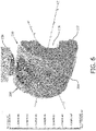
Fig. 6 shows windings of one half of an active compensation coil in a perspective, cross-sectional view together with the MR magnet of the MR system of the medical apparatus in accordance withFig. 5 , with the cut-plane of the drawing located at a symmetry plane of the compensation coil, -
Fig. 7 shows the windings of one half of the active compensation coil as shown inFigs. 5 and6 in a perspective, cross-sectional view without the MR magnet, with the cut-plane of the drawing located at the symmetry plane of the compensation coil, and -
Fig. 8 shows a planar view the windings of one half of the active compensation coil of an active compensation coil in accordance withFig. 7 , where half of the windings has been omitted for clarity reasons. -
Figs. 1 and2 show amedical apparatus 100 according to a preferred embodiment. - The
medical apparatus 100 comprises a magnetic resonance imaging (MRI)system 110 that comprises a magnetic resonance (MR)magnet 112, also referred to as main magnet, which is provided as split magnet with twosubmagnets 114. As can be seen in detail inFig. 2 , each sub-magnet 114 comprises acryogenic chamber 136, which is provided with aradiation shield 138. Within thecryogenic chamber 136 are arranged innersuperconducting coils 140 adapted for generating the main magnetic field and an outersuperconducting shielding coil 142. Thesuperconducting shielding coil 142 is adapted such that there is a region of zero magnetic field surrounding the sub-magnet 114. - Within a
bore 116 of the sub-magnets 114, there is provided asupport 118 adapted for receiving a subject ofinterest 120. Between the twosub-magnets 114, there is animaging volume 122 where the magnetic field is uniform enough that magnetic resonance imaging data can be acquired. Within theimaging volume 122 there is airradiation zone 124, also referred to astarget zone 124, which is discussed later in detail. Magnetic resonance imaging data is acquired using asplit transceiver coil 126 in this embodiment. Spatial encoding of the information is performed by means of asplit gradient coil 128. In this embodiment, thegradient coil 128 is located within thebore 116 of themain magnet 112. - In this embodiment, the
split transceiver coil 126 is set directly on the subject ofinterest 120. In other embodiments the coils used for acquiring magnetic resonance imaging data can be mounted within thebore 116 of theMR magnet 112, they can be mounted on supports, or they can be mounted to thegradient coil 128. - The
transceiver coil 126 is connected to atransceiver 130. Thetransceiver 130 is able to emit and also receive radio frequency signals. Thetransceiver 130 interfaces with acontrol unit 132. Thesplit gradient coil 128 is powered by agradient amplifier 134, which is controlled by thecontrol unit 132. Thegradient amplifier 134 is a power amplifier capable of supplying the gradient coils 128 with current. Thecontrol unit 132 is a data processing device which is adapted for constructing images from magnetic resonance data obtained by thetransceiver 126. - The
medical apparatus 100 further comprises aparticle beam apparatus 150, which is a Proton Therapy (PT) apparatus in this embodiment. ThePT apparatus 150 has aparticle beam line 152 for aparticle beam 154 of charged particles, including agantry 156 configured for rotating around a rotational axis R, which is arranged in the longitudinal direction of themain magnet 112. The gantry comprises onebending magnet 158 for directing theparticle beam 154 to theirradiation volume 124 within theimaging volume 122. In this embodiment, theparticle beam 154 is directed to the subject ofinterest 120 with an angle perpendicular to the z-axis of themain magnet 112. Additional bending magnets, which are provided in thegantry 156, are not visible and are also not discussed in detail.Fig. 3 schematically depicts an arrangement of abending magnet 158 and aMR magnet 112. TheMR magnet 112 is depicted as a single magnet. Nevertheless, the particular design of theMR magnet 112 is as described above. - The
PT apparatus 150 comprises guiding means 160, which are provided for controlling thebending magnet 158. Thecontrol unit 132 is adapted for controlling the guiding means 160. The guiding means 160 are adapted for directing theparticle beam 154 to theirradiation volume 124. As can be seen inFigs. 1 and2 , because of the split design of themain magnet 112, thetransceiver coil 126 and thegradient coil 128, theparticle beam 154 does not intersect themain magnet 112, thetransceiver coil 126 and thegradient coil 128. - The
PT apparatus 150 further comprises arotatable support 162 for supporting thegantry 156. As can be seen inFig. 2 , therotatable support 162 surrounds theMRI system 110. Therotatable support 162 supports thegantry 156 in an area of anoutlet section 164, where theparticle beam 154 exits thegantry 156. - Pulsed electromagnets used to scan the
particle beam 154 are preferably located inside a low-field ring 166; this allows the use of efficient scanning magnets with a ferromagnetic return yoke. - As can be seen in
Fig. 4 , when operating theMRI system 110 and thePT apparatus 150 together, thebending magnet 158 causes inhomogeneities in the magnet field within themain magnet 112, as can be seen by thefield distribution sphere 170. - The
PT apparatus 150 further comprises anactive compensation coil 200 to provide a homogeneous magnetic field within theMR magnet 112. Theactive compensation coil 200 is arranged to substantially surround at least theimaging volume 122. Theactive compensation coil 200 is further provided in proximity to an outer surface of themain magnet 112. In this position, theactive compensation coil 200 is fixed to theoutlet section 164 of thegantry 156 and rotatable together with thegantry 156 around the rotational axis R. - The
active compensation coil 200 is driven via drivingunit 202. Thecontrol unit 132 controls theactive compensation coil 200 via thedriving unit 202. Furthermore, thecontrol unit 132 controls theactive compensation coil 200 for canceling a stray field caused by the bendingmagnet 158 within theimaging volume 122 in the longitudinal direction of themain magnet 112. In this embodiment, thecontrol unit 132 controls theactive compensation coil 200 to be energized using thedriving unit 202 with a current proportional to a current in thebending magnet 158. - Hence, the
control unit 132 controls theactive compensation coil 200 to actively cancel the z-component of the stray field of thebending magnet 158 across theimaging volume 122 of theMR magnet 112, so that its component along the longitudinal direction of theMR magnet 112 is either homogeneous or zero within theimaging volume 122. This control is applied for all rotational positions of thegantry 158 of theparticle beam apparatus 150 and for all strengths of the magnetic field of thebending magnet 158. - In this embodiment the
active compensation coil 200 is designed with a suitable shape and current distribution, so that is generates essentially the same magnetic field pattern as thebending magnet 158, but with opposite polarity. Furthermore, theactive compensation coil 200 is aligned to thebending magnet 158, so that field patterns of thebending magnet 158 and theactive compensation coil 200 match each other. Still further, theactive compensation coil 200 has a winding distribution, so that with a control of the current of theactive compensation coil 200 the resulting magnetic field, i.e. the magnetic field of the at least one bending magnet together with the magnetic field of the active compensation coil, has a uniform z-component over the entire imaging volume of theMR magnet 112. - The
active compensation coil 200 comprises a cylindrical support structure, which is not shown in the Figures, and a set ofwindings 204 arranged at the support structure for carrying a compensation current, as can be seen inFigs 5 - 7 . The support structure and thewindings 204 are made of non-ferrous materials. Thewindings 204 are formed of copper wire. In this embodiment, thewindings 204 of theactive compensation coil 200 are placed on an outer surface of the support structure. In an alternative embodiment, thewindings 204 of theactive compensation coil 200 are placed on an inner surface of the support structure. Thewindings 204 are provided on the support structure in accordance with a designed current distribution pattern of theactive compensation coil 200 as described below. - In an alternative embodiment, the
active compensation coil 200 comprises a metal sheet, whereby electric paths are cut into the metal sheet, and the metal sheet is bent around a cylindrical support structure. The support structure and the metal sheet are made of non-ferrous materials. The metal sheet is made of copper. The metal sheet of theactive compensation coil 200 is either placed on an outer or inner surface of the support structure. - As can be best seen in
Figs. 7 and8 , theactive compensation coil 200 comprises two symmetric half coils 210, one of which is shown inFigs. 7 and8 . InFig. 8 , only half of thewindings 204 of theactive compensation coil 200 are depicted compared toFig. 7 for clarity reasons. Nevertheless, in an alternative embodiment, theactive compensation coil 200 is provided with half of thewindings 204 compared to the embodiment shown inFig. 7 . In this case, theactive compensation coil 200 can be driven with the double current compared to theactive compensation coil 200 shown inFig. 7 in order to achieve the same active compensation. - With the two
half coils 210, theactive compensation coil 200 is provided with mirror symmetry with respect to a plane including the z-axis of themain magnet 112. Eachhalf coil 210 is provided with itswindings 204 being separated from thewindings 204 of the respectiveother half coil 210, so that nowindings 204 of theactive compensation coil 200 cross this symmetry plane. Thewindings 204 of the twohalf coils 210 are connected in series, even though they appear to be provided inindividual windings 204 in the figures. Hence, the same current is applied to thewindings 204 shown e.g. inFig. 8 . A direction of the current is indicated inFig. 8 by the arrows added to thewindings 204. - In this embodiment the
active compensation coil 200 is cooled by air, either through forced or natural convection. In an alternative embodiment, the windings are provided as hollow conductors for circulation of water as coolant. In a still further embodiment, cooling channels are mounted on the surface of theactive compensation coil 200 to enable water circulation for cooling. - As can be seen in
Fig. 1 , theactive compensation coil 200 is provided with anopening 206 for passage of theparticle beam 154. Theopening 206 refers to an area of theactive compensation coil 200 without conductive elements, i.e. withoutwindings 204. As can be seen inFig. 1 , aconnection window 208 is provided for connection of thesplit transceiver coil 126 and thetransceiver 130. - A current pattern for the
windings 204 of theactive compensation coil 200 is be designed by first calculating or measuring a field map of the at least onebending magnet 158 at the location of theimaging volume 122 of theMR magnet 112. These field values are used as field targets for a coil optimization program using a stream function method similar to what is normally used to design MR gradient coils. The cost function in the optimization is the total dissipation in theactive compensation coil 200. The resulting current pattern is preferably discretized into thewindings 204 each carrying the same operating current. Theactive compensation coil 200 in an alternative embodiment also compensates the fields of other sources of magnetic fields of theparticle beam apparatus 150, in particular theactive compensation coil 200 compensates the fields of other sources of magnetic fields, which scale with the operating current in thebending magnet 158. Theactive compensation coil 200 also comprises correction windings. - While the invention has been illustrated and described in detail in the drawings and foregoing description, such illustration and description are to be considered illustrative or exemplary and not restrictive; the invention is not limited to the disclosed embodiments. Other variations to the disclosed embodiments can be understood and effected by those skilled in the art in practicing the claimed invention, from a study of the drawings, the disclosure, and the appended claims. In the claims, the word "comprising" does not exclude other elements or steps, and the indefinite article "a" or "an" does not exclude a plurality. The mere fact that certain measures are recited in mutually different dependent claims does not indicate that a combination of these measures cannot be used to advantage. Any reference signs in the claims should not be construed as limiting the scope.
-
- 100
- medical apparatus
- 110
- magnetic resonance imaging (MRI) system
- 112
- magnetic resonance (MR) magnet, main magnet
- 114
- submagnet
- 116
- bore
- 118
- support
- 120
- subject of interest
- 122
- imaging volume
- 124
- irradiation volume, target zone
- 126
- split transceiver coil
- 128
- split gradient coil
- 130
- transceiver
- 132
- control unit
- 134
- gradient amplifier
- 136
- cryogenic chamber
- 138
- radiation shield
- 140
- inner superconducting coil
- 142
- outer superconducting coil
- 150
- particle beam apparatus, proton therapy apparatus
- 152
- particle beam line
- 154
- particle beam
- 156
- gantry
- 158
- bending magnet
- 160
- guiding means
- 162
- rotatable support
- 164
- outlet section
- 166
- low-field ring
- 170
- field distribution sphere
- 200
- active compensation coil
- 202
- driving unit
- 204
- winding
- 206
- opening
- 208
- connection window
- 210
- half coil
Claims (11)
- A medical apparatus (100) comprising
a magnetic resonance imaging system (110) for acquiring magnetic resonance data from an imaging volume (122) covering at least partially a subject of interest (120), wherein the magnetic resonance imaging system (110) comprises a main magnet (112) for generating a magnetic field within the imaging volume (122),
a particle beam apparatus (150) having a particle beam line (152) for a particle beam (154) of charged particles, including a gantry (156) configured for rotating around a rotational axis (R), which is arranged in the longitudinal direction of the main magnet (112), wherein the gantry (156) comprises at least one bending magnet (158) for directing the particle beam (154) to an irradiation volume (124) within the imaging volume (122),
an active compensation coil (200), which is arranged to substantially surround at least the imaging volume (122) and which is provided in proximity to an outer surface of the main magnet (112) and outside the outer surface of the main magnet, and a control unit (132) for controlling the active compensation coil (200) for canceling a stray field caused by the at least one bending magnet (158) within the imaging volume (122) at least in the longitudinal direction of the main magnet (112). - The medical apparatus (100) according to claim 1, whereby
the active compensation coil (200) is fixed to the gantry (156) and rotatable together with the gantry (156) around the rotational axis (R). - The medical apparatus (100) according to claim 2, whereby
the active compensation coil (200) is fixed to an outlet section (164) of the gantry (156). - The medical apparatus (100) according to any of preceding claims 1 to 3, whereby
the active compensation coil (200) comprises a cylindrical support structure and a set of windings (204) arranged at the support structure for carrying a compensation current. - The medical apparatus (100) according to any of preceding claims 1 to 4, whereby
the active compensation coil (200) comprises a metal sheet, whereby electric paths are cut into the metal sheet, and the metal sheet is bent around a cylindrical support structure. - The medical apparatus (100) according to any of preceding claims 1 to 5, whereby
the active compensation coil (200) is provided with at least one opening (206) for passage of the particle beam (154). - The medical apparatus (100) according to any of preceding claims 1 to 6, whereby
the control unit (132) is adapted to control the active compensation coil (200) to be energized with a current proportional to a current in the at least one bending magnet (158). - The medical apparatus (100) according to any of preceding claims 1 to 7, whereby
the at least one bending magnet (158) and the active compensation coil (200) are provided having the same operating current for matching fields, and
the active compensation coil (200) and the at least one bending magnet (158) are electrically connected in series to be driven by the same operating current. - The medical apparatus (100) according to any of preceding claims 1 to 7, whereby
the medical apparatus (100) comprises a driving device (202) for powering the active compensation coil (200), and
the control unit (132) is adapted to control the driving device (202) using magnet set-point information from the particle beam apparatus (150). - The medical apparatus (100) according to any of preceding claims 1 to 9 whereby
the active compensation coil (200) comprises a multilayer coils setup with at least two coaxial coil layers. - The medical apparatus (100) according to any of preceding claims 1 to 10, whereby
the active compensation coil (200) comprises at least one correction winding.
Applications Claiming Priority (2)
| Application Number | Priority Date | Filing Date | Title |
|---|---|---|---|
| EP14174681 | 2014-06-27 | ||
| PCT/EP2015/063783 WO2015197475A1 (en) | 2014-06-27 | 2015-06-19 | Charged particle beam therapy and magnetic resonance imaging |
Publications (2)
| Publication Number | Publication Date |
|---|---|
| EP3160585A1 EP3160585A1 (en) | 2017-05-03 |
| EP3160585B1 true EP3160585B1 (en) | 2019-02-27 |
Family
ID=50982835
Family Applications (1)
| Application Number | Title | Priority Date | Filing Date |
|---|---|---|---|
| EP15729854.8A Not-in-force EP3160585B1 (en) | 2014-06-27 | 2015-06-19 | Charged particle beam therapy and magnetic resonance imaging |
Country Status (6)
| Country | Link |
|---|---|
| US (1) | US10850127B2 (en) |
| EP (1) | EP3160585B1 (en) |
| JP (1) | JP6449920B2 (en) |
| CN (1) | CN106456994B (en) |
| RU (1) | RU2681075C2 (en) |
| WO (1) | WO2015197475A1 (en) |
Families Citing this family (22)
| Publication number | Priority date | Publication date | Assignee | Title |
|---|---|---|---|---|
| CA3090069C (en) * | 2009-07-15 | 2024-05-07 | Viewray Technologies, Inc. | Method and apparatus for shielding a linear accelerator and a magnetic resonance imaging device from each other |
| JP6382208B2 (en) | 2012-10-26 | 2018-08-29 | ビューレイ・テクノロジーズ・インコーポレイテッドViewRay Technologies, Inc. | System and computer program product |
| US9446263B2 (en) | 2013-03-15 | 2016-09-20 | Viewray Technologies, Inc. | Systems and methods for linear accelerator radiotherapy with magnetic resonance imaging |
| US10894174B2 (en) * | 2015-12-02 | 2021-01-19 | Koninklijke Philips N.V. | Rotatable magnet for proton therapy |
| CN109310879A (en) | 2016-03-02 | 2019-02-05 | 优瑞技术公司 | Utilize the Part Ther of magnetic resonance imaging |
| EP3305368A1 (en) | 2016-10-07 | 2018-04-11 | Ion Beam Applications | Particle therapy apparatus comprising an mri |
| EP3306336A1 (en) | 2016-10-07 | 2018-04-11 | Ion Beam Applications S.A. | Hadron therapy device and mri device having magnetic field correcting means |
| EP3306335A1 (en) * | 2016-10-07 | 2018-04-11 | Ion Beam Applications S.A. | Apparatus and method for localizing the bragg peak of a hadron beam traversing a target tissue by magnetic resonance imaging |
| EP3308834B1 (en) | 2016-10-11 | 2019-01-09 | Ion Beam Applications | Particle therapy apparatus comprising an mri |
| CN106856654B (en) * | 2017-03-13 | 2019-08-02 | 深圳市金石医疗科技有限公司 | Self-shielding type magnetic resonance device |
| GB2567193A (en) * | 2017-10-05 | 2019-04-10 | Elekta ltd | Image guided radiation therapy apparatus |
| WO2019112880A1 (en) | 2017-12-06 | 2019-06-13 | Viewray Technologies, Inc. | Optimization of multimodal radiotherapy |
| US20210299462A1 (en) * | 2018-06-18 | 2021-09-30 | National Institutes For Quantum And Radiological Science And Technology | Particle beam irradiation system, particle beam irradiation method, irradiatiion planning program, irradiation planning device, electromagnetic field generator, and irradiation device |
| GB2576579A (en) * | 2018-08-24 | 2020-02-26 | Magnetic Shields Ltd | Magnetic shield device |
| EP3639892B1 (en) * | 2018-10-15 | 2021-08-04 | Elekta Limited | Radiotherapy system and operating method |
| CN114668987A (en) | 2018-11-14 | 2022-06-28 | 上海联影医疗科技股份有限公司 | Radiation therapy system |
| CN109847196B (en) * | 2018-12-29 | 2024-07-19 | 佛山瑞加图医疗科技有限公司 | Magnetic field compensation system and method for a magnetic resonance guided radiotherapy system |
| GB2582009B (en) * | 2019-03-08 | 2021-04-07 | Siemens Healthcare Ltd | Split magnet with rotating central component |
| US20210038922A1 (en) * | 2019-08-05 | 2021-02-11 | The Board Of Regents Of The University Of Texas System | Inhomogeneous MRI System |
| CN111580030B (en) * | 2020-05-13 | 2022-04-22 | 山东省肿瘤防治研究院(山东省肿瘤医院) | Magnetic field preparation structure, equipment and system for fusion of nuclear magnetic resonance and radiotherapy |
| CN115916332A (en) * | 2020-06-17 | 2023-04-04 | 上海联影医疗科技股份有限公司 | System and method for magnetic resonance imaging |
| EP4152030B1 (en) * | 2021-09-17 | 2024-07-03 | Siemens Healthineers AG | Gradient coil assembly for a magnetic resonance imaging device and magnetic resonance imaging device |
Family Cites Families (24)
| Publication number | Priority date | Publication date | Assignee | Title |
|---|---|---|---|---|
| US6198957B1 (en) | 1997-12-19 | 2001-03-06 | Varian, Inc. | Radiotherapy machine including magnetic resonance imaging system |
| DE19928110A1 (en) * | 1999-06-19 | 2000-12-21 | Philips Corp Intellectual Pty | MR procedure |
| US6725078B2 (en) | 2000-01-31 | 2004-04-20 | St. Louis University | System combining proton beam irradiation and magnetic resonance imaging |
| ATE503419T1 (en) * | 2004-02-20 | 2011-04-15 | Univ Florida | SYSTEM FOR ADMINISTERING CONFORMAL RADIATION THERAPY WHILE IMAGING SOFT TISSUE |
| US7135948B2 (en) * | 2004-10-05 | 2006-11-14 | Florida State University Research Foundation, Inc. | Dipole shim coil for external field adjustment of a shielded superconducting magnet |
| GB2427478B (en) | 2005-06-22 | 2008-02-20 | Siemens Magnet Technology Ltd | Particle radiation therapy equipment and method for simultaneous application of magnetic resonance imaging and particle radiation |
| GB2427479B (en) * | 2005-06-22 | 2007-11-14 | Siemens Magnet Technology Ltd | Particle Radiation Therapy Equipment and method for performing particle radiation therapy |
| ATE538841T1 (en) * | 2005-10-17 | 2012-01-15 | Alberta Health Services | INTEGRATED EXTERNAL BEAM RADIOTHERAPY AND MRI SYSTEM |
| US9201129B2 (en) * | 2006-09-13 | 2015-12-01 | Kabushiki Kaisha Toshiba | Magnetic-resonance image diagnostic apparatus and method of controlling the same |
| DE102008007245B4 (en) * | 2007-02-28 | 2010-10-14 | Siemens Aktiengesellschaft | Combined radiotherapy and magnetic resonance device |
| US7920751B2 (en) * | 2007-03-16 | 2011-04-05 | General Electric Company | Adaptive gradient weighting technique for detector bad cell correction |
| RU2355305C1 (en) * | 2007-08-28 | 2009-05-20 | Николай Викторович Анисимов | Technique for examination of thoracic and abdominal organs by magnetic resonance imaging (mri) procedure |
| EP2196240A1 (en) * | 2008-12-12 | 2010-06-16 | Koninklijke Philips Electronics N.V. | Therapeutic apparatus |
| CA3090069C (en) | 2009-07-15 | 2024-05-07 | Viewray Technologies, Inc. | Method and apparatus for shielding a linear accelerator and a magnetic resonance imaging device from each other |
| US8427148B2 (en) | 2009-12-31 | 2013-04-23 | Analogic Corporation | System for combining magnetic resonance imaging with particle-based radiation systems for image guided radiation therapy |
| DE102010001743B4 (en) * | 2010-02-10 | 2012-07-12 | Siemens Aktiengesellschaft | Device with a combination of a magnetic resonance device and a radiotherapy device |
| US8536870B2 (en) * | 2010-04-21 | 2013-09-17 | William F. B. Punchard | Shim insert for high-field MRI magnets |
| GB2484529B (en) * | 2010-10-15 | 2012-09-19 | Siemens Ag | Beam deflection arrangement within a combined radiation therapy and magnetic resonance unit |
| JP6018185B2 (en) * | 2011-05-31 | 2016-11-02 | コーニンクレッカ フィリップス エヌ ヴェKoninklijke Philips N.V. | Static magnetic field correction of MRI radiation therapy equipment |
| CN103620437B (en) * | 2011-06-27 | 2017-10-27 | 皇家飞利浦有限公司 | Use the bone MRI of the fatty separating treatment of ultrashort echo time pulse train and water with FID and many gradient echo acquisitions |
| US8981779B2 (en) * | 2011-12-13 | 2015-03-17 | Viewray Incorporated | Active resistive shimming fro MRI devices |
| US8948341B2 (en) * | 2012-02-12 | 2015-02-03 | Christopher V. Beckman | Radiation therapy techniques using targeted wave superposition, magnetic field direction and real-time sensory feedback |
| CA2880312C (en) | 2012-07-27 | 2023-07-25 | University Health Network | Radiotherapy system integrating a radiation source with a magnetic resonance imaging apparatus with movable magnet components |
| EP2954343A1 (en) * | 2013-02-06 | 2015-12-16 | Koninklijke Philips N.V. | Active compensation for field distorting components in a magnetic resonance imaging system with a gantry |
-
2015
- 2015-06-19 WO PCT/EP2015/063783 patent/WO2015197475A1/en active Application Filing
- 2015-06-19 US US15/319,984 patent/US10850127B2/en active Active
- 2015-06-19 RU RU2017102494A patent/RU2681075C2/en not_active IP Right Cessation
- 2015-06-19 CN CN201580034876.0A patent/CN106456994B/en not_active Expired - Fee Related
- 2015-06-19 EP EP15729854.8A patent/EP3160585B1/en not_active Not-in-force
- 2015-06-19 JP JP2016574949A patent/JP6449920B2/en not_active Expired - Fee Related
Non-Patent Citations (1)
| Title |
|---|
| None * |
Also Published As
| Publication number | Publication date |
|---|---|
| US10850127B2 (en) | 2020-12-01 |
| RU2017102494A (en) | 2018-07-30 |
| US20170120075A1 (en) | 2017-05-04 |
| CN106456994A (en) | 2017-02-22 |
| JP2017520315A (en) | 2017-07-27 |
| RU2017102494A3 (en) | 2019-01-09 |
| WO2015197475A1 (en) | 2015-12-30 |
| EP3160585A1 (en) | 2017-05-03 |
| RU2681075C2 (en) | 2019-03-01 |
| CN106456994B (en) | 2019-11-12 |
| JP6449920B2 (en) | 2019-01-09 |
Similar Documents
| Publication | Publication Date | Title |
|---|---|---|
| EP3160585B1 (en) | Charged particle beam therapy and magnetic resonance imaging | |
| KR102015592B1 (en) | Combined mri and radiation therapy system | |
| AU2017200361B2 (en) | Method and apparatus for shielding a linear accelerator and a magnetic resonance imaging device from each other | |
| JP5147451B2 (en) | Radiotherapy and magnetic resonance combined device | |
| CA2728111C (en) | Radiation therapy system | |
| EP2968978B1 (en) | Systems and methods for radiotherapy with magnetic resonance imaging | |
| US10668302B2 (en) | Use of ancillary devices/accessories in radiotherapy systems | |
| US8487269B2 (en) | Combined radiation therapy and magnetic resonance unit | |
| US10890637B2 (en) | Magnetic resonance gradient coil for generating a magnetic field gradient and a magnetic field of a higher order | |
| US10632327B2 (en) | MRI guided radiation therapy | |
| EP3011354B1 (en) | Shim system for a magnetic resonance hybrid scanner | |
| CN111228657A (en) | Magnetic resonance image guided radiotherapy system | |
| US11065473B2 (en) | Methods and systems for checking alignment of components of a radiotherapy system | |
| CN108780133B (en) | MR-visible marking for an MRI device and MR-guided radiation therapy system | |
| CN114504737A (en) | Magnetic resonance guided radiotherapy system and magnetic resonance equipment |
Legal Events
| Date | Code | Title | Description |
|---|---|---|---|
| STAA | Information on the status of an ep patent application or granted ep patent |
Free format text: STATUS: THE INTERNATIONAL PUBLICATION HAS BEEN MADE |
|
| PUAI | Public reference made under article 153(3) epc to a published international application that has entered the european phase |
Free format text: ORIGINAL CODE: 0009012 |
|
| STAA | Information on the status of an ep patent application or granted ep patent |
Free format text: STATUS: REQUEST FOR EXAMINATION WAS MADE |
|
| 17P | Request for examination filed |
Effective date: 20170127 |
|
| AK | Designated contracting states |
Kind code of ref document: A1 Designated state(s): AL AT BE BG CH CY CZ DE DK EE ES FI FR GB GR HR HU IE IS IT LI LT LU LV MC MK MT NL NO PL PT RO RS SE SI SK SM TR |
|
| AX | Request for extension of the european patent |
Extension state: BA ME |
|
| DAV | Request for validation of the european patent (deleted) | ||
| DAX | Request for extension of the european patent (deleted) | ||
| GRAP | Despatch of communication of intention to grant a patent |
Free format text: ORIGINAL CODE: EPIDOSNIGR1 |
|
| STAA | Information on the status of an ep patent application or granted ep patent |
Free format text: STATUS: GRANT OF PATENT IS INTENDED |
|
| INTG | Intention to grant announced |
Effective date: 20180917 |
|
| RIN1 | Information on inventor provided before grant (corrected) |
Inventor name: OVERWEG, JOHANNES ADRIANUS |
|
| GRAS | Grant fee paid |
Free format text: ORIGINAL CODE: EPIDOSNIGR3 |
|
| GRAA | (expected) grant |
Free format text: ORIGINAL CODE: 0009210 |
|
| STAA | Information on the status of an ep patent application or granted ep patent |
Free format text: STATUS: THE PATENT HAS BEEN GRANTED |
|
| AK | Designated contracting states |
Kind code of ref document: B1 Designated state(s): AL AT BE BG CH CY CZ DE DK EE ES FI FR GB GR HR HU IE IS IT LI LT LU LV MC MK MT NL NO PL PT RO RS SE SI SK SM TR |
|
| REG | Reference to a national code |
Ref country code: GB Ref legal event code: FG4D |
|
| REG | Reference to a national code |
Ref country code: CH Ref legal event code: EP |
|
| REG | Reference to a national code |
Ref country code: AT Ref legal event code: REF Ref document number: 1100474 Country of ref document: AT Kind code of ref document: T Effective date: 20190315 |
|
| REG | Reference to a national code |
Ref country code: IE Ref legal event code: FG4D |
|
| REG | Reference to a national code |
Ref country code: DE Ref legal event code: R096 Ref document number: 602015025364 Country of ref document: DE |
|
| REG | Reference to a national code |
Ref country code: NL Ref legal event code: MP Effective date: 20190227 |
|
| REG | Reference to a national code |
Ref country code: LT Ref legal event code: MG4D |
|
| PG25 | Lapsed in a contracting state [announced via postgrant information from national office to epo] |
Ref country code: FI Free format text: LAPSE BECAUSE OF FAILURE TO SUBMIT A TRANSLATION OF THE DESCRIPTION OR TO PAY THE FEE WITHIN THE PRESCRIBED TIME-LIMIT Effective date: 20190227 Ref country code: SE Free format text: LAPSE BECAUSE OF FAILURE TO SUBMIT A TRANSLATION OF THE DESCRIPTION OR TO PAY THE FEE WITHIN THE PRESCRIBED TIME-LIMIT Effective date: 20190227 Ref country code: NO Free format text: LAPSE BECAUSE OF FAILURE TO SUBMIT A TRANSLATION OF THE DESCRIPTION OR TO PAY THE FEE WITHIN THE PRESCRIBED TIME-LIMIT Effective date: 20190527 Ref country code: PT Free format text: LAPSE BECAUSE OF FAILURE TO SUBMIT A TRANSLATION OF THE DESCRIPTION OR TO PAY THE FEE WITHIN THE PRESCRIBED TIME-LIMIT Effective date: 20190627 Ref country code: LT Free format text: LAPSE BECAUSE OF FAILURE TO SUBMIT A TRANSLATION OF THE DESCRIPTION OR TO PAY THE FEE WITHIN THE PRESCRIBED TIME-LIMIT Effective date: 20190227 |
|
| PG25 | Lapsed in a contracting state [announced via postgrant information from national office to epo] |
Ref country code: RS Free format text: LAPSE BECAUSE OF FAILURE TO SUBMIT A TRANSLATION OF THE DESCRIPTION OR TO PAY THE FEE WITHIN THE PRESCRIBED TIME-LIMIT Effective date: 20190227 Ref country code: NL Free format text: LAPSE BECAUSE OF FAILURE TO SUBMIT A TRANSLATION OF THE DESCRIPTION OR TO PAY THE FEE WITHIN THE PRESCRIBED TIME-LIMIT Effective date: 20190227 Ref country code: BG Free format text: LAPSE BECAUSE OF FAILURE TO SUBMIT A TRANSLATION OF THE DESCRIPTION OR TO PAY THE FEE WITHIN THE PRESCRIBED TIME-LIMIT Effective date: 20190527 Ref country code: HR Free format text: LAPSE BECAUSE OF FAILURE TO SUBMIT A TRANSLATION OF THE DESCRIPTION OR TO PAY THE FEE WITHIN THE PRESCRIBED TIME-LIMIT Effective date: 20190227 Ref country code: GR Free format text: LAPSE BECAUSE OF FAILURE TO SUBMIT A TRANSLATION OF THE DESCRIPTION OR TO PAY THE FEE WITHIN THE PRESCRIBED TIME-LIMIT Effective date: 20190528 Ref country code: LV Free format text: LAPSE BECAUSE OF FAILURE TO SUBMIT A TRANSLATION OF THE DESCRIPTION OR TO PAY THE FEE WITHIN THE PRESCRIBED TIME-LIMIT Effective date: 20190227 Ref country code: IS Free format text: LAPSE BECAUSE OF FAILURE TO SUBMIT A TRANSLATION OF THE DESCRIPTION OR TO PAY THE FEE WITHIN THE PRESCRIBED TIME-LIMIT Effective date: 20190627 |
|
| REG | Reference to a national code |
Ref country code: AT Ref legal event code: MK05 Ref document number: 1100474 Country of ref document: AT Kind code of ref document: T Effective date: 20190227 |
|
| PG25 | Lapsed in a contracting state [announced via postgrant information from national office to epo] |
Ref country code: AL Free format text: LAPSE BECAUSE OF FAILURE TO SUBMIT A TRANSLATION OF THE DESCRIPTION OR TO PAY THE FEE WITHIN THE PRESCRIBED TIME-LIMIT Effective date: 20190227 Ref country code: EE Free format text: LAPSE BECAUSE OF FAILURE TO SUBMIT A TRANSLATION OF THE DESCRIPTION OR TO PAY THE FEE WITHIN THE PRESCRIBED TIME-LIMIT Effective date: 20190227 Ref country code: DK Free format text: LAPSE BECAUSE OF FAILURE TO SUBMIT A TRANSLATION OF THE DESCRIPTION OR TO PAY THE FEE WITHIN THE PRESCRIBED TIME-LIMIT Effective date: 20190227 Ref country code: RO Free format text: LAPSE BECAUSE OF FAILURE TO SUBMIT A TRANSLATION OF THE DESCRIPTION OR TO PAY THE FEE WITHIN THE PRESCRIBED TIME-LIMIT Effective date: 20190227 Ref country code: IT Free format text: LAPSE BECAUSE OF FAILURE TO SUBMIT A TRANSLATION OF THE DESCRIPTION OR TO PAY THE FEE WITHIN THE PRESCRIBED TIME-LIMIT Effective date: 20190227 Ref country code: CZ Free format text: LAPSE BECAUSE OF FAILURE TO SUBMIT A TRANSLATION OF THE DESCRIPTION OR TO PAY THE FEE WITHIN THE PRESCRIBED TIME-LIMIT Effective date: 20190227 Ref country code: SK Free format text: LAPSE BECAUSE OF FAILURE TO SUBMIT A TRANSLATION OF THE DESCRIPTION OR TO PAY THE FEE WITHIN THE PRESCRIBED TIME-LIMIT Effective date: 20190227 Ref country code: ES Free format text: LAPSE BECAUSE OF FAILURE TO SUBMIT A TRANSLATION OF THE DESCRIPTION OR TO PAY THE FEE WITHIN THE PRESCRIBED TIME-LIMIT Effective date: 20190227 |
|
| REG | Reference to a national code |
Ref country code: DE Ref legal event code: R097 Ref document number: 602015025364 Country of ref document: DE |
|
| PG25 | Lapsed in a contracting state [announced via postgrant information from national office to epo] |
Ref country code: SM Free format text: LAPSE BECAUSE OF FAILURE TO SUBMIT A TRANSLATION OF THE DESCRIPTION OR TO PAY THE FEE WITHIN THE PRESCRIBED TIME-LIMIT Effective date: 20190227 Ref country code: PL Free format text: LAPSE BECAUSE OF FAILURE TO SUBMIT A TRANSLATION OF THE DESCRIPTION OR TO PAY THE FEE WITHIN THE PRESCRIBED TIME-LIMIT Effective date: 20190227 |
|
| PG25 | Lapsed in a contracting state [announced via postgrant information from national office to epo] |
Ref country code: AT Free format text: LAPSE BECAUSE OF FAILURE TO SUBMIT A TRANSLATION OF THE DESCRIPTION OR TO PAY THE FEE WITHIN THE PRESCRIBED TIME-LIMIT Effective date: 20190227 |
|
| PLBE | No opposition filed within time limit |
Free format text: ORIGINAL CODE: 0009261 |
|
| STAA | Information on the status of an ep patent application or granted ep patent |
Free format text: STATUS: NO OPPOSITION FILED WITHIN TIME LIMIT |
|
| PG25 | Lapsed in a contracting state [announced via postgrant information from national office to epo] |
Ref country code: MC Free format text: LAPSE BECAUSE OF FAILURE TO SUBMIT A TRANSLATION OF THE DESCRIPTION OR TO PAY THE FEE WITHIN THE PRESCRIBED TIME-LIMIT Effective date: 20190227 |
|
| REG | Reference to a national code |
Ref country code: CH Ref legal event code: PL |
|
| 26N | No opposition filed |
Effective date: 20191128 |
|
| PG25 | Lapsed in a contracting state [announced via postgrant information from national office to epo] |
Ref country code: SI Free format text: LAPSE BECAUSE OF FAILURE TO SUBMIT A TRANSLATION OF THE DESCRIPTION OR TO PAY THE FEE WITHIN THE PRESCRIBED TIME-LIMIT Effective date: 20190227 |
|
| REG | Reference to a national code |
Ref country code: BE Ref legal event code: MM Effective date: 20190630 |
|
| PG25 | Lapsed in a contracting state [announced via postgrant information from national office to epo] |
Ref country code: TR Free format text: LAPSE BECAUSE OF FAILURE TO SUBMIT A TRANSLATION OF THE DESCRIPTION OR TO PAY THE FEE WITHIN THE PRESCRIBED TIME-LIMIT Effective date: 20190227 |
|
| PG25 | Lapsed in a contracting state [announced via postgrant information from national office to epo] |
Ref country code: IE Free format text: LAPSE BECAUSE OF NON-PAYMENT OF DUE FEES Effective date: 20190619 |
|
| PG25 | Lapsed in a contracting state [announced via postgrant information from national office to epo] |
Ref country code: LU Free format text: LAPSE BECAUSE OF NON-PAYMENT OF DUE FEES Effective date: 20190619 Ref country code: BE Free format text: LAPSE BECAUSE OF NON-PAYMENT OF DUE FEES Effective date: 20190630 Ref country code: LI Free format text: LAPSE BECAUSE OF NON-PAYMENT OF DUE FEES Effective date: 20190630 Ref country code: CH Free format text: LAPSE BECAUSE OF NON-PAYMENT OF DUE FEES Effective date: 20190630 |
|
| PG25 | Lapsed in a contracting state [announced via postgrant information from national office to epo] |
Ref country code: CY Free format text: LAPSE BECAUSE OF FAILURE TO SUBMIT A TRANSLATION OF THE DESCRIPTION OR TO PAY THE FEE WITHIN THE PRESCRIBED TIME-LIMIT Effective date: 20190227 |
|
| PG25 | Lapsed in a contracting state [announced via postgrant information from national office to epo] |
Ref country code: HU Free format text: LAPSE BECAUSE OF FAILURE TO SUBMIT A TRANSLATION OF THE DESCRIPTION OR TO PAY THE FEE WITHIN THE PRESCRIBED TIME-LIMIT; INVALID AB INITIO Effective date: 20150619 Ref country code: MT Free format text: LAPSE BECAUSE OF FAILURE TO SUBMIT A TRANSLATION OF THE DESCRIPTION OR TO PAY THE FEE WITHIN THE PRESCRIBED TIME-LIMIT Effective date: 20190227 |
|
| PG25 | Lapsed in a contracting state [announced via postgrant information from national office to epo] |
Ref country code: MK Free format text: LAPSE BECAUSE OF FAILURE TO SUBMIT A TRANSLATION OF THE DESCRIPTION OR TO PAY THE FEE WITHIN THE PRESCRIBED TIME-LIMIT Effective date: 20190227 |
|
| PGFP | Annual fee paid to national office [announced via postgrant information from national office to epo] |
Ref country code: GB Payment date: 20220621 Year of fee payment: 8 |
|
| PGFP | Annual fee paid to national office [announced via postgrant information from national office to epo] |
Ref country code: FR Payment date: 20220624 Year of fee payment: 8 |
|
| PGFP | Annual fee paid to national office [announced via postgrant information from national office to epo] |
Ref country code: DE Payment date: 20220628 Year of fee payment: 8 |
|
| REG | Reference to a national code |
Ref country code: DE Ref legal event code: R119 Ref document number: 602015025364 Country of ref document: DE |
|
| GBPC | Gb: european patent ceased through non-payment of renewal fee |
Effective date: 20230619 |
|
| PG25 | Lapsed in a contracting state [announced via postgrant information from national office to epo] |
Ref country code: DE Free format text: LAPSE BECAUSE OF NON-PAYMENT OF DUE FEES Effective date: 20240103 Ref country code: GB Free format text: LAPSE BECAUSE OF NON-PAYMENT OF DUE FEES Effective date: 20230619 |
|
| PG25 | Lapsed in a contracting state [announced via postgrant information from national office to epo] |
Ref country code: FR Free format text: LAPSE BECAUSE OF NON-PAYMENT OF DUE FEES Effective date: 20230630 |