EP4151986A1 - Inspection device - Google Patents
Inspection device Download PDFInfo
- Publication number
- EP4151986A1 EP4151986A1 EP21805005.2A EP21805005A EP4151986A1 EP 4151986 A1 EP4151986 A1 EP 4151986A1 EP 21805005 A EP21805005 A EP 21805005A EP 4151986 A1 EP4151986 A1 EP 4151986A1
- Authority
- EP
- European Patent Office
- Prior art keywords
- specimen
- light emitting
- emitting element
- light
- test device
- Prior art date
- Legal status (The legal status is an assumption and is not a legal conclusion. Google has not performed a legal analysis and makes no representation as to the accuracy of the status listed.)
- Pending
Links
Images


Classifications
-
- G—PHYSICS
- G01—MEASURING; TESTING
- G01N—INVESTIGATING OR ANALYSING MATERIALS BY DETERMINING THEIR CHEMICAL OR PHYSICAL PROPERTIES
- G01N21/00—Investigating or analysing materials by the use of optical means, i.e. using sub-millimetre waves, infrared, visible or ultraviolet light
- G01N21/01—Arrangements or apparatus for facilitating the optical investigation
- G01N21/15—Preventing contamination of the components of the optical system or obstruction of the light path
-
- G—PHYSICS
- G01—MEASURING; TESTING
- G01N—INVESTIGATING OR ANALYSING MATERIALS BY DETERMINING THEIR CHEMICAL OR PHYSICAL PROPERTIES
- G01N21/00—Investigating or analysing materials by the use of optical means, i.e. using sub-millimetre waves, infrared, visible or ultraviolet light
- G01N21/17—Systems in which incident light is modified in accordance with the properties of the material investigated
- G01N21/47—Scattering, i.e. diffuse reflection
- G01N21/49—Scattering, i.e. diffuse reflection within a body or fluid
- G01N21/51—Scattering, i.e. diffuse reflection within a body or fluid inside a container, e.g. in an ampoule
-
- G—PHYSICS
- G01—MEASURING; TESTING
- G01N—INVESTIGATING OR ANALYSING MATERIALS BY DETERMINING THEIR CHEMICAL OR PHYSICAL PROPERTIES
- G01N21/00—Investigating or analysing materials by the use of optical means, i.e. using sub-millimetre waves, infrared, visible or ultraviolet light
- G01N21/17—Systems in which incident light is modified in accordance with the properties of the material investigated
- G01N21/25—Colour; Spectral properties, i.e. comparison of effect of material on the light at two or more different wavelengths or wavelength bands
- G01N21/251—Colorimeters; Construction thereof
- G01N21/253—Colorimeters; Construction thereof for batch operation, i.e. multisample apparatus
-
- G—PHYSICS
- G01—MEASURING; TESTING
- G01N—INVESTIGATING OR ANALYSING MATERIALS BY DETERMINING THEIR CHEMICAL OR PHYSICAL PROPERTIES
- G01N21/00—Investigating or analysing materials by the use of optical means, i.e. using sub-millimetre waves, infrared, visible or ultraviolet light
- G01N21/75—Systems in which material is subjected to a chemical reaction, the progress or the result of the reaction being investigated
- G01N21/77—Systems in which material is subjected to a chemical reaction, the progress or the result of the reaction being investigated by observing the effect on a chemical indicator
- G01N21/78—Systems in which material is subjected to a chemical reaction, the progress or the result of the reaction being investigated by observing the effect on a chemical indicator producing a change of colour
Definitions
- the present invention relates to a test device that includes a light emitting element that illuminates a test target and a light-receiving element that receives light from the test target, and that inspects the test target using light.
- JP2006-322854A below is known as a test device that tests a test target using light.
- JP2006-322854A below describes a configuration in which a measurement error is reduced by pressing a sensor unit mounted with a light-receiving element against a measurement stage on which a test target is set.
- the present invention has been made in view of the above background, and an object thereof is to provide a test device capable of improving test accuracy.
- a test device comprises a specimen with a circular cross section that accommodates a test target, a specimen holding part that has an opening portion with a circular cross section and holds the specimen, a plurality of light emitting elements that irradiate the specimen with light from a plurality of directions, a light-receiving element that faces the light emitting element through the specimen, and a pressing member that projects from an interior wall of the opening portion into the opening portion to press the specimen and press the specimen against the interior wall on an opposite side.
- a first light emitting element and a second light emitting element may be provided as the light emitting elements, and the pressing member may press the specimen toward an intermediate point between the first light emitting element and the second light emitting element.
- a third light emitting element disposed at the intermediate point between the first light emitting element and the second light emitting element may be provided as the light emitting element, and the pressing member may press the specimen toward the third light emitting element.
- Each of the light emitting elements may have a mutually different emission color.
- the specimen holding part may include a plurality of opening portions and hold a plurality of specimens.
- the specimen may be formed long in a direction perpendicular to the cross section, and the specimen holding part may hold the plurality of specimens arranged in a horizontal direction in a posture in which a longitudinal direction is vertical.
- the specimen may be formed in a cylindrical shape with one closed end.
- the light emitting elements may be arranged in the horizontal direction.
- the light emitting element may cause light to be incident on the specimen horizontally.
- the pressing member may press the specimen in the horizontal direction.
- test accuracy can be improved.
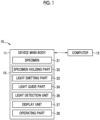
- a test device 10 is provided with a device main body 11 and a computer 12, and performs optical measurement on a test target 13 (refer to Fig. 2 ).
- a test target 13 (refer to Fig. 2 ).
- the present embodiment an example in which the presence or absence of contamination by endotoxin is tested by performing optical measurement, and if necessary, the content or concentration of endotoxin is measured will be described.
- the test target 13 is a solution in which a lysate reagent and a tested object are mixed.
- the tested object is an injection such as a vaccine or a blood preparation, water obtained by recovering endotoxin from the tested object such as a syringe or an injection needle, polyethylene glycol, ethylenediamine tetraacetic acid (so-called recovery liquid), or blood or body fluid collected from a patient who may be infected with Gram-negative bacteria or fungi, or the like.
- the lysate reagent is Limulus Amebocyte Lysate (LAL) or Tachypleus Amebocyte Lysate (TAL).
- the lysate reagent prepared from horseshoe crab blood cell extract can also be used for measuring (1 ⁇ 3) - ⁇ -D-glucan present on the cell wall of fungi, depending on the adjustment of the reagent components.
- the lysate reagent is used in a test to determine the presence or absence of fungal infection by measuring the concentration of (1 ⁇ 3) - ⁇ -D-glucan in the patient's blood or body fluid.
- endotoxin may be read as (1 ⁇ 3) - ⁇ -D-glucan
- the test device 10 for endotoxin test also functions as a (1 ⁇ 3) - ⁇ -D-glucan test device.
- one test device 10 can perform test of both endotoxin and (1 ⁇ 3) - ⁇ -D-glucan.
- the device main body 11 is a portion of the test device 10 including a measuring unit 15 for performing optical measurement of the test target 13.
- the device main body 11 is provided with a specimen 21, a specimen holding part 22, a light emitting part 23, a light guide part 24, a light detection unit 26, a display unit 27, an operating part 28, and the like.
- the specimen holding part 22, the light emitting part 23, the light guide part 24, and the light detection unit 26 constitute the measuring unit 15.
- the specimen 21 is a container that accommodates the test target 13 and is mounted on the specimen holding part 22.
- the specimen 21 is formed in a cylindrical shape with one closed end, and is mounted on the specimen holding part 22 in a posture in which the longitudinal direction (direction of the axis of the cylinder) is parallel to the vertical direction and the closed end faces downward.
- the specimen 21 has a circular cross section.
- the cross section in the horizontal direction is circular in a state of being mounted on the measuring unit 15.
- the circular cross section means that the outer shape of the cross section is a circle, an ellipse, or a substantially smooth closed curve similar thereto.
- the specimen 21 is made of heat-resistant glass.
- the reason why the specimen 21 is made of heat-resistant glass is to prevent the specimen 21 before accommodating the test target from containing endotoxin and (1 ⁇ 3) - ⁇ -D-glucan, for example, by the dry heat sterilization treatment at 250°C or higher and 30 minutes or longer.
- the specimen holding part 22 holds a plurality of specimens 21 side by side.
- the specimen holding part 22 has a plurality of openings 31 (opening portions) arranged in a row in the Y direction.
- the openings 31 are elongated in the vertical direction (Z direction), and by inserting the specimens 21 into each of the openings 31, the specimens 21 are held in a row.
- the specimen holding part 22 has six openings 31, and by inserting the specimen 21 into all of these openings, six specimens 21 can be held at the same time.
- the specimen holding part 22 may hold seven or more or five or less specimens 21.
- the specimen holding part 22 has a heater 32 on the lower surface (surface on the negative side in the Z direction).
- the temperature of the specimen holding part 22 and the specimen 21 held by the specimen holding part 22 can be maintained within a predetermined temperature or a predetermined temperature range. Therefore, the specimen holding part 22 also functions as a so-called constant-temperature tank.
- the light emitting part 23 irradiates the specimen 21 held by the specimen holding part 22 with light used for test.
- the light guide part 24 is formed in a rectangular tubular shape surrounding the optical path of light from the light emitting part 23 to the specimen 21.
- One opening end of the light guide part 24 is connected to the specimen holding part 22, and the other opening end is connected to the light emitting part 23.
- the light emitting part 23 is attached to the specimen holding part 22 via the light guide part 24.
- the light emitting part 23 is provided with a light emitting element 41V (first light emitting element), a light emitting element 41B (second light emitting element), and a light emitting element 41R (third light emitting element).
- These light emitting elements 41V, 41B, and 41R are, for example, light emitting diodes (LEDs), and irradiate the specimen 21 with light by emitting light.
- the light emitting elements 41V, 41B, and 41R irradiate the specimen 21 with light in the horizontal direction.
- the specimen holding part 22 is provided with an opening 42 having a range in which at least the specimen 21 is exposed to the light emitting elements 41V, 41B, and 41R side between the specimen 21 and the light emitting elements 41V, 41B, and 41R. Therefore, the light from the light emitting elements 41V, 41B, and 41R is horizontally incident on the specimen 21 through the opening 42.
- the light emitting element 41R is used, for example, in a case of testing by a turbidimetric method, and the light emitted by the light emitting element 41R is, for example, red.
- one light emitting element 41R is provided for each specimen 21.
- the light emitting element 41R is provided substantially in front of each specimen 21.
- the front of the specimen 21 is a position where the optical axis is parallel to the X direction (direction perpendicular to the Y direction (direction where the specimens 21 are arranged)) and passes through the center of the specimen 21.
- the light emitting elements 41V and 41B are selected and used, for example, in a case of performing a test by a colorimetric method.
- the light emitted by the light emitting element 41V is, for example, purple
- the light emitted by the light emitting element 41B is, for example, blue.
- the light emitting elements 41V and 41B are alternately arranged at a constant pitch with the light emitting element 41R interposed therebetween in the Y direction (direction where the specimens 21 are arranged).
- the light emitting elements 41V, 41B and 41R are arranged in the order of the light emitting element 41V, the light emitting element 41R, the light emitting element 41B, the light emitting element 41R, the light emitting element 41V, the light emitting element 41R, the light emitting element 41B ⁇ in the Y direction at a constant pitch. That is, the light emitting element 41R is arranged at an intermediate point between the light emitting element 41V and the light emitting element 41B.
- one light emitting element 41V is provided for each of the two specimens 21, and the two specimens 21 are irradiated with light from one light emitting element 41V
- one light emitting element 41B is also provided for each of the two specimens 21, and the two specimens 21 are irradiated with light from one light emitting element 41B.
- the light emitting elements 41V and 41B are arranged in a non-frontal position of the specimen 21, and irradiate the specimen 21 with light from oblique directions inclined with respect to the optical axis of the light emitting element 41R.
- one light emitting element 41V may be provided for each specimen 21.
- one light emitting element 41B may be provided for each specimen 21.
- one light emitting element 41R may be provided for each specimen 21.
- the light detection unit 26 is provided with a light-receiving element 53 that receives light emitted from the light emitting elements 41V, 41B, and 41R and transmitted through the specimen 21 (test target) or scattered in a case of transmitting through the specimen 21 (test target 13).
- the light-receiving element 53 is, for example, an optical sensor such as a photo diode (PD), and is provided for each specimen 21.
- PD photo diode
- the specimen holding part 22 is provided with an opening 43 between the specimen 21 and the light-receiving element 53 having a range in which at least the light-receiving element 53 is exposed to the specimen 21 side. Therefore, the light transmitted through the specimen 21 reaches the light-receiving element 53 through the opening 43.
- the specimen holding part 22 is provided with a specimen pressing part 60.
- the specimen pressing part 60 is provided with a biasing member 61 and a pressing member 62, which are housed in a case 63.
- the specimen pressing part 60 is attached to the specimen holding part 22.
- one set of the biasing member 61 and the pressing member 62 is provided for one opening 31 (opening 31 on which the specimen 21 is mounted). That is, in the present embodiment, six sets of the biasing member 61 and the pressing member 62 are provided.
- one case 63 accommodates three sets of the biasing member 61 and the pressing member 62. That is, two cases 63 are provided in the present embodiment.
- the pressing member 62 is provided with a pressing end 62B at one end of a shaft 62A.
- the pressing end 62B is made of a material having sliding property such as polyoxymethylene (POM).
- POM polyoxymethylene
- the tip part of the pressing end 62B is spherical, but as shown in Fig. 6 , the tip part of the pressing end 62B may be planar.
- tip of the pressing end 62B may be curved.
- the tip of the pressing end 62B is formed as a curved surface having a central projected shape
- Fig. 8 the tip of the pressing end 62B is formed as a curved surface having a central recessed shape.
- openings 64 and 65 are formed in the case 63, and the pressing member 62 is accommodated in the case 63 in a state where the shaft 62A projects from the opening 64 and the pressing end 62B projects from the opening 65, and is slidably supported in the Y direction (horizontal direction, the direction where the pressing end 62B projects from the opening 65 and the direction where the pressing end 62B is accommodated in the case 63).
- the biasing member 61 is a coil spring in the present embodiment, and biases the pressing member 62 in a direction where the pressing end 62B projects from the opening 65.
- the specimen pressing part 60 is provided on the side opposite to the light emitting part 23 across the opening 31 on which the specimen 21 is mounted.
- the pressing end 62B is biased toward the light emitting element 41R by the biasing member 61.
- An opening 66 is formed in the specimen holding part 22.
- the pressing member 62 causes the pressing end 62B to project through the openings 65 and 66 into the opening 31 on which the specimen 21 is mounted by the biasing of the biasing member 61.
- the specimen 21 is pressed toward the interior wall on the side opposite to the pressing member 62 (in the present embodiment, light emitting element 41R (interior wall on the light emitting element 41R side)) of the interior wall of the opening 31.
- the specimen 21 is supported in close contact with a predetermined position of the interior wall of the opening 31 (in the present embodiment, interior wall on the light emitting element 41R side).
- the pressing end 62B is pressed toward the inside of the case 63 by the specimen 21, and the pressing end 62B moves toward the inside of the case 63 against the biasing force of the biasing member 61.
- the specimen 21 can be mounted on the opening 31.
- by pulling the shaft 62A projecting from the opening 64 of the case 63 it is also possible to mount the specimen 21 in the opening 31 by moving the pressing end 62B toward the inside of the case 63 against the biasing force of the biasing member 61.
- the opening 31 for mounting the specimen 21 is formed to have an outer diameter one size larger than the specimen 21 in order to mount the specimen 21 smoothly, and by pressing the specimen 21 with the specimen pressing part 60 as described above, the specimen 21 does not rattle in the opening 31.
- the specimen 21 can be supported at a predetermined position of the opening 31 (in the present embodiment, position in close contact with the interior wall on the light emitting element 41R side of the interior wall of the opening 31). As a result, measurement (test) can be performed with high accuracy.
- the specimen 21 in a case where the specimen 21 rattles in the opening 31 or the position of the specimen 21 varies, due to the change in the state of refraction of light in a case of transmitting through the side wall of the specimen 21 (optical path of the light from the light emitting elements 41V, 41B, and 41R to the light-receiving element 53 changes), there arises a problem that measurement results are different from each other even in the same specimen 21, and/or a problem that the measurement error increases.
- the specimen 21 is pressed by the specimen pressing part 60 to be supported at a predetermined position in the opening 31, so the above-described problem can be prevented.
- both the specimen 21 and the opening 31 on which the specimen 21 is mounted have a circular cross section. Therefore, it is possible to prevent variations in the movement destination (support position of the specimen 21) in a case where the specimen 21 is pressed. In other words, the specimen 21 is pushed and moves in a direction from the pressing member 62 to be supported at the movement destination, since both the specimen 21 and the opening 31 have circular cross sections, the movement destination in a case where the specimen 21 is pressed is limited to one point of the interior wall of the opening 31 that is farthest from the pressing member 62. By supporting the specimen 21 at one limited point (preventing variations in the support position of the specimen 21), more accurate measurement (test) can be performed.
- the display unit 27 is, for example, an indicator indicating whether or not the test can be executed and/or the progress of the test.
- the display unit 27 can be a display screen such as a liquid crystal panel, or a touch panel or the like.
- the operating part 28 is a switch or the like for directly giving an operation instruction to the device main body 11.
- the display unit 27 is a touch panel
- at least a part of the operating part 28 can be formed by using a graphical user interface displayed on the touch panel.
- the computer 12 is a part of the test device 10 that controls each part of the device main body 11 and performs analysis or determination using measurement data (signals and the like acquired from the light-receiving element 53) acquired from the device main body 11. Specifically, the computer 12 acquires the measurement data from the measuring unit 15 and analyzes or the like using the measurement data to determine the presence or absence of endotoxin or to generate data that can determine the presence or absence of endotoxin.
- the computer 12 is provided separately from the device main body 11, but a part or all of the functions of the computer 12 can be incorporated into the device main body 11.
- the colorimetric method is a test method of identifying the presence or absence of endotoxin by measuring the activation of the lysate reagent by endotoxin by the absorbance at a specific wavelength. Since the measuring unit 15 is provided with two types of light emitting elements, the light emitting element 41V and the light emitting element 41B, for test by the colorimetric method, the test accuracy can be improved by subtracting the disturbance other than the colorimetric reaction by using both of the light emitting elements.
- the turbidimetric method is a test method of identifying the presence or absence of endotoxin by measuring the change in turbidity of a sample gelled by activation of a lysate reagent by endotoxin.
- the light emitting element 41 for each specimen 21 is used.
- the specimen 21 is pressed by the pressing member 62 and supported at a predetermined position in the opening 31, so that measurement (test) can be performed with high accuracy.
- the test device 10 performs an endotoxin test, but the present invention can be used for a device that performs a test other than the endotoxin test for detecting transmitted light, scattered light, or the like.
- the test device 10 includes one measuring unit 15 in the above embodiment, the test device 10 may include a plurality of measuring units 15 in the device main body 11.
Landscapes
- Physics & Mathematics (AREA)
- Health & Medical Sciences (AREA)
- Life Sciences & Earth Sciences (AREA)
- Chemical & Material Sciences (AREA)
- Analytical Chemistry (AREA)
- Biochemistry (AREA)
- General Health & Medical Sciences (AREA)
- General Physics & Mathematics (AREA)
- Immunology (AREA)
- Pathology (AREA)
- Spectroscopy & Molecular Physics (AREA)
- Investigating Or Analysing Materials By Optical Means (AREA)
- Optical Measuring Cells (AREA)
Abstract
Description
- The present invention relates to a test device that includes a light emitting element that illuminates a test target and a light-receiving element that receives light from the test target, and that inspects the test target using light.
-
JP2006-322854A JP2006-322854A - However, in a case where the sensor unit is pressed against the measurement stage as in above-described
JP2006-322854A - The present invention has been made in view of the above background, and an object thereof is to provide a test device capable of improving test accuracy.
- In order to achieve the above object, a test device according to an aspect of the present invention comprises a specimen with a circular cross section that accommodates a test target, a specimen holding part that has an opening portion with a circular cross section and holds the specimen, a plurality of light emitting elements that irradiate the specimen with light from a plurality of directions, a light-receiving element that faces the light emitting element through the specimen, and a pressing member that projects from an interior wall of the opening portion into the opening portion to press the specimen and press the specimen against the interior wall on an opposite side.
- A first light emitting element and a second light emitting element may be provided as the light emitting elements, and the pressing member may press the specimen toward an intermediate point between the first light emitting element and the second light emitting element.
- A third light emitting element disposed at the intermediate point between the first light emitting element and the second light emitting element may be provided as the light emitting element, and the pressing member may press the specimen toward the third light emitting element.
- Each of the light emitting elements may have a mutually different emission color.
- The specimen holding part may include a plurality of opening portions and hold a plurality of specimens.
- The specimen may be formed long in a direction perpendicular to the cross section, and the specimen holding part may hold the plurality of specimens arranged in a horizontal direction in a posture in which a longitudinal direction is vertical.
- The specimen may be formed in a cylindrical shape with one closed end.
- The light emitting elements may be arranged in the horizontal direction.
- The light emitting element may cause light to be incident on the specimen horizontally.
- The pressing member may press the specimen in the horizontal direction.
- According to the test device of the embodiment of the present invention, since the specimen accommodating the test target is pressed against the specimen holding part, test accuracy can be improved.
-
-
Fig. 1 is a block diagram showing a configuration of a test device. -
Fig. 2 is a perspective view of a measuring unit and a specimen. -
Fig. 3 is a cross-sectional view of the measuring unit. -
Fig. 4 is a cross-sectional view of the measuring unit. -
Fig. 5 is an external perspective view of a pressing member. -
Fig. 6 is an external perspective view of the pressing member. -
Fig. 7 is an external perspective view of the pressing member. -
Fig. 8 is an external perspective view of the pressing member. - As shown in
Fig. 1 , a test device 10 is provided with a devicemain body 11 and acomputer 12, and performs optical measurement on a test target 13 (refer toFig. 2 ). In the present embodiment, an example in which the presence or absence of contamination by endotoxin is tested by performing optical measurement, and if necessary, the content or concentration of endotoxin is measured will be described. - In the present embodiment, the
test target 13 is a solution in which a lysate reagent and a tested object are mixed. For example, the tested object is an injection such as a vaccine or a blood preparation, water obtained by recovering endotoxin from the tested object such as a syringe or an injection needle, polyethylene glycol, ethylenediamine tetraacetic acid (so-called recovery liquid), or blood or body fluid collected from a patient who may be infected with Gram-negative bacteria or fungi, or the like. The lysate reagent is Limulus Amebocyte Lysate (LAL) or Tachypleus Amebocyte Lysate (TAL). - The lysate reagent prepared from horseshoe crab blood cell extract can also be used for measuring (1 → 3) -β-D-glucan present on the cell wall of fungi, depending on the adjustment of the reagent components. The lysate reagent is used in a test to determine the presence or absence of fungal infection by measuring the concentration of (1 → 3) -β-D-glucan in the patient's blood or body fluid. In the present specification, in a case of being described as endotoxin, endotoxin may be read as (1 → 3) -β-D-glucan, and the test device 10 for endotoxin test also functions as a (1 → 3) -β-D-glucan test device. In addition, one test device 10 can perform test of both endotoxin and (1 → 3) -β-D-glucan.
- The device
main body 11 is a portion of the test device 10 including ameasuring unit 15 for performing optical measurement of thetest target 13. Specifically, the devicemain body 11 is provided with aspecimen 21, aspecimen holding part 22, alight emitting part 23, alight guide part 24, alight detection unit 26, adisplay unit 27, anoperating part 28, and the like. Of these, thespecimen holding part 22, thelight emitting part 23, thelight guide part 24, and thelight detection unit 26 constitute themeasuring unit 15. - As shown in
Fig. 2 , thespecimen 21 is a container that accommodates thetest target 13 and is mounted on thespecimen holding part 22. In the present embodiment, thespecimen 21 is formed in a cylindrical shape with one closed end, and is mounted on thespecimen holding part 22 in a posture in which the longitudinal direction (direction of the axis of the cylinder) is parallel to the vertical direction and the closed end faces downward. In this manner, thespecimen 21 has a circular cross section. Specifically, the cross section in the horizontal direction is circular in a state of being mounted on themeasuring unit 15. The circular cross section means that the outer shape of the cross section is a circle, an ellipse, or a substantially smooth closed curve similar thereto. - In the present embodiment, the
specimen 21 is made of heat-resistant glass. The reason why thespecimen 21 is made of heat-resistant glass is to prevent thespecimen 21 before accommodating the test target from containing endotoxin and (1 → 3) -β-D-glucan, for example, by the dry heat sterilization treatment at 250°C or higher and 30 minutes or longer. - The
specimen holding part 22 holds a plurality ofspecimens 21 side by side. Thespecimen holding part 22 has a plurality of openings 31 (opening portions) arranged in a row in the Y direction. Theopenings 31 are elongated in the vertical direction (Z direction), and by inserting thespecimens 21 into each of theopenings 31, thespecimens 21 are held in a row. In the present embodiment, thespecimen holding part 22 has sixopenings 31, and by inserting thespecimen 21 into all of these openings, sixspecimens 21 can be held at the same time. Thespecimen holding part 22 may hold seven or more or five orless specimens 21. In addition, thespecimen holding part 22 has aheater 32 on the lower surface (surface on the negative side in the Z direction). By controlling the on and off of theheater 32, the temperature of thespecimen holding part 22 and thespecimen 21 held by thespecimen holding part 22 can be maintained within a predetermined temperature or a predetermined temperature range. Therefore, thespecimen holding part 22 also functions as a so-called constant-temperature tank. - As shown in
Fig. 3 , thelight emitting part 23 irradiates thespecimen 21 held by thespecimen holding part 22 with light used for test. Thelight guide part 24 is formed in a rectangular tubular shape surrounding the optical path of light from thelight emitting part 23 to thespecimen 21. One opening end of thelight guide part 24 is connected to thespecimen holding part 22, and the other opening end is connected to thelight emitting part 23. Thelight emitting part 23 is attached to thespecimen holding part 22 via thelight guide part 24. - The
light emitting part 23 is provided with alight emitting element 41V (first light emitting element), alight emitting element 41B (second light emitting element), and alight emitting element 41R (third light emitting element). Theselight emitting elements specimen 21 with light by emitting light. In the present embodiment, thelight emitting elements specimen 21 with light in the horizontal direction. Thespecimen holding part 22 is provided with anopening 42 having a range in which at least thespecimen 21 is exposed to thelight emitting elements specimen 21 and thelight emitting elements light emitting elements specimen 21 through theopening 42. - The
light emitting element 41R is used, for example, in a case of testing by a turbidimetric method, and the light emitted by thelight emitting element 41R is, for example, red. In the present embodiment, onelight emitting element 41R is provided for eachspecimen 21. In addition, in the present embodiment, thelight emitting element 41R is provided substantially in front of eachspecimen 21. The front of thespecimen 21 is a position where the optical axis is parallel to the X direction (direction perpendicular to the Y direction (direction where thespecimens 21 are arranged)) and passes through the center of thespecimen 21. - The
light emitting elements light emitting element 41V is, for example, purple, and the light emitted by thelight emitting element 41B is, for example, blue. In the present embodiment, thelight emitting elements light emitting element 41R interposed therebetween in the Y direction (direction where thespecimens 21 are arranged). Specifically, thelight emitting elements light emitting element 41V, thelight emitting element 41R, thelight emitting element 41B, thelight emitting element 41R, thelight emitting element 41V, thelight emitting element 41R, thelight emitting element 41B··· in the Y direction at a constant pitch. That is, thelight emitting element 41R is arranged at an intermediate point between the light emittingelement 41V and thelight emitting element 41B. - In addition, in the present embodiment, one
light emitting element 41V is provided for each of the twospecimens 21, and the twospecimens 21 are irradiated with light from onelight emitting element 41V Similarly, onelight emitting element 41B is also provided for each of the twospecimens 21, and the twospecimens 21 are irradiated with light from onelight emitting element 41B. In this manner, unlike thelight emitting element 41R, thelight emitting elements specimen 21, and irradiate thespecimen 21 with light from oblique directions inclined with respect to the optical axis of thelight emitting element 41R. - Although the example in which two
specimens 21 are irradiated with light from onelight emitting element 41V has been described, onelight emitting element 41V may be provided for eachspecimen 21. In addition, although the example in which twospecimens 21 are irradiated with light from onelight emitting element 41B has been described, onelight emitting element 41B may be provided for eachspecimen 21. Furthermore, although the example in which onelight emitting element 41R is provided for eachspecimen 21 has been described, a configuration may be adopted in which a plurality ofspecimens 21 are irradiated with light from onelight emitting element 41R. - The
light detection unit 26 is provided with a light-receivingelement 53 that receives light emitted from thelight emitting elements element 53 is, for example, an optical sensor such as a photo diode (PD), and is provided for eachspecimen 21. In the present embodiment, since thespecimen holding part 22 holds sixspecimens 21, thelight detection unit 26 is provided with the light-receivingelement 53 at a position where the light transmitted through each of thesespecimens 21 can be received. In addition, thespecimen holding part 22 is provided with anopening 43 between thespecimen 21 and the light-receivingelement 53 having a range in which at least the light-receivingelement 53 is exposed to thespecimen 21 side. Therefore, the light transmitted through thespecimen 21 reaches the light-receivingelement 53 through theopening 43. - Returning to
Fig. 2 , thespecimen holding part 22 is provided with aspecimen pressing part 60. As shown inFig. 4 , thespecimen pressing part 60 is provided with a biasingmember 61 and a pressingmember 62, which are housed in acase 63. By attaching thecase 63 to thespecimen holding part 22, thespecimen pressing part 60 is attached to thespecimen holding part 22. In the present embodiment, one set of the biasingmember 61 and the pressingmember 62 is provided for one opening 31 (opening 31 on which thespecimen 21 is mounted). That is, in the present embodiment, six sets of the biasingmember 61 and the pressingmember 62 are provided. In addition, in the present embodiment, onecase 63 accommodates three sets of the biasingmember 61 and the pressingmember 62. That is, twocases 63 are provided in the present embodiment. - The pressing
member 62 is provided with apressing end 62B at one end of ashaft 62A. Thepressing end 62B is made of a material having sliding property such as polyoxymethylene (POM). As shown inFig. 5 , in the present embodiment, the tip part of thepressing end 62B is spherical, but as shown inFig. 6 , the tip part of thepressing end 62B may be planar. In addition, as shown inFigs. 7 and 8 , tip of thepressing end 62B may be curved. InFig. 7 , the tip of thepressing end 62B is formed as a curved surface having a central projected shape, and inFig. 8 , the tip of thepressing end 62B is formed as a curved surface having a central recessed shape. - Returning to
Fig. 4 ,openings case 63, and the pressingmember 62 is accommodated in thecase 63 in a state where theshaft 62A projects from theopening 64 and thepressing end 62B projects from theopening 65, and is slidably supported in the Y direction (horizontal direction, the direction where thepressing end 62B projects from theopening 65 and the direction where thepressing end 62B is accommodated in the case 63). The biasingmember 61 is a coil spring in the present embodiment, and biases the pressingmember 62 in a direction where thepressing end 62B projects from theopening 65. In the present embodiment, thespecimen pressing part 60 is provided on the side opposite to thelight emitting part 23 across theopening 31 on which thespecimen 21 is mounted. In the present embodiment, thepressing end 62B is biased toward thelight emitting element 41R by the biasingmember 61. - An
opening 66 is formed in thespecimen holding part 22. The pressingmember 62 causes thepressing end 62B to project through theopenings opening 31 on which thespecimen 21 is mounted by the biasing of the biasingmember 61. Thespecimen 21 is pressed toward the interior wall on the side opposite to the pressing member 62 (in the present embodiment, light emittingelement 41R (interior wall on thelight emitting element 41R side)) of the interior wall of theopening 31. As a result, thespecimen 21 is supported in close contact with a predetermined position of the interior wall of the opening 31 (in the present embodiment, interior wall on thelight emitting element 41R side). In a case where thespecimen 21 is mounted on theopening 31, thepressing end 62B is pressed toward the inside of thecase 63 by thespecimen 21, and thepressing end 62B moves toward the inside of thecase 63 against the biasing force of the biasingmember 61. As a result, thespecimen 21 can be mounted on theopening 31. In addition, by pulling theshaft 62A projecting from theopening 64 of thecase 63, it is also possible to mount thespecimen 21 in theopening 31 by moving thepressing end 62B toward the inside of thecase 63 against the biasing force of the biasingmember 61. - The
opening 31 for mounting thespecimen 21 is formed to have an outer diameter one size larger than thespecimen 21 in order to mount thespecimen 21 smoothly, and by pressing thespecimen 21 with thespecimen pressing part 60 as described above, thespecimen 21 does not rattle in theopening 31. In addition, thespecimen 21 can be supported at a predetermined position of the opening 31 (in the present embodiment, position in close contact with the interior wall on thelight emitting element 41R side of the interior wall of the opening 31). As a result, measurement (test) can be performed with high accuracy. - That is, in a case where the
specimen 21 rattles in theopening 31 or the position of thespecimen 21 varies, due to the change in the state of refraction of light in a case of transmitting through the side wall of the specimen 21 (optical path of the light from thelight emitting elements element 53 changes), there arises a problem that measurement results are different from each other even in thesame specimen 21, and/or a problem that the measurement error increases. On the other hand, in the test device 10 of the embodiment of the present invention, thespecimen 21 is pressed by thespecimen pressing part 60 to be supported at a predetermined position in theopening 31, so the above-described problem can be prevented. - In addition, in the test device 10 of the embodiment of the present invention, both the
specimen 21 and theopening 31 on which thespecimen 21 is mounted have a circular cross section. Therefore, it is possible to prevent variations in the movement destination (support position of the specimen 21) in a case where thespecimen 21 is pressed. In other words, thespecimen 21 is pushed and moves in a direction from the pressingmember 62 to be supported at the movement destination, since both thespecimen 21 and theopening 31 have circular cross sections, the movement destination in a case where thespecimen 21 is pressed is limited to one point of the interior wall of theopening 31 that is farthest from the pressingmember 62. By supporting thespecimen 21 at one limited point (preventing variations in the support position of the specimen 21), more accurate measurement (test) can be performed. - Returning to
Fig. 1 , thedisplay unit 27 is, for example, an indicator indicating whether or not the test can be executed and/or the progress of the test. In addition, thedisplay unit 27 can be a display screen such as a liquid crystal panel, or a touch panel or the like. - The operating
part 28 is a switch or the like for directly giving an operation instruction to the devicemain body 11. In a case where thedisplay unit 27 is a touch panel, at least a part of the operatingpart 28 can be formed by using a graphical user interface displayed on the touch panel. - The
computer 12 is a part of the test device 10 that controls each part of the devicemain body 11 and performs analysis or determination using measurement data (signals and the like acquired from the light-receiving element 53) acquired from the devicemain body 11. Specifically, thecomputer 12 acquires the measurement data from the measuringunit 15 and analyzes or the like using the measurement data to determine the presence or absence of endotoxin or to generate data that can determine the presence or absence of endotoxin. In the present embodiment, thecomputer 12 is provided separately from the devicemain body 11, but a part or all of the functions of thecomputer 12 can be incorporated into the devicemain body 11. - In the test device 10, endotoxin test by a colorimetric method and a turbidimetric method can be performed. The colorimetric method is a test method of identifying the presence or absence of endotoxin by measuring the activation of the lysate reagent by endotoxin by the absorbance at a specific wavelength. Since the measuring
unit 15 is provided with two types of light emitting elements, thelight emitting element 41V and thelight emitting element 41B, for test by the colorimetric method, the test accuracy can be improved by subtracting the disturbance other than the colorimetric reaction by using both of the light emitting elements. The turbidimetric method is a test method of identifying the presence or absence of endotoxin by measuring the change in turbidity of a sample gelled by activation of a lysate reagent by endotoxin. In the test by the turbidimetric method, the light emitting element 41 for eachspecimen 21 is used. - As described above, in the test device 10, the
specimen 21 is pressed by the pressingmember 62 and supported at a predetermined position in theopening 31, so that measurement (test) can be performed with high accuracy. - In the above embodiment, the test device 10 performs an endotoxin test, but the present invention can be used for a device that performs a test other than the endotoxin test for detecting transmitted light, scattered light, or the like. In addition, although the test device 10 includes one measuring
unit 15 in the above embodiment, the test device 10 may include a plurality of measuringunits 15 in the devicemain body 11. -
- 10: test device
- 11: device main body
- 12: computer
- 13: test target
- 15: measuring unit
- 21: specimen
- 22: specimen holding part
- 23: light emitting part
- 24: light guide part
- 26: light detection unit
- 27: display unit
- 28: operating part
- 31: opening (opening portion)
- 32: heater
- 41V: light emitting element (first light emitting element)
- 41B light emitting element (second light emitting element)
- 41R: light emitting element (third light emitting element)
- 42: opening
- 43: opening
- 53: light-receiving element
- 60: specimen pressing part
- 61: biasing member
- 62: pressing member
- 62A: shaft
- 62B: pressing end
- 63: case
- 64: opening
- 65: opening
- 66: opening
Claims (10)
- A test device comprising:a specimen with a circular cross section that accommodates a test target;a specimen holding part that has an opening portion with a circular cross section and holds the specimen;a plurality of light emitting elements that irradiate the specimen with light from a plurality of directions;a light-receiving element that faces the light emitting element through the specimen; anda pressing member that projects from an interior wall of the opening portion into the opening portion to press the specimen and press the specimen against the interior wall on an opposite side.
- The test device according to claim 1, further comprising:a first light emitting element and a second light emitting element as the light emitting elements,wherein the pressing member presses the specimen toward an intermediate point between the first light emitting element and the second light emitting element.
- The test device according to claim 2, further comprising:a third light emitting element disposed at the intermediate point between the first light emitting element and the second light emitting element as the light emitting element,wherein the pressing member presses the specimen toward the third light emitting element.
- The test device according to any one of claims 1 to 3,
wherein each of the light emitting elements has a mutually different emission color. - The test device according to any one of claims 1 to 4,
wherein the specimen holding part includes a plurality of the opening portions and holds a plurality of the specimens. - The test device according to claim 5,wherein the specimen is formed long in a direction perpendicular to the cross section, andthe specimen holding part holds the plurality of specimens arranged in a horizontal direction in a posture in which a longitudinal direction is vertical.
- The test device according to claim 6,
wherein the specimen is formed in a cylindrical shape with one closed end. - The test device according to claim 6 or 7,
wherein the light emitting elements are arranged in the horizontal direction. - The test device according to claim 8,
wherein the light emitting element causes light to be incident on the specimen horizontally. - The test device according to claim 9,
wherein the pressing member presses the specimen in the horizontal direction.
Applications Claiming Priority (2)
| Application Number | Priority Date | Filing Date | Title |
|---|---|---|---|
| JP2020085897 | 2020-05-15 | ||
| PCT/JP2021/011185 WO2021229915A1 (en) | 2020-05-15 | 2021-03-18 | Inspection device |
Publications (2)
| Publication Number | Publication Date |
|---|---|
| EP4151986A1 true EP4151986A1 (en) | 2023-03-22 |
| EP4151986A4 EP4151986A4 (en) | 2023-07-05 |
Family
ID=78525717
Family Applications (1)
| Application Number | Title | Priority Date | Filing Date |
|---|---|---|---|
| EP21805005.2A Pending EP4151986A4 (en) | 2020-05-15 | 2021-03-18 | Inspection device |
Country Status (4)
| Country | Link |
|---|---|
| US (1) | US20230077006A1 (en) |
| EP (1) | EP4151986A4 (en) |
| JP (1) | JP7539977B2 (en) |
| WO (1) | WO2021229915A1 (en) |
Family Cites Families (12)
| Publication number | Priority date | Publication date | Assignee | Title |
|---|---|---|---|---|
| US3977794A (en) * | 1974-07-15 | 1976-08-31 | Coulter Electronics, Inc. | Universal cell holder |
| JPS58140459U (en) * | 1982-03-17 | 1983-09-21 | 株式会社常光 | Laserne fluorometer |
| JPH0515082Y2 (en) * | 1986-04-30 | 1993-04-21 | ||
| US6836332B2 (en) | 2001-09-25 | 2004-12-28 | Tennessee Scientific, Inc. | Instrument and method for testing fluid characteristics |
| JP2004093536A (en) | 2002-09-04 | 2004-03-25 | Daicen Membrane Systems Ltd | Simple measuring instrument for endotoxin concentration |
| EP1825317B1 (en) * | 2004-11-24 | 2013-04-17 | Battelle Memorial Institute | Optical system for cell imaging |
| JP2006322854A (en) | 2005-05-19 | 2006-11-30 | Fujifilm Holdings Corp | Measuring instrument utilizing total reflection damping, and pressing quantity adjusting method using it |
| JP5308150B2 (en) | 2006-03-14 | 2013-10-09 | Gast Japan 株式会社 | Soil inspection equipment |
| JP5010180B2 (en) * | 2006-05-31 | 2012-08-29 | 京セラドキュメントソリューションズ株式会社 | Liquid developer concentration measuring apparatus and wet image forming apparatus having the same |
| CN103674858B (en) | 2013-09-18 | 2016-04-20 | 江西科益茶业有限公司 | A kind of tea soup look method for quick and device |
| JP2018128604A (en) | 2017-02-09 | 2018-08-16 | オリンパス株式会社 | Microscope device |
| EP3651905B9 (en) * | 2017-07-14 | 2025-10-29 | MEON Medical Solutions GmbH & Co KG | Automatic analyzer and method for carrying out chemical, biochemical and/or immunochemical analyses |
-
2021
- 2021-03-18 EP EP21805005.2A patent/EP4151986A4/en active Pending
- 2021-03-18 WO PCT/JP2021/011185 patent/WO2021229915A1/en not_active Ceased
- 2021-03-18 JP JP2022522536A patent/JP7539977B2/en active Active
-
2022
- 2022-11-15 US US18/055,582 patent/US20230077006A1/en not_active Abandoned
Also Published As
| Publication number | Publication date |
|---|---|
| WO2021229915A1 (en) | 2021-11-18 |
| JPWO2021229915A1 (en) | 2021-11-18 |
| US20230077006A1 (en) | 2023-03-09 |
| JP7539977B2 (en) | 2024-08-26 |
| EP4151986A4 (en) | 2023-07-05 |
Similar Documents
| Publication | Publication Date | Title |
|---|---|---|
| US5066859A (en) | Hematocrit and oxygen saturation blood analyzer | |
| US5249584A (en) | Syringe for hematocrit and oxygen saturation blood analyzer | |
| US8150114B2 (en) | Method for ensuring quality of a sample carrier | |
| US6803594B2 (en) | Measuring system for optically determining concentration of turbid liquid samples | |
| EP2112514A1 (en) | Method and apparatus for checking the fluid in a pipet tip | |
| JPH10153597A (en) | Method for determining existence of serum variable | |
| US20100216223A1 (en) | Reagent preparing device, specimen measuring device and reagent preparing method | |
| JP7206570B2 (en) | Analysis equipment | |
| JP6524305B2 (en) | Apparatus and method for determining blood settling velocity and other parameters associated therewith | |
| CN106471356B (en) | Automatic analysis device | |
| CN108508006A (en) | A kind of portable detector | |
| EP1185852A1 (en) | Method and apparatus for examining fluids of biological origin | |
| JPH058975B2 (en) | ||
| US20230077006A1 (en) | Test device | |
| US12111314B2 (en) | Test device | |
| LU102997B1 (en) | Optical analyte sensor | |
| TW200307127A (en) | Body-fluid censoring unit | |
| CN207798645U (en) | A special detection device for urine iodine analyzer | |
| KR20250074523A (en) | A device that tests light absorption and conductivity that also includes heating and temperature detection functions in a liquid. | |
| CN223308097U (en) | Multifunctional detection device and multifunctional detection instrument | |
| KR102472080B1 (en) | Portable fiber optics localized surface plasmon resonance measuring apparatus for ultra precise measurement | |
| CN214584909U (en) | A portable fluorescent trace element detector | |
| CN110907418A (en) | Device for detecting optical characteristics of liquid sample in pipette head |
Legal Events
| Date | Code | Title | Description |
|---|---|---|---|
| STAA | Information on the status of an ep patent application or granted ep patent |
Free format text: STATUS: THE INTERNATIONAL PUBLICATION HAS BEEN MADE |
|
| PUAI | Public reference made under article 153(3) epc to a published international application that has entered the european phase |
Free format text: ORIGINAL CODE: 0009012 |
|
| STAA | Information on the status of an ep patent application or granted ep patent |
Free format text: STATUS: REQUEST FOR EXAMINATION WAS MADE |
|
| 17P | Request for examination filed |
Effective date: 20221111 |
|
| AK | Designated contracting states |
Kind code of ref document: A1 Designated state(s): AL AT BE BG CH CY CZ DE DK EE ES FI FR GB GR HR HU IE IS IT LI LT LU LV MC MK MT NL NO PL PT RO RS SE SI SK SM TR |
|
| REG | Reference to a national code |
Ref country code: DE Ref legal event code: R079 Free format text: PREVIOUS MAIN CLASS: G01N0021010000 Ipc: G01N0021510000 |
|
| A4 | Supplementary search report drawn up and despatched |
Effective date: 20230607 |
|
| RIC1 | Information provided on ipc code assigned before grant |
Ipc: G01N 21/78 20060101ALN20230601BHEP Ipc: B01L 9/06 20060101ALI20230601BHEP Ipc: G01N 21/01 20060101ALI20230601BHEP Ipc: G01N 21/25 20060101ALI20230601BHEP Ipc: G01N 21/51 20060101AFI20230601BHEP |
|
| DAV | Request for validation of the european patent (deleted) | ||
| DAX | Request for extension of the european patent (deleted) | ||
| STAA | Information on the status of an ep patent application or granted ep patent |
Free format text: STATUS: EXAMINATION IS IN PROGRESS |
|
| 17Q | First examination report despatched |
Effective date: 20250514 |