EP4151973A1 - Dispositif d'essai d'au moins un élément enfichable - Google Patents
Dispositif d'essai d'au moins un élément enfichable Download PDFInfo
- Publication number
- EP4151973A1 EP4151973A1 EP22193660.2A EP22193660A EP4151973A1 EP 4151973 A1 EP4151973 A1 EP 4151973A1 EP 22193660 A EP22193660 A EP 22193660A EP 4151973 A1 EP4151973 A1 EP 4151973A1
- Authority
- EP
- European Patent Office
- Prior art keywords
- plug
- test
- axis
- force
- compensating
- Prior art date
- Legal status (The legal status is an assumption and is not a legal conclusion. Google has not performed a legal analysis and makes no representation as to the accuracy of the status listed.)
- Pending
Links
Images

Classifications
-
- H—ELECTRICITY
- H01—ELECTRIC ELEMENTS
- H01R—ELECTRICALLY-CONDUCTIVE CONNECTIONS; STRUCTURAL ASSOCIATIONS OF A PLURALITY OF MUTUALLY-INSULATED ELECTRICAL CONNECTING ELEMENTS; COUPLING DEVICES; CURRENT COLLECTORS
- H01R43/00—Apparatus or processes specially adapted for manufacturing, assembling, maintaining, or repairing of line connectors or current collectors or for joining electric conductors
- H01R43/26—Apparatus or processes specially adapted for manufacturing, assembling, maintaining, or repairing of line connectors or current collectors or for joining electric conductors for engaging or disengaging the two parts of a coupling device
-
- G—PHYSICS
- G01—MEASURING; TESTING
- G01R—MEASURING ELECTRIC VARIABLES; MEASURING MAGNETIC VARIABLES
- G01R1/00—Details of instruments or arrangements of the types included in groups G01R5/00 - G01R13/00 and G01R31/00
- G01R1/02—General constructional details
- G01R1/04—Housings; Supporting members; Arrangements of terminals
- G01R1/0408—Test fixtures or contact fields; Connectors or connecting adaptors; Test clips; Test sockets
- G01R1/0416—Connectors, terminals
-
- G—PHYSICS
- G01—MEASURING; TESTING
- G01L—MEASURING FORCE, STRESS, TORQUE, WORK, MECHANICAL POWER, MECHANICAL EFFICIENCY, OR FLUID PRESSURE
- G01L5/00—Apparatus for, or methods of, measuring force, work, mechanical power, or torque, specially adapted for specific purposes
- G01L5/0028—Force sensors associated with force applying means
- G01L5/0033—Force sensors associated with force applying means applying a pulling force
-
- G—PHYSICS
- G01—MEASURING; TESTING
- G01L—MEASURING FORCE, STRESS, TORQUE, WORK, MECHANICAL POWER, MECHANICAL EFFICIENCY, OR FLUID PRESSURE
- G01L5/00—Apparatus for, or methods of, measuring force, work, mechanical power, or torque, specially adapted for specific purposes
- G01L5/0028—Force sensors associated with force applying means
- G01L5/0038—Force sensors associated with force applying means applying a pushing force
-
- G—PHYSICS
- G01—MEASURING; TESTING
- G01L—MEASURING FORCE, STRESS, TORQUE, WORK, MECHANICAL POWER, MECHANICAL EFFICIENCY, OR FLUID PRESSURE
- G01L5/00—Apparatus for, or methods of, measuring force, work, mechanical power, or torque, specially adapted for specific purposes
- G01L5/0057—Apparatus for, or methods of, measuring force, work, mechanical power, or torque, specially adapted for specific purposes measuring forces due to spring-shaped elements
-
- G—PHYSICS
- G01—MEASURING; TESTING
- G01L—MEASURING FORCE, STRESS, TORQUE, WORK, MECHANICAL POWER, MECHANICAL EFFICIENCY, OR FLUID PRESSURE
- G01L5/00—Apparatus for, or methods of, measuring force, work, mechanical power, or torque, specially adapted for specific purposes
- G01L5/0061—Force sensors associated with industrial machines or actuators
- G01L5/0076—Force sensors associated with manufacturing machines
- G01L5/009—Force sensors associated with material gripping devices
-
- G—PHYSICS
- G01—MEASURING; TESTING
- G01M—TESTING STATIC OR DYNAMIC BALANCE OF MACHINES OR STRUCTURES; TESTING OF STRUCTURES OR APPARATUS, NOT OTHERWISE PROVIDED FOR
- G01M5/00—Investigating the elasticity of structures, e.g. deflection of bridges or air-craft wings
- G01M5/0041—Investigating the elasticity of structures, e.g. deflection of bridges or air-craft wings by determining deflection or stress
- G01M5/005—Investigating the elasticity of structures, e.g. deflection of bridges or air-craft wings by determining deflection or stress by means of external apparatus, e.g. test benches or portable test systems
-
- G—PHYSICS
- G01—MEASURING; TESTING
- G01R—MEASURING ELECTRIC VARIABLES; MEASURING MAGNETIC VARIABLES
- G01R31/00—Arrangements for testing electric properties; Arrangements for locating electric faults; Arrangements for electrical testing characterised by what is being tested not provided for elsewhere
- G01R31/50—Testing of electric apparatus, lines, cables or components for short-circuits, continuity, leakage current or incorrect line connections
- G01R31/66—Testing of connections, e.g. of plugs or non-disconnectable joints
-
- G—PHYSICS
- G02—OPTICS
- G02B—OPTICAL ELEMENTS, SYSTEMS OR APPARATUS
- G02B6/00—Light guides; Structural details of arrangements comprising light guides and other optical elements, e.g. couplings
- G02B6/24—Coupling light guides
- G02B6/36—Mechanical coupling means
- G02B6/38—Mechanical coupling means having fibre to fibre mating means
- G02B6/3807—Dismountable connectors, i.e. comprising plugs
- G02B6/3833—Details of mounting fibres in ferrules; Assembly methods; Manufacture
- G02B6/385—Accessories for testing or observation of connectors
Definitions
- the invention relates to a device for testing at least one plug-in element of a plug-in connection.
- the invention also relates to a method for testing plug-in elements of a plug-in connection.
- the invention further relates to the use of a compensation element according to the invention in a device for testing plug-in elements of a plug-in connection.
- the invention also relates to the production of a compensation element according to the invention for use in a device for testing plug-in elements of a plug-in connection.
- Connectors are used in a variety of applications.
- plug-in connections in the electrical industry are known as electrical plug-in connections in order to connect electrically conductive elements to one another and to establish electrical contact.
- plug-in connections are also known in other areas, for example in pipeline construction, in which two pipes are connected to one another by plugging them together and realizing a continuous pipeline.
- Plug-in elements are also known in the optical industry, for example for connecting optical lines.
- Optical lines are, for example, so-called glass fibers.
- plug-in connections In the electrical industry, connections between two plug-in elements, so-called plug-in connections, are often designed to be reversible, with a plug-in connection consisting of two plug-in elements is executed.
- a first plug-in element is connected to a further plug-in element by bringing them together. This process is also commonly referred to as plugging or plugging in.
- plug-in element is understood below to mean that a plug-in element produces a plug-in connection with a corresponding further plug-in element by bringing the plug-in element and further plug-in element together.
- the merging is generally a linear movement.
- the plug-in element is suitably aligned to produce a plug-in connection with the other plug-in element and is then brought together with a precise fit.
- the plug connection is often non-positively releasably fixed. This is done, for example, by a spring force which the plug-in element exerts on the other plug-in element.
- the additional plug-in element can exert a spring force on the plug-in element.
- a force must therefore be applied with which the plug-in element is pressed into the other plug-in element. This force is called the insertion force.
- the insertion force and extraction force vary depending on the application.
- low pull-out forces of a few 100 mN are known.
- Pull-out forces of several 100 N are also known for mechanically highly stressed plug connections. Pull-out forces are also known as part of DIN EN 60512-1-100_2012.
- the insertion force and extraction force for a plug connection do not deviate by more than an insertion force tolerance or extraction force tolerance from a nominal insertion force value or nominal extraction force value.
- the insertion force and/or extraction force for connectors must be checked.
- a plug-in element is inserted into another plug-in element and the force that occurs to join the plug-in connection is determined.
- the force determined in this connector test must be within a predetermined range specified for a high quality connector.
- a conductor insertion end is inserted as a test element by means of a gripper into a connection point as a plug-in element.
- the gripper is a test element holder.
- the test element holder is mounted on a force transducer, which determines the insertion force when joining the plug connection.
- a force acting opposite to the insertion force is applied up to a target value of a conductor holding force, holding force for short, which is below the pull-out force target value. If the plug connection does not come loose, corresponds the connector meets the requirements.
- the insertion force and/or extraction force between the plug-in element and the test element is checked.
- the term plug-in element is used for the plug-in element to be tested.
- a plug-in element or test element can be female or male, with the corresponding further plug-in element of the plug-in connection being male or female accordingly.
- a plug-in element can also be genderless, with the other plug-in element of the plug-in connection also being correspondingly genderless.
- the male plug element of a plug connection generally has contact pins pointing outwards.
- a contact pin is often also referred to as a pin.
- the female tab generally has inwardly facing contact openings.
- the male connector is also commonly known as a plug or chassis connector.
- the female plug is also commonly known as a socket or coupler.
- Insertion force and extraction force are each defined in a test axis along which the plug connection is inserted or removed.
- the plug-in element and the test element are arranged on the test axis. If the test element or plug-in element is offset from the test axis, the plug-in force is not correctly determined.
- joining or loosening a plug connection is also referred to as plugging a plug connection.
- the pull-out force and/or plug-in force of the manufactured plug-in element is checked at least randomly with a suitable test element.
- the inspection element has predetermined dimensions and properties. In this way, wear and tear on the production machine and/or tool or an incorrect setting of the machine can be detected and a reject of manufactured plug-in elements which are not within the plug-in force tolerance or plug-out force tolerance of the plug-in force setpoint or plug-out force setpoint can be avoided.
- the plug-in element is loaded asymmetrically, the plug-in force or pull-out force cannot be determined correctly. If there is an offset between the plug-in element and the test element perpendicular to the test axis, a lateral force, as already mentioned, occurs when the plug-in connection is plugged in. This results in excessive bending on one side of the tab while the other side of the tab is correspondingly less stressed. This leads to changed friction and a resulting changed effort when plugging in the connector.
- a tilting against the test axis of at least one of the connecting element and counter-element can also not be a precise fit. Due to the angular error, axial forces also occur in addition to the transverse forces, which also falsify the measurement.
- the object of the invention is to improve the influence of disruptive forces on the determination of the insertion force and/or extraction force.
- a further object of the invention is to compensate for an offset between the test element and the plug-in element.
- the invention relates to a device for testing at least one plug-in element; with a test element, which can be plugged into the plug-in element for testing; with a plug-in element receptacle in which a plug-in element is arranged; with a test element holder in which the test element is arranged; wherein the plug element receptacle and the test element receptacle are movably arranged along a test axis for plugging; with a force sensor, which is set up to determine a force when plugging in along the test axis and to provide it as a force signal; characterized in that the device has a compensating element for compensating for an offset between the plug-in element and the test element; that the compensating element is designed to be at least partially elastic in at least one spatial axis; that the test element receptacle is arranged in operative connection with the compensating element in such a way that the test element can be moved elastically along the spatial axis.
- a plug-in element is tested with a test element.
- the plug-in element is arranged in the plug-in element receptacle and fixed with a fixing element.
- the fixing element can be a spring which fixes the plug-in element in the plug-in element receptacle by means of a force fit.
- the fixing element can also be a screw, which fixes the plug-in element in the plug-in element receptacle in a non-positive manner.
- a test element is fixed in the test element receptacle, which test element is suitable for forming a plug-in connection with the plug-in element.
- the test element is in the form of a pin when the plug-in element is in the form of a socket.
- a plug-in connection is plugged in between the plug-in element and the test element along the test axis.
- the test element is arranged in the test element receptacle and the plug-in element is arranged in the plug-in element receptacle in such a way that plug-in element and Test element are arranged coaxially and are also aligned coaxially to the test axis along which test element receptacle and plug element receptacle are movable.
- a plug-in force can be determined without any disruptive influences, since the plug-in element and test element are aligned in the best possible way. In practice, however, there is always an offset or tilting between the plug-in element and the test element.
- This offset influences the determination of the insertion force and/or extraction force in such a way that the minimum insertion force and/or extraction force is not determined.
- a comparison between the insertion force and extraction force of different plug-in elements is not possible, since the plug-in force depends on the offset, which changes each time a plug-in element is fixed in the plug-in element receptacle.
- the compensating element compensates for the offset or tilting. The compensation takes place in that the compensation element is designed to be flexible. If the plug-in element and the test element are offset from one another when they are plugged in, they align themselves coaxially when they make contact, since the transverse force that occurs when they are tilted or offset correspondingly elastically deforms the compensating element. However, the offset may only be so great that the plug-in element and test element can still be joined. An offset of more than half the diameter of the plug-in element or the test element cannot be compensated for without additional measures.
- a period of time between the completed manufacture of the plug-in element and the testing of the plug-in element is only a few seconds to hours. If several plug contacts do not meet the requirements, there may be a problem in production, for example incorrect dimensions of the plug contact or an incorrect one material choice. In order to solve the problem quickly during production and to avoid faulty plug contacts, the shortest possible time span between a few seconds and minutes is particularly advantageous.
- a signal in particular a force signal, is a time sequence of force values.
- An increase in a force signal is given when the force value changes from a value of zero to a finite value. a finite one The value is different from zero or the zero point if it exceeds the noise of the force signal. Due to the inertial mass of the test element, a movement of the test element can exert a force on the force sensor and thus generate a force signal which is close to zero. This is not understood as an increase in the force signal.
- there is a drop in a force signal when the force value changes from a finite value to a value of zero.
- plug-in element is sorted out as defective.
- a rejected plug-in element is also referred to as scrap. If the scrap exceeds a value set in advance, the production system is checked and adjusted if necessary. With the method, problems in the production of plug-in elements can be identified quickly and at an early stage.
- the method can be used to inspect all of the manufactured plugs, or a subset of all of the manufactured plugs can be inspected.
- the electrical conductance between the test element and the plug-in element is continuously determined and made available by a conductance measuring device as a function of the distance.
- This additional information on the conductance makes it possible to determine the distance at which the plug-in element and test element are in contact.
- it can advantageously be determined whether the conductance is within a conductance tolerance. Is the guiding value not within the conductance tolerance, this may indicate a problem in the manufacture of the plug contact. This can be, for example and not in an exhaustive list, contamination of the plug-in element, insufficient cleaning of the plug-in element, corrosion of the plug-in element.
- An insufficient insertion force can also be the cause of an insufficient conductance and can be recognized directly from the force signal.
- the 1 shows a device 1 for testing at least one plug-in element 2.
- the device 1 has a plug-in element receptacle 4 for at least one plug-in element 2.
- the device 1 has at least one test element receptacle 3 for at least one test element 6 .
- the test element receptacle 3 and the plug element receptacle 4 are arranged along a test axis Z.
- the test element receptacle 3 and the plug element receptacle 4 can be moved relative to one another along the test axis Z.
- test element receptacle 3 and plug element receptacle 4 are possible along the test axis toward or away from one another, so that a distance 9 between test element receptacle 3 and plug element receptacle 4 increases or decreases.
- test element receptacle 3 movements between the test element receptacle 3 and the plug element receptacle 4 are also conceivable, which can also be curved or shaped in some other way, at least for short plug-in distances.
- a plug-in element receptacle 4 receives a plug-in element 2 to be tested and fixes the plug-in element 2 in the plug-in element receptacle 4. After the test has been completed, the plug-in element 2 can be removed again.
- the fixation is therefore designed to be reversible.
- the fixation can be non-positive, for example by a fastening element or a clamping element.
- a fastener such as a bolt or nut.
- a clamping element is, for example, a spring or a rubber.
- the fixation can also take place in a form-fitting manner.
- a form-fitting fixation can be a cotter pin, which engages in a corresponding recess. In one embodiment, the fixation fixes the plug-in element 2 and withstands a force greater than 1.5 times the target pull-out force.
- a test element receptacle 3 accommodates the test element 6 and fixes the test element 6 in the test element receptacle 3. After a plug-in element 2 has been tested with the test element 6, the test element 6 remains in the test element receptacle in order to be able to test a next plug-in element 2.
- the fixation of the test element 6 is designed to be reversible. The test element 6 can thus be exchanged if necessary, for example if a different type of plug-in element is to be tested.
- the fixing of the test element 6 can be carried out in a force-fitting manner, for example by means of a fastening element or a clamping element.
- a fastener such as a bolt or nut.
- a clamping element is for example a spring or a rubber.
- the test element 6 can also be fixed in a form-fitting manner.
- a form-fitting fixation can be a cotter pin, which engages in a corresponding recess.
- the fixation fixes the test element 6 and withstands a force greater than 1.5 times the target pull-out force.
- the device 1 has a force sensor 5 which is set up to determine a force 50 during insertion along the test axis Z and to provide it as a force signal 51 .
- This is, for example, a force sensor 5, which determines a force at least along one axis.
- Force sensors 5 can determine a force via a geometric change in at least one strain gauge.
- a possible force sensor 5 based on strain gauges is available in the Kistler Type 4576A series.
- An example of a piezoelectric force sensor 5 is the Kistler type 9001C or type 9217A.
- a pull-out force 54 is determined as a pulling force.
- An insertion force 52 is determined as a compressive force.
- the force sensor 5 is set up to determine a force along the test axis Z and to provide it as a force signal 51 .
- the force signal 51 has the insertion force 52 during the assembly of the plug-in connection made up of the plug-in element 2 and the test element 6 .
- the force signal 51 indicates during release the plug-in connection from plug-in element 2 and test element 6 to the pull-out force. It is advantageous to determine the force exclusively along the test axis. Although there are force sensors that can also determine forces in more than one axis, these are more expensive than comparably sensitive force sensors that only determine the force in one axis.
- a force signal is shown schematically in 7 shown.
- the device 1 has a compensating element 7 for compensating for an offset between the plug-in element 2 and the test element 6 .
- the compensating element 7 is designed to be at least partially elastic in at least one spatial axis X.
- the test element receptacle 3 is arranged in an operative connection with the compensating element 7 in such a way that the test element 6 can be moved elastically along the at least one spatial axis X.
- the test element 6 and the plug-in element 2 are fixed in such a way that the test element 6 and the plug-in element 2 are largely arranged on the Z test axis.
- test axis Z is to be understood in such a way that the joining of a plug connection between the test element 6 and the plug element 2 is possible with a movement of the test element receptacle 3 and the plug element receptacle 4 along the test axis.
- the test element 6 is suitable for forming a plug-in connection 23 with the plug-in element 2 .
- An offset of plug-in element 2 and test element 6 relative to one another influences the determination of plug-in force 52 and/or pull-out force 54 in such a way that minimum plug-in force 52 and/or pull-out force 54 is not determined.
- the minimum insertion force 52 and/or extraction force 54 is the relevant variable to be determined.
- the compensating element 7 compensates for the offset or tilting in at least one axis if the axis is not parallel to the test axis.
- the compensation takes place in that the compensation element 7 is flexible in at least one axis, which axis is not parallel to the test axis. If the plug-in element 2 and the test element 6 are offset or tilted relative to one another, they align themselves coaxially when plugged in, since the transverse force occurring when tilted or offset elastically deforms the compensating element 7 in at least one axis X,Y.
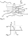
- the force sensor 5 can be arranged between the test element 6 and the compensation element 7, as in figure 5 shown.
- the compensating element 7 is in figure 5
- the force sensor 5 is elastically movable here against the test axis Z along the at least one spatial axis X due to the flexibility of the compensating element 7 in at least one axis.
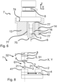
- the force sensor 5 can be arranged on the side of the compensating element 7 opposite the test element 6, as in the embodiment of the device 1 in 1 as in 6 shown schematically.
- the compensating element 7 is in 6 Shown as a sectional view for better understanding.
- the force sensor 5 is arranged immovably in a spatial direction X, Y perpendicular to the test axis Z.
- the force sensor 5 can also be arranged at a different position relative to the test part receptacle 3 . It is important that the force sensor is arranged in the force path in which the insertion force 52 or extraction force 54 can be measured.
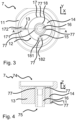
- the compensating element 7 has as in 3 and 4 shown an outer region 11 with a first surface 74.
- the compensating element 7 has an inner area 12 with a second surface 75 .
- the first surface 74 is configured to be connected to a body 32 .
- the second surface 75 is set up to be connected to a test element receptacle 3, as shown in FIG figure 5 shown.
- the inner area 12 is connected to the outer area 11 via at least one spring element 13 .
- the first surface 74 is arranged in the outer area 11 .
- the inner area 12 is reversibly movable relative to the outer area 11 . Due to the mobility of the inner area 12 relative to the outer area 11, the compensating element 7 is designed to be elastic.
- the first surface 74 can also be conical or hemispherical or the like.
- the inner area 12 has a first inner area 14 .
- the compensating element 7 has a second inner area 16 .
- the first inner area 14 is connected to the second inner area 16 via at least one spring element 15 .
- the first interior portion 14 is movable toward the second interior portion 16 .
- This division of the compensating element 7 into the outer area 11, first inner area 14 and second inner area 16 is advantageous because the spring element 15 between the first inner area 14 and second inner area 16 can be implemented independently of the spring element 13 between the outer area 11 and the first inner area 14 .
- Each spring element 13, 15 can have other properties in terms of spring force and/or preferred spring axis as the direction of movement.
- the spring axis is the axis in which the spring element 13,15 is designed to be elastically movable. Areas connected by a spring element 13, 15 are mainly movable along the spring axis. In some embodiments of a spring element 13, 15, the spring axis can have an arc shape.
- the spring element 13,15 is preferably designed in the form of a web.
- the web-shaped spring element 13,15 extends at least partially between the first surface 74 and the second surface 75.
- the compensating element 7 accordingly has a spring constant 71 in the direction of the test axis Z, which is at least twenty times higher than the spring constant 72,73 of the compensating element 7 in a direction perpendicular to the test axis Z.
- the web-shaped spring element 13,15 is elastic in the direction perpendicular to the test axis Z and the inner area 12 is elastically movable relative to the outer area 11 perpendicular to the test axis Z, while the spring constant 71 is rigid in comparison in the direction of the test axis Z and the inner area 12 is not or only slightly elastically movable relative to the outer area 11 .
- Slightly elastically movable means that the compensating element 7 has a spring constant 71 that is at least twenty times higher in the direction of the test axis Z than in a direction perpendicular to the test axis Z.
- the compensating element 7 shows through the spring element 13,15 has a spring constant 72,73 along the direction perpendicular to the test axis Z, along which the spring element 13,15 is elastically movable. in the in 3 embodiment shown, the spring axis is slightly arcuate. However, since the deflections of the spring element 13, 15 are small, the term spring axis or spatial axis will continue to be used below when the deflection of a spring element 13, 15 is described. This is advantageous because in the direction of the test axis Z it is not necessary to compensate for the offset of the plug-in element 2 relative to the test element 6 . It is even advantageous if the compensating element 7 is designed to be as rigid as possible in the direction of the test axis Z.
- the compensating element 7 would first be stretched or compressed, which would necessitate an unnecessary additional distance 9 when the test part 4 moves relative to the test part 3 . This would make the evaluation or assessment of the measurement more difficult.
- a test element 6 can be selected from plug-in elements that have already been produced, which plug-in element 2 has a plug-in force 52 with a further plug-in element 2 that has already been produced, which corresponds to a target plug-in force 521 and/or has a pull-out force 54 that corresponds to target pull-out force 541.
- a test element 6 can also be specially produced and, with a further plug-in element 2 specially produced for this purpose, have a plug-in force 52 which corresponds to the target plug-in force 521 and/or have a pull-out force 54 which corresponds to the target pull-out force 541.
- a test element 6 can also be produced specifically for this purpose and, with a further plug-in element 2 that has already been produced, have a plug-in force 52 which corresponds to the target plug-in force 521 and/or a pull-out force have, which corresponds to the target pull-out force 541 .
- the test element 6 can correspond to predetermined dimensions and have a defined coefficient of friction.
- the compensating element 7 is elastically movable in a first spatial axis X.
- the first spatial axis X is aligned largely perpendicularly to the test axis Z.
- the compensating element 7 is also elastically movable in a second spatial axis Y.
- the second spatial axis Y is oriented largely perpendicular to the test axis Z.
- First spatial axis X and second spatial axis Y are not parallel.
- the first spatial axis X and the second spatial axis Y advantageously form a two-dimensional, linearly independent coordinate system.
- first inner portion 14 is movable relative to the outer portion 11 along the first axis X perpendicular to the test axis Z and the first inner portion 14 is movable relative to the second inner portion 16 along the second axis Y perpendicular to the test axis Z and not parallel to the first axis X is movable.
- Outer area 11 and second inner area 16 can be moved relative to one another in this two-dimensional coordinate system. This means that an offset of the plug-in element 2 relative to the test element 6, which is connected to the second inner area 16, is compensated for by the compensating element 7.
- an angle between the first spatial axis X and the second spatial axis Y is an angle between 45° and 135°.
- An angle between the first spatial axis X and the second spatial axis Y is particularly preferably an angle of 90°.
- the spring force that is required is to move the second inner area 16 against the outer area 11 against the spring elements 13, 15 minimally compared to a non-orthogonal arrangement of the first spatial axis X and the second spatial axis Y.
- the compensating element 7 is preferably arranged between the test element receptacle 3 and a body 32 .
- the compensating element 7 has a spring constant 71 in the direction of the test axis.
- the compensating element 7 has a high spring constant 71 in the direction of the test axis Z.
- the compensating element 7 has an outer area, a first inner area 14 and a second inner area 16, with the first inner area 14 being movable relative to the outer area 11 in a first axis and the second inner area 16 being movable relative to the first inner area 14 along a second axis Y, a high spring constant is also given when the compensating element 7 has a spring constant of 72 in the direction of the first spatial axis X, and when the compensating element 7 has a spring constant of 73 in the direction of the second spatial axis Y and the spring constant is 72 of the first spatial axis X is at least a factor of twenty smaller than the spring constant 71 in the direction of the test axis Z and the spring constant 73 of the second axis Y is at least a factor of twenty smaller than the spring constant 71 in the direction of the test axis Z.
- a high spring constant 71 in The direction of the test axis Z is advantageous because when plugging in the plug connection, the equalization selement 7 is not excessively stretched
- Compensating element 7 is advantageously made of a metal or a metal alloy.
- the compensating element 7 is mechanically stressed by compensating for offsets during each measurement. Therefore, metals or metal alloys are suitable as a material for a compensating element because they are robust and durable.
- Aluminum is particularly preferred as the material for the compensating element 7 because it is easy to process.
- Spring elements 13, 15, for example in the form of webs can be easily produced from aluminum and are robust to mechanical stress, in particular alternating loads when the web is bent to move the inner area 12 towards the outer area 11 of the compensating element 7.
- other metals or metal alloys such as steels or stainless steels are also possible as the material for the compensating element 7 . From the material properties, the spring force along the test axis Z can easily be adjusted for different plug-in elements 2 with different plug-in forces 52 .
- the compensating element 7 is made of plastic. This has the advantage that the compensating element 7 can be produced quickly and inexpensively as an injection molded part.
- the plug-in element receptacle 4 accommodates at least two plug-in elements 2 .
- the device 1 then has a readying mechanism 42 for moving the plug-in element receptacle 4 in at least one axis perpendicular to the test axis.
- the provision mechanism 42 is set up to provide each of the at least two plug-in elements 2 at a position 21 on the test axis. In this way, several plug-in elements 2 can be placed in the plug-in element receptacle at the same time 4 and the pull-out force and/or plug-in force 52 are determined one after the other for each plug-in element 2 . This saves time since the device 1 does not have to be reloaded for each measurement of a plug-in element 2 .
- a supply mechanism 42 can be a motorized linear guide, a conveyor belt, a motorized two-axis translation table or a motorized compound table.
- the supply mechanism 42 for moving the plug-in element receptacle 4 can also be designed as a rotary table, with each of the at least two plug-in elements 2 being movable in a circular path R perpendicular to the test axis Z and the supply mechanism 42 being set up for each of the at least two plug-in elements 2 at a position 21 on the Provide test axis Z.
- a staging mechanism 42 is in 8 shown schematically.
- the test element receptacle 3 accommodates at least two test elements 6 in an interchangeable magazine.
- the interchangeable magazine is set up to provide each of the at least two test elements 6 at a position 61 on the test axis. This is advantageous because the set-up time is shortened if a different design of test element 6 is required for a corresponding design of plug-in elements.
- test element holder 3 and test element 6 can be made in one piece.
- the exchangeable magazine previously described is not possible.
- the device 1 preferably has an adjustment mechanism 8 .
- the test part holder 3 is with the adjustment mechanism 8 directly or indirectly fixed or reversibly detachably connected.
- the adjustment mechanism 8 is set up to move the test part receptacle 3 along the test axis Z, with the distance 9 between the plug-in part receptacle 4 and the test part receptacle 3 being able to be increased or decreased.
- An adjustment mechanism 8 is, for example, a motorized linear guide.
- An example of an adjustment mechanism 8 is the Type 2157B joining module from Kistler.
- An adjustment mechanism 8 has the advantage that the joining and/or detaching of the test element 6 and the plug-in element 2 can be carried out reproducibly in terms of speed and direction along the test axis Z.
- the speed should not usually exceed 300 mm/s for testing a plug-in element 2 .
- the impact of plug-in element 2 on test element 6 can lead to unwanted vibrations in force sensor 5, which falsify the measurement. Frictional forces have a speed-dependent component. Therefore, a predetermined speed should always be used to compare the measurements. Due to high speeds above 300°mm/s, test and specimens are heated excessively, which can also lead to incorrect measurements.
- the adjustment mechanism 8 is set up to determine a distance 9 of the movement along the test axis and to provide it as a distance signal 91 . This is advantageous since the insertion force 52 and/or extraction force 54 can be determined as a function of the distance 9.
- the distance 9 of the plug-in process can be determined until the plug-in connection is complete and can be compared between different plug-in elements 2 .
- An incorrect length of a plug-in element 2 can be identified in this way, even if the plug-in element 2 has a plug-in force of 52 and/or pullout force 54 should be within the insertion force tolerance or pullout force tolerance.
- the body 32 advantageously has the adjustment mechanism 8 .
- Material can be removed, for example, by machining or by wire EDM.
- the compensating element 7 can be manufactured in a simple, cost-effective and quick manner.
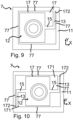
- Embodiments of a compensating element are in Figures 3 to 6 as well as 9 and 10 shown schematically.
- the compensating element 7 has at least one stop 77 .
- a stop 77 limits the movement of a spring element 13,15 in a direction perpendicular to the test axis Z. This is advantageous since a spring element 13,15 only has a specific deflection, a spring force which is linear to the deflection.
- the compensating element 7 has at least one stop 77 .
- the stop 77 also prevents excessive bending of the spring element 13,15. Excessive bending is present when the spring element 13,15 exhibits an irreversible deformation of the spring element 13,15 after such a bending.
- a stop 77 is, for example, a surface against which the spring element 13, 15 abuts at a specific deflection.
- the compensating element advantageously has at least one stop 77 for each spring element 13 , 15 .
- the compensating element particularly preferably has two stops 77 for each spring element 13, 15, which stops limit the movement of the spring element in both directions along the respective spatial axis X, Y.
- the compensating element has an inner area 12 and an outer area 11 .
- the inner area 12 is elastically connected to the outer area by two spring elements 13,15.
- a first spring element 13 is designed to be elastic along a first X axis.
- a second spring element 15 is designed to be elastic along a second Y axis.
- the spring elements 13,15 are preferably designed in the form of webs.
- the compensating element has an inner area 12 and an outer area 11 .
- the inner area 12 is elastically connected to the outer area by two spring elements 13, 15 which are directly connected to one another.
- a first spring element 13 is designed to be elastic along a first X axis.
- a second spring element 15 is designed to be elastic along a second Y axis.
- the inner area 12 is elastically connected to the outer area 11 with at least two further spring elements 13, 15, with a first spring element 13 being elastic along the first axis X and a second spring element 15 being elastic along the second axis Y.
- This embodiment of Compensating element 7 is more stable compared to the embodiment 9 .
- two connections of the outer area 11 and the inner area 12, each with two spring elements 13, 15, are preferred. Of course, more than two such connections are also conceivable.
- the force sensor 5 is a multi-component force sensor which, in addition to the insertion force along the test axis Z, also determines at least one transverse force along a first spatial axis X or a second spatial axis Y and/or at least one torque.
- the lateral force and/or the torque are provided as an additional force signal (not shown).
- the additional force signal can be used as a quality feature or included in the calculation of the insertion force or used to protect the measuring device.
- the plug-in element 2 is sorted out as defective.
- step j) If the pull-out force 54 in step j) does not match the target pull-out force 541 within a target pull-out force tolerance, then the plug-in element 2 is sorted out as defective.
- step j1 If the holding force 53 in optional step j1) does not match the setpoint holding force 531 within a setpoint holding force tolerance, then the plug-in element 2 is sorted out as faulty.
- a locking force S is predetermined, as in 7 shown. If the blocking force S is reached by the force signal 51, any movement of the device 1 is stopped. This ensures that the test element 6 is joined into the plug-in element 2 in accordance with the regulations. If the test element 6 is inserted too far into the plug-in element 2, there is a natural stop that should not be reached, since the plug-in element 2 and/or the test element 6 could be damaged. This is known as "running on block” in the case of a pin and socket as a probe and plug. Damage to the compensating element 7 due to excessive forces above the blocking force S is thus avoided.
- the invention can also be used for the automated assembly of pins in pin holes.
Applications Claiming Priority (1)
| Application Number | Priority Date | Filing Date | Title |
|---|---|---|---|
| EP21197789 | 2021-09-20 |
Publications (1)
| Publication Number | Publication Date |
|---|---|
| EP4151973A1 true EP4151973A1 (fr) | 2023-03-22 |
Family
ID=77864408
Family Applications (1)
| Application Number | Title | Priority Date | Filing Date |
|---|---|---|---|
| EP22193660.2A Pending EP4151973A1 (fr) | 2021-09-20 | 2022-09-02 | Dispositif d'essai d'au moins un élément enfichable |
Country Status (4)
| Country | Link |
|---|---|
| US (1) | US20230087704A1 (fr) |
| EP (1) | EP4151973A1 (fr) |
| JP (1) | JP2023044725A (fr) |
| CN (1) | CN115839832A (fr) |
Citations (8)
| Publication number | Priority date | Publication date | Assignee | Title |
|---|---|---|---|---|
| EP0185413A1 (fr) * | 1984-12-18 | 1986-06-25 | Koninklijke Philips Electronics N.V. | Connecteur pour le raccordement de fibres optiques |
| EP0703646A2 (fr) | 1994-09-02 | 1996-03-27 | Brökelmann, Jaeger & Busse GmbH & Co | Procédé et dispositif pour câbler les bornes de raccordement de composants d'appareils électriques |
| EP1063063A1 (fr) * | 1999-06-26 | 2000-12-27 | Carl Zeiss | Procédé pour déterminer le poids d'un palpeur d'une machine de mesure de coordonnées |
| EP1231679A1 (fr) * | 2001-02-09 | 2002-08-14 | HARTING KGaA | Connecteur composé d'une pièce male et femelle |
| EP2075883A2 (fr) * | 2007-12-27 | 2009-07-01 | Robert Bosch Gmbh | Dispositif de contrôle pour une connexion enfichable |
| DE102016213536A1 (de) * | 2016-07-25 | 2018-01-25 | Bayerische Motoren Werke Aktiengesellschaft | Verfahren zur Überwachung der Montage von Steckverbindungen |
| DE102018128622A1 (de) * | 2018-11-15 | 2020-05-20 | Bayerische Motoren Werke Aktiengesellschaft | Verfahren und Vorrichtung zur Überprüfung von Steckverbindungen |
| EP3757536A1 (fr) * | 2019-06-25 | 2020-12-30 | Kistler Holding AG | Dispositif de mesure de la force de contact et procédé de mesure d'une force de contact à l'aide d'un tel dispositif de mesure de la force de contact |
-
2022
- 2022-09-02 EP EP22193660.2A patent/EP4151973A1/fr active Pending
- 2022-09-16 JP JP2022147509A patent/JP2023044725A/ja active Pending
- 2022-09-19 US US17/947,439 patent/US20230087704A1/en active Pending
- 2022-09-20 CN CN202211141511.6A patent/CN115839832A/zh active Pending
Patent Citations (8)
| Publication number | Priority date | Publication date | Assignee | Title |
|---|---|---|---|---|
| EP0185413A1 (fr) * | 1984-12-18 | 1986-06-25 | Koninklijke Philips Electronics N.V. | Connecteur pour le raccordement de fibres optiques |
| EP0703646A2 (fr) | 1994-09-02 | 1996-03-27 | Brökelmann, Jaeger & Busse GmbH & Co | Procédé et dispositif pour câbler les bornes de raccordement de composants d'appareils électriques |
| EP1063063A1 (fr) * | 1999-06-26 | 2000-12-27 | Carl Zeiss | Procédé pour déterminer le poids d'un palpeur d'une machine de mesure de coordonnées |
| EP1231679A1 (fr) * | 2001-02-09 | 2002-08-14 | HARTING KGaA | Connecteur composé d'une pièce male et femelle |
| EP2075883A2 (fr) * | 2007-12-27 | 2009-07-01 | Robert Bosch Gmbh | Dispositif de contrôle pour une connexion enfichable |
| DE102016213536A1 (de) * | 2016-07-25 | 2018-01-25 | Bayerische Motoren Werke Aktiengesellschaft | Verfahren zur Überwachung der Montage von Steckverbindungen |
| DE102018128622A1 (de) * | 2018-11-15 | 2020-05-20 | Bayerische Motoren Werke Aktiengesellschaft | Verfahren und Vorrichtung zur Überprüfung von Steckverbindungen |
| EP3757536A1 (fr) * | 2019-06-25 | 2020-12-30 | Kistler Holding AG | Dispositif de mesure de la force de contact et procédé de mesure d'une force de contact à l'aide d'un tel dispositif de mesure de la force de contact |
Also Published As
| Publication number | Publication date |
|---|---|
| US20230087704A1 (en) | 2023-03-23 |
| JP2023044725A (ja) | 2023-03-31 |
| CN115839832A (zh) | 2023-03-24 |
Similar Documents
| Publication | Publication Date | Title |
|---|---|---|
| EP2328724B1 (fr) | Outil d'étalonnage, système et procédé d'étalonnage et d'alignement automatiques d'un dispositif de manipulation | |
| CH698426B1 (de) | Halterung für einen Drucksensor sowie Messrolle mit einem Drucksensor. | |
| WO2019170353A1 (fr) | Dispositif servant à vérifier une résistance de contact d'une liaison électromécanique et dispositif de recharge pour un véhicule électrique | |
| WO2011157261A2 (fr) | Procédé de mesure dynamométrique optique à faibles vibrations, notamment à températures élevées | |
| EP1007928B1 (fr) | Procede et dispositif pour controler des assemblages visses | |
| DE102011003652A1 (de) | Vorrichtung zur Messung eines Werkstückes und Verfahren zur Messung | |
| EP4151973A1 (fr) | Dispositif d'essai d'au moins un élément enfichable | |
| DE19581268B4 (de) | Dehnungsmesser | |
| DE102006026528A1 (de) | Vorrichtung und Verfahren zum Prüfen von mono- oder polykristallinen Siliziumscheiben | |
| DE69727964T2 (de) | Messapparat zur prüfung der linearen dimension von mechanischen teilen und zugehöriges herstellverfahren | |
| DE102009003231B4 (de) | Verfahren und Vorrichtung zur Überstandsmessung an Lagerschalen | |
| DE102016226282B4 (de) | Messelement, Messsystem und Verfahren zur Bereitstellung eines Messelements zur Messung von Kräften | |
| DE102014206373B4 (de) | Verfahren zur Bestimmung der Klemmkraft einer Nietverbindung | |
| DE102012015916A1 (de) | Prüfvorrichtung für ein Kugelgelenk und Verfahren zum Betreiben einer Prüfvorrichtung für ein Kugelgelenk | |
| EP1466157A1 (fr) | Dispositif de mesure de force a faible taux de vibrations dans des essais de traction dynamiques rapides sur des echantillons de materiaux | |
| EP2720021A2 (fr) | Dispositif de mesure de force | |
| DE102016011421B4 (de) | Anordnung und Verfahren zum Durchführen einer Biegeprüfung | |
| DE3511040C1 (de) | Haltevorrichtung fuer Schrauben beim Messen und Pruefen der Koaxialitaet von Gewinde und Schaft bzw. beim Bearbeiten | |
| DE102010016211B4 (de) | Verfahren zur Überwachung von Schraubverbindungen sowie Schrauben oder Schraubenbolzen zur Überwachung von Schraubverbindungen an Flanschverbindungen. | |
| WO2020147888A1 (fr) | Procédé et dispositif pour la surveillance de l'état d'éléments de pression d'un équipement de sertissage | |
| DE102006037904A1 (de) | Kontaktierungseinheit für elektronische Bauelemente | |
| EP1938665B1 (fr) | Dispositif et procede pour mesurer au moins un filetage conique | |
| DE102016225532B4 (de) | Vorrichtung und Verfahren zur Prüfung des Umformvermögens von Proben aus plastisch umformbaren Werkstoffen | |
| DE102020214958B4 (de) | Verfahren und Prüfvorrichtung zum Bestimmen einer Kontaktnormalkraft einer Kontaktfeder eines elektrischen Steckkontakts | |
| EP1556722B1 (fr) | Dispositif pour fixer l'extremite d'un cable dans un passage d'un connecteur |
Legal Events
| Date | Code | Title | Description |
|---|---|---|---|
| PUAI | Public reference made under article 153(3) epc to a published international application that has entered the european phase |
Free format text: ORIGINAL CODE: 0009012 |
|
| STAA | Information on the status of an ep patent application or granted ep patent |
Free format text: STATUS: THE APPLICATION HAS BEEN PUBLISHED |
|
| AK | Designated contracting states |
Kind code of ref document: A1 Designated state(s): AL AT BE BG CH CY CZ DE DK EE ES FI FR GB GR HR HU IE IS IT LI LT LU LV MC MK MT NL NO PL PT RO RS SE SI SK SM TR |
|
| STAA | Information on the status of an ep patent application or granted ep patent |
Free format text: STATUS: REQUEST FOR EXAMINATION WAS MADE |
|
| 17P | Request for examination filed |
Effective date: 20230828 |
|
| RBV | Designated contracting states (corrected) |
Designated state(s): AL AT BE BG CH CY CZ DE DK EE ES FI FR GB GR HR HU IE IS IT LI LT LU LV MC MK MT NL NO PL PT RO RS SE SI SK SM TR |