EP4151973A1 - Device for testing at least one plug-in element - Google Patents
Device for testing at least one plug-in element Download PDFInfo
- Publication number
- EP4151973A1 EP4151973A1 EP22193660.2A EP22193660A EP4151973A1 EP 4151973 A1 EP4151973 A1 EP 4151973A1 EP 22193660 A EP22193660 A EP 22193660A EP 4151973 A1 EP4151973 A1 EP 4151973A1
- Authority
- EP
- European Patent Office
- Prior art keywords
- plug
- test
- axis
- force
- compensating
- Prior art date
- Legal status (The legal status is an assumption and is not a legal conclusion. Google has not performed a legal analysis and makes no representation as to the accuracy of the status listed.)
- Pending
Links
Images

Classifications
-
- H—ELECTRICITY
- H01—ELECTRIC ELEMENTS
- H01R—ELECTRICALLY-CONDUCTIVE CONNECTIONS; STRUCTURAL ASSOCIATIONS OF A PLURALITY OF MUTUALLY-INSULATED ELECTRICAL CONNECTING ELEMENTS; COUPLING DEVICES; CURRENT COLLECTORS
- H01R43/00—Apparatus or processes specially adapted for manufacturing, assembling, maintaining, or repairing of line connectors or current collectors or for joining electric conductors
- H01R43/26—Apparatus or processes specially adapted for manufacturing, assembling, maintaining, or repairing of line connectors or current collectors or for joining electric conductors for engaging or disengaging the two parts of a coupling device
-
- G—PHYSICS
- G01—MEASURING; TESTING
- G01R—MEASURING ELECTRIC VARIABLES; MEASURING MAGNETIC VARIABLES
- G01R1/00—Details of instruments or arrangements of the types included in groups G01R5/00 - G01R13/00 and G01R31/00
- G01R1/02—General constructional details
- G01R1/04—Housings; Supporting members; Arrangements of terminals
- G01R1/0408—Test fixtures or contact fields; Connectors or connecting adaptors; Test clips; Test sockets
- G01R1/0416—Connectors, terminals
-
- G—PHYSICS
- G01—MEASURING; TESTING
- G01L—MEASURING FORCE, STRESS, TORQUE, WORK, MECHANICAL POWER, MECHANICAL EFFICIENCY, OR FLUID PRESSURE
- G01L5/00—Apparatus for, or methods of, measuring force, work, mechanical power, or torque, specially adapted for specific purposes
- G01L5/0028—Force sensors associated with force applying means
- G01L5/0033—Force sensors associated with force applying means applying a pulling force
-
- G—PHYSICS
- G01—MEASURING; TESTING
- G01L—MEASURING FORCE, STRESS, TORQUE, WORK, MECHANICAL POWER, MECHANICAL EFFICIENCY, OR FLUID PRESSURE
- G01L5/00—Apparatus for, or methods of, measuring force, work, mechanical power, or torque, specially adapted for specific purposes
- G01L5/0028—Force sensors associated with force applying means
- G01L5/0038—Force sensors associated with force applying means applying a pushing force
-
- G—PHYSICS
- G01—MEASURING; TESTING
- G01L—MEASURING FORCE, STRESS, TORQUE, WORK, MECHANICAL POWER, MECHANICAL EFFICIENCY, OR FLUID PRESSURE
- G01L5/00—Apparatus for, or methods of, measuring force, work, mechanical power, or torque, specially adapted for specific purposes
- G01L5/0057—Apparatus for, or methods of, measuring force, work, mechanical power, or torque, specially adapted for specific purposes measuring forces due to spring-shaped elements
-
- G—PHYSICS
- G01—MEASURING; TESTING
- G01L—MEASURING FORCE, STRESS, TORQUE, WORK, MECHANICAL POWER, MECHANICAL EFFICIENCY, OR FLUID PRESSURE
- G01L5/00—Apparatus for, or methods of, measuring force, work, mechanical power, or torque, specially adapted for specific purposes
- G01L5/0061—Force sensors associated with industrial machines or actuators
- G01L5/0076—Force sensors associated with manufacturing machines
- G01L5/009—Force sensors associated with material gripping devices
-
- G—PHYSICS
- G01—MEASURING; TESTING
- G01M—TESTING STATIC OR DYNAMIC BALANCE OF MACHINES OR STRUCTURES; TESTING OF STRUCTURES OR APPARATUS, NOT OTHERWISE PROVIDED FOR
- G01M5/00—Investigating the elasticity of structures, e.g. deflection of bridges or air-craft wings
- G01M5/0041—Investigating the elasticity of structures, e.g. deflection of bridges or air-craft wings by determining deflection or stress
- G01M5/005—Investigating the elasticity of structures, e.g. deflection of bridges or air-craft wings by determining deflection or stress by means of external apparatus, e.g. test benches or portable test systems
-
- G—PHYSICS
- G01—MEASURING; TESTING
- G01R—MEASURING ELECTRIC VARIABLES; MEASURING MAGNETIC VARIABLES
- G01R31/00—Arrangements for testing electric properties; Arrangements for locating electric faults; Arrangements for electrical testing characterised by what is being tested not provided for elsewhere
- G01R31/50—Testing of electric apparatus, lines, cables or components for short-circuits, continuity, leakage current or incorrect line connections
- G01R31/66—Testing of connections, e.g. of plugs or non-disconnectable joints
-
- G—PHYSICS
- G02—OPTICS
- G02B—OPTICAL ELEMENTS, SYSTEMS OR APPARATUS
- G02B6/00—Light guides; Structural details of arrangements comprising light guides and other optical elements, e.g. couplings
- G02B6/24—Coupling light guides
- G02B6/36—Mechanical coupling means
- G02B6/38—Mechanical coupling means having fibre to fibre mating means
- G02B6/3807—Dismountable connectors, i.e. comprising plugs
- G02B6/3833—Details of mounting fibres in ferrules; Assembly methods; Manufacture
- G02B6/385—Accessories for testing or observation of connectors
Definitions
- the invention relates to a device for testing at least one plug-in element of a plug-in connection.
- the invention also relates to a method for testing plug-in elements of a plug-in connection.
- the invention further relates to the use of a compensation element according to the invention in a device for testing plug-in elements of a plug-in connection.
- the invention also relates to the production of a compensation element according to the invention for use in a device for testing plug-in elements of a plug-in connection.
- Connectors are used in a variety of applications.
- plug-in connections in the electrical industry are known as electrical plug-in connections in order to connect electrically conductive elements to one another and to establish electrical contact.
- plug-in connections are also known in other areas, for example in pipeline construction, in which two pipes are connected to one another by plugging them together and realizing a continuous pipeline.
- Plug-in elements are also known in the optical industry, for example for connecting optical lines.
- Optical lines are, for example, so-called glass fibers.
- plug-in connections In the electrical industry, connections between two plug-in elements, so-called plug-in connections, are often designed to be reversible, with a plug-in connection consisting of two plug-in elements is executed.
- a first plug-in element is connected to a further plug-in element by bringing them together. This process is also commonly referred to as plugging or plugging in.
- plug-in element is understood below to mean that a plug-in element produces a plug-in connection with a corresponding further plug-in element by bringing the plug-in element and further plug-in element together.
- the merging is generally a linear movement.
- the plug-in element is suitably aligned to produce a plug-in connection with the other plug-in element and is then brought together with a precise fit.
- the plug connection is often non-positively releasably fixed. This is done, for example, by a spring force which the plug-in element exerts on the other plug-in element.
- the additional plug-in element can exert a spring force on the plug-in element.
- a force must therefore be applied with which the plug-in element is pressed into the other plug-in element. This force is called the insertion force.
- the insertion force and extraction force vary depending on the application.
- low pull-out forces of a few 100 mN are known.
- Pull-out forces of several 100 N are also known for mechanically highly stressed plug connections. Pull-out forces are also known as part of DIN EN 60512-1-100_2012.
- the insertion force and extraction force for a plug connection do not deviate by more than an insertion force tolerance or extraction force tolerance from a nominal insertion force value or nominal extraction force value.
- the insertion force and/or extraction force for connectors must be checked.
- a plug-in element is inserted into another plug-in element and the force that occurs to join the plug-in connection is determined.
- the force determined in this connector test must be within a predetermined range specified for a high quality connector.
- a conductor insertion end is inserted as a test element by means of a gripper into a connection point as a plug-in element.
- the gripper is a test element holder.
- the test element holder is mounted on a force transducer, which determines the insertion force when joining the plug connection.
- a force acting opposite to the insertion force is applied up to a target value of a conductor holding force, holding force for short, which is below the pull-out force target value. If the plug connection does not come loose, corresponds the connector meets the requirements.
- the insertion force and/or extraction force between the plug-in element and the test element is checked.
- the term plug-in element is used for the plug-in element to be tested.
- a plug-in element or test element can be female or male, with the corresponding further plug-in element of the plug-in connection being male or female accordingly.
- a plug-in element can also be genderless, with the other plug-in element of the plug-in connection also being correspondingly genderless.
- the male plug element of a plug connection generally has contact pins pointing outwards.
- a contact pin is often also referred to as a pin.
- the female tab generally has inwardly facing contact openings.
- the male connector is also commonly known as a plug or chassis connector.
- the female plug is also commonly known as a socket or coupler.
- Insertion force and extraction force are each defined in a test axis along which the plug connection is inserted or removed.
- the plug-in element and the test element are arranged on the test axis. If the test element or plug-in element is offset from the test axis, the plug-in force is not correctly determined.
- joining or loosening a plug connection is also referred to as plugging a plug connection.
- the pull-out force and/or plug-in force of the manufactured plug-in element is checked at least randomly with a suitable test element.
- the inspection element has predetermined dimensions and properties. In this way, wear and tear on the production machine and/or tool or an incorrect setting of the machine can be detected and a reject of manufactured plug-in elements which are not within the plug-in force tolerance or plug-out force tolerance of the plug-in force setpoint or plug-out force setpoint can be avoided.
- the plug-in element is loaded asymmetrically, the plug-in force or pull-out force cannot be determined correctly. If there is an offset between the plug-in element and the test element perpendicular to the test axis, a lateral force, as already mentioned, occurs when the plug-in connection is plugged in. This results in excessive bending on one side of the tab while the other side of the tab is correspondingly less stressed. This leads to changed friction and a resulting changed effort when plugging in the connector.
- a tilting against the test axis of at least one of the connecting element and counter-element can also not be a precise fit. Due to the angular error, axial forces also occur in addition to the transverse forces, which also falsify the measurement.
- the object of the invention is to improve the influence of disruptive forces on the determination of the insertion force and/or extraction force.
- a further object of the invention is to compensate for an offset between the test element and the plug-in element.
- the invention relates to a device for testing at least one plug-in element; with a test element, which can be plugged into the plug-in element for testing; with a plug-in element receptacle in which a plug-in element is arranged; with a test element holder in which the test element is arranged; wherein the plug element receptacle and the test element receptacle are movably arranged along a test axis for plugging; with a force sensor, which is set up to determine a force when plugging in along the test axis and to provide it as a force signal; characterized in that the device has a compensating element for compensating for an offset between the plug-in element and the test element; that the compensating element is designed to be at least partially elastic in at least one spatial axis; that the test element receptacle is arranged in operative connection with the compensating element in such a way that the test element can be moved elastically along the spatial axis.
- a plug-in element is tested with a test element.
- the plug-in element is arranged in the plug-in element receptacle and fixed with a fixing element.
- the fixing element can be a spring which fixes the plug-in element in the plug-in element receptacle by means of a force fit.
- the fixing element can also be a screw, which fixes the plug-in element in the plug-in element receptacle in a non-positive manner.
- a test element is fixed in the test element receptacle, which test element is suitable for forming a plug-in connection with the plug-in element.
- the test element is in the form of a pin when the plug-in element is in the form of a socket.
- a plug-in connection is plugged in between the plug-in element and the test element along the test axis.
- the test element is arranged in the test element receptacle and the plug-in element is arranged in the plug-in element receptacle in such a way that plug-in element and Test element are arranged coaxially and are also aligned coaxially to the test axis along which test element receptacle and plug element receptacle are movable.
- a plug-in force can be determined without any disruptive influences, since the plug-in element and test element are aligned in the best possible way. In practice, however, there is always an offset or tilting between the plug-in element and the test element.
- This offset influences the determination of the insertion force and/or extraction force in such a way that the minimum insertion force and/or extraction force is not determined.
- a comparison between the insertion force and extraction force of different plug-in elements is not possible, since the plug-in force depends on the offset, which changes each time a plug-in element is fixed in the plug-in element receptacle.
- the compensating element compensates for the offset or tilting. The compensation takes place in that the compensation element is designed to be flexible. If the plug-in element and the test element are offset from one another when they are plugged in, they align themselves coaxially when they make contact, since the transverse force that occurs when they are tilted or offset correspondingly elastically deforms the compensating element. However, the offset may only be so great that the plug-in element and test element can still be joined. An offset of more than half the diameter of the plug-in element or the test element cannot be compensated for without additional measures.
- a period of time between the completed manufacture of the plug-in element and the testing of the plug-in element is only a few seconds to hours. If several plug contacts do not meet the requirements, there may be a problem in production, for example incorrect dimensions of the plug contact or an incorrect one material choice. In order to solve the problem quickly during production and to avoid faulty plug contacts, the shortest possible time span between a few seconds and minutes is particularly advantageous.
- a signal in particular a force signal, is a time sequence of force values.
- An increase in a force signal is given when the force value changes from a value of zero to a finite value. a finite one The value is different from zero or the zero point if it exceeds the noise of the force signal. Due to the inertial mass of the test element, a movement of the test element can exert a force on the force sensor and thus generate a force signal which is close to zero. This is not understood as an increase in the force signal.
- there is a drop in a force signal when the force value changes from a finite value to a value of zero.
- plug-in element is sorted out as defective.
- a rejected plug-in element is also referred to as scrap. If the scrap exceeds a value set in advance, the production system is checked and adjusted if necessary. With the method, problems in the production of plug-in elements can be identified quickly and at an early stage.
- the method can be used to inspect all of the manufactured plugs, or a subset of all of the manufactured plugs can be inspected.
- the electrical conductance between the test element and the plug-in element is continuously determined and made available by a conductance measuring device as a function of the distance.
- This additional information on the conductance makes it possible to determine the distance at which the plug-in element and test element are in contact.
- it can advantageously be determined whether the conductance is within a conductance tolerance. Is the guiding value not within the conductance tolerance, this may indicate a problem in the manufacture of the plug contact. This can be, for example and not in an exhaustive list, contamination of the plug-in element, insufficient cleaning of the plug-in element, corrosion of the plug-in element.
- An insufficient insertion force can also be the cause of an insufficient conductance and can be recognized directly from the force signal.
- the 1 shows a device 1 for testing at least one plug-in element 2.
- the device 1 has a plug-in element receptacle 4 for at least one plug-in element 2.
- the device 1 has at least one test element receptacle 3 for at least one test element 6 .
- the test element receptacle 3 and the plug element receptacle 4 are arranged along a test axis Z.
- the test element receptacle 3 and the plug element receptacle 4 can be moved relative to one another along the test axis Z.
- test element receptacle 3 and plug element receptacle 4 are possible along the test axis toward or away from one another, so that a distance 9 between test element receptacle 3 and plug element receptacle 4 increases or decreases.
- test element receptacle 3 movements between the test element receptacle 3 and the plug element receptacle 4 are also conceivable, which can also be curved or shaped in some other way, at least for short plug-in distances.
- a plug-in element receptacle 4 receives a plug-in element 2 to be tested and fixes the plug-in element 2 in the plug-in element receptacle 4. After the test has been completed, the plug-in element 2 can be removed again.
- the fixation is therefore designed to be reversible.
- the fixation can be non-positive, for example by a fastening element or a clamping element.
- a fastener such as a bolt or nut.
- a clamping element is, for example, a spring or a rubber.
- the fixation can also take place in a form-fitting manner.
- a form-fitting fixation can be a cotter pin, which engages in a corresponding recess. In one embodiment, the fixation fixes the plug-in element 2 and withstands a force greater than 1.5 times the target pull-out force.
- a test element receptacle 3 accommodates the test element 6 and fixes the test element 6 in the test element receptacle 3. After a plug-in element 2 has been tested with the test element 6, the test element 6 remains in the test element receptacle in order to be able to test a next plug-in element 2.
- the fixation of the test element 6 is designed to be reversible. The test element 6 can thus be exchanged if necessary, for example if a different type of plug-in element is to be tested.
- the fixing of the test element 6 can be carried out in a force-fitting manner, for example by means of a fastening element or a clamping element.
- a fastener such as a bolt or nut.
- a clamping element is for example a spring or a rubber.
- the test element 6 can also be fixed in a form-fitting manner.
- a form-fitting fixation can be a cotter pin, which engages in a corresponding recess.
- the fixation fixes the test element 6 and withstands a force greater than 1.5 times the target pull-out force.
- the device 1 has a force sensor 5 which is set up to determine a force 50 during insertion along the test axis Z and to provide it as a force signal 51 .
- This is, for example, a force sensor 5, which determines a force at least along one axis.
- Force sensors 5 can determine a force via a geometric change in at least one strain gauge.
- a possible force sensor 5 based on strain gauges is available in the Kistler Type 4576A series.
- An example of a piezoelectric force sensor 5 is the Kistler type 9001C or type 9217A.
- a pull-out force 54 is determined as a pulling force.
- An insertion force 52 is determined as a compressive force.
- the force sensor 5 is set up to determine a force along the test axis Z and to provide it as a force signal 51 .
- the force signal 51 has the insertion force 52 during the assembly of the plug-in connection made up of the plug-in element 2 and the test element 6 .
- the force signal 51 indicates during release the plug-in connection from plug-in element 2 and test element 6 to the pull-out force. It is advantageous to determine the force exclusively along the test axis. Although there are force sensors that can also determine forces in more than one axis, these are more expensive than comparably sensitive force sensors that only determine the force in one axis.
- a force signal is shown schematically in 7 shown.
- the device 1 has a compensating element 7 for compensating for an offset between the plug-in element 2 and the test element 6 .
- the compensating element 7 is designed to be at least partially elastic in at least one spatial axis X.
- the test element receptacle 3 is arranged in an operative connection with the compensating element 7 in such a way that the test element 6 can be moved elastically along the at least one spatial axis X.
- the test element 6 and the plug-in element 2 are fixed in such a way that the test element 6 and the plug-in element 2 are largely arranged on the Z test axis.
- test axis Z is to be understood in such a way that the joining of a plug connection between the test element 6 and the plug element 2 is possible with a movement of the test element receptacle 3 and the plug element receptacle 4 along the test axis.
- the test element 6 is suitable for forming a plug-in connection 23 with the plug-in element 2 .
- An offset of plug-in element 2 and test element 6 relative to one another influences the determination of plug-in force 52 and/or pull-out force 54 in such a way that minimum plug-in force 52 and/or pull-out force 54 is not determined.
- the minimum insertion force 52 and/or extraction force 54 is the relevant variable to be determined.
- the compensating element 7 compensates for the offset or tilting in at least one axis if the axis is not parallel to the test axis.
- the compensation takes place in that the compensation element 7 is flexible in at least one axis, which axis is not parallel to the test axis. If the plug-in element 2 and the test element 6 are offset or tilted relative to one another, they align themselves coaxially when plugged in, since the transverse force occurring when tilted or offset elastically deforms the compensating element 7 in at least one axis X,Y.
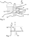
- the force sensor 5 can be arranged between the test element 6 and the compensation element 7, as in figure 5 shown.
- the compensating element 7 is in figure 5
- the force sensor 5 is elastically movable here against the test axis Z along the at least one spatial axis X due to the flexibility of the compensating element 7 in at least one axis.
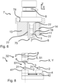
- the force sensor 5 can be arranged on the side of the compensating element 7 opposite the test element 6, as in the embodiment of the device 1 in 1 as in 6 shown schematically.
- the compensating element 7 is in 6 Shown as a sectional view for better understanding.
- the force sensor 5 is arranged immovably in a spatial direction X, Y perpendicular to the test axis Z.
- the force sensor 5 can also be arranged at a different position relative to the test part receptacle 3 . It is important that the force sensor is arranged in the force path in which the insertion force 52 or extraction force 54 can be measured.
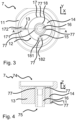
- the compensating element 7 has as in 3 and 4 shown an outer region 11 with a first surface 74.
- the compensating element 7 has an inner area 12 with a second surface 75 .
- the first surface 74 is configured to be connected to a body 32 .
- the second surface 75 is set up to be connected to a test element receptacle 3, as shown in FIG figure 5 shown.
- the inner area 12 is connected to the outer area 11 via at least one spring element 13 .
- the first surface 74 is arranged in the outer area 11 .
- the inner area 12 is reversibly movable relative to the outer area 11 . Due to the mobility of the inner area 12 relative to the outer area 11, the compensating element 7 is designed to be elastic.
- the first surface 74 can also be conical or hemispherical or the like.
- the inner area 12 has a first inner area 14 .
- the compensating element 7 has a second inner area 16 .
- the first inner area 14 is connected to the second inner area 16 via at least one spring element 15 .
- the first interior portion 14 is movable toward the second interior portion 16 .
- This division of the compensating element 7 into the outer area 11, first inner area 14 and second inner area 16 is advantageous because the spring element 15 between the first inner area 14 and second inner area 16 can be implemented independently of the spring element 13 between the outer area 11 and the first inner area 14 .
- Each spring element 13, 15 can have other properties in terms of spring force and/or preferred spring axis as the direction of movement.
- the spring axis is the axis in which the spring element 13,15 is designed to be elastically movable. Areas connected by a spring element 13, 15 are mainly movable along the spring axis. In some embodiments of a spring element 13, 15, the spring axis can have an arc shape.
- the spring element 13,15 is preferably designed in the form of a web.
- the web-shaped spring element 13,15 extends at least partially between the first surface 74 and the second surface 75.
- the compensating element 7 accordingly has a spring constant 71 in the direction of the test axis Z, which is at least twenty times higher than the spring constant 72,73 of the compensating element 7 in a direction perpendicular to the test axis Z.
- the web-shaped spring element 13,15 is elastic in the direction perpendicular to the test axis Z and the inner area 12 is elastically movable relative to the outer area 11 perpendicular to the test axis Z, while the spring constant 71 is rigid in comparison in the direction of the test axis Z and the inner area 12 is not or only slightly elastically movable relative to the outer area 11 .
- Slightly elastically movable means that the compensating element 7 has a spring constant 71 that is at least twenty times higher in the direction of the test axis Z than in a direction perpendicular to the test axis Z.
- the compensating element 7 shows through the spring element 13,15 has a spring constant 72,73 along the direction perpendicular to the test axis Z, along which the spring element 13,15 is elastically movable. in the in 3 embodiment shown, the spring axis is slightly arcuate. However, since the deflections of the spring element 13, 15 are small, the term spring axis or spatial axis will continue to be used below when the deflection of a spring element 13, 15 is described. This is advantageous because in the direction of the test axis Z it is not necessary to compensate for the offset of the plug-in element 2 relative to the test element 6 . It is even advantageous if the compensating element 7 is designed to be as rigid as possible in the direction of the test axis Z.
- the compensating element 7 would first be stretched or compressed, which would necessitate an unnecessary additional distance 9 when the test part 4 moves relative to the test part 3 . This would make the evaluation or assessment of the measurement more difficult.
- a test element 6 can be selected from plug-in elements that have already been produced, which plug-in element 2 has a plug-in force 52 with a further plug-in element 2 that has already been produced, which corresponds to a target plug-in force 521 and/or has a pull-out force 54 that corresponds to target pull-out force 541.
- a test element 6 can also be specially produced and, with a further plug-in element 2 specially produced for this purpose, have a plug-in force 52 which corresponds to the target plug-in force 521 and/or have a pull-out force 54 which corresponds to the target pull-out force 541.
- a test element 6 can also be produced specifically for this purpose and, with a further plug-in element 2 that has already been produced, have a plug-in force 52 which corresponds to the target plug-in force 521 and/or a pull-out force have, which corresponds to the target pull-out force 541 .
- the test element 6 can correspond to predetermined dimensions and have a defined coefficient of friction.
- the compensating element 7 is elastically movable in a first spatial axis X.
- the first spatial axis X is aligned largely perpendicularly to the test axis Z.
- the compensating element 7 is also elastically movable in a second spatial axis Y.
- the second spatial axis Y is oriented largely perpendicular to the test axis Z.
- First spatial axis X and second spatial axis Y are not parallel.
- the first spatial axis X and the second spatial axis Y advantageously form a two-dimensional, linearly independent coordinate system.
- first inner portion 14 is movable relative to the outer portion 11 along the first axis X perpendicular to the test axis Z and the first inner portion 14 is movable relative to the second inner portion 16 along the second axis Y perpendicular to the test axis Z and not parallel to the first axis X is movable.
- Outer area 11 and second inner area 16 can be moved relative to one another in this two-dimensional coordinate system. This means that an offset of the plug-in element 2 relative to the test element 6, which is connected to the second inner area 16, is compensated for by the compensating element 7.
- an angle between the first spatial axis X and the second spatial axis Y is an angle between 45° and 135°.
- An angle between the first spatial axis X and the second spatial axis Y is particularly preferably an angle of 90°.
- the spring force that is required is to move the second inner area 16 against the outer area 11 against the spring elements 13, 15 minimally compared to a non-orthogonal arrangement of the first spatial axis X and the second spatial axis Y.
- the compensating element 7 is preferably arranged between the test element receptacle 3 and a body 32 .
- the compensating element 7 has a spring constant 71 in the direction of the test axis.
- the compensating element 7 has a high spring constant 71 in the direction of the test axis Z.
- the compensating element 7 has an outer area, a first inner area 14 and a second inner area 16, with the first inner area 14 being movable relative to the outer area 11 in a first axis and the second inner area 16 being movable relative to the first inner area 14 along a second axis Y, a high spring constant is also given when the compensating element 7 has a spring constant of 72 in the direction of the first spatial axis X, and when the compensating element 7 has a spring constant of 73 in the direction of the second spatial axis Y and the spring constant is 72 of the first spatial axis X is at least a factor of twenty smaller than the spring constant 71 in the direction of the test axis Z and the spring constant 73 of the second axis Y is at least a factor of twenty smaller than the spring constant 71 in the direction of the test axis Z.
- a high spring constant 71 in The direction of the test axis Z is advantageous because when plugging in the plug connection, the equalization selement 7 is not excessively stretched
- Compensating element 7 is advantageously made of a metal or a metal alloy.
- the compensating element 7 is mechanically stressed by compensating for offsets during each measurement. Therefore, metals or metal alloys are suitable as a material for a compensating element because they are robust and durable.
- Aluminum is particularly preferred as the material for the compensating element 7 because it is easy to process.
- Spring elements 13, 15, for example in the form of webs can be easily produced from aluminum and are robust to mechanical stress, in particular alternating loads when the web is bent to move the inner area 12 towards the outer area 11 of the compensating element 7.
- other metals or metal alloys such as steels or stainless steels are also possible as the material for the compensating element 7 . From the material properties, the spring force along the test axis Z can easily be adjusted for different plug-in elements 2 with different plug-in forces 52 .
- the compensating element 7 is made of plastic. This has the advantage that the compensating element 7 can be produced quickly and inexpensively as an injection molded part.
- the plug-in element receptacle 4 accommodates at least two plug-in elements 2 .
- the device 1 then has a readying mechanism 42 for moving the plug-in element receptacle 4 in at least one axis perpendicular to the test axis.
- the provision mechanism 42 is set up to provide each of the at least two plug-in elements 2 at a position 21 on the test axis. In this way, several plug-in elements 2 can be placed in the plug-in element receptacle at the same time 4 and the pull-out force and/or plug-in force 52 are determined one after the other for each plug-in element 2 . This saves time since the device 1 does not have to be reloaded for each measurement of a plug-in element 2 .
- a supply mechanism 42 can be a motorized linear guide, a conveyor belt, a motorized two-axis translation table or a motorized compound table.
- the supply mechanism 42 for moving the plug-in element receptacle 4 can also be designed as a rotary table, with each of the at least two plug-in elements 2 being movable in a circular path R perpendicular to the test axis Z and the supply mechanism 42 being set up for each of the at least two plug-in elements 2 at a position 21 on the Provide test axis Z.
- a staging mechanism 42 is in 8 shown schematically.
- the test element receptacle 3 accommodates at least two test elements 6 in an interchangeable magazine.
- the interchangeable magazine is set up to provide each of the at least two test elements 6 at a position 61 on the test axis. This is advantageous because the set-up time is shortened if a different design of test element 6 is required for a corresponding design of plug-in elements.
- test element holder 3 and test element 6 can be made in one piece.
- the exchangeable magazine previously described is not possible.
- the device 1 preferably has an adjustment mechanism 8 .
- the test part holder 3 is with the adjustment mechanism 8 directly or indirectly fixed or reversibly detachably connected.
- the adjustment mechanism 8 is set up to move the test part receptacle 3 along the test axis Z, with the distance 9 between the plug-in part receptacle 4 and the test part receptacle 3 being able to be increased or decreased.
- An adjustment mechanism 8 is, for example, a motorized linear guide.
- An example of an adjustment mechanism 8 is the Type 2157B joining module from Kistler.
- An adjustment mechanism 8 has the advantage that the joining and/or detaching of the test element 6 and the plug-in element 2 can be carried out reproducibly in terms of speed and direction along the test axis Z.
- the speed should not usually exceed 300 mm/s for testing a plug-in element 2 .
- the impact of plug-in element 2 on test element 6 can lead to unwanted vibrations in force sensor 5, which falsify the measurement. Frictional forces have a speed-dependent component. Therefore, a predetermined speed should always be used to compare the measurements. Due to high speeds above 300°mm/s, test and specimens are heated excessively, which can also lead to incorrect measurements.
- the adjustment mechanism 8 is set up to determine a distance 9 of the movement along the test axis and to provide it as a distance signal 91 . This is advantageous since the insertion force 52 and/or extraction force 54 can be determined as a function of the distance 9.
- the distance 9 of the plug-in process can be determined until the plug-in connection is complete and can be compared between different plug-in elements 2 .
- An incorrect length of a plug-in element 2 can be identified in this way, even if the plug-in element 2 has a plug-in force of 52 and/or pullout force 54 should be within the insertion force tolerance or pullout force tolerance.
- the body 32 advantageously has the adjustment mechanism 8 .
- Material can be removed, for example, by machining or by wire EDM.
- the compensating element 7 can be manufactured in a simple, cost-effective and quick manner.
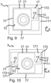
- Embodiments of a compensating element are in Figures 3 to 6 as well as 9 and 10 shown schematically.
- the compensating element 7 has at least one stop 77 .
- a stop 77 limits the movement of a spring element 13,15 in a direction perpendicular to the test axis Z. This is advantageous since a spring element 13,15 only has a specific deflection, a spring force which is linear to the deflection.
- the compensating element 7 has at least one stop 77 .
- the stop 77 also prevents excessive bending of the spring element 13,15. Excessive bending is present when the spring element 13,15 exhibits an irreversible deformation of the spring element 13,15 after such a bending.
- a stop 77 is, for example, a surface against which the spring element 13, 15 abuts at a specific deflection.
- the compensating element advantageously has at least one stop 77 for each spring element 13 , 15 .
- the compensating element particularly preferably has two stops 77 for each spring element 13, 15, which stops limit the movement of the spring element in both directions along the respective spatial axis X, Y.
- the compensating element has an inner area 12 and an outer area 11 .
- the inner area 12 is elastically connected to the outer area by two spring elements 13,15.
- a first spring element 13 is designed to be elastic along a first X axis.
- a second spring element 15 is designed to be elastic along a second Y axis.
- the spring elements 13,15 are preferably designed in the form of webs.
- the compensating element has an inner area 12 and an outer area 11 .
- the inner area 12 is elastically connected to the outer area by two spring elements 13, 15 which are directly connected to one another.
- a first spring element 13 is designed to be elastic along a first X axis.
- a second spring element 15 is designed to be elastic along a second Y axis.
- the inner area 12 is elastically connected to the outer area 11 with at least two further spring elements 13, 15, with a first spring element 13 being elastic along the first axis X and a second spring element 15 being elastic along the second axis Y.
- This embodiment of Compensating element 7 is more stable compared to the embodiment 9 .
- two connections of the outer area 11 and the inner area 12, each with two spring elements 13, 15, are preferred. Of course, more than two such connections are also conceivable.
- the force sensor 5 is a multi-component force sensor which, in addition to the insertion force along the test axis Z, also determines at least one transverse force along a first spatial axis X or a second spatial axis Y and/or at least one torque.
- the lateral force and/or the torque are provided as an additional force signal (not shown).
- the additional force signal can be used as a quality feature or included in the calculation of the insertion force or used to protect the measuring device.
- the plug-in element 2 is sorted out as defective.
- step j) If the pull-out force 54 in step j) does not match the target pull-out force 541 within a target pull-out force tolerance, then the plug-in element 2 is sorted out as defective.
- step j1 If the holding force 53 in optional step j1) does not match the setpoint holding force 531 within a setpoint holding force tolerance, then the plug-in element 2 is sorted out as faulty.
- a locking force S is predetermined, as in 7 shown. If the blocking force S is reached by the force signal 51, any movement of the device 1 is stopped. This ensures that the test element 6 is joined into the plug-in element 2 in accordance with the regulations. If the test element 6 is inserted too far into the plug-in element 2, there is a natural stop that should not be reached, since the plug-in element 2 and/or the test element 6 could be damaged. This is known as "running on block” in the case of a pin and socket as a probe and plug. Damage to the compensating element 7 due to excessive forces above the blocking force S is thus avoided.
- the invention can also be used for the automated assembly of pins in pin holes.
Abstract
Die Erfindung betrifft eine Vorrichtung zur Prüfung von mindestens einem Steckelement, mit einem Prüfelement, welches zur Prüfung in das Steckelement steckbar ist; mit einer Steckelementaufnahme in welcher ein Steckelement (2) angeordnet ist; mit einer Prüfelementaufnahme in welcher das Prüfelement angeordnet ist; wobei die Steckelementaufnahme und die Prüfelementaufnahme entlang einer Prüfachse für das Stecken beweglich angeordnet sind; mit einem Kraftsensor, welcher eingerichtet ist eine Kraft beim Stecken entlang der Prüfachse zu ermitteln und als ein Kraftsignal bereitzustellen; wobei die Vorrichtung ein Ausgleichselement zum Ausgleich eines Versatzes zwischen Steckelement und Prüfelement aufweist; wobei das Ausgleichselement in mindestens einer Raumachse zumindest teilweise elastisch ausgeführt ist; wobei die Prüfelementaufnahme in Wirkverbindung mit dem Ausgleichselement derart angeordnet ist, wobei das Prüfelement entlang der Raumachse elastisch beweglich ist. Die Erfindung betrifft auch ein Verfahren zur Prüfung mindestens eines Steckelements sowie die Herstellung eines Ausgleichelements in einer Vorrichtung zur Prüfung mindestens eines Steckelements.The invention relates to a device for testing at least one plug-in element, with a test element which can be plugged into the plug-in element for testing; with a plug-in element receptacle in which a plug-in element (2) is arranged; with a test element holder in which the test element is arranged; wherein the plug element receptacle and the test element receptacle are movably arranged along a test axis for plugging; with a force sensor, which is set up to determine a force when plugging in along the test axis and to provide it as a force signal; wherein the device has a compensating element for compensating for an offset between the plug-in element and the test element; wherein the compensating element is designed to be at least partially elastic in at least one spatial axis; wherein the test element receptacle is arranged in operative connection with the compensating element in such a way that the test element can be moved elastically along the spatial axis. The invention also relates to a method for testing at least one plug-in element and the production of a compensating element in a device for testing at least one plug-in element.
Description
Die Erfindung betrifft eine Vorrichtung zur Prüfung mindestens eines Steckelements einer Steckverbindung. Die Erfindung betrifft zudem ein Verfahren zur Prüfung von Steckelementen einer Steckverbindung. Die Erfindung betrifft weiter die Verwendung eines erfindungsgemässen Ausgleichselements in einer Vorrichtung zur Prüfung von Steckelementen einer Steckverbindung. Die Erfindung betrifft zudem die Herstellung eines erfindungsgemässen Ausgleichselements zur Verwendung in einer Vorrichtung zur Prüfung von Steckelementen einer Steckverbindung.The invention relates to a device for testing at least one plug-in element of a plug-in connection. The invention also relates to a method for testing plug-in elements of a plug-in connection. The invention further relates to the use of a compensation element according to the invention in a device for testing plug-in elements of a plug-in connection. The invention also relates to the production of a compensation element according to the invention for use in a device for testing plug-in elements of a plug-in connection.
Steckverbindungen werden in einer Vielzahl von Anwendungen verwendet. So sind Steckverbindungen in der Elektroindustrie als elektrische Steckverbindung bekannt, um elektrisch leitende Elemente miteinander zu verbinden und einen elektrischen Kontakt herzustellen. Steckverbindungen sind jedoch auch in anderen Bereichen bekannt, beispielsweise im Rohrleitungsbau, in welchem zwei Rohre durch zusammenstecken miteinander verbunden werden und eine durchgängige Rohleitung realisieren. Auch in der optischen Industrie sind Steckelemente bekannt, beispielsweise zum Verbinden von optischen Leitungen. Optische Leitungen sind beispielsweise sogenannte Glasfasern.Connectors are used in a variety of applications. For example, plug-in connections in the electrical industry are known as electrical plug-in connections in order to connect electrically conductive elements to one another and to establish electrical contact. However, plug-in connections are also known in other areas, for example in pipeline construction, in which two pipes are connected to one another by plugging them together and realizing a continuous pipeline. Plug-in elements are also known in the optical industry, for example for connecting optical lines. Optical lines are, for example, so-called glass fibers.
In der Elektroindustrie sind Verbindungenzwischen zwei Steckelementen, sogenannten Steckverbindungen, oft reversibel ausgeführt, wobei eine Steckverbindung aus zwei Steckelementen ausgeführt ist. Ein erstes Steckelement wird mit einem weiteren Steckelement durch Zusammenführen verbunden. Dieser Vorgang wird allgemein auch als stecken oder einstecken bezeichnet. Die Bezeichnung Steckelement wird im Folgenden derart verstanden, dass ein Steckelement mit einem entsprechenden weiteren Steckelement durch ein Zusammenführen von Steckelement und weiterem Steckelement eine Steckverbindung herstellt. Das Zusammenführen ist dabei im Allgemeinen eine lineare Bewegung.In the electrical industry, connections between two plug-in elements, so-called plug-in connections, are often designed to be reversible, with a plug-in connection consisting of two plug-in elements is executed. A first plug-in element is connected to a further plug-in element by bringing them together. This process is also commonly referred to as plugging or plugging in. The term plug-in element is understood below to mean that a plug-in element produces a plug-in connection with a corresponding further plug-in element by bringing the plug-in element and further plug-in element together. The merging is generally a linear movement.
Das Steckelement ist zur Herstellung einer Steckverbindung mit dem weiteren Steckelement passend ausgerichtet, wird dann passgenau zusammengeführt. Die Steckverbindung ist oftmals kraftschlüssig lösbar fixiert. Dies geschieht beispielsweise durch eine Federkraft welche das Steckelement auf das weitere Steckelement ausübt. Alternativ kann das weitere Steckelement eine Federkraft auf das Steckelement ausüben.The plug-in element is suitably aligned to produce a plug-in connection with the other plug-in element and is then brought together with a precise fit. The plug connection is often non-positively releasably fixed. This is done, for example, by a spring force which the plug-in element exerts on the other plug-in element. Alternatively, the additional plug-in element can exert a spring force on the plug-in element.
Zur Herstellung einer Steckverbindung muss daher eine Kraft aufgewendet werden, mit der das Steckelement in das weitere Steckelement gedrückt wird. Diese Kraft wird als Steckkraft bezeichnet.To produce a plug-in connection, a force must therefore be applied with which the plug-in element is pressed into the other plug-in element. This force is called the insertion force.
Zum Lösen einer Steckverbindung muss eine Kraft aufgewendet werden, mit der das Steckelement aus dem weiteren Steckelement der Steckverbindung gezogen wird. Diese Kraft wird als Auszugskraft, Ausziehkraft oder Auszugkraft bezeichnet.To release a plug-in connection, a force must be applied with which the plug-in element is pulled out of the other plug-in element of the plug-in connection. This force is called the pull-out force, pull-out force, or pull-out force.
Die Steckkraft und Ausziehkraft sind je nach Anwendung unterschiedlich. Für Steckverbindungen, welche nicht mechanisch beansprucht werden, beispielsweise durch Beschleunigung der die Steckverbindung enthaltenden Baugruppe, sind niedrige Auszugskräfte von wenigen 100 mN (Millinewton) bekannt. Für mechanisch stark beanspruchte Steckverbindungen sind auch Auszugskräfte von mehreren 100 N (Newton) bekannt. Auszugskräfte sind auch als Teil von DIN EN 60512-1-100_2012 bekannt.The insertion force and extraction force vary depending on the application. For connectors that are not subject to mechanical stress, such as acceleration the assembly containing the plug-in connection, low pull-out forces of a few 100 mN (millinewtons) are known. Pull-out forces of several 100 N (Newton) are also known for mechanically highly stressed plug connections. Pull-out forces are also known as part of DIN EN 60512-1-100_2012.
In der Fertigung von Steckverbindungen ist daher essenziell, dass die Steckkraft und Ausziehkraft für eine Steckverbindung nicht mehr als eine Steckkrafttoleranz oder Ausziehkrafttoleranz von einem Steckkraftsollwert oder Ausziehkraftsollwert abweichen.In the manufacture of plug connections, it is therefore essential that the insertion force and extraction force for a plug connection do not deviate by more than an insertion force tolerance or extraction force tolerance from a nominal insertion force value or nominal extraction force value.
Um hochqualitative Steckverbindungen zu gewährleisten, muss daher die Steckkraft und/oder Ausziehkraft für Steckverbindungen überprüft werden. Dazu wird ein Steckelement in ein weiteres Steckelement eingeführt und die Kraft ermittelt, welche zum Fügen der Steckverbindung auftritt. Die in dieser Prüfung der Steckverbindung ermittelte Kraft muss sich in einem vorab festgelegten Bereich befinden, die für eine hochqualitative Steckverbindung festgelegt sind.Therefore, in order to ensure high quality connectors, the insertion force and/or extraction force for connectors must be checked. For this purpose, a plug-in element is inserted into another plug-in element and the force that occurs to join the plug-in connection is determined. The force determined in this connector test must be within a predetermined range specified for a high quality connector.
Eine solche Prüfung ist aus
Ein Steckelement beziehungsweise Prüfelement kann weiblich oder männlich sein, wobei das entsprechende weitere Steckelement der Steckverbindung entsprechend männlich oder weiblich ist. Ein Steckelement kann auch geschlechtslos sein, wobei das weitere Steckelement der Steckverbindung entsprechend ebenso geschlechtslos ist.A plug-in element or test element can be female or male, with the corresponding further plug-in element of the plug-in connection being male or female accordingly. A plug-in element can also be genderless, with the other plug-in element of the plug-in connection also being correspondingly genderless.
Das männliche Steckelement einer Steckverbindung weist im Allgemeinen nach aussen weisende Kontaktstiften auf. Ein Kontaktstift ist oft auch als Pin bezeichnet. Das weibliche Steckelement weist im Allgemeinen nach innen weisende Kontaktöffnungen auf. Das männliche Steckelement ist allgemein auch als Stecker oder Einbaustecker bekannt. Das weibliche Steckelement ist allgemein auch als Buchse oder Kupplung bekannt.The male plug element of a plug connection generally has contact pins pointing outwards. A contact pin is often also referred to as a pin. The female tab generally has inwardly facing contact openings. The male connector is also commonly known as a plug or chassis connector. The female plug is also commonly known as a socket or coupler.
Steckkraft und Ausziehkraft sind jeweils in einer Prüfachse definiert, entlang welcher die Steckverbindung gefügt oder gelöst wird. Zum Fügen oder Lösen einer Steckverbindung ist das Steckelement und das Prüfelements auf der Prüfachse angeordnet. Bei einem Versatz von Prüfelement oder Steckelement von der Prüfachse wird die Steckkraft nicht korrekt ermittelt.Insertion force and extraction force are each defined in a test axis along which the plug connection is inserted or removed. To connect or disconnect a plug-in connection, the plug-in element and the test element are arranged on the test axis. If the test element or plug-in element is offset from the test axis, the plug-in force is not correctly determined.
Fügen oder Lösen einer Steckverbindung wird auch als Stecken einer Steckverbindung bezeichnet.Joining or loosening a plug connection is also referred to as plugging a plug connection.
In der Fertigung von Steckverbindungen wird die Ausziehkraft und/oder Steckkraft des gefertigten Steckelements mit einem passenden Prüfelement zumindest stichprobenartig geprüft. Das Prüfelement weist vorab festgesetzten Dimensionen und Eigenschaften auf. So kann ein Verschleiss an Fertigungsmaschine und/oder Werkzeug oder eine fehlerhafte Einstellung der Maschine erkannt werden und ein Ausschuss von gefertigten Steckelementen vermieden werden, welche nicht innerhalb der Steckkrafttoleranz oder Ausziehkrafttoleranz des Steckkraftsollwerts oder Ausziehkraftsollwerts liegen.In the manufacture of plug connections, the pull-out force and/or plug-in force of the manufactured plug-in element is checked at least randomly with a suitable test element. The inspection element has predetermined dimensions and properties. In this way, wear and tear on the production machine and/or tool or an incorrect setting of the machine can be detected and a reject of manufactured plug-in elements which are not within the plug-in force tolerance or plug-out force tolerance of the plug-in force setpoint or plug-out force setpoint can be avoided.
Die Verwendung eines Kraftsensors zur Ermittlung einer Steckkraft ist bekannt. Nachteilig ist jedoch, dass Querkräfte, welche nicht koaxial der designierten Steckkraft oder Ausziehkraft auf den Kraftsensor wirken, die Messung der Steckkraft oder Ausziehkraft verfälschen. Querkräfte treten auf, wenn Steckelement und Prüfelement beim Stecken der Steckverbindung nicht passgenau ausgerichtet sind. Nicht passgenau kann ein Parallelversatz des Prüfelements oder des Steckelements von der Prüfachse sein.The use of a force sensor to determine an insertion force is known. The disadvantage, however, is that transverse forces which do not act on the force sensor coaxially with the designated insertion force or extraction force, falsify the measurement of the insertion force or extraction force. Lateral forces occur when the plug-in element and test element are not precisely aligned when the plug-in connection is plugged in. A parallel offset of the test element or the plug-in element from the test axis cannot be a precise fit.
Bei asymmetrischer Belastung des Steckelements ist die Steckkraft oder Ausziehkraft nicht fehlerfrei bestimmbar. Besteht ein Versatz zwischen Steckelement und Prüfelement senkrecht zur Prüfachse, so tritt beim Stecken der Steckverbindung eine bereits erwähnte Querkraft auf. Diese führt zu einem übermässigen Verbiegen auf einer Seite des Steckelements, während die andere Seite des Steckelements entsprechend weniger belastet ist. Dies führt zu einer geänderten Reibung und einem resultierenden geänderten Kraftaufwand beim Stecken der Steckverbindung. Ein Versatz zwischen Steckelement und Prüfelement führt zu einem veränderten Kraftaufwand, da das Federelement, welches üblicherweise Steckelement und Prüfelement kraftschlüssig durch eine Federkraft verbindet, oftmals nicht linear zur Auslenkung des Federelements ist. Im allgemeinen beträgt der lineare Federweg einer Buchse einen Bruchteil des Durchmessers eines Kontaktstiftes. Wird eine Seite des Steckkontakts oder Prüfelements auf Grund eines Versatzes mehr als den zulässigen Federweg ausgelenkt, so beeinflusst diese Auslenkung den Kraftaufwand beim Stecken der Steckverbindung. Der zulässige Federweg ist dadurch gegeben, dass die Federkraft der Feder weiterhin im linearen Bereich bleibt, mit F=d·a, mit F der Federkraft, a der Auslenkung und d der Federkonstante. Dieser Zusammenhang ist als Hookesches Gesetz bekannt.If the plug-in element is loaded asymmetrically, the plug-in force or pull-out force cannot be determined correctly. If there is an offset between the plug-in element and the test element perpendicular to the test axis, a lateral force, as already mentioned, occurs when the plug-in connection is plugged in. This results in excessive bending on one side of the tab while the other side of the tab is correspondingly less stressed. This leads to changed friction and a resulting changed effort when plugging in the connector. An offset between the plug-in element and the test element leads to a change in the force exerted, since the spring element, which usually connects the plug-in element and the test element in a non-positive manner by means of a spring force, is often not linear with respect to the deflection of the spring element. In general, the linear deflection of a socket is a fraction of the diameter of a contact pin. If one side of the plug contact or test element is deflected more than the permissible spring deflection due to an offset, this deflection influences the effort required to insert the plug connection. The permissible spring deflection is given by the fact that the spring force of the spring remains in the linear range, with F=d·a, with F the spring force, a the deflection and d the spring constant. This relationship is known as Hooke's law.
Nicht passgenau kann auch eine Verkippung gegen die Prüfachse mindestens eines des Verbindungselements und Gegenelements sein. Hier treten auf Grund des Winkelfehlers ausser den Querkräften auch Axialkräfte auf, welche die Messung zusätzlich verfälschen.A tilting against the test axis of at least one of the connecting element and counter-element can also not be a precise fit. Due to the angular error, axial forces also occur in addition to the transverse forces, which also falsify the measurement.
Aufgabe der Erfindung ist es, den Einfluss von Störkräften auf die Ermittlung der Steckkraft und/oder Ausziehkraft zu verbessern. Eine weitere Aufgabe der Erfindung liegt im Ausgleich eines Versatzes zwischen Prüfelement und Steckelement.The object of the invention is to improve the influence of disruptive forces on the determination of the insertion force and/or extraction force. A further object of the invention is to compensate for an offset between the test element and the plug-in element.
Die Aufgabe wird durch die Merkmale der unabhängigen Ansprüche gelöst.The object is solved by the features of the independent claims.
Die Erfindung betrifft Vorrichtung zur Prüfung von mindestens einem Steckelement; mit einem Prüfelement, welches zur Prüfung in das Steckelement steckbar ist; mit einer Steckelementaufnahme in welcher ein Steckelement angeordnet ist; mit einer Prüfelementaufnahme in welcher das Prüfelement angeordnet ist; wobei die Steckelementaufnahme und die Prüfelementaufnahme entlang einer Prüfachse für das Stecken beweglich angeordnet sind; mit einem Kraftsensor, welcher eingerichtet ist eine Kraft beim Stecken entlang der Prüfachse zu ermitteln und als ein Kraftsignal bereitzustellen; dadurch gekennzeichnet, dass die Vorrichtung ein Ausgleichselement zum Ausgleich eines Versatzes zwischen Steckelement und Prüfelement aufweist; dass das Ausgleichselement in mindestens einer Raumachse zumindest teilweise elastisch ausgeführt ist; dass die Prüfelementaufnahme in Wirkverbindung mit dem Ausgleichselement derart angeordnet ist, dass das Prüfelement entlang der Raumachse elastisch beweglich ist.The invention relates to a device for testing at least one plug-in element; with a test element, which can be plugged into the plug-in element for testing; with a plug-in element receptacle in which a plug-in element is arranged; with a test element holder in which the test element is arranged; wherein the plug element receptacle and the test element receptacle are movably arranged along a test axis for plugging; with a force sensor, which is set up to determine a force when plugging in along the test axis and to provide it as a force signal; characterized in that the device has a compensating element for compensating for an offset between the plug-in element and the test element; that the compensating element is designed to be at least partially elastic in at least one spatial axis; that the test element receptacle is arranged in operative connection with the compensating element in such a way that the test element can be moved elastically along the spatial axis.
Ein Steckelement wird mit einem Prüfelement geprüft. Zur Prüfung eines Steckelements ist das Steckelement in der Steckelementaufnahme angeordnet und mit einem Fixierelement fixiert. Das Fixierelement kann eine Feder sein, welche das Steckelement mittels Kraftschluss in der Steckelementaufnahme fixiert. Das Fixierelement kann auch eine Schraube sein, welche das Steckelement kraftschlüssig in der Steckelementaufnahme fixiert. In der Prüfelementaufnahme ist ein Prüfelement fixiert, welches geeignet ist mit dem Steckelement eine Steckverbindung zu bilden. Beispielsweise ist das Prüfelement stiftförmig ausgeführt, wenn das Steckelement als Buchse ausgeführt ist. Das Stecken einer Steckverbindung zwischen Steckelement und Prüfelement erfolgt entlang der Prüfachse. Im Idealfall ist das Prüfelement derart in der Prüfelementaufnahme angeordnet und das Steckelement derart in der Steckelementaufnahme angeordnet, dass Steckelement und Prüfelement koaxial angeordnet sind und zudem koaxial zur Prüfachse ausgerichtet sind, entlang derer Prüfelementaufnahme und Steckelementaufnahme beweglich sind. Eine Steckkraft kann in diesem Fall ohne störende Einflüsse ermittelt werden, da Steckelement und Prüfelement bestmöglich ausgerichtet sind. In der Praxis tritt jedoch immer ein Versatz oder eine Verkippung zwischen Steckelement und Prüfelement auf. Dieser Versatz beeinflusst die Ermittlung der Steckkraft und/oder Ausziehkraft derart, dass nicht die minimale Steckkraft und/oder Ausziehkraft ermittelt wird. So ist ein Vergleich zwischen der Steckkraft und Ausziehkraft verschiedener Steckelemente nicht möglich, da die Steckkraft vom Versatz abhängt, der sich bei jeder Fixierung eines Steckelements in der Steckelementaufnahme ändert. Das Ausgleichselement gleicht in diesem Fall den Versatz oder die Verkippung aus. Der Ausgleich erfolgt dadurch, dass das Ausgleichselement flexibel ausgeführt ist. Sind das Steckelement und das Prüfelement beim Stecken gegeneinander versetzt, so richten sie sich bei Kontakt koaxial aus, da die bei einer Verkippung oder einem Versatz auftretende Querkraft das Ausgleichselement entsprechend elastisch verformt. Der Versatz darf dabei jedoch nur so gross sein, dass die Steckelement und Prüfelement noch zusammenfügbar sind. Ein Versatz von mehr als dem halben Durchmesser des Steckelements oder des Prüfelements kann nicht ohne zusätzliche Massnahmen ausgeglichen werden.A plug-in element is tested with a test element. To test a plug-in element, the plug-in element is arranged in the plug-in element receptacle and fixed with a fixing element. The fixing element can be a spring which fixes the plug-in element in the plug-in element receptacle by means of a force fit. The fixing element can also be a screw, which fixes the plug-in element in the plug-in element receptacle in a non-positive manner. A test element is fixed in the test element receptacle, which test element is suitable for forming a plug-in connection with the plug-in element. For example, the test element is in the form of a pin when the plug-in element is in the form of a socket. A plug-in connection is plugged in between the plug-in element and the test element along the test axis. In the ideal case, the test element is arranged in the test element receptacle and the plug-in element is arranged in the plug-in element receptacle in such a way that plug-in element and Test element are arranged coaxially and are also aligned coaxially to the test axis along which test element receptacle and plug element receptacle are movable. In this case, a plug-in force can be determined without any disruptive influences, since the plug-in element and test element are aligned in the best possible way. In practice, however, there is always an offset or tilting between the plug-in element and the test element. This offset influences the determination of the insertion force and/or extraction force in such a way that the minimum insertion force and/or extraction force is not determined. A comparison between the insertion force and extraction force of different plug-in elements is not possible, since the plug-in force depends on the offset, which changes each time a plug-in element is fixed in the plug-in element receptacle. In this case, the compensating element compensates for the offset or tilting. The compensation takes place in that the compensation element is designed to be flexible. If the plug-in element and the test element are offset from one another when they are plugged in, they align themselves coaxially when they make contact, since the transverse force that occurs when they are tilted or offset correspondingly elastically deforms the compensating element. However, the offset may only be so great that the plug-in element and test element can still be joined. An offset of more than half the diameter of the plug-in element or the test element cannot be compensated for without additional measures.
Vorteilhafterweise ist eine Zeitspanne zwischen vollendeter Fertigung des Steckelements und der Prüfung des Steckelements nur wenige Sekunden bis Stunden. Entsprechen mehrere Steckkontakt den Anforderungen nicht, so besteht möglicherweise ein Problem bei der Fertigung, beispielsweise fehlerhafte Dimensionen des Steckkontakts oder eine falsche Materialwahl. Um das Problem bei der Fertigung schnell zu beben und fehlerhafte Steckkontakte zu vermeiden, ist eine möglichst geringe Zeitspanne zwischen wenigen Sekunden bis Minuten besonders Vorteilhaft.Advantageously, a period of time between the completed manufacture of the plug-in element and the testing of the plug-in element is only a few seconds to hours. If several plug contacts do not meet the requirements, there may be a problem in production, for example incorrect dimensions of the plug contact or an incorrect one material choice. In order to solve the problem quickly during production and to avoid faulty plug contacts, the shortest possible time span between a few seconds and minutes is particularly advantageous.
Die Prüfung eines Steckelements mit einer erfindungsgemässen Vorrichtung zur Prüfung von Steckelementen umfasst die Schritte:
- a) Die Prüfelementaufnahme wird auf einer Position der Prüfachse bereitgestellt;
- b) die Steckelementaufnahme wird auf einer Position der Prüfachse bereitgestellt;
- c) der Verstellmechanismus bewegt das Prüfelement entlang der Prüfachse zum Steckelement;
- d) das Kraftsignal und das Distanzsignal werden kontinuierlich ermittelt;
- e) beim Kontakt von Prüfelement und Steckelement steigt das Kraftsignal an; das Ausgleichselement gleicht eine Fehlstellung von Prüfelement und Steckelement aus und es wird die Steckkraft als Funktion des Kraftsignals über die Distanz ermittelt und bereitgestellt;
- f) die Steckkraft wird bei einer vorbestimmten Sollstecktiefe mit einer Sollsteckkraft verglichen.
- a) The test element holder is provided at a position of the test axis;
- b) the plug-in element receptacle is provided on a position of the test axis;
- c) the adjusting mechanism moves the test element along the test axis to the plug-in element;
- d) the force signal and the distance signal are continuously determined;
- e) when the test element and plug-in element come into contact, the force signal increases; the compensating element compensates for a misalignment of the test element and the plug-in element and the plug-in force is determined and made available as a function of the force signal over the distance;
- f) the insertion force is compared with a target insertion force at a predetermined target insertion depth.
Ein Signal, insbesondere ein Kraftsignal ist eine zeitliche Abfolge von Kraftwerten. Ein Anstieg eines Kraftsignals ist dann gegeben, wenn sich der Kraftwert von einem Wert von Null auf einen endlichen Wert ändert. Ein endlicher Wert ist von Null beziehungsweise dem Nullpunkt verschieden, wenn er ein Rauschens des Kraftsignals übersteigt. Eine Bewegung des Prüfelements kann auf Grund der Trägen Masse des Prüfelements eine Kraft auf den Kraftsensor ausüben und damit ein Kraftsignal generieren, welches nahe dem Nullpunkt ist. Dies ist nicht als Anstieg des Kraftsignals verstanden. Entsprechend ist ein Abfall eines Kraftsignals dann gegeben, wenn sich der Kraftwert von einem endlichen Wert auf einen Wert von Null ändert.A signal, in particular a force signal, is a time sequence of force values. An increase in a force signal is given when the force value changes from a value of zero to a finite value. a finite one The value is different from zero or the zero point if it exceeds the noise of the force signal. Due to the inertial mass of the test element, a movement of the test element can exert a force on the force sensor and thus generate a force signal which is close to zero. This is not understood as an increase in the force signal. Correspondingly, there is a drop in a force signal when the force value changes from a finite value to a value of zero.
Stimmt die Steckkraft nicht innerhalb einer Sollsteckkrafttoleranz mit der Sollsteckkraft überein, so wird das Steckelement als fehlerhaft aussortiert. Ein aussortiertes Steckelement wird auch als Ausschuss bezeichnet. Übersteigt der Ausschuss einen im Vorhinein festgesetzten Wert, so wird die Fertigungsanlage überprüft und gegebenenfalls justiert. Mit dem Verfahren lassen sich schnell und frühzeitig Probleme in der Fertigung von Steckelementen erkennen.If the plugging force does not match the target plugging force within a target plugging force tolerance, then the plug-in element is sorted out as defective. A rejected plug-in element is also referred to as scrap. If the scrap exceeds a value set in advance, the production system is checked and adjusted if necessary. With the method, problems in the production of plug-in elements can be identified quickly and at an early stage.
Mit dem Verfahren können alle gefertigten Steckelemente geprüft werden, oder es kann eine Teilmenge aller gefertigten Steckelemente geprüft werden.The method can be used to inspect all of the manufactured plugs, or a subset of all of the manufactured plugs can be inspected.
In einer Ausführungsform des Verfahrens wird der elektrische Leitwert zwischen Prüfelement und Steckelement durch ein Leitwertmessgerät kontinuierlich als Funktion der Distanz ermittelt und bereitgestellt. Diese zusätzliche Information zum Leitwert ermöglicht es zu ermitteln, bei welcher Distanz Steckelement und Prüfelement in Kontakt sind. Zudem kann vorteilhafterweise ermittelt werden, ob der Leitwert innerhalb einer Leitwerttoleranz liegt. Ist der Leitwert nicht innerhalb der Leitwerttoleranz, so kann dies auf ein Problem in der Fertigung des Steckkontakts hindeutet. Dies kann beispielsweise und nicht in abschliessender Aufzählung eine Verschmutzung des Steckelements, eine nicht ausreichende Reinigung des Steckelements, eine Korrosion des Steckelements sein. Eine unzureichende Steckkraft kann ebenfalls Ursache für einen unzureichenden Leitwert sein und kann direkt am Kraftsignal erkannt werden.In one embodiment of the method, the electrical conductance between the test element and the plug-in element is continuously determined and made available by a conductance measuring device as a function of the distance. This additional information on the conductance makes it possible to determine the distance at which the plug-in element and test element are in contact. In addition, it can advantageously be determined whether the conductance is within a conductance tolerance. Is the guiding value not within the conductance tolerance, this may indicate a problem in the manufacture of the plug contact. This can be, for example and not in an exhaustive list, contamination of the plug-in element, insufficient cleaning of the plug-in element, corrosion of the plug-in element. An insufficient insertion force can also be the cause of an insufficient conductance and can be recognized directly from the force signal.
Im Folgenden wird die Erfindung beispielhaft unter Beizug der Figuren näher erklärt. Es zeigen
-
Fig. 1 eine schematische Teilansicht einer Ausführungsform Vorrichtung zur Prüfung von Steckelementen einer Steckverbindung, -
Fig. 2 eine schematische Teilansicht einer weitere Ausführungsform Vorrichtung zur Prüfung von Steckelementen einer Steckverbindung, -
Fig. 3 eine schematische Teilansicht einer Ausführungsform eines Ausgleichselements, -
Fig. 4 eine weitere schematische Teilansicht einer Ausführungsform eines Ausgleichselements, -
Fig. 5 eine weitere schematische Teilansicht einer Ausführungsform eines Ausgleichselements mit Kraftsensor und Prüfelement, -
Fig. 6 eine weitere schematische Teilansicht einer weiteren Ausführungsform eines Ausgleichselements mit Kraftsensor und Prüfelement, -
Fig. 7 eine schematische Darstellung des Kraftsignals beim Fügen und Lösen einer Steckverbindung; -
Fig. 8 eine schematische Teilansicht einer weitere Ausführungsform Vorrichtung zur Prüfung von Steckelementen einer Steckverbindung mit Bereitstellmechanismus zur Bewegung der Steckelementaufnahme, -
Fig. 9 eine schematische Teilansicht einer Ausführungsform eines Ausgleichselements, -
Fig. 10 eine schematische Teilansicht einer Ausführungsform eines Ausgleichselements.
-
1 a schematic partial view of an embodiment of a device for testing plug-in elements of a plug-in connection, -
2 a schematic partial view of a further embodiment of a device for testing plug-in elements of a plug-in connection, -
3 a schematic partial view of an embodiment of a compensation element, -
4 a further schematic partial view of an embodiment of a compensation element, -
figure 5 a further schematic partial view of an embodiment of a compensation element with a force sensor and a test element, -
6 a further schematic partial view of a further embodiment of a compensation element with a force sensor and test element, -
Figure 7 a schematic representation of the force signal when joining and releasing a plug connection; -
8 a schematic partial view of a further embodiment of a device for testing plug-in elements of a plug-in connection with a readying mechanism for moving the plug-in element receptacle, -
9 a schematic partial view of an embodiment of a compensation element, -
10 a schematic partial view of an embodiment of a compensation element.
Es sind jedoch auch Bewegungen zwischen Prüfelementaufnahme 3 und Steckelementaufnahme 4 denkbar, welche zueinander zumindest für kurze Steckwege auch bogenförmig oder anders geformt gestaltet sein können.However, movements between the
Eine Steckelementaufnahme 4 nimmt ein zu prüfendes Steckelement 2 auf und fixiert das Steckelement 2 in der Steckelementaufnahme 4. Nach erfolgter Prüfung kann das Steckelement 2 wieder entfernt werden. Die Fixierung ist daher reversibel ausgestaltet. Die Fixierung kann kraftschlüssig, beispielsweise durch eine Befestigungselement oder ein Klemmelement, ausgeführt sein. Ein Befestigungselement beispielsweise eine Schraube oder eine Mutter. Ein Klemmelement ist beispielsweise eine Feder oder ein Gummi. Die Fixierung kann auch formschlüssig erfolgen. Eine formschlüssige Fixierung kann ein Splint sein, der in eine entsprechende Ausnehmung eingreift. Die Fixierung fixiert in einer Ausführungsform das Steckelement 2 und widersteht einer höheren Kraft als das 1.5-fache der Sollauszugkraft.A plug-in
Eine Prüfelementaufnahme 3 nimmt das Prüfelement 6 auf und fixiert das Prüfelement 6 in der Prüfelementaufnahme 3. Nach erfolgter Prüfung eines Steckelements 2 mit dem Prüfelement 6 verbleibt das Prüfelement 6 in der Prüfelementaufnahme, um ein nächstes Steckelement 2 prüfen zu können. Die Fixierung des Prüfelements 6 ist reversibel ausgestaltet. So kann das Prüfelement 6 bei Bedarf getauscht werden, beispielsweise wenn eine andere Art von Steckelementen geprüft werden soll. Die Fixierung des Prüfelements 6 kann kraftschlüssig, beispielsweise durch ein Befestigungselement oder ein Klemmelement, ausgeführt sein. Ein Befestigungselement beispielsweise eine Schraube oder eine Mutter. Ein Klemmelement ist beispielsweise eine Feder oder ein Gummi. Die Fixierung des Prüfelements 6 kann auch formschlüssig erfolgen. Eine formschlüssige Fixierung kann ein Splint sein, der in eine entsprechende Ausnehmung eingreift. Die Fixierung fixiert in einer Ausführungsform das Prüfelement 6 und widersteht einer höheren Kraft als das 1.5-fache der Sollauszugkraft.A
Die Vorrichtung 1 weist einen Kraftsensor 5 auf, welcher eingerichtet ist eine Kraft 50 beim Stecken entlang der Prüfachse Z zu ermitteln und als ein Kraftsignal 51 bereitzustellen. Dies ist beispielsweise ein Kraftsensor 5, welcher eine Kraft mindestens entlang einer Achse ermittelt. Es sind verschiedene Ausführungsformen von Kraftsensoren 5 bekannt. Kraftsensoren 5 können eine Kraft über eine geometrische Änderung mindestens eines Dehnungsmessstreifens ermitteln. Ein möglicher Kraftsensor 5 auf Basis von Dehnungsmesstreifen ist in der Serie Kistler Typ 4576A erhältlich. Es existieren auch Kraftsensoren 5 mit piezoelektrischen Messelementen. Diese sind besonders geeignet kleine dynamische Kräfte zu ermitteln, wie sie in einem Steckvorgang auftreten können. Piezoelektrische Kraftsensoren 5 werden mit einer Vorspannkraft vorgespannt verwendet, um Zugkräfte und Drucckräfte ermitteln zu können. Ein Beispiel für einen piezoelektrischen Kraftsensor 5 ist der Kistler Typ 9001C oder Typ 9217A. Eine Ausziehkraft 54 wird als ein Zugkraft ermittelt. Eine Steckkraft 52 wird als eine Druckkraft ermittelt.The
Der Kraftsensor 5 ist eingerichtet eine Kraft entlang der Prüfachse Z zu ermitteln und als Kraftsignal 51 bereitzustellen. Das Kraftsignal 51 weist während des Fügens der Steckverbindung aus Steckelement 2 und Prüfelement 6 die Steckkraft 52 auf. Das Kraftsignal 51 weist während des Lösens der Steckverbindung aus Steckelement 2 und Prüfelement 6 die Auszugkraft auf. Es ist vorteilhaft die Kraft ausschliesslich entlang der Prüfachse zu ermitteln. Es gibt zwar Kraftsensoren, die Kräfte auch in mehr als einer Achse ermitteln können, diese sind jedoch teurer als vergleichbar sensitive Kraftsensoren, welche die Kraft nur in einer Achse ermitteln. Ein Kraftsignal ist beispielhaft schematisch in
Die Vorrichtung 1 weist erfindungsgemäss ein Ausgleichselement 7 zum Ausgleich eines Versatzes zwischen Steckelement 2 und Prüfelement 6 auf. Das Ausgleichselement 7 ist in mindestens einer Raumachse X zumindest teilweise elastisch ausgeführt. Die Prüfelementaufnahme 3 ist in Wirkverbindung mit dem Ausgleichselement 7 derart angeordnet, dass das Prüfelement 6 entlang der mindestens einer Raumachse X elastisch beweglich ist. Prüfelement 6 und Steckelement 2 sind derart fixiert, dass das Prüfelement 6 und das Steckelement 2 weitgehend auf der Prüfachse Z angeordnet sind. Weitgehend auf der Prüfachse Z ist derart zu verstehen, dass das Fügen einer Steckverbindung zwischen Prüfelement 6 und Steckelement 2 bei einer Bewegung von Prüfelementaufnahme 3 und Steckelementaufnahme 4 entlang der Prüfachse möglich ist. Selbstverständlich ist das Prüfelement 6 geeignet mit dem Steckelement 2 eine Steckverbindung 23 zu bilden. Ein Versatz von Steckelement 2 und Prüfelement 6 gegeneinander beeinflusst die Ermittlung der Steckkraft 52 und/oder Ausziehkraft 54 derart, dass nicht die minimale Steckkraft 52 und/oder Ausziehkraft 54 ermittelt wird. Die minimale Steckkraft 52 und/oder Ausziehkraft 54 ist die zu ermittelnde, relevante Grösse. Besteht ein Versatz, so ist ein Vergleich zwischen der Steckkraft 52 oder Auszugskraft 52 verschiedener Steckelemente 2 nicht möglich. Das Ausgleichselement 7 gleicht in diesem Fall den Versatz oder die Verkippung in mindestens einer Achse aus, wenn die Achse nicht parallel zur Prüfachse ist. Der Ausgleich erfolgt dadurch, dass das Ausgleichselement 7 flexibel in mindestens einer Achse ausgeführt ist, welche Achse nicht parallel zur Prüfachse ist. Sind das Steckelement 2 und das Prüfelement 6 gegeneinander versetzt oder verkippt, so richten sie sich beim Stecken koaxial aus, da die bei einer Verkippung oder einem Versatz auftretende Querkraft das Ausgleichselement 7 entsprechend elastisch in mindestens einer Achse X,Y verformt.According to the invention, the
Wie in der Ausführungsform der Vorrichtung 1 in
Alternativ kann der Kraftsensor 5 auf der dem Prüfelement 6 gegenüberliegenden Seite des Ausgleichselements 7 angeordnet sein, wie in der Ausführungsform der Vorrichtung 1 in
Der Kraftsensor 5 kann auch an einer anderen Position relativ zur Prüfteilaufnahme 3 angeordnet sein. Wichtig ist, dass der Kraftsensor im Kraftpfad angeordnet ist, in dem die Steckkraft 52 oder Ausziehkraft 54 messbar ist.The force sensor 5 can also be arranged at a different position relative to the
In einer Ausführungsform weist das Ausgleichselement 7 wie in
Die erste Fläche 74 ist eingerichtet mit einem Körper 32 verbunden zu sein. Die zweite Fläche 75 ist eingerichtet mit einer Prüfelementaufnahme 3 verbunden zu sein, wie beispielhaft in
Der innere Bereich 12 ist über mindestens ein Federelement 13 mit dem äusseren Bereich 11 verbunden. Die erste Fläche 74 ist im äusseren Bereich 11 angeordnet. Der innere Bereich 12 ist gegen den äusseren Bereich 11 reversible bewegbar. Durch die Beweglichkeit des inneren Bereichs 12 gegen den äusseren Bereich 11 ist das Ausgleichselement 7 elastisch ausgeführt. Alternativ kann die erste Fläche 74 auch kegelförmig oder halbkugelförmig oder dergleichen sein.The
In einer Abwandlung der vorgenannten Ausführungsform des Ausgleichselements 7 weist der innere Bereich 12 einen ersten inneren Bereich 14 auf. Zudem weist das Ausgleichselement 7 einen zweiten inneren Bereich 16 auf. Der erste innere Bereich 14 ist über mindestens ein Federelement 15 mit dem zweiten inneren Bereich 16 verbunden. Der erste innere Bereich 14 ist gegen den zweiten inneren Bereich 16 bewegbar. Diese Teilung des Ausgleichelements 7 in äusserer Bereich 11, erster innerer Bereich 14 und zweiter innerer Bereich 16 ist vorteilhaft, da das Federelement 15 zwischen erstem inneren Bereich 14 und zweitem inneren Bereich 16 unabhängig vom Federelement 13 zwischen äusserem Bereich 11 und erstem inneren Bereich 14 ausführbar ist. So kann jedes Federelement 13,15 andere Eigenschaften bezüglich Federkraft und/oder bevorzugte Federachse als Bewegungsrichtung aufweisen. Die Federachse ist dabei die Achse, in der das Federelement 13,15 elastisch beweglich ausgeführt ist. Durch ein Federelement 13,15 verbundenen Bereiche sind hauptsächlich entlang der Federachse beweglich. In einigen Ausführungsformen eines Federelements 13,15 kann die Federachse eine Bogenform aufweisen.In a modification of the aforementioned embodiment of the compensating
Bevorzugt ist das Federelement 13,15 stegförmig ausgeführt. Das stegförmige Federelement 13,15 erstreckt sich zumindest teilweise zwischen der ersten Fläche 74 und der zweiten Fläche 75. Das Ausgleichselement 7 weist demnach eine Federkonstante 71 in Richtung der Prüfachse Z auf, welche mindestens um den Faktor zwanzig höher ist als die Federkonstante 72,73 des Ausgleichselements 7 in einer Richtung senkrecht zur Prüfachse Z. Dies hat den Vorteil, dass das stegförmige Federelement 13,15 in Richtung senkrecht zur Prüfachse Z elastisch ist und der innere Bereich 12 gegen den äusseren Bereich 11 senkrecht zur Prüfachse Z elastisch beweglich ist, während die Federkonstante 71 in Richtung der Prüfachse Z im Vergleich starr ausgeführt ist und der innere Bereich 12 nicht oder nur geringfügig gegen den äusseren Bereich 11 elastisch beweglich ist. Unter geringfügig elastisch beweglich wird verstanden, dass das Ausgleichselement 7 in Richtung der Prüfachse Z eine mindestens um den Faktor zwanzig höhere Federkonstante 71 aufweist als in einer Richtung senkrecht zur Prüfachse Z. Das Ausgleichselement 7 weist durch das Federelement 13,15 eine Federkonstante 72,73 entlang der Richtung senkrecht zur Prüfachse Z auf, entlang derer das Federelement 13,15 elastisch beweglich ist. In der in
Ein Prüfelement 6 kann aus bereits gefertigten Steckelementen ausgewählt sein, welches Steckelement 2 mit einem bereits gefertigtem weiteren Steckelement 2 eine Steckkraft 52 aufweist, welche einer Sollsteckkraft 521 entspricht und/oder eine Ausziehkraft 54 aufweist, welche der Sollausziehkraft 541 entspricht. Es kann auch ein Prüfelement 6 speziell hergestellt sein und mit einem speziell zu diesem Zweck hergestellten weiteren Steckelement 2 eine Steckkraft 52 aufweisen, welche der Sollsteckkraft 521 entspricht und/oder eine Ausziehkraft 54 aufweisen, welche der Sollausziehkraft 541 entspricht. Es kann auch ein Prüfelement 6 eigens zu diesem Zweck hergestellt sein und mit einem bereits hergestellten weiteren Steckelement 2 eine Steckkraft 52 aufweisen, welche der Sollsteckkraft 521 entspricht und/oder eine Ausziehkraft aufweisen, welche der Sollausziehkraft 541 entspricht. Das Prüfelement 6 kann im Voraus festgelegten Dimensionen entsprechen und einen definierten Reibbeiwert aufweisen.A
In einer Ausführungsform der Vorrichtung 1 ist das Ausgleichselement 7 in einer ersten Raumachse X elastisch beweglich. Die erste Raumachse X ist weitgehend senkrecht zur Prüfachse Z ausgerichtet. In dieser Ausführungsform der Vorrichtung ist zudem das Ausgleichselement 7 in einer zweiten Raumachse Y elastisch beweglich. Die zweite Raumachse Y ist weitgehend senkrecht zur Prüfachse Z ausgerichtet. Erste Raumachse X und zweite Raumachse Y sind nicht parallel. Vorteilhafterweise bilden die erste Raumachse X und die zweite Raumachse Y ein zweidimensionales, linear unabhängiges Koordinatensystem. Dies ist vorteilhaft, da der erste innere Bereich 14 gegen den äusseren Bereich 11 entlang der ersten Achse X senkrecht zur Prüfachse Z beweglich ist und der erste innere Bereich 14 gegen den zweiten inneren Bereich 16 entlang der zweiten Achse Y senkrecht zur Prüfachse Z und nicht parallel zur ersten Achse X beweglich ist. Äusserer Bereich 11 und zweiter innerer Bereich 16 sind so gegeneinander in diesem zweidimensionalen Koordinatensystem beweglich. Das bedeutet, dass ein Versatz des Steckelements 2 gegenüber dem Prüfelement 6, welches mit dem zweiten inneren Bereich 16 verbunden ist, durch das Ausgleichselement 7 ausgeglichen wird.In one embodiment of the
In einer besonders bevorzugten Ausführungsform der Vorrichtung 1 ist ein Winkel zwischen erster Raumachse X und zweiter Raumachse Y ein Winkel zwischen 45° und 135°. Besonders bevorzugt ist ein Winkel zwischen erster Raumachse X und zweiter Raumachse Y ein Winkel von 90°. In dieser Anordnung der Raumachsen ist die Federkraft, welche benötigt wird, um gegen die Federelemente 13,15 den zweiten inneren Bereich 16 gegen den äusseren Bereich 11 zu bewegen minimal im Vergleich zu einer nicht orthogonalen Anordnung der erstens Raumachse X und er zweiten Raumachse Y.In a particularly preferred embodiment of the
Das Ausgleichselement 7 ist bevorzugt zwischen der Prüfelementaufnahme 3 und einem Körper 32 angeordnet. Das Ausgleichselement 7 weist in Richtung der Prüfachse eine Federkonstante 71 auf. In Richtung der Prüfachse Z weist das Ausgleichselement 7 eine hohe Federkonstante 71 auf. Weist das Ausgleichselement 7 einen äusseren Bereich, einen ersten inneren Bereich 14 und einen zweiten inneren Bereich 16 auf, wobei der erste innere Bereich 14 gegen den äusseren Bereich 11 in einer ersten Achse beweglich ist und der zweite innere Bereich 16 gegen den ersten inneren Bereich 14 entlang einer zweiten Achse Y beweglich ist, so ist eine hohe Federkonstante auch gegeben, wenn das Ausgleichselement 7 in Richtung der ersten Raumachse X eine Federkonstante 72 aufweist, und wenn das Ausgleichselement 7 in Richtung der zweiten Raumachse Y eine Federkonstante 73 aufweist und die Federkontante 72 der ersten Raumachse X um mindestens den Faktor zwanzig kleiner ist als die Federkonstante 71 in Richtung der Prüfachse Z und die Federkontante 73 der zweiten Achse Y um mindestens den Faktor zwanzig kleiner ist als die Federkonstante 71 in Richtung der Prüfachse Z. Eine hohe Federkonstante 71 in Richtung der Prüfachse Z ist vorteilhaft, da beim Stecken der Steckverbindung das Ausgleichselement 7 nicht übermässig gedehnt oder gestaucht wird, was eine unnötige zusätzliche Distanz 9 bei der Bewegung von Prüfteil 4 gegenüber Testteil 3 verhindert.The compensating
Vorteilhafterweise ist das Ausgleichselement 7 aus einem Metall oder einer Metalllegierung ausgeführt. Das Ausgleichselement 7 ist durch den Ausgleich von Versätzen während jeder Messung mechanisch beansprucht. Daher eignen sich Metalle oder Metalllegierungen als Werkstoff für ein Ausgleichselement, da sie robust und haltbar sind. Besonders bevorzugt ist Aluminium als Material für das Ausgleichselement 7, da es einfach zu bearbeiten ist. Federelemente 13,15, beispielsweise in Form von Stegen, sind einfach aus Aluminium herstellbar und robust gegenüber mechanischer Belastung, insbesondere Wechsellast, wenn der Steg zur Bewegung von inneren Bereich 12 gegen äusseren Bereich 11 des Ausgleichelements 7 gebogen wird. Es sind jedoch auch andere Metalle oder Metalllegierungen wie beispielsweise Stähle oder Edelstähle als Material für das Ausgleichselement 7 möglich. So kann aus den Materialeigenschaften die Federkraft längs zur Prüfachse Z einfach für verschiedene Steckelemente 2 mit unterschiedlichen Steckkräften 52 angepasst werden.Compensating
In einer Ausführungsform ist das Ausgleichselement 7 aus Kunststoff ausgeführt. Dies hat den Vorteil, dass das Ausgleichselement 7 als Spritzgussteil schnell und kostengünstig herstellbar ist.In one embodiment, the compensating
In einer Ausführungsform nimmt die Steckelementaufnahme 4 mindestens zwei Steckelemente 2 auf. Die Vorrichtung 1 weist dann einen Bereitstellmechanismus 42 zur Bewegung der Steckelementaufnahme 4 in mindestens einer Achse senkrecht zur Prüfachse auf. Der Bereitstellmechanismus 42 ist eingerichtet jeden der mindestens zwei Steckelemente 2 an einer Position 21 auf der Prüfachse bereitzustellen. So können mehrere Steckelemente 2 gleichzeitig in die Steckelementaufnahme 4 aufgenommen sein und hintereinander für jedes Steckelement 2 die Auszugkraft und/oder Steckkraft 52 ermittelt werden. Das spart Zeit, da die Vorrichtung 1 nicht für jede Messung eines Steckelemente 2 neu bestückt werden muss. Ein Bereitstellmechanismus 42 kann eine motorisierte Linearführung, ein Förderband, ein motorisierter zweiachsiger Verstelltisch oder motorisierter Kreuztisch sein. Der Bereitstellungsmechanismus 42 zur Bewegung der Steckelementaufnahme 4 kann auch als Rundtisch ausgeführt sein, wobei jedes der mindestens zwei Steckelemente 2 in einer Kreisbahn R senkrecht zur Prüfachse Z beweglich sind und der Bereitstellungsmechanismus 42 eingerichtet ist jedes der mindestens zwei Steckelemente 2 an einer Position 21 auf der Prüfachse Z bereitzustellen. Ein Bereitstellmechanismus 42 ist in
In einer Ausführungsform der Vorrichtung 1 nimmt die Prüfelementaufnahme 3 mindestens zwei Prüfelemente 6 in einem Wechselmagazin auf. Das Wechselmagazin ist eingerichtet jedes der mindestens zwei Prüfelemente 6 an einer Position 61 auf der Prüfachse bereitzustellen. Dies ist vorteilhaft, da die Rüstzeit verkürzt wird wenn eine andere Bauform von Prüfelement 6 für eine korrespondierende Bauform von Steckelementen benötigt wird.In one embodiment of the
In einer alternativen Ausführungsform (nicht dargestellt) können Prüfelementaufnahme 3 und Prüfelement 6 einstückig ausgeführt sein In dieser Ausführungsform ist das vorher beschriebene Wechselmagazin nicht möglich.In an alternative embodiment (not shown),
Die Vorrichtung 1 weist bevorzugt einen Verstellmechanismus 8 auf. Die Prüfteilaufnahme 3 ist mit dem Verstellmechanismus 8 direkt oder indirekt fest oder reversibel lösbar verbunden. Der Verstellmechanismus 8 ist eingerichtet die Prüfteilaufnahme 3 entlang der Prüfachse Z zu bewegen, wobei die Distanz 9 zwischen Steckteilaufnahme 4 und der Prüfteilaufnahme 3 vergrössert oder verkleinert werden kann. Ein Verstellmechanismus 8 ist beispielsweise eine motorisierte Linearführung. Ein Beispiel für einen Verstellmechanismus 8 ist das Fügemodul Typ 2157B von Kistler. Ein Verstellmechanismus 8 hat den Vorteil, dass das Fügen und/oder Lösen von Prüfelement 6 und Steckelement 2 reproduzierbar in Geschwindigkeit und Richtung entlang der Prüfachse Z durchführbar ist. Insbesondere die Geschwindigkeit sollte für eine Prüfung eines Steckelements 2 üblicherweise 300 mm/s nicht überschreiten. Bei höheren Geschwindigkeiten kann das Aufprallen von Steckelement 2 auf Prüfelement 6 zu ungewollten Schwingungen im Kraftsensor 5 führen, welche die Messung verfälschen. Reibkräfte haben eine geschwindigkeitsabhängige Komponente. Daher sollte zur Vergleichbarkeit der Messungen immer eine vorab festgelegte Geschwindigkeit verwendet werden. Durch hohe Geschwindigkeiten oberhalb 300°mm/s werden Test- und Prüfkörper übermässig erwärmt, was ebenfalls zu Fehlmessungen führten kann. Der Verstellmechanismus 8 ist eingerichtet eine Distanz 9 der Bewegung entlang der Prüfachse zu ermitteln und als Distanzsignal 91 bereitzustellen. Dies ist vorteilhaft, da die Steckkraft 52 und/oder Ausziehkraft 54 in Abhängigkeit der Distanz 9 ermittelt werden können. So ist die Distanz 9 des Steckvorgangs bis zur Vollendung der Steckverbindung feststellbar und zwischen verschiedenen Steckelementen 2 vergleichbar. Eine fehlerhafte Länge eines Steckelements 2 ist so erkennbar, auch wenn das Steckelement 2 eine Steckkraft 52 und/oder Ausziehkraft 54 innerhalb der Steckkrafttoleranz oder Ausziehkrafttoleranz aufweisen sollte.The
Vorteilhafterweise weist der Körper 32 den Verstellmechanismus 8 auf.The
Ein Ausgleichselement 7 zur Verwendung in einer Vorrichtung 1 zur Prüfung von Steckelementen 2 wird bevorzugt in einem einfachen Fertigungsverfahren gefertigt. Das Ausgleichselement 7 weist eine erste Fläche 74 und eine zweite Fläche 75 auf. Das Ausgleichselement 7 ist aus einem einzelnen Materialstück gefertigt, beispielsweist Aluminium, ein anderes Metall oder eine Metalllegierung. Das Ausgleichselement 7 wird durch Entfernen von Material von dem Materialstück durch maschinelle Bearbeitung gefertigt, wobei das Entfernen von Material die folgenden Schritte umfasst:
- Entfernen von Material zwischen der ersten Fläche 74 und der zweiten Fläche 75 entlang einer Kurve derart, dass zwischen
Anfangspunkt 171 der Kurve und Endpunkt 172der Kurve 17 mindestens einstegförmiges flexibles Federelement 13 gebildet wird und eine entstandene Ausnehmung zwischen erster und zweiter Fläche 75mit dem Federelement 13 einen inneren Bereich mit einem äusseren Bereich 11 flexibel verbindet. - Weiteres Entfernen von Material zwischen der ersten Fläche 74 und der zweiten Fläche 75 entlang einer Kurve 18 derart, dass zwischen
Anfangspunkt 181der Kurve 18 undEndpunkt 182der Kurve 18 mindestensein stegförmiges Federelement 15 bestehen bleibt und eine entstandene Ausnehmung zwischen erster und zweiter Fläche 75 mitdem stegförmigen Federelement 15 den inneren Bereich in einen ersten inneren Bereich 14 und einen zweiten inneren Bereich 16 teilt, wobei erster innerer Bereich 14 mit dem zweiten inneren Bereich 16 elastisch verbunden sind.
- Removal of material between the
first surface 74 and thesecond surface 75 along a curve in such a way that at least one web-shapedflexible spring element 13 is formed between thestarting point 171 of the curve and theend point 172 of thecurve 17 and a recess formed between the first andsecond surface 75 with theSpring element 13 connects an inner area with anouter area 11 flexibly. - Further removal of material between the
first surface 74 and thesecond surface 75 along acurve 18 in such a way that at least one bar-shapedspring element 15 remains between thestarting point 181 of thecurve 18 and theend point 182 of thecurve 18 and a recess that has formed between the first andsecond surface 75 with the web-shapedspring element 15 divides the inner region into a firstinner region 14 and a secondinner region 16, with the firstinner Region 14 are connected to the secondinner region 16 elastically.
Material kann beispielsweise durch zerspanende Bearbeitung oder durch Drahterodieren entfernt werden.Material can be removed, for example, by machining or by wire EDM.
Das Ausgleichselement 7 ist so einfach, kosteneffektiv und schnell fertigbar. Ausführungsformen eines Ausgleichelements sind in
In einer derzeit bevorzugten Ausführungsform des Ausgleichselements 7 weist das Ausgleichelement 7 mindestens einen Anschlag 77 auf. Ein Anschlag 77 begrenzt die Bewegung eines Federelements 13,15 in einer Richtung senkrecht zur Prüfachse Z. Dies ist Vorteilhaft, da ein Federelement 13,15 nur eine bestimmte Auslenkung eine Federkraft aufweist, welche linear zur Auslenkung ist. Das sogenannte Hookesche Gesetz, dass die Federkraft F gleich dem Produkt der Auslenkung a mit der Federkonstante d ist F = a·d, ist nur für eine vordefinierte Auslenkung gültig. Um zu grosse Auslenkungen des Inneren Bereichs 12 gegen den äusseren Bereich 11 des Ausgleichselements 7 zu verhindern, weist das Ausgleichselement 7 mindestens einen Anschlag 77 auf. Auch wird durch den Anschlag 77 eine übermässige Biegung des Federelements 13,15 verhindert. Eine übermässige Biegung ist dann vorhanden, wenn das Federelement 13,15 nach einer solchen Biegung eine irreversible Verformung des Federelements 13,15 aufweist. Ein Anschlag 77 ist beispielsweise eine Fläche, gegen die das Federelement 13,15 bei einer bestimmten Auslenkung anstösst. Ein Anschlag 77 in den Ausführungsformen eines Ausgleichselements in den
Eine weitere Ausführungsform eines Ausgleichselements 7 ist in
Eine weitere Ausführungsform eines Ausgleichselements 7 ist in
In einer Ausführungsform ist der Kraftsensor 5 ein Mehrkomponentenkraftsensor, welcher zur Steckkraft entlang der Prüfachse Z zusätzlich mindestens eine Querkraft entlang einer ersten Raumachse X oder zweiten Raumachse Y und/oder mindestens ein Drehmoment ermittelt. Die Querkraft und/oder das Drehmoment werden als Zusatzkraftsignal bereitgestellt (nicht dargestellt). Das Zusatzkraftsignal kann als Qualitätsmerkmal herangezogen werden oder in die Berechnung der Steckkraft einbezogen werden oder zum Schutz der Messeinrichtung dienen.In one embodiment, the force sensor 5 is a multi-component force sensor which, in addition to the insertion force along the test axis Z, also determines at least one transverse force along a first spatial axis X or a second spatial axis Y and/or at least one torque. The lateral force and/or the torque are provided as an additional force signal (not shown). The additional force signal can be used as a quality feature or included in the calculation of the insertion force or used to protect the measuring device.
Zur Prüfung von Steckelementen mit einer Vorrichtung 1 wird ein Verfahren verwendet, welches die Schritte aufweist:
- a)
Die Prüfelementaufnahme 3 wird auf einerPosition 61 der Prüfachse bereitgestellt; - b) die
Steckelementaufnahme 4 wird auf einerPosition 21 der Prüfachse bereitgestellt; - c)
der Verstellmechanismus 8bewegt das Prüfelement 6 entlang der Prüfachse zum Steckelement 2; - d)
das Kraftsignal 51 und das Distanzsignal 91 werden kontinuierlich ermittelt; - d1) optional wird der elektrische Leitwert zwischen Prüfelement 6 und Steckelement 2 durch ein Leitwertmessgerät kontinuierlich als Funktion der
Distanz 9 ermittelt und bereitgestellt; - e) beim
Kontakt von Prüfelement 6 und Steckelement 2steigt das Kraftsignal 51 an;das Ausgleichselement 7 gleicht eineFehlstellung von Prüfelement 6 und Steckelement 2 aus; es wird die Steckkraft 52 als Funktion des Kraftsignals 51 über dieDistanz 9 ermittelt und bereitgestellt; - f) die Steckkraft 52 wird bei einer vorbestimmten Sollstecktiefe T mit einer Sollsteckkraft 521 verglichen
- a) The
test element holder 3 is provided at aposition 61 of the test axis; - b) the plug-in
element receptacle 4 is provided at aposition 21 of the test axis; - c) the
adjusting mechanism 8 moves thetest element 6 along the test axis to the plug-inelement 2; - d) the
force signal 51 and the distance signal 91 are continuously determined; - d1) optionally, the electrical conductance between the
test element 6 and the plug-inelement 2 is continuously determined and made available by a conductance measuring device as a function of thedistance 9; - e) when the
test element 6 and plug-inelement 2 come into contact, theforce signal 51 increases; the compensatingelement 7 compensates for a misalignment of thetest element 6 and the plug-inelement 2; the insertion force 52 is determined as a function of theforce signal 51 over thedistance 9 and made available; - f) the insertion force 52 is compared with a target insertion force 521 at a predetermined target insertion depth T
Stimmt die Steckkraft 52 nicht innerhalb einer Sollsteckkrafttoleranz mit der Sollsteckkraft 521 überein, so wird das Steckelement 2 als fehlerhaft aussortiert.If the insertion force 52 does not match the setpoint insertion force 521 within a setpoint insertion force tolerance, then the plug-in
Das Verfahren zur Prüfung von Steckelementen mit einer Vorrichtung 1 weist in einer weiteren Ausführungsform des Verfahrens weitere zusätzliche Schritte auf, welche auf die Schritte a) bis g) folgen:
- h) der Verstellmechanismus 8
bewegt das Prüfelement 6 entlang der Prüfachse weg vom Steckelement; - h1) optional wird
das maximale Kraftsignal 51 ermittelt und als Haltekraft 53 bereitgestellt; - i)
das Kraftsignal 51 als Funktion des Distanzsignal 91 wird kontinuierlich ermittelt und bis zu einem Abfall des Kraftsignals 51 bei Verlust des Kontakts zwischen Prüfelement 6 und Steckelement 2 als Auszugkraft ermittelt und bereitgestellt; - j)die Auszugkraft wird mit einer Sollauszugkraft verglichen;
- j1)optional wird die Haltekraft 53 wird mit einer Sollhaltekraft 531 verglichen.
- h) the
adjustment mechanism 8 moves thetest element 6 along the test axis away from the plug element; - h1) optionally the
maximum force signal 51 is determined and made available as a holding force 53; - i) the
force signal 51 as a function of the distance signal 91 is determined continuously and determined and made available as a pull-out force until theforce signal 51 drops when there is a loss of contact between thetest element 6 and the plug-inelement 2; - j) the pull-out force is compared with a target pull-out force;
- j1) optionally the holding force 53 is compared with a target holding force 531.
Stimmt die Ausziehkraft 54 in Schritt j) nicht innerhalb einer Sollausziehkrafttoleranz mit der Sollausziehkraft 541 überein, so wird das Steckelement 2 als fehlerhaft aussortiert.If the pull-out force 54 in step j) does not match the target pull-out force 541 within a target pull-out force tolerance, then the plug-in
Stimmt die Haltekraft 53 in optionalem Schritt j1) nicht innerhalb einer Sollhaltekrafttoleranz mit der Sollhaltekraft 531 überein, so wird das Steckelement 2 als fehlerhaft aussortiert.If the holding force 53 in optional step j1) does not match the setpoint holding force 531 within a setpoint holding force tolerance, then the plug-in
In einer Ausführungsform des Verfahrens ist eine Sperrkraft S vorab festgelegt, wie in
Die Erfindung kann auch zur automatisierten Montage von Stiften in Stiftlöchern eingesetzt werden.The invention can also be used for the automated assembly of pins in pin holes.
Die in dieser Schrift offenbarten Ausführungsformen der Vorrichtung 1 sind selbstverständlich miteinander kombinierbar. Es sind explizit in dieser Schrift auch Ausführungsformen einbezogen, welche eine Kombination der Merkmale hierin beschriebener Ausführungsformen aufweisen.The embodiments of the
- 11
- Vorrichtungcontraption
- 1111
- Äusserer Bereichouter area
- 1212
- Innerer Bereichinner area
- 1313
- Federelementspring element
- 1414
- erster innerer Bereichfirst inner area
- 1515
- Federelementspring element
- 1616
- Zweiter innerer BereichSecond inner area
- 1717
- KurveCurve
- 171171
- Anfangspunktstarting point
- 172172
- Endpunktendpoint
- 1818
- KurveCurve
- 181181
- Anfangspunktstarting point
- 182182
- Endpunktendpoint
- 1919
- Leitwertconductance
- 22
- Steckelementplug-in element
- 2121
- Positionposition
- 33
- Prüfelementaufnahmetest element holder
- 3232
- KörperBody
- 44
- Steckelementaufnahmeplug-in element recording
- 55
- Kraftsensorforce sensor
- 5050
- KraftPower
- 5151
- Kraftsignalpower signal
- 5252
- Steckkraftinsertion force
- 521521
- Sollsteckkrafttarget insertion force
- 5353
- Haltekraftholding power
- 531531
- Sollhaltekrafttarget holding force
- 5454
- Ausziehkraftpull-out force
- 541541
- Sollausziehkrafttarget pull-out force
- 66
- Prüfelementtest element
- 6161
- Positionposition
- 77
- Ausgleichselementcompensation element
- 7171
- Federkonstante entlang der PrüfachseSpring constant along the test axis
- 7272
- Federkonstante entlang der ersten AchseSpring constant along the first axis
- 7373
- Federkonstante entlang der zweiten AchseSpring constant along the second axis
- 7474
- Erste FlächeFirst face
- 7575
- Zweite Flächesecond face
- 7777
- Anschlagattack
- 7979
- Materialstückpiece of material
- 88th
- Verstellmechanismusadjustment mechanism
- 99
- Distanzdistance
- 9191
- Distanzsignaldistance signal
- MM
- Leitwertmessgerätconductance meter
- SS
- Sperrkraftblocking force
- TT
- Sollstecktiefetarget insertion depth
- XX
- Raumachse, erste RaumachseSpatial axis, first spatial axis
- YY
- Raumachse, zweite RaumachseAxis of space, second axis of space
- ZZ
- Prüfachsetest axis
Claims (15)
Applications Claiming Priority (1)
| Application Number | Priority Date | Filing Date | Title |
|---|---|---|---|
| EP21197789 | 2021-09-20 |
Publications (1)
| Publication Number | Publication Date |
|---|---|
| EP4151973A1 true EP4151973A1 (en) | 2023-03-22 |
Family
ID=77864408
Family Applications (1)
| Application Number | Title | Priority Date | Filing Date |
|---|---|---|---|
| EP22193660.2A Pending EP4151973A1 (en) | 2021-09-20 | 2022-09-02 | Device for testing at least one plug-in element |
Country Status (4)
| Country | Link |
|---|---|
| US (1) | US20230087704A1 (en) |
| EP (1) | EP4151973A1 (en) |
| JP (1) | JP2023044725A (en) |
| CN (1) | CN115839832A (en) |
Citations (8)
| Publication number | Priority date | Publication date | Assignee | Title |
|---|---|---|---|---|
| EP0185413A1 (en) * | 1984-12-18 | 1986-06-25 | Koninklijke Philips Electronics N.V. | Connector for coupling optical fibres |
| EP0703646A2 (en) | 1994-09-02 | 1996-03-27 | Brökelmann, Jaeger & Busse GmbH & Co | Process and device for wiring the terminals of components of electrical apparatus |
| EP1063063A1 (en) * | 1999-06-26 | 2000-12-27 | Carl Zeiss | Process for the determination of the weight of a probe of a coordinate-measuring machine |
| EP1231679A1 (en) * | 2001-02-09 | 2002-08-14 | HARTING KGaA | Connector composed of a male and female part |
| EP2075883A2 (en) * | 2007-12-27 | 2009-07-01 | Robert Bosch Gmbh | Test device for a connector |
| DE102016213536A1 (en) * | 2016-07-25 | 2018-01-25 | Bayerische Motoren Werke Aktiengesellschaft | Method for monitoring the assembly of connectors |
| DE102018128622A1 (en) * | 2018-11-15 | 2020-05-20 | Bayerische Motoren Werke Aktiengesellschaft | Method and device for checking plug connections |
| EP3757536A1 (en) * | 2019-06-25 | 2020-12-30 | Kistler Holding AG | Contact force measuring device and process for measuring a contact force using the contact force measuring device |
-
2022
- 2022-09-02 EP EP22193660.2A patent/EP4151973A1/en active Pending
- 2022-09-16 JP JP2022147509A patent/JP2023044725A/en active Pending
- 2022-09-19 US US17/947,439 patent/US20230087704A1/en active Pending
- 2022-09-20 CN CN202211141511.6A patent/CN115839832A/en active Pending
Patent Citations (8)
| Publication number | Priority date | Publication date | Assignee | Title |
|---|---|---|---|---|
| EP0185413A1 (en) * | 1984-12-18 | 1986-06-25 | Koninklijke Philips Electronics N.V. | Connector for coupling optical fibres |
| EP0703646A2 (en) | 1994-09-02 | 1996-03-27 | Brökelmann, Jaeger & Busse GmbH & Co | Process and device for wiring the terminals of components of electrical apparatus |
| EP1063063A1 (en) * | 1999-06-26 | 2000-12-27 | Carl Zeiss | Process for the determination of the weight of a probe of a coordinate-measuring machine |
| EP1231679A1 (en) * | 2001-02-09 | 2002-08-14 | HARTING KGaA | Connector composed of a male and female part |
| EP2075883A2 (en) * | 2007-12-27 | 2009-07-01 | Robert Bosch Gmbh | Test device for a connector |
| DE102016213536A1 (en) * | 2016-07-25 | 2018-01-25 | Bayerische Motoren Werke Aktiengesellschaft | Method for monitoring the assembly of connectors |
| DE102018128622A1 (en) * | 2018-11-15 | 2020-05-20 | Bayerische Motoren Werke Aktiengesellschaft | Method and device for checking plug connections |
| EP3757536A1 (en) * | 2019-06-25 | 2020-12-30 | Kistler Holding AG | Contact force measuring device and process for measuring a contact force using the contact force measuring device |
Also Published As
| Publication number | Publication date |
|---|---|
| CN115839832A (en) | 2023-03-24 |
| JP2023044725A (en) | 2023-03-31 |
| US20230087704A1 (en) | 2023-03-23 |
Similar Documents
| Publication | Publication Date | Title |
|---|---|---|
| EP2328724B1 (en) | Calibration tool, system and method for the automated calibration and alignment of a handling device | |
| CH698426B1 (en) | A holder for a pressure sensor and the measuring roller with a pressure sensor. | |
| EP2580563A2 (en) | Method for low-vibration optical force measurement, in particular at high temperatures | |
| EP1007928B1 (en) | Method and device for checking screwed connections | |
| EP4151973A1 (en) | Device for testing at least one plug-in element | |
| DE102006026528A1 (en) | Solar cell or silicon wafer`s mono or polycrystalline silicon slices checking device, has drive arm highly movable and arranged at two locating pins, and retaining plate guided over equalizing springs at fastening plate | |
| WO2019170353A1 (en) | Device for testing the contact resistance of an electromechanical connection and a charging device for an electric vehicle | |
| DE69727964T2 (en) | MEASURING APPARATUS FOR CHECKING THE LINEAR DIMENSION OF MECHANICAL PARTS AND RELATED MANUFACTURING METHOD | |
| DE102009003231B4 (en) | Method and device for supernatant measurement on bearing shells | |
| DE102016226282B4 (en) | Measuring element, measuring system and method for providing a measuring element for measuring forces | |
| EP1466157B1 (en) | Device for low-vibration force measurement in rapid dynamic tensile experiments on material samples | |
| EP2720021B1 (en) | Force measuring device | |
| DE102012015916A1 (en) | Testing apparatus for e.g. ball head, has ball-and-socket joint whose socket pad is actuated with force in radial direction by chuck, and measuring unit measuring deformation of ball-and-socket joint in radial direction | |
| DE102016011421B4 (en) | Arrangement and method for performing a bending test | |
| DE3511040C1 (en) | Holding device for screws when measuring and checking the coaxiality of thread and shaft or when machining | |
| DE102010016211B4 (en) | Method for monitoring screw connections and screws or bolts for monitoring screw connections to flange connections. | |
| WO2020147888A1 (en) | Method and device for monitoring the state of pressing elements of a crimping device | |
| DE102006037904A1 (en) | Electronic component`s i.e. integrated circuit component, connection contact contacting unit for testing device, has pairs of contact springs with respective contact regions, and adjustable stop unit restricting spring deflection of springs | |
| EP1938665B1 (en) | Device and method for measuring at least one conical thread | |
| DE102016225532B4 (en) | Device and method for testing the formability of samples made of plastically formable materials | |
| DE102020214958B4 (en) | Method and testing device for determining a contact normal force of a contact spring of an electrical plug contact | |
| EP1556722B1 (en) | Device for fixing the end of a cable in a passage of a connector | |
| EP3460442A1 (en) | Device for measuring motion, machine and method for calibrating the device for measuring motion | |
| EP2037249A2 (en) | Device for measuring mechanical parameters, method for measuring mechanical parameters and use of a device for measuring mechanical parameters | |
| DE102020003508A1 (en) | Sample geometry for a material test as well as methods for mechanical material testing and / or evaluation |
Legal Events
| Date | Code | Title | Description |
|---|---|---|---|
| PUAI | Public reference made under article 153(3) epc to a published international application that has entered the european phase |
Free format text: ORIGINAL CODE: 0009012 |
|
| STAA | Information on the status of an ep patent application or granted ep patent |
Free format text: STATUS: THE APPLICATION HAS BEEN PUBLISHED |
|
| AK | Designated contracting states |
Kind code of ref document: A1 Designated state(s): AL AT BE BG CH CY CZ DE DK EE ES FI FR GB GR HR HU IE IS IT LI LT LU LV MC MK MT NL NO PL PT RO RS SE SI SK SM TR |
|
| STAA | Information on the status of an ep patent application or granted ep patent |
Free format text: STATUS: REQUEST FOR EXAMINATION WAS MADE |
|
| 17P | Request for examination filed |
Effective date: 20230828 |
|
| RBV | Designated contracting states (corrected) |
Designated state(s): AL AT BE BG CH CY CZ DE DK EE ES FI FR GB GR HR HU IE IS IT LI LT LU LV MC MK MT NL NO PL PT RO RS SE SI SK SM TR |