EP4151963B1 - Faseroptisches sensorsystem, das im glas verteilte diamantpartikel mit stickstoff-vakanten (nv) zentren aufweist, und zugehörige verfahren - Google Patents
Faseroptisches sensorsystem, das im glas verteilte diamantpartikel mit stickstoff-vakanten (nv) zentren aufweist, und zugehörige verfahren Download PDFInfo
- Publication number
- EP4151963B1 EP4151963B1 EP22176912.8A EP22176912A EP4151963B1 EP 4151963 B1 EP4151963 B1 EP 4151963B1 EP 22176912 A EP22176912 A EP 22176912A EP 4151963 B1 EP4151963 B1 EP 4151963B1
- Authority
- EP
- European Patent Office
- Prior art keywords
- optical fiber
- glass layer
- optical
- surrounding
- core
- Prior art date
- Legal status (The legal status is an assumption and is not a legal conclusion. Google has not performed a legal analysis and makes no representation as to the accuracy of the status listed.)
- Active
Links
Images


Classifications
-
- G—PHYSICS
- G01—MEASURING; TESTING
- G01H—MEASUREMENT OF MECHANICAL VIBRATIONS OR ULTRASONIC, SONIC OR INFRASONIC WAVES
- G01H9/00—Measuring mechanical vibrations or ultrasonic, sonic or infrasonic waves by using radiation-sensitive means, e.g. optical means
- G01H9/004—Measuring mechanical vibrations or ultrasonic, sonic or infrasonic waves by using radiation-sensitive means, e.g. optical means using fibre optic sensors
-
- G—PHYSICS
- G01—MEASURING; TESTING
- G01R—MEASURING ELECTRIC VARIABLES; MEASURING MAGNETIC VARIABLES
- G01R33/00—Arrangements or instruments for measuring magnetic variables
- G01R33/02—Measuring direction or magnitude of magnetic fields or magnetic flux
- G01R33/032—Measuring direction or magnitude of magnetic fields or magnetic flux using magneto-optic devices, e.g. Faraday or Cotton-Mouton effect
-
- G—PHYSICS
- G01—MEASURING; TESTING
- G01R—MEASURING ELECTRIC VARIABLES; MEASURING MAGNETIC VARIABLES
- G01R29/00—Arrangements for measuring or indicating electric quantities not covered by groups G01R19/00 - G01R27/00
- G01R29/08—Measuring electromagnetic field characteristics
- G01R29/0864—Measuring electromagnetic field characteristics characterised by constructional or functional features
- G01R29/0878—Sensors; antennas; probes; detectors
- G01R29/0885—Sensors; antennas; probes; detectors using optical probes, e.g. electro-optical, luminescent, glow discharge, or optical interferometers
-
- G—PHYSICS
- G02—OPTICS
- G02B—OPTICAL ELEMENTS, SYSTEMS OR APPARATUS
- G02B6/00—Light guides; Structural details of arrangements comprising light guides and other optical elements, e.g. couplings
- G02B6/10—Light guides; Structural details of arrangements comprising light guides and other optical elements, e.g. couplings of the optical waveguide type
- G02B6/12—Light guides; Structural details of arrangements comprising light guides and other optical elements, e.g. couplings of the optical waveguide type of the integrated circuit kind
- G02B2006/12133—Functions
- G02B2006/12138—Sensor
-
- G—PHYSICS
- G02—OPTICS
- G02B—OPTICAL ELEMENTS, SYSTEMS OR APPARATUS
- G02B6/00—Light guides; Structural details of arrangements comprising light guides and other optical elements, e.g. couplings
- G02B6/02—Optical fibres with cladding with or without a coating
- G02B6/036—Optical fibres with cladding with or without a coating core or cladding comprising multiple layers
- G02B6/03694—Multiple layers differing in properties other than the refractive index, e.g. attenuation, diffusion, stress properties
Definitions
- the present invention relates to the field of electronics, and, more particularly, to optical fiber sensing systems and related methods.
- An optical fiber may provide a convenient platform for distributed sensing architectures, for example, underground and/or underwater distributed sensing architectures.
- distributed sensing architectures for example, underground and/or underwater distributed sensing architectures.
- RF radio frequency
- Distributed sensing permits an external signal to be located and probed along the length of an optical fiber. The external signal may be used to monitor and track entities near the optical fiber sensor.
- Acoustic frequency sensing techniques include collection of optical Rayleigh scattering or pulsed light backscattering for detecting motion of individuals/vehicles.
- Other techniques include using Brillouin amplification/attenuation of phase-modulated light to sense mechanical vibrations ( ⁇ Hz), temperature or strain along the optical fiber, and using optical fiber Bragg gratings for four-dimensional (4D) underwater seismic measurements.
- U.S. Patent No. 10,725,124 to Boesch et al is directed to a system for magnetic detection that includes a nitrogen vacancy (NV) diamond material including NV centers, a radio frequency (RF) excitation source configured to provide RF excitation to the NV diamond material, an optical excitation source configured to provide optical excitation to the NV diamond material, an optical detector configured to receive an optical signal emitted by the NV diamond material, and a controller.
- the optical signal is based on hyperfine states of the NV diamond material.
- the controller is configured to detect a gradient of the optical signal based on the hyperfine states emitted by the NV diamond material.
- the invention provides for an optical fiber distributed sensing system according to claim 1.
- the optical source may include an optical emitter at the end of the optical fiber.
- the optical emitter may include a pulsed laser, for example.
- the optical source may include a plurality of optical emitters fixed along a length of the optical fiber and associated wiring accessible at the end of the optical fiber.
- the optical detector may be at an end of the optical fiber opposite the end at which the optical source is operable from, for example.
- the optical detector may include at least one photodiode and a filter associated therewith, for example.
- the optical fiber distributed sensing system may include a magnetic field generator adjacent the optical fiber.
- the optical fiber distributed sensing system may include an outer jacket surrounding the optical fiber, for example.
- the invention further provides for a method for distributed sensing according to claim 7.
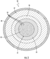
- an optical fiber distributed sensing system 20 includes an optical fiber 30 for distributed sensing.
- the optical fiber 30 illustratively includes a core 31 that includes glass 32 and diamond particles with nitrogen-vacancy (NV) centers 33 distributed within the glass.
- the diamond particles with NV centers 33 may in the form of a nano-diamond powder including nanometer or micron sized particles with NV defects.
- a first glass layer 35 surrounds the core 31.
- the first glass layer 35 may be the same glass material as the core 31, for example, silica or tellurite.
- the first glass layer 35 is devoid of diamond particles with NV centers 33.
- the first glass layer 35 provides an open region for light to propagate to a second glass layer 36 surrounding the first glass layer 35.
- the second glass layer 36 includes field-dependent index changing material, for example, lithium niobate or doped silicon.
- the second glass layer 36 guides a fraction of the light to an end of the fiber for detection.
- a third glass layer 37 surrounds the second glass layer 36.
- the third glass layer 37 functions as an outer coating and may include the same glass material as the first and second glass layers 35, 36.
- An outer jacket 38 may surround the optical fiber 30.
- An optical source in the form of an optical emitter 40, is coupled to the optical fiber 30 and operable from an end 34 thereof.
- the optical emitter 40 may be a pulsed laser, for example, a green laser, to optically excite the NV electrons for fluorescence collection, as will be appreciated by those skilled in the art.
- the green light or excitation may be modulated using a high-frequency amplitude or phase modulation, for example).
- the optical emitter 40 excites the embedded nanodiamonds or diamond particles with NV centers 33. NV fluorescence is guided through the core for higher efficiency detection, as will be appreciated by those skilled in the art.
- An optical detector 50 is coupled to the optical fiber 30 to detect fluorescence therefrom.
- the optical detector is illustratively at an end 41 of the optical fiber 30 opposite the end 34 at which the optical emitter 40 is operable from.
- the optical detector 50 includes one or more photodiodes 51 and an associated filter 52. More particularly, the filter 52 may be coupled between the end 41 of the optical fiber 30 and the photodiodes 51.
- the filter 52 may a green notch filter, particularly when the optical emitter 40 is in the form of a green pulsed laser.
- the filter 52 and the photodiodes 51 cooperate to detect relevant portions of the NV signal.
- frequency domain channel equalization techniques may be used with the modulation patterns to resolve, in time, the origin and strength of signal perturbations along the distributed sensing system.
- cumulative NV fluorescence spectrum is collected at the end 41 of the optical fiber 30 and processed to determine the location and strength of microwave perturbation.
- a magnetic field generator 60 is adjacent the optical fiber 30.
- the magnetic field generator 60 a magnetic field, such as generated by a direct current (DC).
- the strength of the DC magnetic field applied by the magnetic field generator may be adjustable and defines the microwave resonance frequencies to which the NV centers of the diamond particles with NV centers 33 are sensitive.
- the magnetic field generator 60 may be internal to the optical fiber 30 such as, for example, by way of wire conductors running across the system, or may be external, such as, for example, a separate source.
- a microwave source may be included and may function to activate electrons by populating them in certain spin states.
- the microwave source may be external to the optical fiber 30. Such a configuration would allow for magnetic field anomaly sensing in the vicinity of the optical fiber 30 while the microwave source is being applied, thereby creating a dual-purpose sensing capability.
- the optical source 40' may be in the form of optical emitters 45a'-45n' (e.g. a micro-light emitting diode (LED) array) along a length of the optical fiber 30'.
- Associated wiring 46' is accessible at the end 34' of the optical fiber 30', for example, for coupling to an optical source controller 47'. Excitation is applied at different regions along the optical fiber 30' from the optical emitters 45a'-45n'.
- the core 30' including glass 32' diamond particles with NV centers 33', the first glass layer 35' surrounding the core, the optical detector 50' including the photodiode 51' and filter 52' are similar to those described above.
- an outer jacket 38' may surround the optical fiber 30'.
- a magnetic field controller 61' may be coupled to the magnetic field generator 60' by way of associated wiring 62' accessible at the end 34' of the optical fiber 30' for controlling the magnetic field generator.
- the magnetic field generator 60' is similar to the magnetic field generator described above.
- the optical fiber distributed sensing system 20 may advantageously address the desire for microwave field sensing and spectral analysis by embedding the diamond particles with NV centers 33 into optical glass and drawing out a compound distributed sensing system.
- the system 20 may be particularly advantageous in underground and underwater environments, as will be appreciated by those skilled in the art.
- the system 20 may also permit sensing of relatively low power strengths as well as signal frequency content in the GHz range, for example.
- the dual purpose of the system 20 functions as both a microwave field sensor and a signal analyzer, such as for long-range distributive sensing.
- the system 20 may also advantageously use time-resolved signal processing techniques to interpret microwave field perturbations in the collected NV fluorescence signal.
- a method aspect is directed to a method for distributed sensing.
- the method includes positioning an optical fiber 30 for distributed sensing.
- the optical fiber 30 includes a core 31 that includes glass 32 and a plurality of diamond particles with nitrogen-vacancy (NV) centers 33 distributed within the glass 32, and at least one glass layer 35-37 surrounding the core.
- the method also includes coupling an optical source 40 to the optical fiber 30 and operable from an end 41 thereof, and coupling an optical detector 50 to the optical fiber 30 to detect fluorescence therefrom.
- NV nitrogen-vacancy
Landscapes
- Physics & Mathematics (AREA)
- General Physics & Mathematics (AREA)
- Electromagnetism (AREA)
- Engineering & Computer Science (AREA)
- Power Engineering (AREA)
- Condensed Matter Physics & Semiconductors (AREA)
- Investigating, Analyzing Materials By Fluorescence Or Luminescence (AREA)
Claims (10)
- Ein faseroptisches verteiltes Sensorsystem (20), das Folgendes umfasst:eine optische Faser (30) zur verteilten Abtastung mit
einem Kern (31), der Glas (32) enthält, undmindestens eine Glasschicht (35, 36, 37), die den Kern (31) umgibt, wobei die mindestens eine Glasschicht (35, 36, 37), die den Kern (31) umgibt, umfasst: eine erste Glasschicht (35), die den Kern (31) umgibt; und eine zweite Glasschicht (36), die die erste Glasschicht (35) umgibt;eine optische Quelle (40), die mit der optischen Faser (30) gekoppelt ist und von einem Ende (34) derselben aus betreibbar ist; dadurch gekennzeichnet, dass der Kern (31) eine Vielzahl von Diamantpartikeln mit Stickstoff-Leerstellen (NV-Zentren) (33) umfasst, die innerhalb des Glases (32) verteilt sind, dass die erste Glasschicht (35) frei von Diamantpartikeln mit NV-Zentren (33) ist, dass die zweite Glasschicht (36) ein feldabhängiges, den Index veränderndes Material umfasst; und dass das faseroptische verteilte Sensorsystem (2)einen optischen Detektor (50) umfasst, der mit der optischen Faser (30) gekoppelt ist, um deren Fluoreszenz zu erfassen. - Das faseroptische verteilte Sensorsystem (20) nach Anspruch 1, wobei die mindestens eine Glasschicht (35, 36, 37), die den Kern umgibt, eine dritte Glasschicht (37) umfasst, die die zweite Glasschicht (36) umgibt.
- Das faseroptische verteilte Sensorsystem (20) nach Anspruch 1, wobei die optische Quelle (40) einen optischen Emitter am Ende der optischen Faser umfasst.
- Das faseroptische verteilte Sensorsystem (20) nach Anspruch 1, wobei die optische Quelle (40) eine Vielzahl von optischen Emittern, die entlang einer Länge der optischen Faser (30) befestigt sind, und eine zugehörige Verdrahtung umfasst, die am Ende der optischen Faser (30) zugänglich ist.
- Das faseroptische verteilte Sensorsystem (20) nach Anspruch 1, wobei sich der optische Detektor (50) an einem Ende (41) der optischen Faser (30) befindet, das dem Ende (34) gegenüberliegt, von dem aus die optische Quelle (40) betrieben werden kann.
- Das faseroptische verteilte Sensorsystem (20) nach Anspruch 1, wobei das feldabhängige indexändernde Material Lithiumniobat oder dotiertes Silizium enthält.
- Ein Verfahren zur verteilten Abtastung, umfassend:Positionierung einer optischen Faser (30) zur verteilten Abtastung, wobei die optische Faser Folgendes umfassteinen Kern (31), der Glas (32) und eine Vielzahl von Diamantpartikeln mit in dem Glas verteilten Stickstoff-Leerstellen (NV-Zentren) (33) umfasst, undmindestens eine Glasschicht (35, 36, 37), die den Kern umgibt, wobei die mindestens eine Glasschicht, die den Kern umgibt, Folgendes umfasst: eine erste Glasschicht (35), die den Kern umgibt und frei von Diamantpartikeln mit NV-Zentren ist; und eine zweite Glasschicht (36), die die erste Glasschicht umgibt und ein feldabhängiges Indexänderungsmaterial umfasst;Ankoppeln einer optischen Quelle (40) an die optische Faser, die von einem Ende der Faser aus bedient werden kann; undAnkoppeln eines optischen Detektors (50) an die optische Faser, um deren Fluoreszenz zu erfassen.
- Das Verfahren nach Anspruch 7, wobei die mindestens eine Glasschicht, die den Kern umgibt, eine dritte Glasschicht umfasst, die die zweite Glasschicht umgibt.
- Das Verfahren nach Anspruch 7, bei dem das Ankoppeln der optischen Quelle das Ankoppeln eines optischen Senders an das Ende der optischen Faser umfasst.
- Das Verfahren nach Anspruch 6, wobei das feldabhängig indexändernde Material Lithiumniobat oder dotiertes Silizium enthält.
Applications Claiming Priority (1)
| Application Number | Priority Date | Filing Date | Title |
|---|---|---|---|
| US17/480,667 US12174274B2 (en) | 2021-09-21 | 2021-09-21 | Optical fiber sensing system having glass distributed diamond particles with nitrogen-vacancy (NV) centers and related methods |
Publications (2)
| Publication Number | Publication Date |
|---|---|
| EP4151963A1 EP4151963A1 (de) | 2023-03-22 |
| EP4151963B1 true EP4151963B1 (de) | 2024-08-28 |
Family
ID=82595186
Family Applications (1)
| Application Number | Title | Priority Date | Filing Date |
|---|---|---|---|
| EP22176912.8A Active EP4151963B1 (de) | 2021-09-21 | 2022-06-02 | Faseroptisches sensorsystem, das im glas verteilte diamantpartikel mit stickstoff-vakanten (nv) zentren aufweist, und zugehörige verfahren |
Country Status (2)
| Country | Link |
|---|---|
| US (1) | US12174274B2 (de) |
| EP (1) | EP4151963B1 (de) |
Families Citing this family (2)
| Publication number | Priority date | Publication date | Assignee | Title |
|---|---|---|---|---|
| PL449817A1 (pl) * | 2024-09-13 | 2026-03-16 | Uniwersytet Jagielloński | Układ do wykrywania położenia źródła pola magnetycznego oraz sposób wykrywania położenia źródła pola magnetycznego |
| CN120176823B (zh) * | 2025-03-28 | 2026-05-08 | 哈尔滨工程大学 | 基于金刚石氮空位色心的光纤水下声磁集成探测传感器 |
Family Cites Families (9)
| Publication number | Priority date | Publication date | Assignee | Title |
|---|---|---|---|---|
| EP1231488B1 (de) * | 2001-02-09 | 2010-03-31 | Panasonic Corporation | Optische Vorrichtung |
| US20070277730A1 (en) * | 2004-03-02 | 2007-12-06 | James Rabeau | Photon Source |
| US7526166B2 (en) * | 2007-01-31 | 2009-04-28 | Corning Incorporated | High numerical aperture fiber |
| CA2692017A1 (en) | 2007-07-02 | 2009-03-26 | Drexel University | Nanodiamond compositions and methods of making and using thereof |
| WO2014051886A1 (en) * | 2012-08-22 | 2014-04-03 | President And Fellows Of Harvard College | Nanoscale scanning sensors |
| US9910105B2 (en) | 2014-03-20 | 2018-03-06 | Lockheed Martin Corporation | DNV magnetic field detector |
| CN104360152B (zh) * | 2014-11-13 | 2017-04-12 | 北京航空航天大学 | 一种基于nv色心金刚石的微波传感器 |
| DE102015208151A1 (de) * | 2015-05-04 | 2016-11-10 | Robert Bosch Gmbh | Verfahren zum Messen eines elektrischen Stroms und Stromsensor |
| CN110510885A (zh) | 2019-08-28 | 2019-11-29 | 山东省科学院激光研究所 | 一种光纤式nv色心单/多光子源的制备方法 |
-
2021
- 2021-09-21 US US17/480,667 patent/US12174274B2/en active Active
-
2022
- 2022-06-02 EP EP22176912.8A patent/EP4151963B1/de active Active
Also Published As
| Publication number | Publication date |
|---|---|
| US20230089146A1 (en) | 2023-03-23 |
| EP4151963A1 (de) | 2023-03-22 |
| US12174274B2 (en) | 2024-12-24 |
Similar Documents
| Publication | Publication Date | Title |
|---|---|---|
| CN116113839B (zh) | 量子传感器 | |
| EP4151963A1 (de) | Faseroptisches sensorsystem, das im glas verteilte diamantpartikel mit stickstoff-vakanten (nv) zentren aufweist, und zugehörige verfahren | |
| US8138756B2 (en) | Microfiber magnetometer | |
| US7933022B2 (en) | Integrated optical disk resonator | |
| US7903906B2 (en) | Optical sensing devices and methods | |
| CN113804941A (zh) | 基于金刚石nv色心的光纤电流互感器及测量方法 | |
| US7113659B2 (en) | Efficient distributed sensor fiber | |
| JP2007183644A (ja) | 極薄導波路及び光ファイバを用いたセンサ | |
| JP2008500534A (ja) | 広帯域光源で励起される誘電体微小空洞蛍光センサ | |
| Lee et al. | Slope-assisted Brillouin optical correlation-domain reflectometry using polymer optical fibers with high propagation loss | |
| CN114112100B (zh) | 一种温度敏感触头及分布式温度传感系统 | |
| CN111273204B (zh) | 宽温区ac场增强dc场传感精度的谐振腔磁场传感系统 | |
| EP2378298A1 (de) | Einrichtung zur messung des elektrischen felds | |
| EP3425358A1 (de) | Multimodale optische faser, verwendung davon und system zur temperaturmessung | |
| JP2009104135A (ja) | 作用物質の存在を検出する装置及び方法 | |
| Handerek et al. | Improved optical power budget in distributed acoustic sensing using enhanced scattering optical fibre | |
| EP4302014B1 (de) | Verfahren und vorrichtung zur integration eines diamanten mit einer led zur on-chip-quantenmessung | |
| Liang et al. | Temperature and acoustic impedance simultaneous sensing based on FBS in coated optical fiber | |
| CN119804944A (zh) | 一种量子电流传感器及电流测量方法 | |
| CN117949875A (zh) | 片上光力磁力仪及制备方法 | |
| CN111474506A (zh) | 一种共面波导磁场探测器 | |
| US10329147B2 (en) | Surface plasmon-based nanosensors and systems and methods for sensing photons and chemical or biological agents | |
| CN119224407B (zh) | 一种基于碳化硅自旋缺陷的电流测量装置及电流测量方法 | |
| US12553959B2 (en) | Sensing system having a MEMS nitrogen vacancy sensing device and related methods | |
| Li et al. | Mechanical Resonance Multiplexed Magnetic Communication via Magnetoelastic Heterostructured WGM Resonator |
Legal Events
| Date | Code | Title | Description |
|---|---|---|---|
| PUAI | Public reference made under article 153(3) epc to a published international application that has entered the european phase |
Free format text: ORIGINAL CODE: 0009012 |
|
| STAA | Information on the status of an ep patent application or granted ep patent |
Free format text: STATUS: REQUEST FOR EXAMINATION WAS MADE |
|
| 17P | Request for examination filed |
Effective date: 20220602 |
|
| AK | Designated contracting states |
Kind code of ref document: A1 Designated state(s): AL AT BE BG CH CY CZ DE DK EE ES FI FR GB GR HR HU IE IS IT LI LT LU LV MC MK MT NL NO PL PT RO RS SE SI SK SM TR |
|
| STAA | Information on the status of an ep patent application or granted ep patent |
Free format text: STATUS: EXAMINATION IS IN PROGRESS |
|
| 17Q | First examination report despatched |
Effective date: 20231106 |
|
| GRAP | Despatch of communication of intention to grant a patent |
Free format text: ORIGINAL CODE: EPIDOSNIGR1 |
|
| STAA | Information on the status of an ep patent application or granted ep patent |
Free format text: STATUS: GRANT OF PATENT IS INTENDED |
|
| RIC1 | Information provided on ipc code assigned before grant |
Ipc: G02B 6/12 20060101ALN20240521BHEP Ipc: G02B 6/036 20060101ALN20240521BHEP Ipc: G01H 9/00 20060101AFI20240521BHEP |
|
| RIC1 | Information provided on ipc code assigned before grant |
Ipc: G02B 6/12 20060101ALN20240524BHEP Ipc: G02B 6/036 20060101ALN20240524BHEP Ipc: G01H 9/00 20060101AFI20240524BHEP |
|
| INTG | Intention to grant announced |
Effective date: 20240612 |
|
| GRAS | Grant fee paid |
Free format text: ORIGINAL CODE: EPIDOSNIGR3 |
|
| GRAA | (expected) grant |
Free format text: ORIGINAL CODE: 0009210 |
|
| STAA | Information on the status of an ep patent application or granted ep patent |
Free format text: STATUS: THE PATENT HAS BEEN GRANTED |
|
| AK | Designated contracting states |
Kind code of ref document: B1 Designated state(s): AL AT BE BG CH CY CZ DE DK EE ES FI FR GB GR HR HU IE IS IT LI LT LU LV MC MK MT NL NO PL PT RO RS SE SI SK SM TR |
|
| P01 | Opt-out of the competence of the unified patent court (upc) registered |
Free format text: CASE NUMBER: APP_43103/2024 Effective date: 20240723 |
|
| REG | Reference to a national code |
Ref country code: CH Ref legal event code: EP |
|
| REG | Reference to a national code |
Ref country code: DE Ref legal event code: R096 Ref document number: 602022005604 Country of ref document: DE |
|
| REG | Reference to a national code |
Ref country code: IE Ref legal event code: FG4D |
|
| REG | Reference to a national code |
Ref country code: LT Ref legal event code: MG9D |
|
| PG25 | Lapsed in a contracting state [announced via postgrant information from national office to epo] |
Ref country code: NO Free format text: LAPSE BECAUSE OF FAILURE TO SUBMIT A TRANSLATION OF THE DESCRIPTION OR TO PAY THE FEE WITHIN THE PRESCRIBED TIME-LIMIT Effective date: 20241128 |
|
| REG | Reference to a national code |
Ref country code: AT Ref legal event code: MK05 Ref document number: 1718416 Country of ref document: AT Kind code of ref document: T Effective date: 20240828 |
|
| PG25 | Lapsed in a contracting state [announced via postgrant information from national office to epo] |
Ref country code: FI Free format text: LAPSE BECAUSE OF FAILURE TO SUBMIT A TRANSLATION OF THE DESCRIPTION OR TO PAY THE FEE WITHIN THE PRESCRIBED TIME-LIMIT Effective date: 20240828 Ref country code: NL Free format text: LAPSE BECAUSE OF FAILURE TO SUBMIT A TRANSLATION OF THE DESCRIPTION OR TO PAY THE FEE WITHIN THE PRESCRIBED TIME-LIMIT Effective date: 20240828 Ref country code: PL Free format text: LAPSE BECAUSE OF FAILURE TO SUBMIT A TRANSLATION OF THE DESCRIPTION OR TO PAY THE FEE WITHIN THE PRESCRIBED TIME-LIMIT Effective date: 20240828 Ref country code: GR Free format text: LAPSE BECAUSE OF FAILURE TO SUBMIT A TRANSLATION OF THE DESCRIPTION OR TO PAY THE FEE WITHIN THE PRESCRIBED TIME-LIMIT Effective date: 20241129 Ref country code: PT Free format text: LAPSE BECAUSE OF FAILURE TO SUBMIT A TRANSLATION OF THE DESCRIPTION OR TO PAY THE FEE WITHIN THE PRESCRIBED TIME-LIMIT Effective date: 20241230 |
|
| PG25 | Lapsed in a contracting state [announced via postgrant information from national office to epo] |
Ref country code: BG Free format text: LAPSE BECAUSE OF FAILURE TO SUBMIT A TRANSLATION OF THE DESCRIPTION OR TO PAY THE FEE WITHIN THE PRESCRIBED TIME-LIMIT Effective date: 20240828 |
|
| PG25 | Lapsed in a contracting state [announced via postgrant information from national office to epo] |
Ref country code: LV Free format text: LAPSE BECAUSE OF FAILURE TO SUBMIT A TRANSLATION OF THE DESCRIPTION OR TO PAY THE FEE WITHIN THE PRESCRIBED TIME-LIMIT Effective date: 20240828 |
|
| REG | Reference to a national code |
Ref country code: NL Ref legal event code: MP Effective date: 20240828 |
|
| PG25 | Lapsed in a contracting state [announced via postgrant information from national office to epo] |
Ref country code: AT Free format text: LAPSE BECAUSE OF FAILURE TO SUBMIT A TRANSLATION OF THE DESCRIPTION OR TO PAY THE FEE WITHIN THE PRESCRIBED TIME-LIMIT Effective date: 20240828 Ref country code: IS Free format text: LAPSE BECAUSE OF FAILURE TO SUBMIT A TRANSLATION OF THE DESCRIPTION OR TO PAY THE FEE WITHIN THE PRESCRIBED TIME-LIMIT Effective date: 20241228 |
|
| PG25 | Lapsed in a contracting state [announced via postgrant information from national office to epo] |
Ref country code: HR Free format text: LAPSE BECAUSE OF FAILURE TO SUBMIT A TRANSLATION OF THE DESCRIPTION OR TO PAY THE FEE WITHIN THE PRESCRIBED TIME-LIMIT Effective date: 20240828 |
|
| PG25 | Lapsed in a contracting state [announced via postgrant information from national office to epo] |
Ref country code: ES Free format text: LAPSE BECAUSE OF FAILURE TO SUBMIT A TRANSLATION OF THE DESCRIPTION OR TO PAY THE FEE WITHIN THE PRESCRIBED TIME-LIMIT Effective date: 20240828 Ref country code: RS Free format text: LAPSE BECAUSE OF FAILURE TO SUBMIT A TRANSLATION OF THE DESCRIPTION OR TO PAY THE FEE WITHIN THE PRESCRIBED TIME-LIMIT Effective date: 20241128 |
|
| PG25 | Lapsed in a contracting state [announced via postgrant information from national office to epo] |
Ref country code: RS Free format text: LAPSE BECAUSE OF FAILURE TO SUBMIT A TRANSLATION OF THE DESCRIPTION OR TO PAY THE FEE WITHIN THE PRESCRIBED TIME-LIMIT Effective date: 20241128 Ref country code: PT Free format text: LAPSE BECAUSE OF FAILURE TO SUBMIT A TRANSLATION OF THE DESCRIPTION OR TO PAY THE FEE WITHIN THE PRESCRIBED TIME-LIMIT Effective date: 20241230 Ref country code: PL Free format text: LAPSE BECAUSE OF FAILURE TO SUBMIT A TRANSLATION OF THE DESCRIPTION OR TO PAY THE FEE WITHIN THE PRESCRIBED TIME-LIMIT Effective date: 20240828 Ref country code: NO Free format text: LAPSE BECAUSE OF FAILURE TO SUBMIT A TRANSLATION OF THE DESCRIPTION OR TO PAY THE FEE WITHIN THE PRESCRIBED TIME-LIMIT Effective date: 20241128 Ref country code: NL Free format text: LAPSE BECAUSE OF FAILURE TO SUBMIT A TRANSLATION OF THE DESCRIPTION OR TO PAY THE FEE WITHIN THE PRESCRIBED TIME-LIMIT Effective date: 20240828 Ref country code: LV Free format text: LAPSE BECAUSE OF FAILURE TO SUBMIT A TRANSLATION OF THE DESCRIPTION OR TO PAY THE FEE WITHIN THE PRESCRIBED TIME-LIMIT Effective date: 20240828 Ref country code: IS Free format text: LAPSE BECAUSE OF FAILURE TO SUBMIT A TRANSLATION OF THE DESCRIPTION OR TO PAY THE FEE WITHIN THE PRESCRIBED TIME-LIMIT Effective date: 20241228 Ref country code: HR Free format text: LAPSE BECAUSE OF FAILURE TO SUBMIT A TRANSLATION OF THE DESCRIPTION OR TO PAY THE FEE WITHIN THE PRESCRIBED TIME-LIMIT Effective date: 20240828 Ref country code: GR Free format text: LAPSE BECAUSE OF FAILURE TO SUBMIT A TRANSLATION OF THE DESCRIPTION OR TO PAY THE FEE WITHIN THE PRESCRIBED TIME-LIMIT Effective date: 20241129 Ref country code: FI Free format text: LAPSE BECAUSE OF FAILURE TO SUBMIT A TRANSLATION OF THE DESCRIPTION OR TO PAY THE FEE WITHIN THE PRESCRIBED TIME-LIMIT Effective date: 20240828 Ref country code: ES Free format text: LAPSE BECAUSE OF FAILURE TO SUBMIT A TRANSLATION OF THE DESCRIPTION OR TO PAY THE FEE WITHIN THE PRESCRIBED TIME-LIMIT Effective date: 20240828 Ref country code: BG Free format text: LAPSE BECAUSE OF FAILURE TO SUBMIT A TRANSLATION OF THE DESCRIPTION OR TO PAY THE FEE WITHIN THE PRESCRIBED TIME-LIMIT Effective date: 20240828 Ref country code: AT Free format text: LAPSE BECAUSE OF FAILURE TO SUBMIT A TRANSLATION OF THE DESCRIPTION OR TO PAY THE FEE WITHIN THE PRESCRIBED TIME-LIMIT Effective date: 20240828 |
|
| PG25 | Lapsed in a contracting state [announced via postgrant information from national office to epo] |
Ref country code: DK Free format text: LAPSE BECAUSE OF FAILURE TO SUBMIT A TRANSLATION OF THE DESCRIPTION OR TO PAY THE FEE WITHIN THE PRESCRIBED TIME-LIMIT Effective date: 20240828 Ref country code: RO Free format text: LAPSE BECAUSE OF FAILURE TO SUBMIT A TRANSLATION OF THE DESCRIPTION OR TO PAY THE FEE WITHIN THE PRESCRIBED TIME-LIMIT Effective date: 20240828 Ref country code: SM Free format text: LAPSE BECAUSE OF FAILURE TO SUBMIT A TRANSLATION OF THE DESCRIPTION OR TO PAY THE FEE WITHIN THE PRESCRIBED TIME-LIMIT Effective date: 20240828 |
|
| PG25 | Lapsed in a contracting state [announced via postgrant information from national office to epo] |
Ref country code: EE Free format text: LAPSE BECAUSE OF FAILURE TO SUBMIT A TRANSLATION OF THE DESCRIPTION OR TO PAY THE FEE WITHIN THE PRESCRIBED TIME-LIMIT Effective date: 20240828 |
|
| PG25 | Lapsed in a contracting state [announced via postgrant information from national office to epo] |
Ref country code: CZ Free format text: LAPSE BECAUSE OF FAILURE TO SUBMIT A TRANSLATION OF THE DESCRIPTION OR TO PAY THE FEE WITHIN THE PRESCRIBED TIME-LIMIT Effective date: 20240828 |
|
| PG25 | Lapsed in a contracting state [announced via postgrant information from national office to epo] |
Ref country code: SK Free format text: LAPSE BECAUSE OF FAILURE TO SUBMIT A TRANSLATION OF THE DESCRIPTION OR TO PAY THE FEE WITHIN THE PRESCRIBED TIME-LIMIT Effective date: 20240828 Ref country code: IT Free format text: LAPSE BECAUSE OF FAILURE TO SUBMIT A TRANSLATION OF THE DESCRIPTION OR TO PAY THE FEE WITHIN THE PRESCRIBED TIME-LIMIT Effective date: 20240828 |
|
| REG | Reference to a national code |
Ref country code: DE Ref legal event code: R097 Ref document number: 602022005604 Country of ref document: DE |
|
| PLBE | No opposition filed within time limit |
Free format text: ORIGINAL CODE: 0009261 |
|
| STAA | Information on the status of an ep patent application or granted ep patent |
Free format text: STATUS: NO OPPOSITION FILED WITHIN TIME LIMIT |
|
| PGFP | Annual fee paid to national office [announced via postgrant information from national office to epo] |
Ref country code: DE Payment date: 20250627 Year of fee payment: 4 |
|
| 26N | No opposition filed |
Effective date: 20250530 |
|
| PG25 | Lapsed in a contracting state [announced via postgrant information from national office to epo] |
Ref country code: SE Free format text: LAPSE BECAUSE OF FAILURE TO SUBMIT A TRANSLATION OF THE DESCRIPTION OR TO PAY THE FEE WITHIN THE PRESCRIBED TIME-LIMIT Effective date: 20240828 |
|
| REG | Reference to a national code |
Ref country code: CH Ref legal event code: H13 Free format text: ST27 STATUS EVENT CODE: U-0-0-H10-H13 (AS PROVIDED BY THE NATIONAL OFFICE) Effective date: 20260127 |
|
| PG25 | Lapsed in a contracting state [announced via postgrant information from national office to epo] |
Ref country code: MC Free format text: LAPSE BECAUSE OF FAILURE TO SUBMIT A TRANSLATION OF THE DESCRIPTION OR TO PAY THE FEE WITHIN THE PRESCRIBED TIME-LIMIT Effective date: 20240828 |
|
| PG25 | Lapsed in a contracting state [announced via postgrant information from national office to epo] |
Ref country code: LU Free format text: LAPSE BECAUSE OF NON-PAYMENT OF DUE FEES Effective date: 20250602 |
|
| REG | Reference to a national code |
Ref country code: BE Ref legal event code: MM Effective date: 20250630 |
|
| PG25 | Lapsed in a contracting state [announced via postgrant information from national office to epo] |
Ref country code: IE Free format text: LAPSE BECAUSE OF NON-PAYMENT OF DUE FEES Effective date: 20250602 |
|
| PG25 | Lapsed in a contracting state [announced via postgrant information from national office to epo] |
Ref country code: BE Free format text: LAPSE BECAUSE OF NON-PAYMENT OF DUE FEES Effective date: 20250630 |
|
| PG25 | Lapsed in a contracting state [announced via postgrant information from national office to epo] |
Ref country code: FR Free format text: LAPSE BECAUSE OF NON-PAYMENT OF DUE FEES Effective date: 20250630 |
|
| PG25 | Lapsed in a contracting state [announced via postgrant information from national office to epo] |
Ref country code: CH Free format text: LAPSE BECAUSE OF NON-PAYMENT OF DUE FEES Effective date: 20250630 |