EP4151855A1 - Wind turbine blade, wind turbine blade monitoring device, wind power generation device, and wind turbine blade monitoring method - Google Patents
Wind turbine blade, wind turbine blade monitoring device, wind power generation device, and wind turbine blade monitoring method Download PDFInfo
- Publication number
- EP4151855A1 EP4151855A1 EP21882796.2A EP21882796A EP4151855A1 EP 4151855 A1 EP4151855 A1 EP 4151855A1 EP 21882796 A EP21882796 A EP 21882796A EP 4151855 A1 EP4151855 A1 EP 4151855A1
- Authority
- EP
- European Patent Office
- Prior art keywords
- magnetic field
- wind turbine
- blade
- turbine blade
- pair
- Prior art date
- Legal status (The legal status is an assumption and is not a legal conclusion. Google has not performed a legal analysis and makes no representation as to the accuracy of the status listed.)
- Granted
Links
Images



Classifications
-
- F—MECHANICAL ENGINEERING; LIGHTING; HEATING; WEAPONS; BLASTING
- F03—MACHINES OR ENGINES FOR LIQUIDS; WIND, SPRING, OR WEIGHT MOTORS; PRODUCING MECHANICAL POWER OR A REACTIVE PROPULSIVE THRUST, NOT OTHERWISE PROVIDED FOR
- F03D—WIND MOTORS
- F03D17/00—Monitoring or testing of wind motors, e.g. diagnostics
-
- F—MECHANICAL ENGINEERING; LIGHTING; HEATING; WEAPONS; BLASTING
- F03—MACHINES OR ENGINES FOR LIQUIDS; WIND, SPRING, OR WEIGHT MOTORS; PRODUCING MECHANICAL POWER OR A REACTIVE PROPULSIVE THRUST, NOT OTHERWISE PROVIDED FOR
- F03D—WIND MOTORS
- F03D80/00—Details, components or accessories not provided for in groups F03D1/00 - F03D17/00
- F03D80/30—Lightning protection
-
- Y—GENERAL TAGGING OF NEW TECHNOLOGICAL DEVELOPMENTS; GENERAL TAGGING OF CROSS-SECTIONAL TECHNOLOGIES SPANNING OVER SEVERAL SECTIONS OF THE IPC; TECHNICAL SUBJECTS COVERED BY FORMER USPC CROSS-REFERENCE ART COLLECTIONS [XRACs] AND DIGESTS
- Y02—TECHNOLOGIES OR APPLICATIONS FOR MITIGATION OR ADAPTATION AGAINST CLIMATE CHANGE
- Y02E—REDUCTION OF GREENHOUSE GAS [GHG] EMISSIONS, RELATED TO ENERGY GENERATION, TRANSMISSION OR DISTRIBUTION
- Y02E10/00—Energy generation through renewable energy sources
- Y02E10/70—Wind energy
- Y02E10/72—Wind turbines with rotation axis in wind direction
Definitions
- the present disclosure relates to a wind turbine blade, a monitoring apparatus for the wind turbine blade and a wind power generating apparatus, and a monitoring method for the wind turbine blade.
- a wind turbine blade is provided with a receptor (lightning receiving part) as a device for protecting the wind turbine blade from lightning.
- the receptor is disposed at a tip portion of the wind turbine blade or another location, and is electrically connected to a down conductor (pull-down conductor) extending through the wind turbine blade and a wind turbine tower.
- a lightning current when lightning strikes the receptor is guided to the ground via the down conductor and discharged.
- Patent Document 1 discloses a system for detecting lightning strikes on wind turbine rotor blades provided with a plurality of receptors.
- the system for detecting lightning strikes includes a plurality of current sensors respectively provided in correspondence with the plurality of receptors.
- the plurality of current sensors respectively, detect currents flowing through branch lines (conductors) respectively connecting between the plurality of receptors and conductors (down conductors) extending inside the wind turbine blades. Then, based on detection results in the plurality of current sensors, the system detects that the wind turbine blade has been struck by lightning and identifies the lightning-struck receptor.
- Patent Document 1 US8258773B
- a wind turbine blade provided with a receptor may be struck by lightning at a location other than a location where the receptor is installed, for example, a surface of a blade body (shell or the like). Therefore, it is desirable to be able to appropriately identify the lightning-struck position in the wind turbine blade, in order to appropriately or quickly perform maintenance, for example, in case where the wind turbine blade is damaged by the lightning strike.
- Patent Document 1 the system for detecting lightning strikes described in Patent Document 1 does not take into consideration a case where lightning strikes a location other than the receptor, such as the surface of the blade body, and it is impossible to identify whether the lightning strikes either the receptor installation location or a location other than the receptor installation location.
- an object of at least one embodiment of the present invention is to provide a wind turbine blade whose lightning-struck position can appropriately be identified, a monitoring apparatus for the wind turbine blade and a wind power generating apparatus, and a monitoring method for the wind turbine blade.
- a wind turbine blade includes: a blade body; a down conductor extending along a longitudinal direction of the blade body; and at least a pair of magnetic field sensors disposed inside the blade body and at opposite positions across the down conductor, the pair of magnetic field sensors being configured to detect a local magnetic field at each of the positions.
- a monitoring apparatus for a wind turbine blade that includes a blade body and a down conductor extending along a longitudinal direction of the blade body, including: at least a pair of magnetic field sensors disposed inside the blade body and in the wind turbine blade at opposite positions across the down conductor, the pair of magnetic field sensors being configured to detect a local magnetic field at each of the positions; and a lightning-struck position information acquisition part for acquiring information about a lightning-struck position of the wind turbine blade, based on a detection signal of each of at least the pair of magnetic field sensors.
- a wind power generating apparatus includes: a wind turbine rotor including the above-described wind turbine blade; a generator configured to be driven by rotation of the wind turbine rotor; and a monitoring apparatus including a lightning-struck position information acquisition part for acquiring information about a lightning-struck position of the wind turbine blade, based on a detection signal of each of at least the pair of magnetic field sensors.
- a wind turbine blade whose lightning-struck position can appropriately be identified, a monitoring apparatus for the wind turbine blade and a wind power generating apparatus, and a monitoring method for the wind turbine blade.
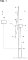
- FIG. 1 is a schematic view of a wind power generating apparatus to which a wind turbine blade or a monitoring apparatus is applied according to some embodiments.
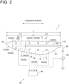
- FIGs. 2 and 3 are each a schematic view of the wind turbine blade according to an embodiment.
- FIG. 2 is a cross-sectional view orthogonal to the longitudinal direction of the wind turbine blade, and
- FIG. 3 shows a cross section taken along line A-A in FIG. 2 .
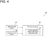
- FIG. 4 is a schematic configuration diagram of monitoring according to an embodiment.
- a wind power generating apparatus 1 includes a rotor (wind turbine rotor) 5 composed of at least one (for example, three) wind turbine blade 2 and a hub 4.
- the wind turbine blade 2 is radially mounted on a hub 4, and the wind turbine blade 2 receives wind to rotate the rotor 5 and drives a generator (not shown) connected to the rotor 5.
- the rotor 5 is supported by a nacelle 8 disposed on an upper side of a tower 6.
- the tower 6 may be disposed upright on a base structure, such as a foundation structure or a floating structure, disposed on water or on land.
- the wind turbine blade 2 includes a blade body 10 including a shell (casing), a down conductor 24 extending along the longitudinal direction of the blade body 10 (hereinafter, also simply referred to as the longitudinal direction), and at least a pair of magnetic field sensors 30 disposed inside the blade body 10.
- the blade body 10 includes a blade root 15 mounted on the hub 4 of the wind power generating apparatus 1, a blade tip 16 located farthest from the hub 4, and an airfoil portion extending between the blade root 15 and the blade tip 16. Further, as shown in FIGs. 2 and 3 , the blade body 10 has a leading edge 11 and a trailing edge 12 from the blade root 15 to the blade tip 16. Furthermore, an exterior shape of the blade body 10 is formed by a suction surface (convex surface) 13 and a pressure surface (concave surface) 14. The suction surface 13 and the pressure surface 14 of the blade body 10 include a surface of the shell.
- the blade body 10 may be formed from fiber reinforced plastic.
- the blade body 10 is provided with receptors (lightning receiving parts) 20.
- the receptors 20 are formed from an electrically conductive material, and is typically made from metal.
- the receptors 20 may include a receptor 21 disposed in an area including the blade tip 16, and/or a receptor 22 disposed on the surface (the suction surface 13 or the pressure surface 14) of the blade body 10 at a position between the area and the blade root 15 in the longitudinal direction.
- the down conductor 24 of the wind turbine blade 2 is composed of, for example, a conducting wire, electrically connected to each of the above-described receptors 20, and connected to a down conductor 26 extending inside the tower 6.
- a lightning current when lightning strikes the wind turbine blade 2 (the receptors 20 or the like) is guided to the outside of the wind power generating apparatus 1 such as the earth (ground) via the down conductor 24 and the down conductor 26.
- the down conductor 24 may extend inside the blade body 10 along the longitudinal direction, for example, as shown in FIG. 3 .
- the down conductor 24 may extend along the surface (the suction surface 13 or the pressure surface 14) of the blade body 10 along the longitudinal direction (see FIG. 6A, 6B ).
- At least the pair of magnetic field sensors 30 are disposed at positions on both sides across the down conductor 24 inside the blade body 10, and are configured to detect local magnetic fields at the respective positions. That is, each of the magnetic field sensors 30 is disposed at the position spaced apart from the down conductor 24 inside the blade body 10, and is configured to detect the direction of the magnetic field or the like at this position. Therefore, when the lightning current flows through the down conductor 24 or the blade body 10 and the magnetic field is generated around the lightning current, each of the above-described magnetic field sensors 30 can detect the direction of the magnetic field or the like at the installation position of the magnetic field sensor 30.
- the magnetic field sensors 30 may be supported by the shell or a spar of the blade body 10.
- the down conductor 24 is disposed inside the blade body 10, and a plurality of magnetic field sensors 30A to 30D are disposed inside the blade body 10 in a cross section orthogonal to the longitudinal direction.
- the magnetic field sensor 30A is disposed between the down conductor 24 and the suction surface 13
- the magnetic field sensor 30B is disposed between the down conductor 24 and the pressure surface 14
- the magnetic field sensor 30C is disposed between the down conductor 24 and the leading edge 11
- the magnetic field sensor 30D is disposed between the down conductor 24 and the trailing edge 12.
- Each of the magnetic field sensors 30 is a sensor capable of detecting the direction of the magnetic field at the installation position of the magnetic field sensor 30.
- a sensor having effective responsiveness to a frequency component of the lightning current can preferably be used.
- the magnetic field sensor 30 for example, a loop coil sensor, a B-dot sensor, or a hall element sensor can be used.
- the wind power generating apparatus 1 may include a lightning current sensor 36 disposed on a path of a lightning current from the down conductor 24 toward the ground.
- the lightning current sensor 36 may be configured to detect the polarity (positive or negative) of the lightning current from down conductor 24 to the ground. Further, the lightning current sensor 36 may be configured to detect the magnitude of the above-described lightning current. Alternatively, the lightning current sensor 36 may be configured to measure a current value of the above-described lightning current.
- a processor such as a processing device 40 which will be described later, may identify the polarity of the lightning current or may identify the magnitude of the lightning current from a current waveform indicating a time change in current measurement value by the lightning current sensor 36.
- the lightning current sensor 36 is disposed between the ground and the down conductor 24 of the wind turbine blade 2.
- the lightning current sensor 36 may be disposed inside the blade body 10, or may be disposed inside the nacelle or inside the tower (see FIG. 1 ).
- the lightning current flowing through the blade body 10 toward the ground normally flows into the down conductor 24 before reaching the ground.
- the above-described lightning current sensor 36 can detect the polarity of the lightning current.
- the wind power generating apparatus 1 shown in FIG. 1 further includes a monitoring apparatus 50 for monitoring the wind turbine blade 2.
- the monitoring apparatus 50 includes at least the pair of magnetic field sensors 30 and/or the lightning current sensor 36 described above, and the processing device 40 for processing a signal detected by at least the pair of magnetic field sensors 30 and/or the lightning current sensor 36.
- the processing device 40 includes a lightning-struck position information acquisition part 42 configured to acquire information about a lightning-struck position of the wind turbine blade 2, based on the detection signal of at least the pair of magnetic field sensors 30 and/or the lightning current sensor 36.
- the detection signal from at least the pair of magnetic field sensors 30 and/or the lightning current sensor 36 may be transmitted to the processing device 40 by a cable, an optical fiber, or radio.
- the processing device 40 may include a calculator with a processor (such as CPU), a storage device (memory device; such as RAM), an auxiliary storage part, an interface, and the like.
- the processing device 40 receives the signal from at least the pair of magnetic field sensors 30 and/or the lightning current sensor 36 described above via the interface.
- the processor is configured to process the signal thus received.
- the processor is configured to process programs loaded into the storage device. Whereby, the function of the lightning-struck position information acquisition part 42 described above is realized.
- the processing contents in the processing device 40 may be implemented as programs executed by the processor.
- the programs may be stored in the auxiliary storage part. When executed, these programs are loaded into the storage device.
- the processor reads out the programs from the storage device to execute instructions included in the programs.
- the processing device 40 may be disposed inside the tower 6 or the nacelle 8 of the wind power generating apparatus 1. Alternatively, some or all of the functions of the processing device 40 may be disposed outside (remote location or the like) the wind power generating apparatus 1.
- At least the pair of magnetic field sensors 30 described above is used to detect a local magnetic field at the installation position of each of the magnetic field sensors 30. Then, based on the detection result of each of the magnetic field sensors 30, the above-described lightning-struck position information acquisition part 42 or the like acquires the information about the lightning-struck position of the wind turbine blade 2.
- FIGs. 5A and 5B , FIGs. 6A and 6B , FIG. 7 , and FIG. 8 are each a schematic cross-sectional view of the wind turbine blade 2 according to an embodiment, and are each a cross-sectional view orthogonal to the longitudinal direction of the wind turbine blade 2.
- the X axis is an axis in a direction connecting the leading edge 11 and the trailing edge 12 (that is, a chordwise direction of the wind turbine blade 2) (note that a direction from the leading edge 11 toward the trailing edge is positive)
- the Y axis is an axis in a direction orthogonal to the X axis (that is, a thickness direction of the wind turbine blade 2) (note that a direction from the pressure surface 14 toward the suction surface 13 is positive)
- the Z axis is an axis in a direction orthogonal to the X axis and the Y axis (that is, the longitudinal direction of the wind turbine blade 2) (note that a direction from the blade tip 16 side (the front side of the drawing) toward the blade root 15 side (the back side of the drawing) is positive).
- FIGs. 5A to 8 reference sign C indicates a lightning current
- reference sign M indicates a direction of a magnetic field generated around the lightning current.
- FIGs. 5A and 5B show the same cross section of the same wind turbine blade 2, but portions through which the lightning current flows are different. Specifically, the lightning current C flows through the down conductor 24 in FIG. 5A , whereas the lightning current C flows through the surface (more specifically, the surface on the suction surface 13 side in FIG. 5B ) of the blade body 10 in FIG. 5B . The same also applies to FIG. 6A and FIG. 6B .
- the lightning current C in FIGs. 5A to 8 is a positive polarity lightning current.
- the magnetic field M is generated around the lightning current C in the right (clockwise) direction on the drawing.
- At least the pair of magnetic field sensors 30 is disposed inside the blade body 10.
- the down conductor 24 is disposed inside the blade body 10.
- the magnetic field sensor 30A is the magnetic field sensor 30 disposed between the down conductor 24 and the suction surface 13
- the magnetic field sensor 30B is the magnetic field sensor 30 disposed between the down conductor 24 and the pressure surface 14
- the magnetic field sensor 30C is the magnetic field sensor 30 disposed between the down conductor 24 and the leading edge 11
- the magnetic field sensor 30D is the magnetic field sensor 30 disposed between the down conductor 24 and the trailing edge 12.
- the magnetic field M is generated around the lightning current C.
- the direction of the magnetic field M at the position of the magnetic field sensor 30 differs depending on a positional relationship between the magnetic field sensor 30 and the portion of the wind turbine blade 2 where the lightning current C flows.
- the at least one magnetic field sensor 30 includes a pair of magnetic field sensors 30 disposed on the both sides of the down conductor 24.
- a pair of magnetic field sensors 30A, 30B are disposed on the both sides of the down conductor 24 in the Y-axis direction (thickness direction).
- a pair of magnetic field sensors 30C, 30D are disposed on both sides of the down conductor 24 in the X-axis direction (chordwise direction).
- a pair of magnetic field sensors 30 are disposed on both sides of the down conductor 24, it is possible to determine whether the lightning current C has flowed through the down conductor 24.
- a pair of magnetic field sensors 30A, 30B or a pair of magnetic field sensors 30C, 30D detect the magnetic fields M in opposite directions.
- the positive polarity lightning current C flows through the blade body 10
- the directions of the magnetic fields M detected by a pair of magnetic field sensors 30 are no longer opposite to each other. Specifically, for example, as shown in FIG.
- both of a pair of magnetic field sensors 30A, 30B detect the magnetic fields M in the negative direction of the X axis.
- both of a pair of magnetic field sensors 30C, 30D detect the magnetic fields M in the negative direction of the Y axis.
- the lightning current C has flowed through the down conductor 24 when the directions of the magnetic fields M detected by the pair of magnetic field sensors 30 are opposite to each other. Further, it can be determined that the lightning current C has flowed through the portion (the blade body or the like) other than the down conductor 24 when the directions of the magnetic fields M detected by a pair of magnetic field sensors 30 are the same, and therefore, it can be identified that lightning has struck the location (blade body 10 or the like) other than the portion of the wind turbine blade 2 where the receptor 20 is installed. That is, it is possible to acquire the information about the lightning-struck position of the wind turbine blade 2. Thus, it is possible to appropriately identify the lightning-struck position in the wind turbine blade 2.
- the information about the lightning-struck position of the wind turbine blade 2 may be acquired based on the polarity of the lightning current C detected by the lightning current sensor 36.
- the lightning current C may have a positive polarity or may have a negative polarity, and depending on the polarity of the lightning current C, the direction of the magnetic field generated around the lightning current C differs. That is, FIGs. 5A to 8 show that the positive polarity lightning current C generates the magnetic field M in the right (clockwise) direction on the drawing, but in the case of a negative polarity lightning current, the magnetic field M is generated in the left (counterclockwise) direction on the drawing.
- the lightning current C has flowed through the blade body 10 on the suction surface 13 side (or the pressure surface 14 side)
- At least the pair of magnetic field sensors 30 includes a pair of first sensors disposed on a first axis passing through the installation position of the down conductor 24 in a cross section intersecting the longitudinal direction, and a pair of second sensors disposed on a second axis passing through the installation position of the down conductor 24 and orthogonal to the first axis in the same cross section.
- first sensors disposed on a first axis passing through the installation position of the down conductor 24 in a cross section intersecting the longitudinal direction
- second sensors disposed on a second axis passing through the installation position of the down conductor 24 and orthogonal to the first axis in the same cross section.
- At least the pair of magnetic field sensors 30 includes the magnetic field sensors 30C, 30D which are the a pair of first sensors disposed on the X axis (the first axis; indicated by a straight line Q2) passing through the installation position of the down conductor 24 in the cross section intersecting the longitudinal direction, and the magnetic field sensors 30A, 30B which are the a pair of second sensors disposed on the Y axis (the second axis; indicated by a straight line Q1) passing through the installation position of the down conductor 24 and orthogonal to the X axis (first axis) in the same cross section.
- the a pair of first sensors are disposed on the above-described X-axis (first axis) (for example, the X-axis) and the a pair of second sensors (magnetic field sensors 30A, 30B) are disposed on the second axis (for example, the Y axis) orthogonal to the first axis (X axis) in the cross section intersecting the longitudinal direction of the wind turbine blade 2, it is possible to identify in more detail the portion of the wind turbine blade 2 where the lightning current C has flowed. Thus, it is possible to identify in more detail the lightning-struck position in the wind turbine blade 2.
- At least the pair of magnetic field sensors 30 includes, in addition to a pair of first sensors and the a pair of second sensors described above, a pair of third sensors disposed on a third axis passing through the installation position of the down conductor 24 and intersecting the first axis and the second axis in the above-described cross section.
- a pair of third sensors disposed on a third axis passing through the installation position of the down conductor 24 and intersecting the first axis and the second axis in the above-described cross section.
- At least the pair of magnetic field sensors 30 includes a pair of magnetic field sensors 30E, 30F (third sensors) disposed on the third axis (indicated by a straight line Q3) intersecting the X axis (first axis) and the Y axis (second axis), and a pair of magnetic field sensors 30G, 30H (third sensors) disposed on the third axis (indicated by a straight line Q4) intersecting the X axis (first axis) and the Y axis (second axis).
- the a pair of third sensors are disposed on the third axis intersecting the first axis and the second axis, in addition to the a pair of first sensors and a pair of second sensors described above, in the cross section intersecting the longitudinal direction of the wind turbine blade 2, it is possible to identify in more detail the portion of the wind turbine blade 2 where the lightning current C has flowed. Thus, it is possible to identify in more detail the lightning-struck position in the wind turbine blade 2.
- L1 is a distance between the magnetic field sensor 30 and the down conductor 24 in the cross section orthogonal to the longitudinal direction
- L2 is a distance between the magnetic field sensor 30 and the surface of the blade body 10 in the same cross section.
- the above-described distances L1 and L2 for the magnetic field sensor 30A are indicated by L 1A and L 2A
- the above-described distances L1 and L2 for the magnetic field sensors 30B to 30D are, respectively, indicated by L 1B to L 1D and L 2B to L 2D .
- the ratio of the distance L1 between the magnetic field sensor 30 and the down conductor 24 and the distance L2 between the magnetic field sensor 30 and the surface of the blade body 10 is close to 1, that is, L1 and L2 are approximately in the same range. Therefore, the intensity of the magnetic field generated around the lightning current at the position of the magnetic field sensor 30 is approximately the same between the case where the lightning current of the same magnitude has flowed through the down conductor 24 and the case where the lightning current of the same magnitude has flowed through the surface of the blade body 10. Thus, it is possible to appropriately detect the magnetic field M at the position of the magnetic field sensor 30, regardless of whether the lightning current C has flowed through either the down conductor 24 or the blade body 10.
- At least the pair of magnetic field sensors 30 includes blade root-side sensors 32 disposed on the blade root 15 side relative to a central position between the blade tip 16 and the blade root 15 of the blade body 10 in the longitudinal direction.
- S is a length of the blade body 10 in the longitudinal direction, and a position of half the length (S/2) from the blade root 15 or the blade tip 16 is the above-described central position.
- the blade root-side sensors 32 are disposed in the blade root 15 side area of the wind turbine blade 2 through which the lightning current flowing through the down conductor 24 or the blade body 10 toward the ground passes, it is possible to appropriately detect the magnetic field M generated around the lightning current C.
- At least the pair of magnetic field sensors 30 includes a plurality of pairs of magnetic field sensors 30 respectively disposed at a plurality of positions in the longitudinal direction.
- the pair of magnetic field sensors 30 are respectively installed at the plurality of positions in the longitudinal direction inside the blade body 10, based on the detection result of the magnetic field sensor 30 at each position in the longitudinal direction, it is possible to identify the range of the lightning-struck position in the longitudinal direction. Further, based on the determination result of the portion where the lightning current has flowed on the basis of the detection result of the magnetic field sensor 30 at each position in the longitudinal direction, for example, it is possible to detect that the lightning current flowing through the blade body 10 has flowed into the down conductor 24 in the middle of the longitudinal direction in the wind turbine blade 2.
- At least the pair of magnetic field sensors 30 includes at least the pair of blade root-side sensors 32 disposed on the blade root 15 side relative to the central position between the blade tip 16 and the blade root 15 of the blade body 10, and a plurality of pairs of blade tip-side sensors 34 disposed on the blade tip 16 side relative to the above-described central position, in the longitudinal direction. Then, the number of blade tip-side sensors 34 is greater than the number of blade root-side sensors 32.
- the number of blade tip-side sensors 34 in a first cross section orthogonal to the longitudinal direction is greater than the number of blade root-side sensors 32 in a second cross section orthogonal to the longitudinal direction (for example, a cross section at a position taken along line B-B in FIG. 2 ).
- a pair of blade root-side sensors 32 may be disposed on the both sides of the down conductor 24 in the X-axis direction as shown in FIGs.
- a pair of blade root-side sensors 32 (a total of two pairs of blade root-side sensors 32) may be disposed on both sides of the down conductor 24 in each of the X-axis direction and the Y-axis direction as shown in FIG. 9.
- the number of magnetic field sensors 30 in the cross section orthogonal to the longitudinal direction is greater on the blade tip 16 side than on the blade root 15 side, it is possible to identify in more detail the portion through which the lightning current flows or the lightning-struck position in the blade tip 16 side area of the wind turbine blade 2 which is relatively susceptible to a lightning strike.
- the whole wind turbine blade 2 it is possible to efficiently identify the lightning-struck position while suppressing the number of magnetic field sensors 30 to be installed.
- the magnetic field is generated around the lightning current.
- the direction of the aforementioned magnetic field at the position of the magnetic field sensor differs depending on a positional relationship between the magnetic field sensor and the portion (such as the down conductor or the blade body (shell, etc.) of the wind turbine blade where the lightning current flows.
- the above configuration (1) since a pair of magnetic field sensors are disposed on the both sides of the down conductor inside the wind turbine blade, it is possible to determine whether the lightning current has flowed through the down conductor, based on the directions of the magnetic fields detected by the magnetic field sensors when the lightning current flows through the wind turbine blade.
- the lightning current has flowed through the portion (the blade body or the like) other than the down conductor when the directions of the magnetic fields detected by the a pair of magnetic field sensors are the same, and it can be identified that lightning strikes the location (blade body or the like) other than the portion of the wind turbine blade where the receptor is installed.
- the location blade body or the like
- the wind turbine blade includes a lightning current sensor (36) disposed on a path of a lightning current from the down conductor toward a ground, the lighting current sensor being configured to detect a polarity of the lightning current.
- the lightning current may have a positive polarity or may have a negative polarity, and depending on the polarity of the lightning current, the direction of the magnetic field generated around the lightning current differs.
- the lightning current flowing through the blade body toward the ground normally flows into the down conductor before reaching the ground.
- the above-described lightning current sensor can detect the polarity of the lightning current.
- the lightning current sensor detects the magnitude of the lightning current, the degree of damage to the wind turbine blade due to the lightning strike can be estimated based on the magnitude of the detected lightning current.
- the maintenance of the wind turbine blade can effectively be performed by utilizing the information about the degree of the damage to the wind turbine blade thus obtained.
- At least the pair of magnetic field sensors includes: a first sensor which is disposed on a first axis (such as the axis in the straight line Q2 direction described above) passing through an installation position of the down conductor in a cross section intersecting the longitudinal direction; and a second sensor which is disposed on a second axis (such as the axis in the straight line Q1 direction described above) passing through the installation position and is orthogonal to the first axis in the cross section.
- a first sensor which is disposed on a first axis (such as the axis in the straight line Q2 direction described above) passing through an installation position of the down conductor in a cross section intersecting the longitudinal direction
- a second sensor which is disposed on a second axis (such as the axis in the straight line Q1 direction described above) passing through the installation position and is orthogonal to the first axis in the cross section.
- the first sensor magnetomagnetic field sensor
- the second sensor magnetic field sensor
- At least the pair of magnetic field sensors includes a third sensor which is disposed on a third axis (such as the axis in the straight line Q3 direction or the straight line Q4 direction described above) passing through the installation position of the down conductor and intersecting the first axis and the second axis in the cross section.
- a third axis such as the axis in the straight line Q3 direction or the straight line Q4 direction described above
- the third sensor magnetic field sensor
- the third sensor magnetic field sensor
- any one of the above configurations (1) to (4) 0.75 ⁇ L1/L2 ⁇ 1.25 is satisfied, where L1 is a distance between the down conductor and one of at least the pair of magnetic field sensors in a cross section orthogonal to the longitudinal direction, and L2 is a distance between the one of at least the pair of magnetic field sensors and a surface of the blade body in the cross section.
- the ratio of the distance L1 between the magnetic field sensor and the down conductor and the distance L2 between the magnetic field sensor and the surface of the blade body is close to 1, that is, L1 and L2 are approximately in the same range. Therefore, the intensity of the magnetic field generated around the lightning current at the position of the magnetic field sensor is approximately the same between the case where the lightning current of the same magnitude has flowed through the down conductor and the case where the lightning current of the same magnitude has flowed through the surface of the blade body.
- the down conductor is disposed inside the blade body.
- At least the pair of magnetic field sensors includes a blade root-side sensor (32) disposed on a side of a blade root (15) of the blade body relative to a central position between the blade root and a blade tip (16) of the blade body in the longitudinal direction.
- the blade root-side sensor (magnetic field sensor) is disposed in the blade root side area of the wind turbine blade through which the lightning current flowing through the down conductor or the blade body toward the ground passes, it is possible to appropriately detect the magnetic field generated around the lightning current.
- At least the pair of magnetic field sensors includes a plurality of pairs of magnetic field sensors respectively disposed at a plurality of positions in the longitudinal direction.
- the plurality of pairs of magnetic field sensors include at least a pair of blade root-side sensors (32) disposed on a side of a blade root of the blade body relative to a central position between the blade root and a blade tip of the blade body, and a plurality of pairs of blade tip-side sensors (34) disposed on a side of the blade tip relative to the central position, in the longitudinal direction, and the plurality of pairs of blade tip-side sensors is greater in number than at least the pair of blade root-side sensors.
- the plurality of pairs of blade tip-side sensors in a first cross section orthogonal to the longitudinal direction is greater in number than at least the pair of blade root-side sensors in a second cross section orthogonal to the longitudinal direction.
- a monitoring apparatus (50) is a monitoring apparatus for a wind turbine blade that includes a blade body and a down conductor extending along a longitudinal direction of the blade body, including: at least a pair of magnetic field sensors disposed inside the blade body and in the wind turbine blade at opposite positions across the down conductor, a pair of magnetic field sensors being configured to detect a local magnetic field at each of the positions; and a lightning-struck position information acquisition part (42) for acquiring information about a lightning-struck position of the wind turbine blade, based on a detection signal of each of at least the pair of magnetic field sensors.
- a wind power generating apparatus (1) includes: a wind turbine rotor including the wind turbine blade according to any one of the above (1) to (10); a generator configured to be driven by rotation of the wind turbine rotor; and a monitoring apparatus (50) including a lightning-struck position information acquisition part (42) for acquiring information about a lightning-struck position of the wind turbine blade, based on a detection signal of each of at least the pair of magnetic field sensors.
- a monitoring method for a wind turbine blade is a monitoring method for a wind turbine blade that includes a blade body (10) and a down conductor (24) extending along a longitudinal direction of the blade body, including: a step of detecting, by using at least a pair of magnetic field sensors (30) disposed inside the blade body and in the wind turbine blade at opposite positions across the down conductor, a local magnetic field at each of the positions; and a step of acquiring information about a lightning-struck position of the wind turbine blade, based on a detection signal of each of at least the pair of magnetic field sensors.
- Embodiments of the present invention were described in detail above, but the present invention is not limited thereto, and also includes an embodiment obtained by modifying the above-described embodiments and an embodiment obtained by combining these embodiments as appropriate.
- an expression of relative or absolute arrangement such as “in a direction”, “along a direction”, “parallel”, “orthogonal”, “centered”, “concentric” and “coaxial” shall not be construed as indicating only the arrangement in a strict literal sense, but also includes a state where the arrangement is relatively displaced by a tolerance, or by an angle or a distance whereby it is possible to achieve the same function.
- an expression of an equal state such as “same” “equal” and “uniform” shall not be construed as indicating only the state in which the feature is strictly equal, but also includes a state in which there is a tolerance or a difference that can still achieve the same function.
- an expression of a shape such as a rectangular shape or a cylindrical shape shall not be construed as only the geometrically strict shape, but also includes a shape with unevenness or chamfered corners within the range in which the same effect can be achieved.
Landscapes
- Engineering & Computer Science (AREA)
- Life Sciences & Earth Sciences (AREA)
- Sustainable Development (AREA)
- Sustainable Energy (AREA)
- Chemical & Material Sciences (AREA)
- Combustion & Propulsion (AREA)
- Mechanical Engineering (AREA)
- General Engineering & Computer Science (AREA)
- Wind Motors (AREA)
Abstract
Description
- The present disclosure relates to a wind turbine blade, a monitoring apparatus for the wind turbine blade and a wind power generating apparatus, and a monitoring method for the wind turbine blade.
- This application claims the priority of
Japanese Patent Application No. 2020-176259 filed on October 20, 2020 - A wind turbine blade is provided with a receptor (lightning receiving part) as a device for protecting the wind turbine blade from lightning. The receptor is disposed at a tip portion of the wind turbine blade or another location, and is electrically connected to a down conductor (pull-down conductor) extending through the wind turbine blade and a wind turbine tower. A lightning current when lightning strikes the receptor is guided to the ground via the down conductor and discharged.
-
Patent Document 1 discloses a system for detecting lightning strikes on wind turbine rotor blades provided with a plurality of receptors. The system for detecting lightning strikes includes a plurality of current sensors respectively provided in correspondence with the plurality of receptors. The plurality of current sensors, respectively, detect currents flowing through branch lines (conductors) respectively connecting between the plurality of receptors and conductors (down conductors) extending inside the wind turbine blades. Then, based on detection results in the plurality of current sensors, the system detects that the wind turbine blade has been struck by lightning and identifies the lightning-struck receptor. - Patent Document 1:
US8258773B - Meanwhile, even a wind turbine blade provided with a receptor may be struck by lightning at a location other than a location where the receptor is installed, for example, a surface of a blade body (shell or the like). Therefore, it is desirable to be able to appropriately identify the lightning-struck position in the wind turbine blade, in order to appropriately or quickly perform maintenance, for example, in case where the wind turbine blade is damaged by the lightning strike.
- However, the system for detecting lightning strikes described in
Patent Document 1 does not take into consideration a case where lightning strikes a location other than the receptor, such as the surface of the blade body, and it is impossible to identify whether the lightning strikes either the receptor installation location or a location other than the receptor installation location. - In view of the above, an object of at least one embodiment of the present invention is to provide a wind turbine blade whose lightning-struck position can appropriately be identified, a monitoring apparatus for the wind turbine blade and a wind power generating apparatus, and a monitoring method for the wind turbine blade.
- A wind turbine blade according to at least one embodiment of the present invention includes: a blade body; a down conductor extending along a longitudinal direction of the blade body; and at least a pair of magnetic field sensors disposed inside the blade body and at opposite positions across the down conductor, the pair of magnetic field sensors being configured to detect a local magnetic field at each of the positions.
- Further, a monitoring apparatus according to at least one embodiment of the present invention is a monitoring apparatus for a wind turbine blade that includes a blade body and a down conductor extending along a longitudinal direction of the blade body, including: at least a pair of magnetic field sensors disposed inside the blade body and in the wind turbine blade at opposite positions across the down conductor, the pair of magnetic field sensors being configured to detect a local magnetic field at each of the positions; and a lightning-struck position information acquisition part for acquiring information about a lightning-struck position of the wind turbine blade, based on a detection signal of each of at least the pair of magnetic field sensors.
- Furthermore, a wind power generating apparatus according to at least one embodiment of the present invention includes: a wind turbine rotor including the above-described wind turbine blade; a generator configured to be driven by rotation of the wind turbine rotor; and a monitoring apparatus including a lightning-struck position information acquisition part for acquiring information about a lightning-struck position of the wind turbine blade, based on a detection signal of each of at least the pair of magnetic field sensors.
- According to at least one embodiment of the present invention, provided are a wind turbine blade whose lightning-struck position can appropriately be identified, a monitoring apparatus for the wind turbine blade and a wind power generating apparatus, and a monitoring method for the wind turbine blade.
-
-
FIG. 1 is a schematic view of a wind power generating apparatus according to an embodiment. -
FIG. 2 is a schematic view of a wind turbine blade according to an embodiment. -
FIG. 3 is a schematic view of the wind turbine blade according to an embodiment. -
FIG. 4 is a schematic configuration diagram of monitoring according to an embodiment. -
FIG. 5A is a schematic cross-sectional view of the wind turbine blade according to an embodiment. -
FIG. 5B is a schematic cross-sectional view of the wind turbine blade according to an embodiment. -
FIG. 6A is a schematic cross-sectional view of the wind turbine blade according to an embodiment. -
FIG. 6B is a schematic cross-sectional view of the wind turbine blade according to an embodiment. -
FIG. 7 is a schematic cross-sectional view of the wind turbine blade according to an embodiment. -
FIG. 8 is a schematic cross-sectional view of the wind turbine blade according to an embodiment. - Some embodiments of the present invention will be described below with reference to the accompanying drawings. It is intended, however, that unless particularly identified, dimensions, materials, shapes, relative positions and the like of components described or shown in the drawings as the embodiments shall be interpreted as illustrative only and not intended to limit the scope of the present invention.
-
FIG. 1 is a schematic view of a wind power generating apparatus to which a wind turbine blade or a monitoring apparatus is applied according to some embodiments.FIGs. 2 and3 are each a schematic view of the wind turbine blade according to an embodiment.FIG. 2 is a cross-sectional view orthogonal to the longitudinal direction of the wind turbine blade, andFIG. 3 shows a cross section taken along line A-A inFIG. 2 .FIG. 4 is a schematic configuration diagram of monitoring according to an embodiment. - As shown in
FIG. 1 , a wind power generatingapparatus 1 includes a rotor (wind turbine rotor) 5 composed of at least one (for example, three)wind turbine blade 2 and ahub 4. Thewind turbine blade 2 is radially mounted on ahub 4, and thewind turbine blade 2 receives wind to rotate therotor 5 and drives a generator (not shown) connected to therotor 5. In the embodiment shown inFIG. 1 , therotor 5 is supported by anacelle 8 disposed on an upper side of atower 6. Thetower 6 may be disposed upright on a base structure, such as a foundation structure or a floating structure, disposed on water or on land. - As shown in
FIGs. 1 to 3 , thewind turbine blade 2 includes ablade body 10 including a shell (casing), adown conductor 24 extending along the longitudinal direction of the blade body 10 (hereinafter, also simply referred to as the longitudinal direction), and at least a pair ofmagnetic field sensors 30 disposed inside theblade body 10. - As shown in
FIG. 2 , theblade body 10 includes ablade root 15 mounted on thehub 4 of the wind power generatingapparatus 1, ablade tip 16 located farthest from thehub 4, and an airfoil portion extending between theblade root 15 and theblade tip 16. Further, as shown inFIGs. 2 and3 , theblade body 10 has a leadingedge 11 and atrailing edge 12 from theblade root 15 to theblade tip 16. Furthermore, an exterior shape of theblade body 10 is formed by a suction surface (convex surface) 13 and a pressure surface (concave surface) 14. Thesuction surface 13 and thepressure surface 14 of theblade body 10 include a surface of the shell. Theblade body 10 may be formed from fiber reinforced plastic. - The
blade body 10 is provided with receptors (lightning receiving parts) 20. Thereceptors 20 are formed from an electrically conductive material, and is typically made from metal. Thereceptors 20 may include areceptor 21 disposed in an area including theblade tip 16, and/or areceptor 22 disposed on the surface (thesuction surface 13 or the pressure surface 14) of theblade body 10 at a position between the area and theblade root 15 in the longitudinal direction. - The
down conductor 24 of thewind turbine blade 2 is composed of, for example, a conducting wire, electrically connected to each of the above-describedreceptors 20, and connected to adown conductor 26 extending inside thetower 6. A lightning current when lightning strikes the wind turbine blade 2 (thereceptors 20 or the like) is guided to the outside of the wind power generatingapparatus 1 such as the earth (ground) via thedown conductor 24 and thedown conductor 26. - The
down conductor 24 may extend inside theblade body 10 along the longitudinal direction, for example, as shown inFIG. 3 . Alternatively, thedown conductor 24 may extend along the surface (thesuction surface 13 or the pressure surface 14) of theblade body 10 along the longitudinal direction (seeFIG. 6A, 6B ). - At least the pair of
magnetic field sensors 30 are disposed at positions on both sides across thedown conductor 24 inside theblade body 10, and are configured to detect local magnetic fields at the respective positions. That is, each of themagnetic field sensors 30 is disposed at the position spaced apart from thedown conductor 24 inside theblade body 10, and is configured to detect the direction of the magnetic field or the like at this position. Therefore, when the lightning current flows through thedown conductor 24 or theblade body 10 and the magnetic field is generated around the lightning current, each of the above-describedmagnetic field sensors 30 can detect the direction of the magnetic field or the like at the installation position of themagnetic field sensor 30. Themagnetic field sensors 30 may be supported by the shell or a spar of theblade body 10. - An example of the installation position of the
magnetic field sensor 30 will be detailed in detail later. In the example shown inFIG. 3 , thedown conductor 24 is disposed inside theblade body 10, and a plurality ofmagnetic field sensors 30A to 30D are disposed inside theblade body 10 in a cross section orthogonal to the longitudinal direction. Themagnetic field sensor 30A is disposed between thedown conductor 24 and thesuction surface 13, themagnetic field sensor 30B is disposed between thedown conductor 24 and thepressure surface 14, themagnetic field sensor 30C is disposed between thedown conductor 24 and the leadingedge 11, and themagnetic field sensor 30D is disposed between thedown conductor 24 and the trailingedge 12. - Each of the
magnetic field sensors 30 is a sensor capable of detecting the direction of the magnetic field at the installation position of themagnetic field sensor 30. As themagnetic field sensor 30, a sensor having effective responsiveness to a frequency component of the lightning current can preferably be used. As themagnetic field sensor 30, for example, a loop coil sensor, a B-dot sensor, or a hall element sensor can be used. - The wind
power generating apparatus 1 may include a lightningcurrent sensor 36 disposed on a path of a lightning current from thedown conductor 24 toward the ground. The lightningcurrent sensor 36 may be configured to detect the polarity (positive or negative) of the lightning current from downconductor 24 to the ground. Further, the lightningcurrent sensor 36 may be configured to detect the magnitude of the above-described lightning current. Alternatively, the lightningcurrent sensor 36 may be configured to measure a current value of the above-described lightning current. Then, a processor, such as aprocessing device 40 which will be described later, may identify the polarity of the lightning current or may identify the magnitude of the lightning current from a current waveform indicating a time change in current measurement value by the lightningcurrent sensor 36. - The lightning
current sensor 36 is disposed between the ground and thedown conductor 24 of thewind turbine blade 2. The lightningcurrent sensor 36 may be disposed inside theblade body 10, or may be disposed inside the nacelle or inside the tower (seeFIG. 1 ). - The lightning current flowing through the
blade body 10 toward the ground normally flows into thedown conductor 24 before reaching the ground. Thus, even if lightning strikes theblade body 10 and the lightning current flows through theblade body 10, the above-described lightningcurrent sensor 36 can detect the polarity of the lightning current. - The wind
power generating apparatus 1 shown inFIG. 1 further includes amonitoring apparatus 50 for monitoring thewind turbine blade 2. As shown inFIGs. 1 ,2 , and4 , themonitoring apparatus 50 includes at least the pair ofmagnetic field sensors 30 and/or the lightningcurrent sensor 36 described above, and theprocessing device 40 for processing a signal detected by at least the pair ofmagnetic field sensors 30 and/or the lightningcurrent sensor 36. Theprocessing device 40 includes a lightning-struck positioninformation acquisition part 42 configured to acquire information about a lightning-struck position of thewind turbine blade 2, based on the detection signal of at least the pair ofmagnetic field sensors 30 and/or the lightningcurrent sensor 36. The detection signal from at least the pair ofmagnetic field sensors 30 and/or the lightningcurrent sensor 36 may be transmitted to theprocessing device 40 by a cable, an optical fiber, or radio. - The
processing device 40 may include a calculator with a processor (such as CPU), a storage device (memory device; such as RAM), an auxiliary storage part, an interface, and the like. Theprocessing device 40 receives the signal from at least the pair ofmagnetic field sensors 30 and/or the lightningcurrent sensor 36 described above via the interface. The processor is configured to process the signal thus received. In addition, the processor is configured to process programs loaded into the storage device. Whereby, the function of the lightning-struck positioninformation acquisition part 42 described above is realized. - The processing contents in the
processing device 40 may be implemented as programs executed by the processor. The programs may be stored in the auxiliary storage part. When executed, these programs are loaded into the storage device. The processor reads out the programs from the storage device to execute instructions included in the programs. - The
processing device 40 may be disposed inside thetower 6 or thenacelle 8 of the windpower generating apparatus 1. Alternatively, some or all of the functions of theprocessing device 40 may be disposed outside (remote location or the like) the windpower generating apparatus 1. - Herein, an overview of a monitoring method for the
wind turbine blade 2 of the windpower generating apparatus 1 described above will be described. In some embodiments, at least the pair ofmagnetic field sensors 30 described above is used to detect a local magnetic field at the installation position of each of themagnetic field sensors 30. Then, based on the detection result of each of themagnetic field sensors 30, the above-described lightning-struck positioninformation acquisition part 42 or the like acquires the information about the lightning-struck position of thewind turbine blade 2. - Hereinafter, the arrangement examples of the
magnetic field sensors 30 in thewind turbine blade 2 and characteristics of the above-described monitoring when the respective arrangement examples are adopted will be described.FIGs. 5A and 5B ,FIGs. 6A and 6B ,FIG. 7 , andFIG. 8 are each a schematic cross-sectional view of thewind turbine blade 2 according to an embodiment, and are each a cross-sectional view orthogonal to the longitudinal direction of thewind turbine blade 2. - In
FIGs. 5A to 8 , the X axis is an axis in a direction connecting the leadingedge 11 and the trailing edge 12 (that is, a chordwise direction of the wind turbine blade 2) (note that a direction from the leadingedge 11 toward the trailing edge is positive), the Y axis is an axis in a direction orthogonal to the X axis (that is, a thickness direction of the wind turbine blade 2) (note that a direction from thepressure surface 14 toward thesuction surface 13 is positive), and the Z axis is an axis in a direction orthogonal to the X axis and the Y axis (that is, the longitudinal direction of the wind turbine blade 2) (note that a direction from theblade tip 16 side (the front side of the drawing) toward theblade root 15 side (the back side of the drawing) is positive). - Further, in
FIGs. 5A to 8 , reference sign C indicates a lightning current, and reference sign M indicates a direction of a magnetic field generated around the lightning current. Furthermore,FIGs. 5A and 5B show the same cross section of the samewind turbine blade 2, but portions through which the lightning current flows are different. Specifically, the lightning current C flows through thedown conductor 24 inFIG. 5A , whereas the lightning current C flows through the surface (more specifically, the surface on thesuction surface 13 side inFIG. 5B ) of theblade body 10 inFIG. 5B . The same also applies toFIG. 6A and FIG. 6B . - In the following description, it is assumed that the lightning current C in
FIGs. 5A to 8 is a positive polarity lightning current. In this case, as shown inFIGs. 5A to 8 , the magnetic field M is generated around the lightning current C in the right (clockwise) direction on the drawing. - As shown in
FIGs. 5A to 8 , at least the pair ofmagnetic field sensors 30 is disposed inside theblade body 10. - In the embodiments shown in
FIGs. 5A-5B ,FIGs. 6A-6B ,FIG. 7 , andFIG. 8 , thedown conductor 24 is disposed inside theblade body 10. Further, inFIGs. 5A to 8 , themagnetic field sensor 30A is themagnetic field sensor 30 disposed between thedown conductor 24 and thesuction surface 13, themagnetic field sensor 30B is themagnetic field sensor 30 disposed between thedown conductor 24 and thepressure surface 14, themagnetic field sensor 30C is themagnetic field sensor 30 disposed between thedown conductor 24 and the leadingedge 11, and themagnetic field sensor 30D is themagnetic field sensor 30 disposed between thedown conductor 24 and the trailingedge 12. - When the lightning current C flows through the
wind turbine blade 2, the magnetic field M is generated around the lightning current C. Herein, the direction of the magnetic field M at the position of themagnetic field sensor 30 differs depending on a positional relationship between themagnetic field sensor 30 and the portion of thewind turbine blade 2 where the lightning current C flows. - In some embodiments, for example, as shown in
FIGs. 5A to 8 , the at least onemagnetic field sensor 30 includes a pair ofmagnetic field sensors 30 disposed on the both sides of thedown conductor 24. For example, in the exemplary embodiments shown inFIGs. 5A-5B ,FIG. 7 , andFIG. 8 , a pair ofmagnetic field sensors down conductor 24 in the Y-axis direction (thickness direction). Further, for example, in the exemplary embodiments shown inFIGs. 6A and 6B ,FIG. 7 , andFIG. 8 , a pair ofmagnetic field sensors down conductor 24 in the X-axis direction (chordwise direction). - According to the above-described embodiments, since a pair of magnetic field sensors 30 (the
magnetic field sensors magnetic field sensors down conductor 24, it is possible to determine whether the lightning current C has flowed through thedown conductor 24. - For example, in the embodiments shown in
FIGs. 5A-5B andFIGs. 6A-6B , if the positive polarity lightning current C has flowed through downconductor 24, as shown inFIG. 5A andFIG. 6A , a pair ofmagnetic field sensors magnetic field sensors blade body 10, the directions of the magnetic fields M detected by a pair ofmagnetic field sensors 30 are no longer opposite to each other. Specifically, for example, as shown inFIG. 5B , if the lightning current C flows through theblade body 10 on thesuction surface 13 side, both of a pair ofmagnetic field sensors FIG. 6B , if the lightning current C flows through theblade body 10 on the leadingedge 11 side, both of a pair ofmagnetic field sensors - Thus, in the above-described embodiments, it can be determined that the lightning current C has flowed through the
down conductor 24 when the directions of the magnetic fields M detected by the pair ofmagnetic field sensors 30 are opposite to each other. Further, it can be determined that the lightning current C has flowed through the portion (the blade body or the like) other than thedown conductor 24 when the directions of the magnetic fields M detected by a pair ofmagnetic field sensors 30 are the same, and therefore, it can be identified that lightning has struck the location (blade body 10 or the like) other than the portion of thewind turbine blade 2 where thereceptor 20 is installed. That is, it is possible to acquire the information about the lightning-struck position of thewind turbine blade 2. Thus, it is possible to appropriately identify the lightning-struck position in thewind turbine blade 2. - The same effect can be obtained from the embodiments shown in
FIGs. 7 and8 as well. - In some embodiments, in addition to the detection results of the
magnetic field sensors 30, the information about the lightning-struck position of thewind turbine blade 2 may be acquired based on the polarity of the lightning current C detected by the lightningcurrent sensor 36. - The lightning current C may have a positive polarity or may have a negative polarity, and depending on the polarity of the lightning current C, the direction of the magnetic field generated around the lightning current C differs. That is,
FIGs. 5A to 8 show that the positive polarity lightning current C generates the magnetic field M in the right (clockwise) direction on the drawing, but in the case of a negative polarity lightning current, the magnetic field M is generated in the left (counterclockwise) direction on the drawing. - In this regard, according to the above-described embodiments, it is possible to identify in more detail the portion of the wind turbine blade where the lightning current has flowed, based on the detection result of each of the a pair of magnetic field sensors 30 (that is, the direction of the magnetic field M at the installation position of each of a pair of magnetic field sensors 30) and the polarity of the lightning current C detected by the lightning
current sensor 36. Thus, it is possible to identify in more detail the lightning-struck position in the wind turbine blade. - As an example, in the
wind turbine blade 2 of the embodiments shown inFIGs. 5A and 5B , it is possible to identify the portion of thewind turbine blade 2 through which the lightning current C has flowed or the lightning-struck position, based on the detection results of a pair ofmagnetic field sensors current sensor 36, as shown in Table 1 below.[Table 1] lightning current polarity positive positive positive negative negative negative direction of magnetic field (suction surface side; X direction) positive negative positive positive negative negative direction ot magnetic field (pressure surface side; X direction) negative negative positive positive positive negative portion where lightning current flows blade body surface (suction surface side) ○ ○ down conductor ○ ○ blade body surface (pressure surface side) ○ ○ - If it is determined that the lightning current C has flowed through the
blade body 10 on thesuction surface 13 side (or thepressure surface 14 side), it can be identified that lightning has struck theblade body 10 on thesuction surface 13 side (or thepressure surface 14 side) of thewind turbine blade 2. Further, if it is determined that the lightning current C has flowed through thedown conductor 24, it can be identified that the lightning has struck thereceptor 20 electrically connected to thedown conductor 24, or the lightning current C when the lightning strikes theblade body 10 has flowed into thedown conductor 24 in the middle of flowing through theblade body 10 toward the ground. - In some embodiments, at least the pair of
magnetic field sensors 30 includes a pair of first sensors disposed on a first axis passing through the installation position of thedown conductor 24 in a cross section intersecting the longitudinal direction, and a pair of second sensors disposed on a second axis passing through the installation position of thedown conductor 24 and orthogonal to the first axis in the same cross section. For example, in the exemplary embodiments shown inFIGs. 7 and8 , at least the pair ofmagnetic field sensors 30 includes themagnetic field sensors down conductor 24 in the cross section intersecting the longitudinal direction, and themagnetic field sensors down conductor 24 and orthogonal to the X axis (first axis) in the same cross section. - According to the above-described embodiments, since the a pair of first sensors (
magnetic field sensors magnetic field sensors wind turbine blade 2, it is possible to identify in more detail the portion of thewind turbine blade 2 where the lightning current C has flowed. Thus, it is possible to identify in more detail the lightning-struck position in thewind turbine blade 2. - In some embodiments, at least the pair of
magnetic field sensors 30 includes, in addition to a pair of first sensors and the a pair of second sensors described above, a pair of third sensors disposed on a third axis passing through the installation position of thedown conductor 24 and intersecting the first axis and the second axis in the above-described cross section. For example, in the exemplary embodiment shown inFIG. 8 , in the cross section intersecting the longitudinal direction, at least the pair ofmagnetic field sensors 30 includes a pair ofmagnetic field sensors magnetic field sensors - According to the above-described embodiment, since the a pair of third sensors (
magnetic field sensors 30D to 30H) are disposed on the third axis intersecting the first axis and the second axis, in addition to the a pair of first sensors and a pair of second sensors described above, in the cross section intersecting the longitudinal direction of thewind turbine blade 2, it is possible to identify in more detail the portion of thewind turbine blade 2 where the lightning current C has flowed. Thus, it is possible to identify in more detail the lightning-struck position in thewind turbine blade 2. - In some embodiments, 0.75≤L1/L2≤1.25 is satisfied, where L1 is a distance between the
magnetic field sensor 30 and thedown conductor 24 in the cross section orthogonal to the longitudinal direction, and L2 is a distance between themagnetic field sensor 30 and the surface of theblade body 10 in the same cross section. InFIG. 3 , the above-described distances L1 and L2 for themagnetic field sensor 30A are indicated by L1A and L2A. Likewise, inFIG. 3 , the above-described distances L1 and L2 for themagnetic field sensors 30B to 30D are, respectively, indicated by L1B to L1D and L2B to L2D. - According to the above-described embodiments, the ratio of the distance L1 between the
magnetic field sensor 30 and thedown conductor 24 and the distance L2 between themagnetic field sensor 30 and the surface of theblade body 10 is close to 1, that is, L1 and L2 are approximately in the same range. Therefore, the intensity of the magnetic field generated around the lightning current at the position of themagnetic field sensor 30 is approximately the same between the case where the lightning current of the same magnitude has flowed through thedown conductor 24 and the case where the lightning current of the same magnitude has flowed through the surface of theblade body 10. Thus, it is possible to appropriately detect the magnetic field M at the position of themagnetic field sensor 30, regardless of whether the lightning current C has flowed through either thedown conductor 24 or theblade body 10. - In some embodiments, for example, as shown in
FIG. 2 , at least the pair ofmagnetic field sensors 30 includes blade root-side sensors 32 disposed on theblade root 15 side relative to a central position between theblade tip 16 and theblade root 15 of theblade body 10 in the longitudinal direction. InFIG. 2 , S is a length of theblade body 10 in the longitudinal direction, and a position of half the length (S/2) from theblade root 15 or theblade tip 16 is the above-described central position. - According to the above-described embodiments, since the blade root-side sensors 32 (magnetic field sensors 30) are disposed in the
blade root 15 side area of thewind turbine blade 2 through which the lightning current flowing through thedown conductor 24 or theblade body 10 toward the ground passes, it is possible to appropriately detect the magnetic field M generated around the lightning current C. - In some embodiments, for example, as shown in
FIG. 2 , at least the pair ofmagnetic field sensors 30 includes a plurality of pairs ofmagnetic field sensors 30 respectively disposed at a plurality of positions in the longitudinal direction. - According to the above-described embodiments, since at least the pair of
magnetic field sensors 30 are respectively installed at the plurality of positions in the longitudinal direction inside theblade body 10, based on the detection result of themagnetic field sensor 30 at each position in the longitudinal direction, it is possible to identify the range of the lightning-struck position in the longitudinal direction. Further, based on the determination result of the portion where the lightning current has flowed on the basis of the detection result of themagnetic field sensor 30 at each position in the longitudinal direction, for example, it is possible to detect that the lightning current flowing through theblade body 10 has flowed into thedown conductor 24 in the middle of the longitudinal direction in thewind turbine blade 2. - In some embodiments, for example, as shown in
FIG. 2 , at least the pair ofmagnetic field sensors 30 includes at least the pair of blade root-side sensors 32 disposed on theblade root 15 side relative to the central position between theblade tip 16 and theblade root 15 of theblade body 10, and a plurality of pairs of blade tip-side sensors 34 disposed on theblade tip 16 side relative to the above-described central position, in the longitudinal direction. Then, the number of blade tip-side sensors 34 is greater than the number of blade root-side sensors 32. - In the
wind turbine blade 2, lightning tends to strike theblade tip 16 side portion relative to theblade root 15 side portion. In this respect, according to the above-described embodiments, since the relatively large number of blade tip-side sensors 34 (magnetic field sensors 30) are disposed in theblade tip 16 side area, it is possible to identify in more detail the portion through which the lightning current flows or the lightning-struck position in theblade tip 16 side area of thewind turbine blade 2 which is relatively susceptible to a lightning strike. Thus, as the wholewind turbine blade 2, it is possible to efficiently identify the lightning-struck position while suppressing the number ofmagnetic field sensors 30 to be installed. - In some embodiments, the number of blade tip-
side sensors 34 in a first cross section orthogonal to the longitudinal direction (for example, a cross section at a position taken along line A-A inFIG. 2 ) is greater than the number of blade root-side sensors 32 in a second cross section orthogonal to the longitudinal direction (for example, a cross section at a position taken along line B-B inFIG. 2 ). For example, in the second cross section on theblade root 15 side, a pair of blade root-side sensors 32 may be disposed on the both sides of thedown conductor 24 in the X-axis direction as shown in FIGs. 7A and 7B, and in the first cross section on theblade tip 16 side, a pair of blade root-side sensors 32 (a total of two pairs of blade root-side sensors 32) may be disposed on both sides of thedown conductor 24 in each of the X-axis direction and the Y-axis direction as shown in FIG. 9. - According to the above-described embodiments, since the number of
magnetic field sensors 30 in the cross section orthogonal to the longitudinal direction is greater on theblade tip 16 side than on theblade root 15 side, it is possible to identify in more detail the portion through which the lightning current flows or the lightning-struck position in theblade tip 16 side area of thewind turbine blade 2 which is relatively susceptible to a lightning strike. Thus, as the wholewind turbine blade 2, it is possible to efficiently identify the lightning-struck position while suppressing the number ofmagnetic field sensors 30 to be installed. - The contents described in the above embodiments would be understood as follows, for instance.
- (1) A wind turbine blade (2) according to at least one embodiment of the present invention includes: a blade body (10); a down conductor (24) extending along a longitudinal direction of the blade body; and at least a pair of magnetic field sensors (30) disposed inside the blade body and at opposite positions across the down conductor, the pair of magnetic field sensors being configured to detect a local magnetic field at each of the positions.
- When the lightning current flows through the wind turbine blade, the magnetic field is generated around the lightning current. Herein, the direction of the aforementioned magnetic field at the position of the magnetic field sensor differs depending on a positional relationship between the magnetic field sensor and the portion (such as the down conductor or the blade body (shell, etc.) of the wind turbine blade where the lightning current flows. In this respect, with the above configuration (1), since a pair of magnetic field sensors are disposed on the both sides of the down conductor inside the wind turbine blade, it is possible to determine whether the lightning current has flowed through the down conductor, based on the directions of the magnetic fields detected by the magnetic field sensors when the lightning current flows through the wind turbine blade. For example, it can be determined that the lightning current has flowed through the portion (the blade body or the like) other than the down conductor when the directions of the magnetic fields detected by the a pair of magnetic field sensors are the same, and it can be identified that lightning strikes the location (blade body or the like) other than the portion of the wind turbine blade where the receptor is installed. Thus, it is possible to appropriately identify the lightning-struck position in the wind turbine blade.
- (2) In some embodiments, in the above configuration (1), the wind turbine blade includes a lightning current sensor (36) disposed on a path of a lightning current from the down conductor toward a ground, the lighting current sensor being configured to detect a polarity of the lightning current.
- The lightning current may have a positive polarity or may have a negative polarity, and depending on the polarity of the lightning current, the direction of the magnetic field generated around the lightning current differs. In this respect, with the above configuration (2), it is possible to detect the polarity of the lightning current by the lightning current sensor disposed on the path of the lightning current from the down conductor toward the ground. Therefore, it is possible to identify in more detail the portion of the wind turbine blade where the lightning current has flowed, based on the direction of the magnetic field detected by the magnetic field sensor described above and the polarity of the lightning current detected by the lightning current sensor. Thus, it is possible to identify in more detail the lightning-struck position in the wind turbine blade.
- The lightning current flowing through the blade body toward the ground normally flows into the down conductor before reaching the ground. Thus, even if lightning strikes the blade body and the lightning current flows through the blade body, the above-described lightning current sensor can detect the polarity of the lightning current. Further, if the lightning current sensor detects the magnitude of the lightning current, the degree of damage to the wind turbine blade due to the lightning strike can be estimated based on the magnitude of the detected lightning current. Thus, the maintenance of the wind turbine blade can effectively be performed by utilizing the information about the degree of the damage to the wind turbine blade thus obtained.
- (3) In some embodiments, in the above configuration (1) or (2), at least the pair of magnetic field sensors includes: a first sensor which is disposed on a first axis (such as the axis in the straight line Q2 direction described above) passing through an installation position of the down conductor in a cross section intersecting the longitudinal direction; and a second sensor which is disposed on a second axis (such as the axis in the straight line Q1 direction described above) passing through the installation position and is orthogonal to the first axis in the cross section.
- With the above configuration (3), since the first sensor (magnetic field sensor) is disposed on the above-described first axis and the second sensor (magnetic field sensor) is disposed on the second axis orthogonal to the first axis in the cross section intersecting the longitudinal direction of the wind turbine blade, it is possible to identify in more detail the portion of the wind turbine blade where the lightning current has flowed. Thus, it is possible to identify in more detail the lightning-struck position in the wind turbine blade.
- (4) In some embodiments, in the above configuration (3), at least the pair of magnetic field sensors includes a third sensor which is disposed on a third axis (such as the axis in the straight line Q3 direction or the straight line Q4 direction described above) passing through the installation position of the down conductor and intersecting the first axis and the second axis in the cross section.
- With the above configuration (4), since the third sensor (magnetic field sensor) is disposed on the third axis intersecting the first axis and the second axis, in addition to the first sensors and the second sensor described above, in the cross section intersecting the longitudinal direction of the wind turbine blade, it is possible to identify in more detail the portion of the wind turbine blade where the lightning current has flowed. Thus, it is possible to identify in more detail the lightning-struck position in the wind turbine blade.
- (5) In some embodiments, in any one of the above configurations (1) to (4), 0.75≤L1/L2≤1.25 is satisfied, where L1 is a distance between the down conductor and one of at least the pair of magnetic field sensors in a cross section orthogonal to the longitudinal direction, and L2 is a distance between the one of at least the pair of magnetic field sensors and a surface of the blade body in the cross section.
- With the above configuration (5), the ratio of the distance L1 between the magnetic field sensor and the down conductor and the distance L2 between the magnetic field sensor and the surface of the blade body is close to 1, that is, L1 and L2 are approximately in the same range. Therefore, the intensity of the magnetic field generated around the lightning current at the position of the magnetic field sensor is approximately the same between the case where the lightning current of the same magnitude has flowed through the down conductor and the case where the lightning current of the same magnitude has flowed through the surface of the blade body. Thus, it is possible to appropriately detect the magnetic field at the position of the magnetic field sensor, regardless of whether the lightning current has flowed through either the down conductor or the blade body.
- (6) In some embodiments, in any one of the above configurations (1) to (5), the down conductor is disposed inside the blade body.
- With the above configuration (6), in the wind turbine blade where the down conductor is disposed inside the blade body, it is possible to determine the presence or absence of the possibility that the lightning current has flowed through the down conductor, based on the direction of the magnetic field detected by the magnetic field sensor. Thus, it is possible to identify the lightning-struck position in the wind turbine blade to some extent.
- (7) In some embodiments, in any one of the above configurations (1) to (6), at least the pair of magnetic field sensors includes a blade root-side sensor (32) disposed on a side of a blade root (15) of the blade body relative to a central position between the blade root and a blade tip (16) of the blade body in the longitudinal direction.
- With the above configuration (7), since the blade root-side sensor (magnetic field sensor) is disposed in the blade root side area of the wind turbine blade through which the lightning current flowing through the down conductor or the blade body toward the ground passes, it is possible to appropriately detect the magnetic field generated around the lightning current.
- (8) In some embodiments, in any one of the above configurations (1) to (7), at least the pair of magnetic field sensors includes a plurality of pairs of magnetic field sensors respectively disposed at a plurality of positions in the longitudinal direction.
- With the above configuration (8), since at least the pair of magnetic field sensors are respectively installed at the plurality of positions in the longitudinal direction inside the blade body, based on the detection result of each of the a pair of magnetic field sensors at a corresponding one of the positions in the longitudinal direction, it is possible to identify the range of the lightning-struck position in the longitudinal direction. Further, based on the determination result of the portion where the lightning current has flowed on the basis of the detection result of at least the pair of magnetic field sensors at each position in the longitudinal direction, for example, it is possible to detect that the lightning current flowing through the blade body has flowed into the down conductor in the middle of the longitudinal direction in the wind turbine blade.
- (9) In some embodiments, in the above configuration (8), the plurality of pairs of magnetic field sensors include at least a pair of blade root-side sensors (32) disposed on a side of a blade root of the blade body relative to a central position between the blade root and a blade tip of the blade body, and a plurality of pairs of blade tip-side sensors (34) disposed on a side of the blade tip relative to the central position, in the longitudinal direction, and the plurality of pairs of blade tip-side sensors is greater in number than at least the pair of blade root-side sensors.
- In the wind turbine blade, lightning tends to strike the blade tip side portion relative to the blade root side portion. In this respect, with the above configuration (9), since the relatively large number of blade tip-side sensors (magnetic field sensors) are disposed in the blade tip side area, it is possible to identify in more detail the portion through which the lightning current flows or the lightning-struck position in the blade tip side area of the wind turbine blade which is relatively susceptible to a lightning strike. Thus, as the whole wind turbine blade, it is possible to efficiently identify the lightning-struck position while suppressing the number of magnetic field sensors to be installed.
- (10) In some embodiments, in the above configuration (9), the plurality of pairs of blade tip-side sensors in a first cross section orthogonal to the longitudinal direction is greater in number than at least the pair of blade root-side sensors in a second cross section orthogonal to the longitudinal direction.
- With the above configuration (10), since the number of magnetic field sensors in the cross section orthogonal to the longitudinal direction is greater on the blade tip side than on the blade root side, it is possible to identify in more detail the portion through which the lightning current flows or the lightning-struck position in the blade tip side area of the wind turbine blade which is relatively susceptible to a lightning strike. Thus, as the whole wind turbine blade, it is possible to efficiently identify the lightning-struck position while suppressing the number of magnetic field sensors to be installed.
- (11) A monitoring apparatus (50) according to at least one embodiment of the present invention is a monitoring apparatus for a wind turbine blade that includes a blade body and a down conductor extending along a longitudinal direction of the blade body, including: at least a pair of magnetic field sensors disposed inside the blade body and in the wind turbine blade at opposite positions across the down conductor, a pair of magnetic field sensors being configured to detect a local magnetic field at each of the positions; and a lightning-struck position information acquisition part (42) for acquiring information about a lightning-struck position of the wind turbine blade, based on a detection signal of each of at least the pair of magnetic field sensors.
- With the above configuration (11), since a pair of magnetic field sensors are disposed on the both sides of the down conductor inside the wind turbine blade, it is possible to determine whether the lightning current has flowed through the down conductor, based on the directions of the magnetic fields detected by the magnetic field sensors when the lightning current flows through the wind turbine blade. Thus, it is possible to appropriately identify the lightning-struck position in the wind turbine blade.
- (12) A wind power generating apparatus (1) according to at least one embodiment of the present invention includes: a wind turbine rotor including the wind turbine blade according to any one of the above (1) to (10); a generator configured to be driven by rotation of the wind turbine rotor; and a monitoring apparatus (50) including a lightning-struck position information acquisition part (42) for acquiring information about a lightning-struck position of the wind turbine blade, based on a detection signal of each of at least the pair of magnetic field sensors.
- With the above configuration (12), since a pair of magnetic field sensors are disposed on the both sides of the down conductor inside the wind turbine blade, it is possible to determine whether the lightning current has flowed through the down conductor, based on the directions of the magnetic fields detected by the magnetic field sensors when the lightning current flows through the wind turbine blade. Thus, it is possible to appropriately identify the lightning-struck position in the wind turbine blade.
- (13) A monitoring method for a wind turbine blade according to at least one embodiment of the present invention is a monitoring method for a wind turbine blade that includes a blade body (10) and a down conductor (24) extending along a longitudinal direction of the blade body, including: a step of detecting, by using at least a pair of magnetic field sensors (30) disposed inside the blade body and in the wind turbine blade at opposite positions across the down conductor, a local magnetic field at each of the positions; and a step of acquiring information about a lightning-struck position of the wind turbine blade, based on a detection signal of each of at least the pair of magnetic field sensors.
- With the above method (13), since a pair of magnetic field sensors are disposed on the both sides of the down conductor inside the wind turbine blade, it is possible to determine whether the lightning current has flowed through the down conductor, based on the directions of the magnetic fields detected by the magnetic field sensors when the lightning current flows through the wind turbine blade. Thus, it is possible to appropriately identify the lightning-struck position in the wind turbine blade.
- Embodiments of the present invention were described in detail above, but the present invention is not limited thereto, and also includes an embodiment obtained by modifying the above-described embodiments and an embodiment obtained by combining these embodiments as appropriate.
- Further, in the present specification, an expression of relative or absolute arrangement such as "in a direction", "along a direction", "parallel", "orthogonal", "centered", "concentric" and "coaxial" shall not be construed as indicating only the arrangement in a strict literal sense, but also includes a state where the arrangement is relatively displaced by a tolerance, or by an angle or a distance whereby it is possible to achieve the same function.
- For instance, an expression of an equal state such as "same" "equal" and "uniform" shall not be construed as indicating only the state in which the feature is strictly equal, but also includes a state in which there is a tolerance or a difference that can still achieve the same function.
- Further, an expression of a shape such as a rectangular shape or a cylindrical shape shall not be construed as only the geometrically strict shape, but also includes a shape with unevenness or chamfered corners within the range in which the same effect can be achieved.
- As used herein, the expressions "comprising", "including" or "having" one constitutional element is not an exclusive expression that excludes the presence of other constitutional elements.
-
- 1
- Wind power generating apparatus
- 2
- Wind turbine blade
- 4
- Hub
- 5
- Rotor
- 6
- Tower
- 8
- Nacelle
- 10
- Blade body
- 11
- Leading edge
- 12
- Trailing edge
- 13
- Suction surface
- 14
- Pressure surface
- 15
- Blade root
- 16
- Blade tip
- 20
- Receptor
- 21
- Receptor
- 22
- Receptor
- 24
- Down conductor
- 26
- Down conductor
- 30, 30A to 30H
- Magnetic field sensors
- 32
- Blade root-side sensor
- 34
- Blade tip-side sensor
- 36
- Lightning current sensor
- 40
- Processing device
- 42
- Lightning-struck position information acquisition part
- 50
- Monitoring apparatus
- C
- Lightning current
- M
- Magnetic field
Claims (13)
- A wind turbine blade, comprising:a blade body;a down conductor extending along a longitudinal direction of the blade body; andat least a pair of magnetic field sensors disposed inside the blade body and at opposite positions across the down conductor, a pair of magnetic field sensors being configured to detect a local magnetic field at each of the positions.
- The wind turbine blade according to claim 1, comprising:
a lightning current sensor disposed on a path of a lightning current from the down conductor toward a ground, the lighting current sensor being configured to detect a polarity of the lightning current. - The wind turbine blade according to claim 1 or 2,
wherein at least the pair of magnetic field sensors includes:a first sensor which is disposed on a first axis passing through an installation position of the down conductor in a cross section intersecting the longitudinal direction; anda second sensor which is disposed on a second axis passing through the installation position and is orthogonal to the first axis in the cross section. - The wind turbine blade according to claim 3,
wherein at least the pair of magnetic field sensors includes a third sensor which is disposed on a third axis passing through the installation position of the down conductor and intersecting the first axis and the second axis in the cross section. - The wind turbine blade according to any one of claims 1 to 4,
wherein 0.75≤L1/L2≤1.25 is satisfied, where L1 is a distance between the down conductor and one of at least the pair of magnetic field sensors in a cross section orthogonal to the longitudinal direction, and L2 is a distance between the one of at least the pair of magnetic field sensors and a surface of the blade body in the cross section. - The wind turbine blade according to any one of claims 1 to 5,
wherein the down conductor is disposed inside the blade body. - The wind turbine blade according to any one of claims 1 to 6,
wherein at least a pair of magnetic field sensors includes a blade root-side sensor disposed on a side of a blade root of the blade body relative to a central position between the blade root and a blade tip of the blade body in the longitudinal direction. - The wind turbine blade according to any one of claims 1 to 7,
wherein at least the pair of magnetic field sensors includes a plurality of pairs of magnetic field sensors respectively disposed at a plurality of positions in the longitudinal direction. - The wind turbine blade according to claim 8,wherein the plurality of pairs of magnetic field sensors include at least a pair of blade root-side sensors disposed on a side of a blade root of the blade body relative to a central position between the blade root and a blade tip of the blade body, and a plurality of pairs of blade tip-side sensors disposed on a side of the blade tip relative to the central position, in the longitudinal direction, andwherein the plurality of pairs of blade tip-side sensors is greater in number than at least the pair of blade root-side sensors.
- The wind turbine blade according to claim 9,
wherein the plurality of pairs of blade tip-side sensors in a first cross section orthogonal to the longitudinal direction is greater in number than at least a pair of blade root-side sensors in a second cross section orthogonal to the longitudinal direction. - A monitoring apparatus for a wind turbine blade that includes a blade body and a down conductor extending along a longitudinal direction of the blade body, comprising:at least a pair of magnetic field sensors disposed inside the blade body and in the wind turbine blade at opposite positions across the down conductor, the pair of magnetic field sensors being configured to detect a local magnetic field at each of the positions; anda lightning-struck position information acquisition part for acquiring information about a lightning-struck position of the wind turbine blade, based on a detection signal of each of at least the pair of magnetic field sensors.
- A wind power generating apparatus, comprising:a wind turbine rotor including the wind turbine blade according to any one of claims 1 to 10;a generator configured to be driven by rotation of the wind turbine rotor; anda monitoring apparatus including a lightning-struck position information acquisition part for acquiring information about a lightning-struck position of the wind turbine blade, based on a detection signal of each of at least the pair of magnetic field sensors.
- A monitoring method for a wind turbine blade that includes a blade body and a down conductor extending along a longitudinal direction of the blade body, comprising:a step of detecting, by using at least a pair of magnetic field sensors disposed inside the blade body and in the wind turbine blade at opposite positions across the down conductor, a local magnetic field at each of the positions; anda step of acquiring information about a lightning-struck position of the wind turbine blade, based on a detection signal of each of at least the pair of magnetic field sensors.
Applications Claiming Priority (2)
| Application Number | Priority Date | Filing Date | Title |
|---|---|---|---|
| JP2020176259A JP7554091B2 (en) | 2020-10-20 | 2020-10-20 | Wind turbine blade, wind turbine blade monitoring device, wind power generation device, and wind turbine blade monitoring method |
| PCT/JP2021/038514 WO2022085655A1 (en) | 2020-10-20 | 2021-10-19 | Wind turbine blade, wind turbine blade monitoring device, wind power generation device, and wind turbine blade monitoring method |
Publications (3)
| Publication Number | Publication Date |
|---|---|
| EP4151855A1 true EP4151855A1 (en) | 2023-03-22 |
| EP4151855A4 EP4151855A4 (en) | 2024-05-29 |
| EP4151855B1 EP4151855B1 (en) | 2025-04-02 |
Family
ID=81289888
Family Applications (1)
| Application Number | Title | Priority Date | Filing Date |
|---|---|---|---|
| EP21882796.2A Active EP4151855B1 (en) | 2020-10-20 | 2021-10-19 | Wind turbine blade, wind turbine blade monitoring device and wind turbine blade monitoring method |
Country Status (4)
| Country | Link |
|---|---|
| US (1) | US11891978B2 (en) |
| EP (1) | EP4151855B1 (en) |
| JP (1) | JP7554091B2 (en) |
| WO (1) | WO2022085655A1 (en) |
Family Cites Families (11)
| Publication number | Priority date | Publication date | Assignee | Title |
|---|---|---|---|---|
| ES2556645T3 (en) | 2005-08-17 | 2016-01-19 | General Electric Company | Device to detect damage due to the impact of lightning on a wind turbine blade |
| EP2385246A1 (en) * | 2010-05-05 | 2011-11-09 | Siemens Aktiengesellschaft | Arrangement for lightning detection |
| JP5535886B2 (en) | 2010-11-30 | 2014-07-02 | 三菱重工業株式会社 | Lightning strike detection device, wind turbine rotor and wind power generator equipped with the same |
| US8258773B2 (en) | 2011-06-09 | 2012-09-04 | General Electric Company | System for detecting lightning strikes on wind turbine rotor blades |
| US9835141B2 (en) * | 2011-07-28 | 2017-12-05 | Vestas Wind Systems A/S | Wind turbine blade and a lightning measurement system therein |
| JP2013148021A (en) * | 2012-01-19 | 2013-08-01 | Mitsubishi Heavy Ind Ltd | Damage detecting method and damage detecting system of wind turbine blade |
| JP6628395B2 (en) | 2015-07-10 | 2020-01-08 | 国立研究開発法人 海上・港湾・航空技術研究所 | External lightning protection systems, wind turbine blades and wind turbines |
| JP6601678B2 (en) | 2016-02-22 | 2019-11-06 | 中部電力株式会社 | Lightning strike detection device and lightning strike detection method |
| WO2019012424A1 (en) * | 2017-07-11 | 2019-01-17 | Polytech A/S | Lightning detection and measurement system and method for location detection of lightning strikes on a wind turbine blade |
| JP2019120219A (en) | 2018-01-10 | 2019-07-22 | 株式会社日立製作所 | Windmill blade lightning strike determination system and method |
| JP7356382B2 (en) | 2019-04-15 | 2023-10-04 | 旭化成株式会社 | Polyamide compositions and molded products |
-
2020
- 2020-10-20 JP JP2020176259A patent/JP7554091B2/en active Active
-
2021
- 2021-10-19 EP EP21882796.2A patent/EP4151855B1/en active Active
- 2021-10-19 US US18/010,116 patent/US11891978B2/en active Active
- 2021-10-19 WO PCT/JP2021/038514 patent/WO2022085655A1/en not_active Ceased
Also Published As
| Publication number | Publication date |
|---|---|
| WO2022085655A1 (en) | 2022-04-28 |
| EP4151855B1 (en) | 2025-04-02 |
| JP2022067517A (en) | 2022-05-06 |
| US11891978B2 (en) | 2024-02-06 |
| EP4151855A4 (en) | 2024-05-29 |
| JP7554091B2 (en) | 2024-09-19 |
| US20230265835A1 (en) | 2023-08-24 |
Similar Documents
| Publication | Publication Date | Title |
|---|---|---|
| US10280896B2 (en) | Lightning protection system for a wind turbine blade | |
| JP5535886B2 (en) | Lightning strike detection device, wind turbine rotor and wind power generator equipped with the same | |
| US8344741B2 (en) | Systems, methods, and apparatus for monitoring clearance in a rotary machine | |
| EP2533056B1 (en) | System for detecting lightning strikes on wind turbine rotor blades | |
| EP2551517B1 (en) | A wind turbine blade and a lightning measurement system therein | |
| CN1916584B (en) | Device for detecting damage to wind energy turbine rotor blades due to lightning strikes | |
| US20110305573A1 (en) | Lightning protection system for a wind turbine | |
| US10215163B2 (en) | Lightning current transfer system with spark gap and wind turbine using the lightning current transfer system | |
| KR20120120195A (en) | Lightning protection system for a wind turbine and wind turbine with a lightning protection system | |
| ES2759904T3 (en) | Lightning protection system control | |
| CN102345567A (en) | Lightning protection of a wind turbine blade | |
| CN107288829A (en) | A kind of pneumatic equipment bladess lightning receptor design method | |
| JP2015132245A (en) | Wind power generator | |
| US12404839B2 (en) | Wind turbine blade and wind turbine with a down conductor spar cap | |
| EP4151855B1 (en) | Wind turbine blade, wind turbine blade monitoring device and wind turbine blade monitoring method | |
| US9882368B2 (en) | Systems and methods to detect an electric arc and a lightning strike | |
| JP2019183806A (en) | Windmill blade and wind generator system | |
| US8129979B2 (en) | Arrangement for lightning detection at a wind turbine | |
| JP2019120219A (en) | Windmill blade lightning strike determination system and method | |
| DK2589803T3 (en) | LINE DRAWING STRUCTURE FOR WIND GENERATION WINGS | |
| US12055129B2 (en) | Lightning protection system for wind turbine blade and wind power generation facility, and monitoring method for wind turbine blade | |
| CN117178118A (en) | Connector device for wind turbine down conductors and wind turbine | |
| ES3048412T3 (en) | Wind turbine blade and wind turbine | |
| US12480466B2 (en) | Blade for a rotor of a wind turbine comprising internally a continous cable arrangement intended to measure conductivity |
Legal Events
| Date | Code | Title | Description |
|---|---|---|---|
| STAA | Information on the status of an ep patent application or granted ep patent |
Free format text: STATUS: THE INTERNATIONAL PUBLICATION HAS BEEN MADE |
|
| PUAI | Public reference made under article 153(3) epc to a published international application that has entered the european phase |
Free format text: ORIGINAL CODE: 0009012 |
|
| STAA | Information on the status of an ep patent application or granted ep patent |
Free format text: STATUS: REQUEST FOR EXAMINATION WAS MADE |
|
| 17P | Request for examination filed |
Effective date: 20221213 |
|
| AK | Designated contracting states |
Kind code of ref document: A1 Designated state(s): AL AT BE BG CH CY CZ DE DK EE ES FI FR GB GR HR HU IE IS IT LI LT LU LV MC MK MT NL NO PL PT RO RS SE SI SK SM TR |
|
| DAV | Request for validation of the european patent (deleted) | ||
| DAX | Request for extension of the european patent (deleted) | ||
| A4 | Supplementary search report drawn up and despatched |
Effective date: 20240426 |
|
| RIC1 | Information provided on ipc code assigned before grant |
Ipc: F03D 17/00 20160101ALI20240422BHEP Ipc: F03D 1/06 20060101ALI20240422BHEP Ipc: F03D 80/30 20160101AFI20240422BHEP |
|
| GRAP | Despatch of communication of intention to grant a patent |
Free format text: ORIGINAL CODE: EPIDOSNIGR1 |
|
| STAA | Information on the status of an ep patent application or granted ep patent |
Free format text: STATUS: GRANT OF PATENT IS INTENDED |
|
| INTG | Intention to grant announced |
Effective date: 20241108 |
|
| GRAS | Grant fee paid |
Free format text: ORIGINAL CODE: EPIDOSNIGR3 |
|
| GRAA | (expected) grant |
Free format text: ORIGINAL CODE: 0009210 |
|
| STAA | Information on the status of an ep patent application or granted ep patent |
Free format text: STATUS: THE PATENT HAS BEEN GRANTED |
|
| AK | Designated contracting states |
Kind code of ref document: B1 Designated state(s): AL AT BE BG CH CY CZ DE DK EE ES FI FR GB GR HR HU IE IS IT LI LT LU LV MC MK MT NL NO PL PT RO RS SE SI SK SM TR |
|
| REG | Reference to a national code |
Ref country code: GB Ref legal event code: FG4D |
|
| REG | Reference to a national code |
Ref country code: CH Ref legal event code: EP |
|
| REG | Reference to a national code |
Ref country code: IE Ref legal event code: FG4D |
|
| REG | Reference to a national code |
Ref country code: DE Ref legal event code: R096 Ref document number: 602021028689 Country of ref document: DE |
|
| REG | Reference to a national code |
Ref country code: NL Ref legal event code: MP Effective date: 20250402 |
|
| PG25 | Lapsed in a contracting state [announced via postgrant information from national office to epo] |
Ref country code: NL Free format text: LAPSE BECAUSE OF FAILURE TO SUBMIT A TRANSLATION OF THE DESCRIPTION OR TO PAY THE FEE WITHIN THE PRESCRIBED TIME-LIMIT Effective date: 20250402 |
|
| REG | Reference to a national code |
Ref country code: AT Ref legal event code: MK05 Ref document number: 1781480 Country of ref document: AT Kind code of ref document: T Effective date: 20250402 |
|
| PG25 | Lapsed in a contracting state [announced via postgrant information from national office to epo] |
Ref country code: ES Free format text: LAPSE BECAUSE OF FAILURE TO SUBMIT A TRANSLATION OF THE DESCRIPTION OR TO PAY THE FEE WITHIN THE PRESCRIBED TIME-LIMIT Effective date: 20250402 Ref country code: FI Free format text: LAPSE BECAUSE OF FAILURE TO SUBMIT A TRANSLATION OF THE DESCRIPTION OR TO PAY THE FEE WITHIN THE PRESCRIBED TIME-LIMIT Effective date: 20250402 Ref country code: PT Free format text: LAPSE BECAUSE OF FAILURE TO SUBMIT A TRANSLATION OF THE DESCRIPTION OR TO PAY THE FEE WITHIN THE PRESCRIBED TIME-LIMIT Effective date: 20250804 |
|
| REG | Reference to a national code |
Ref country code: LT Ref legal event code: MG9D |
|
| PG25 | Lapsed in a contracting state [announced via postgrant information from national office to epo] |
Ref country code: NO Free format text: LAPSE BECAUSE OF FAILURE TO SUBMIT A TRANSLATION OF THE DESCRIPTION OR TO PAY THE FEE WITHIN THE PRESCRIBED TIME-LIMIT Effective date: 20250702 Ref country code: GR Free format text: LAPSE BECAUSE OF FAILURE TO SUBMIT A TRANSLATION OF THE DESCRIPTION OR TO PAY THE FEE WITHIN THE PRESCRIBED TIME-LIMIT Effective date: 20250703 |
|
| PG25 | Lapsed in a contracting state [announced via postgrant information from national office to epo] |
Ref country code: PL Free format text: LAPSE BECAUSE OF FAILURE TO SUBMIT A TRANSLATION OF THE DESCRIPTION OR TO PAY THE FEE WITHIN THE PRESCRIBED TIME-LIMIT Effective date: 20250402 |
|
| PG25 | Lapsed in a contracting state [announced via postgrant information from national office to epo] |
Ref country code: BG Free format text: LAPSE BECAUSE OF FAILURE TO SUBMIT A TRANSLATION OF THE DESCRIPTION OR TO PAY THE FEE WITHIN THE PRESCRIBED TIME-LIMIT Effective date: 20250402 |
|
| PGFP | Annual fee paid to national office [announced via postgrant information from national office to epo] |
Ref country code: GB Payment date: 20250828 Year of fee payment: 5 |
|
| PG25 | Lapsed in a contracting state [announced via postgrant information from national office to epo] |
Ref country code: HR Free format text: LAPSE BECAUSE OF FAILURE TO SUBMIT A TRANSLATION OF THE DESCRIPTION OR TO PAY THE FEE WITHIN THE PRESCRIBED TIME-LIMIT Effective date: 20250402 |
|
| PG25 | Lapsed in a contracting state [announced via postgrant information from national office to epo] |
Ref country code: AT Free format text: LAPSE BECAUSE OF FAILURE TO SUBMIT A TRANSLATION OF THE DESCRIPTION OR TO PAY THE FEE WITHIN THE PRESCRIBED TIME-LIMIT Effective date: 20250402 |
|
| PG25 | Lapsed in a contracting state [announced via postgrant information from national office to epo] |
Ref country code: RS Free format text: LAPSE BECAUSE OF FAILURE TO SUBMIT A TRANSLATION OF THE DESCRIPTION OR TO PAY THE FEE WITHIN THE PRESCRIBED TIME-LIMIT Effective date: 20250702 |
|
| PG25 | Lapsed in a contracting state [announced via postgrant information from national office to epo] |
Ref country code: IS Free format text: LAPSE BECAUSE OF FAILURE TO SUBMIT A TRANSLATION OF THE DESCRIPTION OR TO PAY THE FEE WITHIN THE PRESCRIBED TIME-LIMIT Effective date: 20250802 |
|
| PG25 | Lapsed in a contracting state [announced via postgrant information from national office to epo] |
Ref country code: LV Free format text: LAPSE BECAUSE OF FAILURE TO SUBMIT A TRANSLATION OF THE DESCRIPTION OR TO PAY THE FEE WITHIN THE PRESCRIBED TIME-LIMIT Effective date: 20250402 |
|
| REG | Reference to a national code |
Ref country code: DE Ref legal event code: R097 Ref document number: 602021028689 Country of ref document: DE |
|
| PG25 | Lapsed in a contracting state [announced via postgrant information from national office to epo] |
Ref country code: DK Free format text: LAPSE BECAUSE OF FAILURE TO SUBMIT A TRANSLATION OF THE DESCRIPTION OR TO PAY THE FEE WITHIN THE PRESCRIBED TIME-LIMIT Effective date: 20250402 Ref country code: SM Free format text: LAPSE BECAUSE OF FAILURE TO SUBMIT A TRANSLATION OF THE DESCRIPTION OR TO PAY THE FEE WITHIN THE PRESCRIBED TIME-LIMIT Effective date: 20250402 |
|
| PG25 | Lapsed in a contracting state [announced via postgrant information from national office to epo] |
Ref country code: CZ Free format text: LAPSE BECAUSE OF FAILURE TO SUBMIT A TRANSLATION OF THE DESCRIPTION OR TO PAY THE FEE WITHIN THE PRESCRIBED TIME-LIMIT Effective date: 20250402 |
|
| PG25 | Lapsed in a contracting state [announced via postgrant information from national office to epo] |
Ref country code: EE Free format text: LAPSE BECAUSE OF FAILURE TO SUBMIT A TRANSLATION OF THE DESCRIPTION OR TO PAY THE FEE WITHIN THE PRESCRIBED TIME-LIMIT Effective date: 20250402 |
|
| PG25 | Lapsed in a contracting state [announced via postgrant information from national office to epo] |
Ref country code: SK Free format text: LAPSE BECAUSE OF FAILURE TO SUBMIT A TRANSLATION OF THE DESCRIPTION OR TO PAY THE FEE WITHIN THE PRESCRIBED TIME-LIMIT Effective date: 20250402 |
|
| PG25 | Lapsed in a contracting state [announced via postgrant information from national office to epo] |
Ref country code: IT Free format text: LAPSE BECAUSE OF FAILURE TO SUBMIT A TRANSLATION OF THE DESCRIPTION OR TO PAY THE FEE WITHIN THE PRESCRIBED TIME-LIMIT Effective date: 20250402 |
|
| PLBE | No opposition filed within time limit |
Free format text: ORIGINAL CODE: 0009261 |
|
| STAA | Information on the status of an ep patent application or granted ep patent |
Free format text: STATUS: NO OPPOSITION FILED WITHIN TIME LIMIT |
|
| PG25 | Lapsed in a contracting state [announced via postgrant information from national office to epo] |
Ref country code: RO Free format text: LAPSE BECAUSE OF FAILURE TO SUBMIT A TRANSLATION OF THE DESCRIPTION OR TO PAY THE FEE WITHIN THE PRESCRIBED TIME-LIMIT Effective date: 20250402 |
|
| REG | Reference to a national code |
Ref country code: CH Ref legal event code: L10 Free format text: ST27 STATUS EVENT CODE: U-0-0-L10-L00 (AS PROVIDED BY THE NATIONAL OFFICE) Effective date: 20260211 |
|
| 26N | No opposition filed |
Effective date: 20260105 |