EP4151842A1 - Aircraft power plant - Google Patents
Aircraft power plant Download PDFInfo
- Publication number
- EP4151842A1 EP4151842A1 EP22195731.9A EP22195731A EP4151842A1 EP 4151842 A1 EP4151842 A1 EP 4151842A1 EP 22195731 A EP22195731 A EP 22195731A EP 4151842 A1 EP4151842 A1 EP 4151842A1
- Authority
- EP
- European Patent Office
- Prior art keywords
- engine
- turbine
- exhaust gas
- load
- flow
- Prior art date
- Legal status (The legal status is an assumption and is not a legal conclusion. Google has not performed a legal analysis and makes no representation as to the accuracy of the status listed.)
- Pending
Links
- 239000000446 fuel Substances 0.000 claims abstract description 64
- 238000002485 combustion reaction Methods 0.000 claims abstract description 34
- 238000000034 method Methods 0.000 claims abstract description 24
- 238000007599 discharging Methods 0.000 claims abstract description 11
- 239000012530 fluid Substances 0.000 claims description 19
- 238000012546 transfer Methods 0.000 claims description 12
- 230000005540 biological transmission Effects 0.000 claims description 11
- 239000002826 coolant Substances 0.000 claims description 10
- 238000001816 cooling Methods 0.000 claims description 10
- 238000004891 communication Methods 0.000 claims description 8
- 239000007788 liquid Substances 0.000 claims description 7
- 239000007789 gas Substances 0.000 description 48
- 230000000153 supplemental effect Effects 0.000 description 21
- 239000003570 air Substances 0.000 description 19
- 239000012080 ambient air Substances 0.000 description 12
- 239000003921 oil Substances 0.000 description 10
- 238000004513 sizing Methods 0.000 description 6
- 239000010763 heavy fuel oil Substances 0.000 description 5
- 238000013461 design Methods 0.000 description 4
- 230000001050 lubricating effect Effects 0.000 description 4
- LYCAIKOWRPUZTN-UHFFFAOYSA-N Ethylene glycol Chemical compound OCCO LYCAIKOWRPUZTN-UHFFFAOYSA-N 0.000 description 3
- DNIAPMSPPWPWGF-UHFFFAOYSA-N Propylene glycol Chemical compound CC(O)CO DNIAPMSPPWPWGF-UHFFFAOYSA-N 0.000 description 3
- MTHSVFCYNBDYFN-UHFFFAOYSA-N diethylene glycol Chemical compound OCCOCCO MTHSVFCYNBDYFN-UHFFFAOYSA-N 0.000 description 3
- 238000005516 engineering process Methods 0.000 description 3
- 239000000203 mixture Substances 0.000 description 3
- 230000008859 change Effects 0.000 description 2
- 238000010276 construction Methods 0.000 description 2
- 230000002349 favourable effect Effects 0.000 description 2
- 230000007774 longterm Effects 0.000 description 2
- 238000005461 lubrication Methods 0.000 description 2
- 238000012986 modification Methods 0.000 description 2
- 230000004048 modification Effects 0.000 description 2
- 238000010926 purge Methods 0.000 description 2
- 230000002441 reversible effect Effects 0.000 description 2
- 230000001052 transient effect Effects 0.000 description 2
- 230000003213 activating effect Effects 0.000 description 1
- 230000004913 activation Effects 0.000 description 1
- QVGXLLKOCUKJST-UHFFFAOYSA-N atomic oxygen Chemical compound [O] QVGXLLKOCUKJST-UHFFFAOYSA-N 0.000 description 1
- 239000002551 biofuel Substances 0.000 description 1
- 238000004939 coking Methods 0.000 description 1
- 150000001875 compounds Chemical class 0.000 description 1
- 230000006835 compression Effects 0.000 description 1
- 238000007906 compression Methods 0.000 description 1
- -1 diesel Substances 0.000 description 1
- 230000006872 improvement Effects 0.000 description 1
- 239000003350 kerosene Substances 0.000 description 1
- 239000001301 oxygen Substances 0.000 description 1
- 229910052760 oxygen Inorganic materials 0.000 description 1
- 230000037452 priming Effects 0.000 description 1
- 230000004044 response Effects 0.000 description 1
- 238000012552 review Methods 0.000 description 1
- 239000000126 substance Substances 0.000 description 1
- XLYOFNOQVPJJNP-UHFFFAOYSA-N water Substances O XLYOFNOQVPJJNP-UHFFFAOYSA-N 0.000 description 1
Images



Classifications
-
- B—PERFORMING OPERATIONS; TRANSPORTING
- B64—AIRCRAFT; AVIATION; COSMONAUTICS
- B64D—EQUIPMENT FOR FITTING IN OR TO AIRCRAFT; FLIGHT SUITS; PARACHUTES; ARRANGEMENT OR MOUNTING OF POWER PLANTS OR PROPULSION TRANSMISSIONS IN AIRCRAFT
- B64D27/00—Arrangement or mounting of power plants in aircraft; Aircraft characterised by the type or position of power plants
- B64D27/02—Aircraft characterised by the type or position of power plants
- B64D27/04—Aircraft characterised by the type or position of power plants of piston type
-
- F—MECHANICAL ENGINEERING; LIGHTING; HEATING; WEAPONS; BLASTING
- F02—COMBUSTION ENGINES; HOT-GAS OR COMBUSTION-PRODUCT ENGINE PLANTS
- F02C—GAS-TURBINE PLANTS; AIR INTAKES FOR JET-PROPULSION PLANTS; CONTROLLING FUEL SUPPLY IN AIR-BREATHING JET-PROPULSION PLANTS
- F02C5/00—Gas-turbine plants characterised by the working fluid being generated by intermittent combustion
-
- F—MECHANICAL ENGINEERING; LIGHTING; HEATING; WEAPONS; BLASTING
- F02—COMBUSTION ENGINES; HOT-GAS OR COMBUSTION-PRODUCT ENGINE PLANTS
- F02B—INTERNAL-COMBUSTION PISTON ENGINES; COMBUSTION ENGINES IN GENERAL
- F02B3/00—Engines characterised by air compression and subsequent fuel addition
- F02B3/06—Engines characterised by air compression and subsequent fuel addition with compression ignition
- F02B3/10—Engines characterised by air compression and subsequent fuel addition with compression ignition with intermittent fuel introduction
-
- F—MECHANICAL ENGINEERING; LIGHTING; HEATING; WEAPONS; BLASTING
- F02—COMBUSTION ENGINES; HOT-GAS OR COMBUSTION-PRODUCT ENGINE PLANTS
- F02B—INTERNAL-COMBUSTION PISTON ENGINES; COMBUSTION ENGINES IN GENERAL
- F02B37/00—Engines characterised by provision of pumps driven at least for part of the time by exhaust
- F02B37/001—Engines characterised by provision of pumps driven at least for part of the time by exhaust using exhaust drives arranged in parallel
-
- F—MECHANICAL ENGINEERING; LIGHTING; HEATING; WEAPONS; BLASTING
- F02—COMBUSTION ENGINES; HOT-GAS OR COMBUSTION-PRODUCT ENGINE PLANTS
- F02B—INTERNAL-COMBUSTION PISTON ENGINES; COMBUSTION ENGINES IN GENERAL
- F02B53/00—Internal-combustion aspects of rotary-piston or oscillating-piston engines
- F02B53/10—Fuel supply; Introducing fuel to combustion space
-
- F—MECHANICAL ENGINEERING; LIGHTING; HEATING; WEAPONS; BLASTING
- F02—COMBUSTION ENGINES; HOT-GAS OR COMBUSTION-PRODUCT ENGINE PLANTS
- F02B—INTERNAL-COMBUSTION PISTON ENGINES; COMBUSTION ENGINES IN GENERAL
- F02B53/00—Internal-combustion aspects of rotary-piston or oscillating-piston engines
- F02B53/14—Adaptations of engines for driving, or engine combinations with, other devices
-
- F—MECHANICAL ENGINEERING; LIGHTING; HEATING; WEAPONS; BLASTING
- F02—COMBUSTION ENGINES; HOT-GAS OR COMBUSTION-PRODUCT ENGINE PLANTS
- F02C—GAS-TURBINE PLANTS; AIR INTAKES FOR JET-PROPULSION PLANTS; CONTROLLING FUEL SUPPLY IN AIR-BREATHING JET-PROPULSION PLANTS
- F02C3/00—Gas-turbine plants characterised by the use of combustion products as the working fluid
- F02C3/04—Gas-turbine plants characterised by the use of combustion products as the working fluid having a turbine driving a compressor
- F02C3/10—Gas-turbine plants characterised by the use of combustion products as the working fluid having a turbine driving a compressor with another turbine driving an output shaft but not driving the compressor
-
- F—MECHANICAL ENGINEERING; LIGHTING; HEATING; WEAPONS; BLASTING
- F02—COMBUSTION ENGINES; HOT-GAS OR COMBUSTION-PRODUCT ENGINE PLANTS
- F02C—GAS-TURBINE PLANTS; AIR INTAKES FOR JET-PROPULSION PLANTS; CONTROLLING FUEL SUPPLY IN AIR-BREATHING JET-PROPULSION PLANTS
- F02C6/00—Plural gas-turbine plants; Combinations of gas-turbine plants with other apparatus; Adaptations of gas-turbine plants for special use
- F02C6/04—Gas-turbine plants providing heated or pressurised working fluid for other apparatus, e.g. without mechanical power output
- F02C6/10—Gas-turbine plants providing heated or pressurised working fluid for other apparatus, e.g. without mechanical power output supplying working fluid to a user, e.g. a chemical process, which returns working fluid to a turbine of the plant
- F02C6/12—Turbochargers, i.e. plants for augmenting mechanical power output of internal-combustion piston engines by increase of charge pressure
-
- F—MECHANICAL ENGINEERING; LIGHTING; HEATING; WEAPONS; BLASTING
- F02—COMBUSTION ENGINES; HOT-GAS OR COMBUSTION-PRODUCT ENGINE PLANTS
- F02C—GAS-TURBINE PLANTS; AIR INTAKES FOR JET-PROPULSION PLANTS; CONTROLLING FUEL SUPPLY IN AIR-BREATHING JET-PROPULSION PLANTS
- F02C6/00—Plural gas-turbine plants; Combinations of gas-turbine plants with other apparatus; Adaptations of gas-turbine plants for special use
- F02C6/20—Adaptations of gas-turbine plants for driving vehicles
-
- F—MECHANICAL ENGINEERING; LIGHTING; HEATING; WEAPONS; BLASTING
- F01—MACHINES OR ENGINES IN GENERAL; ENGINE PLANTS IN GENERAL; STEAM ENGINES
- F01P—COOLING OF MACHINES OR ENGINES IN GENERAL; COOLING OF INTERNAL-COMBUSTION ENGINES
- F01P3/00—Liquid cooling
- F01P2003/001—Cooling liquid
-
- F—MECHANICAL ENGINEERING; LIGHTING; HEATING; WEAPONS; BLASTING
- F01—MACHINES OR ENGINES IN GENERAL; ENGINE PLANTS IN GENERAL; STEAM ENGINES
- F01P—COOLING OF MACHINES OR ENGINES IN GENERAL; COOLING OF INTERNAL-COMBUSTION ENGINES
- F01P2050/00—Applications
- F01P2050/20—Aircraft engines
-
- F—MECHANICAL ENGINEERING; LIGHTING; HEATING; WEAPONS; BLASTING
- F02—COMBUSTION ENGINES; HOT-GAS OR COMBUSTION-PRODUCT ENGINE PLANTS
- F02B—INTERNAL-COMBUSTION PISTON ENGINES; COMBUSTION ENGINES IN GENERAL
- F02B53/00—Internal-combustion aspects of rotary-piston or oscillating-piston engines
- F02B2053/005—Wankel engines
-
- F—MECHANICAL ENGINEERING; LIGHTING; HEATING; WEAPONS; BLASTING
- F05—INDEXING SCHEMES RELATING TO ENGINES OR PUMPS IN VARIOUS SUBCLASSES OF CLASSES F01-F04
- F05D—INDEXING SCHEME FOR ASPECTS RELATING TO NON-POSITIVE-DISPLACEMENT MACHINES OR ENGINES, GAS-TURBINES OR JET-PROPULSION PLANTS
- F05D2220/00—Application
- F05D2220/60—Application making use of surplus or waste energy
- F05D2220/62—Application making use of surplus or waste energy with energy recovery turbines
-
- F—MECHANICAL ENGINEERING; LIGHTING; HEATING; WEAPONS; BLASTING
- F05—INDEXING SCHEMES RELATING TO ENGINES OR PUMPS IN VARIOUS SUBCLASSES OF CLASSES F01-F04
- F05D—INDEXING SCHEME FOR ASPECTS RELATING TO NON-POSITIVE-DISPLACEMENT MACHINES OR ENGINES, GAS-TURBINES OR JET-PROPULSION PLANTS
- F05D2270/00—Control
- F05D2270/01—Purpose of the control system
- F05D2270/05—Purpose of the control system to affect the output of the engine
- F05D2270/053—Explicitly mentioned power
Definitions
- the disclosure (invention) relates generally to aircraft, and more particularly to aircraft power plants.
- Aircraft engines can be required to have a maximum power output rating that can be produced during short-term (i.e., momentary) peak power operation in situations such as during take-off or during emergency situations. Even though, the long-term continuous operation of the aircraft engines during a cruise phase of flight, for example, can be well below such maximum power output rating, the maximum power output rating can necessitate increased size and weight of aircraft engines. Improvement is desirable.
- the invention describes an aircraft power plant comprising: an internal combustion (IC) engine using intermittent combustion during operation, the IC engine being drivingly connected to a load to transfer motive power from the IC engine to the load, the IC engine having an exhaust outlet for discharging a flow of first exhaust gas; a combustor including: a combustor inlet in fluid communication with the exhaust outlet of the IC engine to receive the flow of first exhaust gas from the IC engine into the combustor; a fuel injector for injecting fuel into the combustor in which the fuel is mixed with the first exhaust gas and ignited to generate a flow of second exhaust gas; and a combustor outlet for discharging the flow of second exhaust gas; and a turbocharger associated with the IC engine, the turbocharger including: a turbine in fluid communication with the combustor outlet and driven by the flow of second exhaust gas, the turbine being drivingly connected to the load to transfer motive power from the turbine to the load; and a compressor drivingly connected to the turbine and driven by the turbine
- the disclosure describes an aircraft engine system comprising: a Wankel engine drivingly connected to a load to transfer motive power from the Wankel engine to the load, the Wankel engine having an exhaust outlet for discharging a flow of exhaust gas from the Wankel engine; a turbine in fluid communication with the exhaust outlet of the Wankel engine and driven by the flow of exhaust gas, the turbine being drivingly connected to the load to transfer motive power from the turbine to the load; and an inter-burner operatively disposed between the Wankel engine and the turbine to add energy to the flow of exhaust gas between the Wankel engine and the turbine.
- the disclosure describes a method of driving a load onboard an aircraft.
- the method comprises: transferring motive power from an internal combustion (IC) engine to the load, the IC engine using intermittent combustion during operation; discharging a flow of first exhaust gas from the IC engine when transferring motive power from the IC engine to the load; receiving the flow of first exhaust gas from the IC engine into a combustor; mixing fuel with the first exhaust gas in the combustor and igniting the fuel to generate a flow of second exhaust gas; receiving the flow of second exhaust gas at a turbine and driving the turbine with the flow of second exhaust gas from the combustor; and transferring motive power from the turbine to the load.
- IC internal combustion
- aircraft power plants described herein may be configured to provide momentary supplemental power output without necessitating significant size or weight increase of the aircraft power plants.
- the aircraft power plants described herein may include an internal combustion (IC) engine with one or more associated systems such as a liquid cooling system, an oil cooling system, and bearings that are sized according to a power output capacity of the IC engine.
- the momentary supplemental power output capacity of the power plant may be provided via a combustor (i.e., inter-burner) in which fuel may be mixed with exhaust gas from the IC engine, and the mixture may be ignited to generate supplemental power that may be extracted via a turbine and used when needed.
- a combustor i.e., inter-burner
- the combustor may provide momentary supplemental power output capacity for the power plant as a whole without increasing the power output capacity of the IC engine, the size and weight the (e.g., liquid cooling) systems of the IC engine, and bearings of the IC engine. Accordingly, the IC engine and its associated systems may be sized and designed for efficient operation during long-term continuous operation of the aircraft power plant during a cruise phase of flight for example, and the supplemental power output capacity may be provided by selectively activating the combustor when needed.
- connection may include both direct connection (where two elements contact each other) and indirect connection (where at least one additional element is located between the two elements).
- FIG. 1 schematically shows aircraft 10 including aircraft power plant 12 (referred hereinafter as "power plant 12") as described herein.
- aircraft 10 may be a manned aircraft or an unmanned aircraft (e.g., drone).
- aircraft 10 may be a corporate, private, fixed-wing, rotary-wing (e.g., helicopter) or commercial passenger aircraft.
- power plant 12 may be part of a propulsion system of aircraft 10.
- Power plant 12 may be drivingly connected to one or more loads 14 (referred hereinafter in the singular) via output shaft 16.
- load 14 may include a propeller configured to generate thrust and/or lift for aircraft 10.
- load 14 may include a rotary wing (e.g., main rotor) of a helicopter or other type of rotorcraft.
- power plant 12 may provide energy for propelling aircraft 10, and optionally also provide energy to drive loads for functions other than propulsion such as driving a compressor supplying compressed air to pneumatic loads, driving an electric generator supplying electric energy to electric loads, driving an oil pump supplying oil to lubrication loads, and/or driving a hydraulic pump supplying pressurized hydraulic fluid to hydraulic actuators.
- power plant 12 may be an auxiliary power unit (APU) of aircraft 10 and may provide energy exclusively for functions other than propulsion of aircraft 10.
- APU auxiliary power unit
- Aircraft power plant 12 may include a single engine system 18A, or a plurality of engine systems 18A, 18B.
- power plant 12 may be a multi-engine system (e.g., twin-pack power plant) including first engine system 18A and second engine system 18B.
- Control of first and second engine systems 18A, 18B may be effected by one or more controller(s) 20, which may be one or more full authority digital engine control(s) ("FADEC(s)"), electronic engine controller(s) (EEC(s)), or the like, that are programmed to manage the operation of engine systems 18A, 18B during various phases of flight of aircraft 10 to reduce an overall fuel burn for example.
- Controller(s) 20 may include a first controller for controlling first engine system 18A and a second controller for controlling second engine system 18B. In some embodiments, a single controller 20 may be used for controlling first engine system 18A and second engine 18B.
- Power plant 12 may be operable so that engine systems 18A, 18B may be operated symmetrically or asymmetrically, with one engine system operating in a highpower "active" mode and the other engine system operating in a lower-power (which could be no power, in some cases) "standby" mode. Doing so may provide fuel saving opportunities to aircraft 10. However there may be other reasons why engine systems 18A, 18B may be operated asymmetrically. Such asymmetric operation of engine systems 18A, 18B may be engaged for a cruise phase of flight (continuous, steady-state flight which is typically at a given commanded constant aircraft cruising speed and altitude) for example. Power plant 12 may be used in aircraft applications but may also be suitable for marine, industrial and/or other ground operations.
- first engine system 18A may operate in the active mode while second engine system 18B may operate in the standby mode.
- second engine system 18B may be required to provide more power relative to the low power conditions of the standby mode, and possibly return immediately to a high- or full-power condition. This may occur, for example, during take-off or in an emergency condition where the "active" first engine system 18A loses power. Even absent an emergency, it may be desirable to repower the standby engine to exit the asymmetric mode in some situations.
- First and second engine systems 18A, 18B may be drivingly connected to load 14 via gearbox 22, which may be of a speed-changing (e.g., reducing) type.
- gear box 22 may have a plurality of inputs to receive motive power (mechanical energy) from respective shafts of engine systems 18A, 18B.
- Gear box 22 may be configured to direct at least some of the combined motive power from the plurality of engine systems 18A, 18B toward common output shaft 16 for driving load 14 at a suitable operating (e.g., rotational) speed.
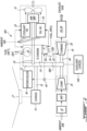
- FIG. 2 shows an exemplary schematic representation of first engine system 18A of power plant 12 shown in FIG. 1 .
- first engine system 18A and second engine system 18B of power plant 12 may be of substantially identical construction, and may have substantially identical power output ratings.
- first engine system 18A and second engine system 18B may be of different constructions and may have different power output ratings.
- First engine system 18A may include internal combustion (IC) engine 24 using intermittent combustion during operation.
- IC engine 24 may be of a type other than a gas turbine engine.
- IC engine 24 may be of a type where the exhaust gas from IC engine 24 produces no significant thrust for propelling aircraft 10.
- Such IC engine 24 with intermittent combustion may be a reciprocating engine such as piston engine, or a pistonless rotary (e.g., Wankel) engine where heat is added at substantially constant volume in the thermodynamic cycle.
- IC engine 24 may include a Wankel engine using an eccentric rotary design to convert pressure into rotating motion.
- IC engine 24 may of a type described in US Patent No.
- IC engine 24 may operate on a mixture of relatively heavy fuel (e.g. diesel, kerosene (jet fuel), equivalent biofuel) and air.
- relatively heavy fuel e.g. diesel, kerosene (jet fuel), equivalent biofuel
- IC engine 24 may drive engine output shaft 26, which may be drivingly connected to load 14 to transfer motive power from IC engine 24 to load 14.
- Load 14 may include main rotor 27 of a helicopter.
- IC engine 24 may include combustion chamber 28 including one or more fuel injectors 30A (referred hereinafter in the singular) for delivering fuel WF1 into combustion chamber 28.
- Fuel WF1 may be mixed with air in combustion chamber 28 and ignited to generate a flow of first exhaust gas.
- the flow of first exhaust gas may be discharged from exhaust outlet 32 of IC engine 24.
- Exhaust outlet 32 may be an outlet of combustion chamber 28.
- IC engine 24 may be turbocharged by way of optional turbocharger 34.
- Turbocharger 34 may include compressor 36 and turbine 38 which may be drivingly interconnected via turbine shaft 40 so that compressor 36 may be driven by turbine 38.
- Compressor 36 and turbine 38 may each be a single-stage device or a multiple-stage device with a single shaft, or split on multiple independent shafts in parallel or in series, and may be a centrifugal, axial or mixed device.
- Compressor 36 of turbocharger 34 may receive (e.g., ambient) air and compress the air to be supplied as combustion air to IC engine 24.
- the ambient air may be received via ambient air inlet 42 and optional variable-orientation guide vanes 44A that may guide the flow of ambient air being delivered to compressor 36 to promote a desirable operation of compressor 36 at different operating conditions.
- the compressed air from compressor 36 may be passed through intercooler 46.
- Intercooler 46 may include a suitable (e.g., air to air) heat exchanger that may facilitate heat transfer from the compressed air to ambient air or to another fluid to remove some of the heat added to the compressed air during compression, and promote a desirable operation of IC engine 24.
- Turbine shaft 40 of turbocharger 34 may be drivingly connected to load 14 via output shaft 16, gearbox 22, and optional variable speed transmission 48A so that motive power extracted by turbine 38 may be transferred to load 14.
- Variable speed transmission 48A may permit motive power to be transmitted from turbine shaft 40 to load 14 at varying relative rotational speeds between turbine shaft 40 and load 14.
- variable speed transmission 48A may be a continuously variable transmission (CVT) that can change seamlessly and continuously through a range of gear ratios.
- Turbine shaft 40 of turbocharger 34 may optionally be drivingly connected to one or more auxiliary loads 14A, directly, via a clutch, via a gearbox, and/or via another or the same variable speed transmission 48A, so that motive power may be transferred from turbine 38 to auxiliary load(s) 14A.
- Such auxiliary load(s) 14A may include an electric generator, an oil pump of a lubrication system, and/or a hydraulic pump of a hydraulic system for example.
- IC engine 24 may be liquid cooled using suitable coolant fluid (e.g., a solution of a suitable organic chemical such as ethylene glycol, diethylene glycol, or propylene glycol in water).
- suitable coolant fluid e.g., a solution of a suitable organic chemical such as ethylene glycol, diethylene glycol, or propylene glycol in water.
- heat generated by IC engine 24 may be transferred to a suitable coolant fluid (e.g., liquid) circulating into IC engine 24, and carried out of IC engine 24 by the coolant fluid. Heat may then be rejected by the coolant fluid via coolant heat exchanger 50 (referred hereinafter as "coolant HX 50"), which may promote heat transfer from the coolant fluid to ambient air.
- the ambient air may be driven through coolant HX 50 by fan 52.
- Fan 52 may be configured and positioned to pull or push the ambient air through coolant HX 50.
- fan 52 may be mechanically driven by engine output shaft 26 either directly or via variable speed transmission 48B which may be a CVT for example.
- fan 52 could instead be driven by other means such as an electric motor or a hydraulic motor for example.
- variable-orientation guide vanes 44B may guide the flow of ambient air being delivered to fan 52 to promote a desirable operation of fan 52 at different operating conditions.
- Some heat generated by IC engine 24 may also be transferred to a suitable lubricating fluid (e.g., oil) circulating into IC engine 24, and carried out of IC engine 24 by the lubricating fluid. Heat may then be rejected by the lubricating fluid via oil heat exchanger 54 (referred hereinafter as "oil HX 54"), which may promote heat transfer from the lubricating fluid to ambient air.
- oil HX 54 oil heat exchanger 54
- the ambient air may be driven through oil HX 54 by fan 52 or another fan.
- Fan 52 may be configured and positioned to pull or push the ambient air through oil HX 54.
- First engine system 18A may include combustor 56 operatively disposed between IC engine 24 and turbine 38 of turbocharger 34.
- Combustor 56 may be operated as an inter-burner as needed when supplemental power output capacity from first engine system 18A is required.
- combustor 56 may be inactive and the first exhaust gas discharged from exhaust outlet 32 of IC engine 24 may be directed to turbine 38 and may drive turbine 38.
- turbine 38 may extract motive power from the first exhaust gas discharged from exhaust outlet 32.
- the first exhaust gas discharged from exhaust outlet 32 may pass through combustor 56 while combustor 56 is inactive (i.e., unlit).
- IC engine 24 may provide a pulsating exhaust gas flow out of exhaust outlet 32.
- Combustor 56 may include combustor inlet 58 in fluid communication with exhaust outlet 32 of IC engine 24 to receive the flow of first exhaust gas from IC engine 24 into combustor 56.
- Combustor 56 may be disposed outside and downstream of combustion chamber 28 of IC engine 24.
- Combustor 56 may be disposed outside of IC engine 24.
- the air-fuel mixture that is burned in combustion chamber 28 of IC engine 24 may have an air-fuel ratio that is higher than stoichiometric (i.e., lean), and the resulting first exhaust gas discharged from exhaust outlet 32 may contain sufficient oxygen to sustain subsequent combustion in combustor 56 in order to generate the supplemental power output capacity of first engine system 18A.
- first engine system 18A may include one or more valves 60 that are operatively disposed to permit compressed air produced by compressor 36 to be selectively injected into the first exhaust gas discharged from exhaust outlet 32.
- Valve(s) 60 may include a three-way valve configured to permit a portion of the compressed air from compressor 36 to be delivered to intercooler 46, and another portion of the compressed air from compressor 36 to be injected into the first exhaust gas downstream of exhaust outlet 32.
- the additional air may be added to the first exhaust gas if required to facilitate subsequent combustion in combustor 56, or to help/facilitate the (e.g., surge free) operability of compressor 36 under certain operating conditions.
- Combustor 56 may include one or more fuel injectors 30B for injecting fuel into combustor 56 where the fuel is mixed with the first exhaust gas discharged from exhaust outlet 32, and ignited for generating a flow of second exhaust gas containing a greater amount of energy.
- the number and configuration of fuel injector(s) 30B may be selected to provide adequate priming and fuel delivery to combustor 56 in order to provide an acceptable activation/response time in case of an emergency situation for example.
- the temperature of first exhaust gas entering combustor 56 may be sufficiently high so that ignition of the fuel injected into combustor 56 via injector(s) 30B may be automatic.
- combustor 56 may include one or more igniters to facilitate the ignition of combustor 56.
- Combustor 56 may include combustor outlet 62 for discharging the flow of second exhaust gas from combustor 56.
- Turbine 38 may be in fluid communication with combustor outlet 62 and be driven by the flow of second exhaust gas. In other words, turbine 38 may convert energy from the flow of second exhaust gas into motive power that can be used to drive compressor 36, load 14 and/or auxiliary load(s) 14A. The flow of second exhaust gas flowing through turbine 38 may then be discharged from first engine system 18A via exhaust duct 64 and muffler 66.
- FIG. 3 is a flowchart of an exemplary method 100 of driving a load (e.g., load 14 and/or auxiliary load 14A) onboard aircraft 10.
- Method 100 may be performed using first engine system 18A and/or using second engine system 18B described herein or using other engine system(s). Aspects of power plant 12 and of first engine system 18A may be incorporated into method 100. Aspects of method 100 may be combined with other steps or actions disclosed herein.
- method 100 may include:
- Method 100 may include transferring motive power from turbine 38 to compressor 36 of turbocharger 34 to drive compressor 36.
- Compressor 36 may compress ambient air and the compressed air may be delivered to IC engine 24 and used as compressed air by IC engine 24.
- load 14 may include main rotor 27 of a helicopter.
- combustor 56 may be used during momentary peak power operation only when the supplemental power output capacity beyond that of IC engine 24 is required from first engine system 18A or from second engine system 18B. Such momentary peak power operation may be performed during a takeoff phase of flight of aircraft 10, and/or during an emergency situation for example. Accordingly, method 100 may, after the momentary peak power operation, include:
- a suitable forward or reverse fuel purging procedure may be implemented in order to clear fuel injector(s) 30B of residual fuel WF2.
- compressed air may be directed into fuel injector(s) 30B in order to push the residual fuel WF2 into combustor 56 after the delivery of fuel WF2 to fuel injector(s) 30B has been stopped.
- a reverse purging procedure may be implemented to withdraw residual fuel WF2 from fuel injector(s) 30B and collect the residual fuel WF2 into a suitable reservoir.
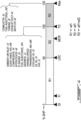
- FIG. 4 is a graphical representation of different operating regimes of first engine system 18A together with exemplary sizing requirements for elements of first engine system 18A.
- First engine system 18A may be arranged in a turboshaft setup in a twin-engine helicopter.
- First engine system 18A may be designed for a 130% maximum shaft horsepower (SHP) capability where 0% SHP corresponds to a ground idle (GI) power rating, 60% SHP corresponds to a long range cruise (LRC) power rating, and 100% SHP corresponds to the required takeoff (TO) power rating.
- SHP 130% maximum shaft horsepower
- GI ground idle
- 60% SHP corresponds to a long range cruise
- TO takeoff
- FIG. 4 also shows a location of a flight idle (FI) power rating disposed between GI and LRC.
- FIG. 4 also shows a location of a maximum cruise (MCR) power rating disposed between LRC and TO.
- FI flight idle
- MCR maximum cruise
- FIG. 4 shows three operating regimes of first engine system 18A disposed along a power output scale expressed in % SHP extending from 0% to 130%.
- First regime R1 may correspond to a relatively low power/transient operation where the operability (e.g., no compressor surge) may be a key objective and specific fuel consumption (SFC) may be less important.
- the SHP delivered to load 14 may be provided by IC engine 24 with fuel WF1 being delivered to combustion chamber 28, and with combustor 56 being inactive where fuel WF2 is not being delivered to combustor 56.
- Second regime R2 may correspond to normal day-to-day operation where all engines of aircraft 10 are operative. Obtaining a favorable SFC may be a key objective in second regime R2.
- the SHP delivered to load 14 may be provided by IC engine 24 with fuel WF1 being delivered to combustion chamber 28, and with combustor 56 being inactive where fuel WF2 is not being delivered to combustor 56.
- Third regime R3 may correspond to an emergency condition such as when second engine system 18B is inoperative (i.e., "one engine inoperative” or "OEI") for example, and first engine system 18A must provide supplemental power output.
- obtaining the required SHP output from first engine system 18A may be a key objective and SFC may be less important.
- the SHP delivered to load 14 may be provided by IC engine 24 with fuel WF1 being delivered to combustion chamber 28, and also with combustor 56 being active where fuel WF2 is being delivered to combustor 56 as well.
- the supplemental power output required from first engine system 18A may be beyond what IC engine 24 alone is capable of providing. Accordingly, the supplemental power output may be provided by way of combustor 56.
- FIG. 4 also indicates sizing requirements for various components of first engine system 18A.
- the architecture of first engine system 18A may make the supplemental power output capacity available without incurring significant size or weight penalty for first engine system 18A.
- a maximum power output capacity of first aircraft engine system 18A may be greater than a maximum output power capacity of IC engine 24.
- the supplemental power capacity may be provided separately from IC engine 24 so that the power output capacity of IC engine 24 may be left intact. Consequently, the bearing loads of IC engine 24, and the size and weight of the (e.g., liquid-cooling, oil cooling) systems of IC engine 24 also may not need to be increased.
- IC engine 24 and its associated systems may be designed and sized to function effectively and efficiently in first regime R1 and second regime R2 between 0% SHP and 100% SHP.
- First engine system 18A may nevertheless provide the supplemental power output capacity using combustor 56 when required. Accordingly, as shown in FIG. 4 , several components of engine system 18A may only need to be sized for 100% SHP (i.e., TO rating) while only some components of engine system 18A may required to be sized for 130% SHP.
- variable speed transmission 48A and gearbox 22 may be designed for 100% SHP but may also have the capacity to momentarily operate at 130% SHP with some design adjustments (if required).
- FIG. 5 is another graphical representation of different operating regimes of first engine system 18A together with exemplary sizing requirements for elements of first engine system 18A.
- First engine system 18A may be arranged in a turboshaft setup in a twin-engine helicopter.
- First engine system 18A may be designed for a 115% maximum SHP capability where 0% SHP corresponds to a GI power rating, 60% SHP corresponds to a LRC power rating, and 100% SHP corresponds to the required TO power rating.
- FIG. 5 also shows a location of a FI power rating between GI and LRC.
- FIG. 5 also shows a location of a MCR power rating at 85% SHP.
- FIG. 5 shows three operating regimes of first engine system 18A disposed along a power range scale expressed in % SHP extending from 0% to 115%.
- First regime R1 may correspond to a relatively low power/transient operation where the operability (e.g., no compressor surge) may be a key objective and specific fuel consumption (SFC) may be less important.
- the SHP delivered to load 14 may be provided by IC engine 24 with fuel WF1 being delivered to combustion chamber 28, and with combustor 56 being inactive where fuel WF2 is not being delivered to combustor 56.
- Second regime R2 may correspond to normal day-to-day operation (other than TO) where all engines of aircraft 10 are operative and obtaining a favorable SFC may be a key objective.
- the SHP delivered to load 14 may be provided by IC engine 24 with fuel WF1 being delivered to combustion chamber 28, and with combustor 56 being inactive where fuel WF2 is not being delivered to combustor 56.
- Third regime R3 may include the TO rating (100% SHP) and also an emergency condition beyond the TO rating such as when second engine system 18B is inoperative (i.e., "one engine inoperative” or "OEI") for example, and first engine system 18A must provide supplemental power output.
- obtaining the required SHP output from first engine system 18A may be a key objective and SFC may be less important.
- the SHP delivered to load 14 may be provided by IC engine 24 with fuel WF1 being delivered to combustion chamber 28, and with combustor 56 being active where fuel WF2 is being delivered to combustor 56.
- the supplemental power output required from first engine system 18A between 85%-115% SHP may be beyond what IC engine 24 alone is normally capable of providing. Accordingly, the supplemental power output may be provided by way of combustor 56.
- the engine configuration represented in FIG. 5 may provide a lower maximum SHP but may offer better SFC when operating at LRC (-60% SHP) with a smaller compressor 36 and smaller fuel injector(s) 30A, both designed for MCR rating of 85% SHP.
- the engine configuration represented in FIG. 4 may be designed for a higher maximum SHP (i.e., +30% over the TO rating), with relatively good LRC SFC.
- the engine configuration represented in FIG. 5 may be designed for better LRC SFC, with lower maximum SHP (i.e., +15% over the TO rating).
- FIG. 5 also indicates sizing requirements for various components of first engine system 18A.
- the architecture of first engine system 18A may make the supplemental power output capacity available without incurring significant size or weight penalty for first engine system 18A.
- the supplemental power capacity may be provided separately from IC engine 24 so that the power output capacity of IC engine 24 need not be increased. Consequently, IC engine 24 and its associated systems may be designed and sized to function effectively and efficiently in first regime R1 and second regime R2 between 0% SHP and 85% SHP.
- First engine system 18A may nevertheless provide the supplemental power output capacity using combustor 56 when required. Accordingly, as shown in FIG. 5 , some components may only need to be sized for 85% SHP (i.e., MCR rating), some components may need to be sized for 100% SHP (i.e., TO rating), and some components may require to be sized for 115% SHP.
- variable speed transmission 48A and gearbox 22 may be designed mainly for 100% SHP but may also have the capacity to momentarily operate at 115% SHP with some design adjustments (if required).
- components and systems associated with IC engine 24 may be designed mainly for 85% SHP but may also have the capacity to momentarily operate at 100% SHP to handle the TO phase with some design adjustments (if required).
- combustor 56 may be used between 85 and 115% SHP.
- Fuel Injector(s) 30A for injecting WF1 into IC engine 24 may be sized/optimized to cause IC engine 24 to deliver 85% SHP. The extra output power beyond 85% SHP may then come solely from the use of fuel injector(s) 30B and combustor 56. Some components such as IC engine 24, gearbox 22, variable speed transmission 48A, and optionally exhaust duct 64, and muffler 66 may still need to be sized for 100% SHP to provide an adequate durability to permit IC engine 24 to be operated continuously at 85% SHP (MCR) for example.
- MCR 85% SHP
Landscapes
- Engineering & Computer Science (AREA)
- Chemical & Material Sciences (AREA)
- Combustion & Propulsion (AREA)
- Mechanical Engineering (AREA)
- General Engineering & Computer Science (AREA)
- Aviation & Aerospace Engineering (AREA)
- Chemical Kinetics & Catalysis (AREA)
- General Chemical & Material Sciences (AREA)
- Supercharger (AREA)
- Engine Equipment That Uses Special Cycles (AREA)
Abstract
Description
- The disclosure (invention) relates generally to aircraft, and more particularly to aircraft power plants.
- It is desirable for aircraft engines to operate in an energy efficient manner to promote reduced fuel consumption and operating costs. In aircraft applications, the power output capacity of an engine relative to the weight of the engine is an important factor that can affect the overall efficiency of the aircraft since the weight of the engine must be carried by the aircraft during flight. Aircraft engines can be required to have a maximum power output rating that can be produced during short-term (i.e., momentary) peak power operation in situations such as during take-off or during emergency situations. Even though, the long-term continuous operation of the aircraft engines during a cruise phase of flight, for example, can be well below such maximum power output rating, the maximum power output rating can necessitate increased size and weight of aircraft engines. Improvement is desirable.
- In one aspect, the invention describes an aircraft power plant comprising: an internal combustion (IC) engine using intermittent combustion during operation, the IC engine being drivingly connected to a load to transfer motive power from the IC engine to the load, the IC engine having an exhaust outlet for discharging a flow of first exhaust gas; a combustor including: a combustor inlet in fluid communication with the exhaust outlet of the IC engine to receive the flow of first exhaust gas from the IC engine into the combustor; a fuel injector for injecting fuel into the combustor in which the fuel is mixed with the first exhaust gas and ignited to generate a flow of second exhaust gas; and a combustor outlet for discharging the flow of second exhaust gas; and a turbocharger associated with the IC engine, the turbocharger including: a turbine in fluid communication with the combustor outlet and driven by the flow of second exhaust gas, the turbine being drivingly connected to the load to transfer motive power from the turbine to the load; and a compressor drivingly connected to the turbine and driven by the turbine to compress combustion air for the IC engine.
- In another aspect, the disclosure describes an aircraft engine system comprising: a Wankel engine drivingly connected to a load to transfer motive power from the Wankel engine to the load, the Wankel engine having an exhaust outlet for discharging a flow of exhaust gas from the Wankel engine; a turbine in fluid communication with the exhaust outlet of the Wankel engine and driven by the flow of exhaust gas, the turbine being drivingly connected to the load to transfer motive power from the turbine to the load; and an inter-burner operatively disposed between the Wankel engine and the turbine to add energy to the flow of exhaust gas between the Wankel engine and the turbine.
- In a further aspect, the disclosure describes a method of driving a load onboard an aircraft. The method comprises: transferring motive power from an internal combustion (IC) engine to the load, the IC engine using intermittent combustion during operation; discharging a flow of first exhaust gas from the IC engine when transferring motive power from the IC engine to the load; receiving the flow of first exhaust gas from the IC engine into a combustor; mixing fuel with the first exhaust gas in the combustor and igniting the fuel to generate a flow of second exhaust gas; receiving the flow of second exhaust gas at a turbine and driving the turbine with the flow of second exhaust gas from the combustor; and transferring motive power from the turbine to the load.
- Further details of these and other aspects of the subject matter of this application will be apparent from the detailed description included below and the drawings.
- Reference is now made to the accompanying drawings, in which:
-
FIG. 1 schematically shows an aircraft including a twin-engine power plant as described herein; -
FIG. 2 shows an exemplary schematic representation of an engine system of the aircraft power plant ofFIG. 1 ; -
FIG. 3 is a flowchart of an exemplary method of driving a load onboard an aircraft; -
FIG. 4 is a graphical representation of different operating regimes of the engine system ofFIG. 2 together with exemplary sizing requirements for elements of the engine system; and -
FIG. 5 is another graphical representation of different operating regimes of the engine system ofFIG. 2 together with other exemplary sizing requirements for elements of the engine system. - The present disclosure describes aircraft power plants, engine systems, and associated methods. In various embodiments, aircraft power plants described herein may be configured to provide momentary supplemental power output without necessitating significant size or weight increase of the aircraft power plants. For example, the aircraft power plants described herein may include an internal combustion (IC) engine with one or more associated systems such as a liquid cooling system, an oil cooling system, and bearings that are sized according to a power output capacity of the IC engine. In some embodiments, the momentary supplemental power output capacity of the power plant may be provided via a combustor (i.e., inter-burner) in which fuel may be mixed with exhaust gas from the IC engine, and the mixture may be ignited to generate supplemental power that may be extracted via a turbine and used when needed. In some embodiments, the combustor may provide momentary supplemental power output capacity for the power plant as a whole without increasing the power output capacity of the IC engine, the size and weight the (e.g., liquid cooling) systems of the IC engine, and bearings of the IC engine. Accordingly, the IC engine and its associated systems may be sized and designed for efficient operation during long-term continuous operation of the aircraft power plant during a cruise phase of flight for example, and the supplemental power output capacity may be provided by selectively activating the combustor when needed.
- Aspects of various embodiments are described through reference to the drawings.
- The term "connected" may include both direct connection (where two elements contact each other) and indirect connection (where at least one additional element is located between the two elements).
- The term "substantially" as used herein may be applied to modify any quantitative representation which could permissibly vary without resulting in a change in the basic function to which it is related.
-
FIG. 1 schematically showsaircraft 10 including aircraft power plant 12 (referred hereinafter as "power plant 12") as described herein. In various embodiments,aircraft 10 may be a manned aircraft or an unmanned aircraft (e.g., drone). For example,aircraft 10 may be a corporate, private, fixed-wing, rotary-wing (e.g., helicopter) or commercial passenger aircraft. In some embodiments,power plant 12 may be part of a propulsion system ofaircraft 10.Power plant 12 may be drivingly connected to one or more loads 14 (referred hereinafter in the singular) viaoutput shaft 16. In some embodiments,load 14 may include a propeller configured to generate thrust and/or lift foraircraft 10. In some embodiments,load 14 may include a rotary wing (e.g., main rotor) of a helicopter or other type of rotorcraft. In some embodiments,power plant 12 may provide energy for propellingaircraft 10, and optionally also provide energy to drive loads for functions other than propulsion such as driving a compressor supplying compressed air to pneumatic loads, driving an electric generator supplying electric energy to electric loads, driving an oil pump supplying oil to lubrication loads, and/or driving a hydraulic pump supplying pressurized hydraulic fluid to hydraulic actuators. Alternatively,power plant 12 may be an auxiliary power unit (APU) ofaircraft 10 and may provide energy exclusively for functions other than propulsion ofaircraft 10. -
Aircraft power plant 12 may include asingle engine system 18A, or a plurality ofengine systems power plant 12 may be a multi-engine system (e.g., twin-pack power plant) includingfirst engine system 18A andsecond engine system 18B. Control of first andsecond engine systems engine systems aircraft 10 to reduce an overall fuel burn for example. Controller(s) 20 may include a first controller for controllingfirst engine system 18A and a second controller for controllingsecond engine system 18B. In some embodiments, asingle controller 20 may be used for controllingfirst engine system 18A andsecond engine 18B. -
Power plant 12 may be operable so thatengine systems aircraft 10. However there may be other reasons whyengine systems engine systems Power plant 12 may be used in aircraft applications but may also be suitable for marine, industrial and/or other ground operations. - In use,
first engine system 18A may operate in the active mode whilesecond engine system 18B may operate in the standby mode. During this asymmetric operation, if the helicopter needs a power increase (expected or otherwise),second engine system 18B may be required to provide more power relative to the low power conditions of the standby mode, and possibly return immediately to a high- or full-power condition. This may occur, for example, during take-off or in an emergency condition where the "active"first engine system 18A loses power. Even absent an emergency, it may be desirable to repower the standby engine to exit the asymmetric mode in some situations. - First and
second engine systems gearbox 22, which may be of a speed-changing (e.g., reducing) type. For example,gear box 22 may have a plurality of inputs to receive motive power (mechanical energy) from respective shafts ofengine systems Gear box 22 may be configured to direct at least some of the combined motive power from the plurality ofengine systems common output shaft 16 fordriving load 14 at a suitable operating (e.g., rotational) speed. -
FIG. 2 shows an exemplary schematic representation offirst engine system 18A ofpower plant 12 shown inFIG. 1 . In some embodiments,first engine system 18A andsecond engine system 18B ofpower plant 12 may be of substantially identical construction, and may have substantially identical power output ratings. Alternatively, in some embodiments,first engine system 18A andsecond engine system 18B may be of different constructions and may have different power output ratings. -
First engine system 18A may include internal combustion (IC)engine 24 using intermittent combustion during operation.IC engine 24 may be of a type other than a gas turbine engine. For example,IC engine 24 may be of a type where the exhaust gas fromIC engine 24 produces no significant thrust for propellingaircraft 10.Such IC engine 24 with intermittent combustion may be a reciprocating engine such as piston engine, or a pistonless rotary (e.g., Wankel) engine where heat is added at substantially constant volume in the thermodynamic cycle. In some embodiments,IC engine 24 may include a Wankel engine using an eccentric rotary design to convert pressure into rotating motion. In some embodiments,IC engine 24 may of a type described inUS Patent No. 10,107,195 IC engine 24 may operate on a mixture of relatively heavy fuel (e.g. diesel, kerosene (jet fuel), equivalent biofuel) and air. -
IC engine 24 may driveengine output shaft 26, which may be drivingly connected to load 14 to transfer motive power fromIC engine 24 to load 14.Load 14 may includemain rotor 27 of a helicopter.IC engine 24 may includecombustion chamber 28 including one ormore fuel injectors 30A (referred hereinafter in the singular) for delivering fuel WF1 intocombustion chamber 28. Fuel WF1 may be mixed with air incombustion chamber 28 and ignited to generate a flow of first exhaust gas. The flow of first exhaust gas may be discharged fromexhaust outlet 32 ofIC engine 24.Exhaust outlet 32 may be an outlet ofcombustion chamber 28. - In some embodiments,
IC engine 24 may be turbocharged by way ofoptional turbocharger 34.Turbocharger 34 may includecompressor 36 andturbine 38 which may be drivingly interconnected viaturbine shaft 40 so thatcompressor 36 may be driven byturbine 38.Compressor 36 andturbine 38 may each be a single-stage device or a multiple-stage device with a single shaft, or split on multiple independent shafts in parallel or in series, and may be a centrifugal, axial or mixed device.Compressor 36 ofturbocharger 34 may receive (e.g., ambient) air and compress the air to be supplied as combustion air toIC engine 24. The ambient air may be received viaambient air inlet 42 and optional variable-orientation guide vanes 44A that may guide the flow of ambient air being delivered tocompressor 36 to promote a desirable operation ofcompressor 36 at different operating conditions. In some embodiments, the compressed air fromcompressor 36 may be passed through intercooler 46. Intercooler 46 may include a suitable (e.g., air to air) heat exchanger that may facilitate heat transfer from the compressed air to ambient air or to another fluid to remove some of the heat added to the compressed air during compression, and promote a desirable operation ofIC engine 24. -
Turbine shaft 40 ofturbocharger 34 may be drivingly connected to load 14 viaoutput shaft 16,gearbox 22, and optionalvariable speed transmission 48A so that motive power extracted byturbine 38 may be transferred to load 14.Variable speed transmission 48A, may permit motive power to be transmitted fromturbine shaft 40 to load 14 at varying relative rotational speeds betweenturbine shaft 40 andload 14. In some embodiments,variable speed transmission 48A may be a continuously variable transmission (CVT) that can change seamlessly and continuously through a range of gear ratios.Turbine shaft 40 ofturbocharger 34 may optionally be drivingly connected to one or moreauxiliary loads 14A, directly, via a clutch, via a gearbox, and/or via another or the samevariable speed transmission 48A, so that motive power may be transferred fromturbine 38 to auxiliary load(s) 14A. Such auxiliary load(s) 14A may include an electric generator, an oil pump of a lubrication system, and/or a hydraulic pump of a hydraulic system for example. - In some embodiments,
IC engine 24 may be liquid cooled using suitable coolant fluid (e.g., a solution of a suitable organic chemical such as ethylene glycol, diethylene glycol, or propylene glycol in water). For example, heat generated byIC engine 24 may be transferred to a suitable coolant fluid (e.g., liquid) circulating intoIC engine 24, and carried out ofIC engine 24 by the coolant fluid. Heat may then be rejected by the coolant fluid via coolant heat exchanger 50 (referred hereinafter as "coolant HX 50"), which may promote heat transfer from the coolant fluid to ambient air. The ambient air may be driven throughcoolant HX 50 byfan 52.Fan 52 may be configured and positioned to pull or push the ambient air throughcoolant HX 50. In some embodiments,fan 52 may be mechanically driven byengine output shaft 26 either directly or viavariable speed transmission 48B which may be a CVT for example. However,fan 52 could instead be driven by other means such as an electric motor or a hydraulic motor for example. In some embodiments, variable-orientation guide vanes 44B may guide the flow of ambient air being delivered to fan 52 to promote a desirable operation offan 52 at different operating conditions. - Some heat generated by
IC engine 24 may also be transferred to a suitable lubricating fluid (e.g., oil) circulating intoIC engine 24, and carried out ofIC engine 24 by the lubricating fluid. Heat may then be rejected by the lubricating fluid via oil heat exchanger 54 (referred hereinafter as "oil HX 54"), which may promote heat transfer from the lubricating fluid to ambient air. The ambient air may be driven throughoil HX 54 byfan 52 or another fan.Fan 52 may be configured and positioned to pull or push the ambient air throughoil HX 54. -
First engine system 18A may includecombustor 56 operatively disposed betweenIC engine 24 andturbine 38 ofturbocharger 34.Combustor 56 may be operated as an inter-burner as needed when supplemental power output capacity fromfirst engine system 18A is required. When the supplemental power output capacity fromfirst engine system 18A is not required,combustor 56 may be inactive and the first exhaust gas discharged fromexhaust outlet 32 ofIC engine 24 may be directed toturbine 38 and may driveturbine 38. In other words,turbine 38 may extract motive power from the first exhaust gas discharged fromexhaust outlet 32. During this mode of operation, the first exhaust gas discharged fromexhaust outlet 32 may pass throughcombustor 56 whilecombustor 56 is inactive (i.e., unlit). In some embodiments,IC engine 24 may provide a pulsating exhaust gas flow out ofexhaust outlet 32. -
Combustor 56 may includecombustor inlet 58 in fluid communication withexhaust outlet 32 ofIC engine 24 to receive the flow of first exhaust gas fromIC engine 24 intocombustor 56.Combustor 56 may be disposed outside and downstream ofcombustion chamber 28 ofIC engine 24.Combustor 56 may be disposed outside ofIC engine 24. In some operating conditions, the air-fuel mixture that is burned incombustion chamber 28 ofIC engine 24 may have an air-fuel ratio that is higher than stoichiometric (i.e., lean), and the resulting first exhaust gas discharged fromexhaust outlet 32 may contain sufficient oxygen to sustain subsequent combustion incombustor 56 in order to generate the supplemental power output capacity offirst engine system 18A. In some embodiments,first engine system 18A may include one ormore valves 60 that are operatively disposed to permit compressed air produced bycompressor 36 to be selectively injected into the first exhaust gas discharged fromexhaust outlet 32. Valve(s) 60 may include a three-way valve configured to permit a portion of the compressed air fromcompressor 36 to be delivered to intercooler 46, and another portion of the compressed air fromcompressor 36 to be injected into the first exhaust gas downstream ofexhaust outlet 32. In some situations, the additional air may be added to the first exhaust gas if required to facilitate subsequent combustion incombustor 56, or to help/facilitate the (e.g., surge free) operability ofcompressor 36 under certain operating conditions. -
Combustor 56 may include one ormore fuel injectors 30B for injecting fuel intocombustor 56 where the fuel is mixed with the first exhaust gas discharged fromexhaust outlet 32, and ignited for generating a flow of second exhaust gas containing a greater amount of energy. The number and configuration of fuel injector(s) 30B may be selected to provide adequate priming and fuel delivery tocombustor 56 in order to provide an acceptable activation/response time in case of an emergency situation for example. In some embodiments, the temperature of first exhaustgas entering combustor 56 may be sufficiently high so that ignition of the fuel injected intocombustor 56 via injector(s) 30B may be automatic. In some embodiments,combustor 56 may include one or more igniters to facilitate the ignition ofcombustor 56. -
Combustor 56 may includecombustor outlet 62 for discharging the flow of second exhaust gas fromcombustor 56.Turbine 38 may be in fluid communication withcombustor outlet 62 and be driven by the flow of second exhaust gas. In other words,turbine 38 may convert energy from the flow of second exhaust gas into motive power that can be used to drivecompressor 36,load 14 and/or auxiliary load(s) 14A. The flow of second exhaust gas flowing throughturbine 38 may then be discharged fromfirst engine system 18A via exhaust duct 64 and muffler 66. -
FIG. 3 is a flowchart of anexemplary method 100 of driving a load (e.g., load 14 and/orauxiliary load 14A)onboard aircraft 10.Method 100 may be performed usingfirst engine system 18A and/or usingsecond engine system 18B described herein or using other engine system(s). Aspects ofpower plant 12 and offirst engine system 18A may be incorporated intomethod 100. Aspects ofmethod 100 may be combined with other steps or actions disclosed herein. In various embodiments,method 100 may include: - transferring motive power from
IC engine 24 to load 14 (block 102); - discharging a flow of first exhaust gas from
IC engine 24 when transferring motive power fromIC engine 24 to load 14 (block 104); - receiving the flow of first exhaust gas from
IC engine 24 into combustor 56 (block 106); - mixing fuel WF2 with the first exhaust gas in
combustor 56 and igniting the fuel WF2 to generate a flow of second exhaust gas (block 108); - receiving the flow of second exhaust gas at
turbine 38 and drivingturbine 38 with the flow of second exhaust gas from combustor 56 (block 110); and - transferring motive power from the turbine to the load (block 112).
-
Method 100 may include transferring motive power fromturbine 38 tocompressor 36 ofturbocharger 34 to drivecompressor 36.Compressor 36 may compress ambient air and the compressed air may be delivered toIC engine 24 and used as compressed air byIC engine 24. - In some embodiments of
method 100, load 14 may includemain rotor 27 of a helicopter. - In some embodiments of
method 100,combustor 56 may be used during momentary peak power operation only when the supplemental power output capacity beyond that ofIC engine 24 is required fromfirst engine system 18A or fromsecond engine system 18B. Such momentary peak power operation may be performed during a takeoff phase of flight ofaircraft 10, and/or during an emergency situation for example. Accordingly,method 100 may, after the momentary peak power operation, include: - ceasing to mix fuel WF2 with the first exhaust gas and igniting the fuel WF2 in
combustor 56 to generate a flow of second exhaust gas; - receiving the flow of first exhaust gas at
turbine 38 and drivingturbine 38 with the flow of first exhaust gas; and - transferring motive power from
turbine 38 to load 14 and/or tocompressor 36 ofturbocharger 34 associated withIC engine 24. - When ceasing to mix fuel WF2 with the first exhaust gas inside of
combustor 56, fuel flow tocombustor 56 via fuel injector(s) 30B may be stopped. The flow of first exhaust gas may flow throughcombustor 56 whilecombustor 56 is inactive. In order to prevent coking of residual fuel WF2 inside of fuel injector(s) 30B, a suitable forward or reverse fuel purging procedure may be implemented in order to clear fuel injector(s) 30B of residual fuel WF2. For example, compressed air may be directed into fuel injector(s) 30B in order to push the residual fuel WF2 intocombustor 56 after the delivery of fuel WF2 to fuel injector(s) 30B has been stopped. Alternatively, a reverse purging procedure may be implemented to withdraw residual fuel WF2 from fuel injector(s) 30B and collect the residual fuel WF2 into a suitable reservoir. -
FIG. 4 is a graphical representation of different operating regimes offirst engine system 18A together with exemplary sizing requirements for elements offirst engine system 18A.First engine system 18A may be arranged in a turboshaft setup in a twin-engine helicopter.First engine system 18A may be designed for a 130% maximum shaft horsepower (SHP) capability where 0% SHP corresponds to a ground idle (GI) power rating, 60% SHP corresponds to a long range cruise (LRC) power rating, and 100% SHP corresponds to the required takeoff (TO) power rating.FIG. 4 also shows a location of a flight idle (FI) power rating disposed between GI and LRC.FIG. 4 also shows a location of a maximum cruise (MCR) power rating disposed between LRC and TO. -
FIG. 4 shows three operating regimes offirst engine system 18A disposed along a power output scale expressed in % SHP extending from 0% to 130%. First regime R1 may correspond to a relatively low power/transient operation where the operability (e.g., no compressor surge) may be a key objective and specific fuel consumption (SFC) may be less important. During first regime R1, the SHP delivered to load 14 may be provided byIC engine 24 with fuel WF1 being delivered tocombustion chamber 28, and withcombustor 56 being inactive where fuel WF2 is not being delivered tocombustor 56. - Second regime R2 may correspond to normal day-to-day operation where all engines of
aircraft 10 are operative. Obtaining a favorable SFC may be a key objective in second regime R2. During second regime R2, the SHP delivered to load 14 may be provided byIC engine 24 with fuel WF1 being delivered tocombustion chamber 28, and withcombustor 56 being inactive where fuel WF2 is not being delivered tocombustor 56. - Third regime R3 may correspond to an emergency condition such as when
second engine system 18B is inoperative (i.e., "one engine inoperative" or "OEI") for example, andfirst engine system 18A must provide supplemental power output. During third regime R3, obtaining the required SHP output fromfirst engine system 18A may be a key objective and SFC may be less important. During third regime R3, the SHP delivered to load 14 may be provided byIC engine 24 with fuel WF1 being delivered tocombustion chamber 28, and also withcombustor 56 being active where fuel WF2 is being delivered tocombustor 56 as well. The supplemental power output required fromfirst engine system 18A may be beyond whatIC engine 24 alone is capable of providing. Accordingly, the supplemental power output may be provided by way ofcombustor 56. -
FIG. 4 also indicates sizing requirements for various components offirst engine system 18A. As explained above the architecture offirst engine system 18A may make the supplemental power output capacity available without incurring significant size or weight penalty forfirst engine system 18A. A maximum power output capacity of firstaircraft engine system 18A may be greater than a maximum output power capacity ofIC engine 24. For example, the supplemental power capacity may be provided separately fromIC engine 24 so that the power output capacity ofIC engine 24 may be left intact. Consequently, the bearing loads ofIC engine 24, and the size and weight of the (e.g., liquid-cooling, oil cooling) systems ofIC engine 24 also may not need to be increased. In other words,IC engine 24 and its associated systems may be designed and sized to function effectively and efficiently in first regime R1 and second regime R2 between 0% SHP and 100% SHP.First engine system 18A may nevertheless provide the supplemental power outputcapacity using combustor 56 when required. Accordingly, as shown inFIG. 4 , several components ofengine system 18A may only need to be sized for 100% SHP (i.e., TO rating) while only some components ofengine system 18A may required to be sized for 130% SHP. - The upsizing of muffler 66 may be optional since muffler 66 could potentially be bypassed during the momentary operation in third regime R3.
Variable speed transmission 48A andgearbox 22 may be designed for 100% SHP but may also have the capacity to momentarily operate at 130% SHP with some design adjustments (if required). -
FIG. 5 is another graphical representation of different operating regimes offirst engine system 18A together with exemplary sizing requirements for elements offirst engine system 18A.First engine system 18A may be arranged in a turboshaft setup in a twin-engine helicopter.First engine system 18A may be designed for a 115% maximum SHP capability where 0% SHP corresponds to a GI power rating, 60% SHP corresponds to a LRC power rating, and 100% SHP corresponds to the required TO power rating.FIG. 5 also shows a location of a FI power rating between GI and LRC.FIG. 5 also shows a location of a MCR power rating at 85% SHP. -
FIG. 5 shows three operating regimes offirst engine system 18A disposed along a power range scale expressed in % SHP extending from 0% to 115%. First regime R1 may correspond to a relatively low power/transient operation where the operability (e.g., no compressor surge) may be a key objective and specific fuel consumption (SFC) may be less important. During first regime R1, the SHP delivered to load 14 may be provided byIC engine 24 with fuel WF1 being delivered tocombustion chamber 28, and withcombustor 56 being inactive where fuel WF2 is not being delivered tocombustor 56. - Second regime R2 may correspond to normal day-to-day operation (other than TO) where all engines of
aircraft 10 are operative and obtaining a favorable SFC may be a key objective. During second regime R2, the SHP delivered to load 14 may be provided byIC engine 24 with fuel WF1 being delivered tocombustion chamber 28, and withcombustor 56 being inactive where fuel WF2 is not being delivered tocombustor 56. - Third regime R3 may include the TO rating (100% SHP) and also an emergency condition beyond the TO rating such as when
second engine system 18B is inoperative (i.e., "one engine inoperative" or "OEI") for example, andfirst engine system 18A must provide supplemental power output. During third regime R3, obtaining the required SHP output fromfirst engine system 18A may be a key objective and SFC may be less important. During third regime R3, the SHP delivered to load 14 may be provided byIC engine 24 with fuel WF1 being delivered tocombustion chamber 28, and withcombustor 56 being active where fuel WF2 is being delivered tocombustor 56. The supplemental power output required fromfirst engine system 18A between 85%-115% SHP may be beyond whatIC engine 24 alone is normally capable of providing. Accordingly, the supplemental power output may be provided by way ofcombustor 56. - Compared to
FIG. 4 , the engine configuration represented inFIG. 5 may provide a lower maximum SHP but may offer better SFC when operating at LRC (-60% SHP) with asmaller compressor 36 and smaller fuel injector(s) 30A, both designed for MCR rating of 85% SHP. In other words, the engine configuration represented inFIG. 4 may be designed for a higher maximum SHP (i.e., +30% over the TO rating), with relatively good LRC SFC. On the other hand, the engine configuration represented inFIG. 5 may be designed for better LRC SFC, with lower maximum SHP (i.e., +15% over the TO rating). -
FIG. 5 also indicates sizing requirements for various components offirst engine system 18A. As explained above the architecture offirst engine system 18A may make the supplemental power output capacity available without incurring significant size or weight penalty forfirst engine system 18A. For example, the supplemental power capacity may be provided separately fromIC engine 24 so that the power output capacity ofIC engine 24 need not be increased. Consequently,IC engine 24 and its associated systems may be designed and sized to function effectively and efficiently in first regime R1 and second regime R2 between 0% SHP and 85% SHP.First engine system 18A may nevertheless provide the supplemental power outputcapacity using combustor 56 when required. Accordingly, as shown inFIG. 5 , some components may only need to be sized for 85% SHP (i.e., MCR rating), some components may need to be sized for 100% SHP (i.e., TO rating), and some components may require to be sized for 115% SHP. - The upsizing of muffler 66 may be optional since muffler 66 could potentially be bypassed during the momentary operation beyond 100% SHP.
Variable speed transmission 48A andgearbox 22 may be designed mainly for 100% SHP but may also have the capacity to momentarily operate at 115% SHP with some design adjustments (if required). Similarly, components and systems associated withIC engine 24 may be designed mainly for 85% SHP but may also have the capacity to momentarily operate at 100% SHP to handle the TO phase with some design adjustments (if required). In reference toFIG. 5 ,combustor 56 may be used between 85 and 115% SHP. Fuel Injector(s) 30A for injecting WF1 intoIC engine 24 may be sized/optimized to causeIC engine 24 to deliver 85% SHP. The extra output power beyond 85% SHP may then come solely from the use of fuel injector(s) 30B andcombustor 56. Some components such asIC engine 24,gearbox 22,variable speed transmission 48A, and optionally exhaust duct 64, and muffler 66 may still need to be sized for 100% SHP to provide an adequate durability to permitIC engine 24 to be operated continuously at 85% SHP (MCR) for example. - The embodiments described in this document provide non-limiting examples of possible implementations of the present technology. Upon review of the present disclosure, a person of ordinary skill in the art will recognize that changes may be made to the embodiments described herein without departing from the scope of the present technology. Modifications could be implemented by a person of ordinary skill in the art in view of the present disclosure, which modifications would be within the scope of the present technology.
Claims (15)
- An aircraft power plant (12) comprising:an internal combustion (IC) engine (24) using intermittent combustion during operation, the IC engine (24) being drivingly connected to a load (14) to transfer motive power from the IC engine (24) to the load (14), the IC engine (24) having an exhaust outlet (32) for discharging a flow of first exhaust gas;a combustor (56) including:a combustor inlet (58) in fluid communication with the exhaust outlet (32) of the IC engine (24) to receive the flow of first exhaust gas from the IC engine (24) into the combustor (56);a fuel injector (30B) for injecting fuel into the combustor (56) in which the fuel is mixed with the first exhaust gas and ignited to generate a flow of second exhaust gas; anda combustor outlet (62) for discharging the flow of second exhaust gas;a turbocharger (34) associated with the IC engine (24), the turbocharger (34) including:a turbine (38) in fluid communication with the combustor outlet (62) and driven by the flow of second exhaust gas, the turbine (38) being drivingly connected to the load (14) to transfer motive power from the turbine (38) to the load (14); anda compressor (36) drivingly connected to the turbine (38) and driven by the turbine (38) to compress combustion air for the IC engine (24).
- The aircraft power plant (12) as defined in claim 1, comprising:a variable speed transmission (48A) drivingly connecting the turbine (38) to the load; and/ora shaft (40) drivingly connecting the turbine (38) and the compressor (36), the turbine (38) being drivingly connected to the load (14) via the shaft (40).
- The aircraft power plant (12) as defined in claims 1 or 2, wherein:the IC engine (24) includes a combustion chamber (28) the exhaust outlet (32) of the IC engine (24) is configured to discharge the flow of first exhaust gas from the combustion chamber (28) of the IC engine (24); and/orthe IC engine (24) is a Wankel engine.
- The aircraft power plant (12) as defined in any of claims 1 to 3, comprising a liquid cooling system (50,54) for cooling the IC engine (24).
- The aircraft power plant (12) as defined in any preceding claim, wherein:the IC engine (24) is a first IC engine (24); andthe aircraft power plant (12) includes a second IC engine drivingly connected to the load (14).
- A helicopter comprising the aircraft power plant (12) as defined in any preceding claim, wherein the load includes a main rotor of the helicopter (27).
- An aircraft comprising the aircraft power plant (12) as defined in any preceding claim.
- An aircraft engine system (18A) comprising:a Wankel engine (24) drivingly connected to a load (14) to transfer motive power from the Wankel engine (24) to the load (14), the Wankel engine (24) having an exhaust outlet (32) for discharging a flow of exhaust gas from the Wankel engine (24);a turbine (38) in fluid communication with the exhaust outlet of the Wankel engine and driven by the flow of exhaust gas, the turbine (38) being drivingly connected to the load (14) to transfer motive power from the turbine (38) to the load (14); andan inter-burner (56) operatively disposed between the Wankel engine (24) and the turbine (38) to add energy to the flow of exhaust gas between the Wankel engine (24) and the turbine (38).
- The aircraft engine system (18A) as defined in claim 8, comprising one or more of:a compressor (36) drivingly connected to the turbine (38) and driven by the turbine (38) to compress combustion air for the Wankel engine (24);a variable speed transmission (48A) drivingly connecting the turbine (38) to the load (14); ora liquid cooling system (50,54) for cooling the Wankel engine (12).
- The aircraft engine system (18A) as defined in claims 8 or 9, comprising:a first shaft (26) drivingly connecting the Wankel engine (12) to the load (14); anda second shaft (40) drivingly connecting the turbine (38) to the load (14).
- The aircraft engine system (18A) as defined in any of claims 8 to 10, wherein a maximum power output capacity of the aircraft engine system (18A) is greater than a maximum output power capacity of the Wankel engine (12).
- A method of driving a load (14) onboard an aircraft, the method comprising:transferring (102) motive power from an internal combustion (IC) engine (12) to the load (14), the IC engine (12) using intermittent combustion during operation;discharging (104) a flow of first exhaust gas from the IC engine (12) when transferring motive power from the IC engine (24) to the load (14);receiving (106) the flow of first exhaust gas from the IC engine (12) into a combustor (56);mixing (108) fuel with the first exhaust gas in the combustor (56) and igniting the fuel to generate a flow of second exhaust gas;receiving (110) the flow of second exhaust gas at a turbine (38) and driving the turbine (38) with the flow of second exhaust gas from the combustor (56); andtransferring (112) motive power from the turbine (38) to the load (14).
- The method as defined in claim 12, comprising:transferring motive power from the turbine (38) to a compressor (36) to drive the compressor (36);compressing air using the compressor (36); andreceiving the air compressed by the compressor (36) at the IC engine and using the air for combustion in the IC engine (24).
- The method as defined in claims 12 or 13, wherein:the IC engine (24) is a Wankel engine (24) and the method includes cooling the Wankel engine (24) using a liquid coolant (50,54); and/orthe load (14) includes a main rotor (27) of a helicopter.
- The method as defined in any of claims 12 to 14, wherein:mixing fuel (108) with the first exhaust gas in the combustor (56) and igniting the fuel to generate the flow of second exhaust gas is performed during momentary peak power operation of the aircraft; andafter the momentary peak power operation, the method includes:ceasing to mix fuel (108) with the first exhaust gas and igniting the fuel in the combustor (56) to generate a flow of second exhaust gas; andreceiving the flow of first exhaust gas at the turbine (38) and driving the turbine (38) with the flow of first exhaust gas.
Applications Claiming Priority (1)
| Application Number | Priority Date | Filing Date | Title |
|---|---|---|---|
| US17/475,848 US11866181B2 (en) | 2021-09-15 | 2021-09-15 | Aircraft power plant |
Publications (1)
| Publication Number | Publication Date |
|---|---|
| EP4151842A1 true EP4151842A1 (en) | 2023-03-22 |
Family
ID=83319331
Family Applications (1)
| Application Number | Title | Priority Date | Filing Date |
|---|---|---|---|
| EP22195731.9A Pending EP4151842A1 (en) | 2021-09-15 | 2022-09-14 | Aircraft power plant |
Country Status (3)
| Country | Link |
|---|---|
| US (3) | US11866181B2 (en) |
| EP (1) | EP4151842A1 (en) |
| CA (1) | CA3173604A1 (en) |
Cited By (2)
| Publication number | Priority date | Publication date | Assignee | Title |
|---|---|---|---|---|
| EP4600473A1 (en) * | 2024-02-07 | 2025-08-13 | Pratt & Whitney Canada Corp. | Aircraft propulsion system |
| EP4607011A1 (en) * | 2024-02-26 | 2025-08-27 | Pratt & Whitney Canada Corp. | Aircraft propulsion system and method for operating same |
Families Citing this family (5)
| Publication number | Priority date | Publication date | Assignee | Title |
|---|---|---|---|---|
| US20240151179A1 (en) * | 2022-11-04 | 2024-05-09 | Raytheon Technologies Corporation | Compounded turbo power unit with boost combustor |
| US12110116B1 (en) | 2023-06-30 | 2024-10-08 | Rtx Corporation | Pre-heating aircraft engine in standby mode |
| US12162613B1 (en) * | 2023-09-12 | 2024-12-10 | Pratt & Whitney Canada Corp. | Engine assembly for an aircraft propulsion system |
| CN116902210B (en) * | 2023-09-13 | 2023-12-05 | 中国航空工业集团公司金城南京机电液压工程研究中心 | Energy supply method and device for aircraft onboard system |
| US12576979B2 (en) * | 2024-02-29 | 2026-03-17 | Pratt & Whitney Canada Corp. | Aircraft propulsion system with engine assembly, intercooler, and turbocompressor assembly |
Citations (5)
| Publication number | Priority date | Publication date | Assignee | Title |
|---|---|---|---|---|
| GB1518098A (en) * | 1974-10-26 | 1978-07-19 | Wankel Gmbh | Rotary internal combustion engines |
| US4742683A (en) * | 1986-08-18 | 1988-05-10 | Teledyne Industries, Inc. | Turbocompound engine |
| US20150275749A1 (en) * | 2012-07-20 | 2015-10-01 | Pratt & Whitney Canada Corp. | Compound cycle engine |
| US20160319742A1 (en) * | 2014-09-18 | 2016-11-03 | General Electric Company | Integrated turboshaft engine |
| US10107195B2 (en) | 2012-07-20 | 2018-10-23 | Pratt & Whitney Canada Corp. | Compound cycle engine |
Family Cites Families (9)
| Publication number | Priority date | Publication date | Assignee | Title |
|---|---|---|---|---|
| US3007302A (en) * | 1958-09-30 | 1961-11-07 | Continental Aviat & Eng Corp | Compound turbine-diesel power plant |
| JP4541707B2 (en) | 2002-03-14 | 2010-09-08 | ニュートン・プロパルション・テクノロジーズ・リミテッド | Gas turbine engine system |
| WO2004074655A1 (en) * | 2003-02-24 | 2004-09-02 | Pratt & Whitney Canada Corp. | Low volumetric compression ratio integrated turbo-compound rotary engine |
| IL157666A0 (en) | 2003-08-31 | 2009-02-11 | Newton Propulsion Technologies Ltd | Novel gas turbine engine system |
| US8141360B1 (en) * | 2005-10-18 | 2012-03-27 | Florida Turbine Technologies, Inc. | Hybrid gas turbine and internal combustion engine |
| US10710738B2 (en) * | 2015-06-25 | 2020-07-14 | Pratt & Whitney Canada Corp. | Auxiliary power unit with intercooler |
| US10590842B2 (en) * | 2015-06-25 | 2020-03-17 | Pratt & Whitney Canada Corp. | Compound engine assembly with bleed air |
| US10145291B1 (en) | 2017-10-10 | 2018-12-04 | Pratt & Whitney Canada Corp. | Rotary engine and method of combusting fuel |
| US20200386405A1 (en) | 2019-06-06 | 2020-12-10 | Pratt & Whitney Canada Corp. | Aircraft engine and method of operating same |
-
2021
- 2021-09-15 US US17/475,848 patent/US11866181B2/en active Active
-
2022
- 2022-09-08 CA CA3173604A patent/CA3173604A1/en active Pending
- 2022-09-14 EP EP22195731.9A patent/EP4151842A1/en active Pending
-
2023
- 2023-11-29 US US18/522,598 patent/US12157578B2/en active Active
-
2024
- 2024-10-30 US US18/931,509 patent/US12351322B2/en active Active
Patent Citations (5)
| Publication number | Priority date | Publication date | Assignee | Title |
|---|---|---|---|---|
| GB1518098A (en) * | 1974-10-26 | 1978-07-19 | Wankel Gmbh | Rotary internal combustion engines |
| US4742683A (en) * | 1986-08-18 | 1988-05-10 | Teledyne Industries, Inc. | Turbocompound engine |
| US20150275749A1 (en) * | 2012-07-20 | 2015-10-01 | Pratt & Whitney Canada Corp. | Compound cycle engine |
| US10107195B2 (en) | 2012-07-20 | 2018-10-23 | Pratt & Whitney Canada Corp. | Compound cycle engine |
| US20160319742A1 (en) * | 2014-09-18 | 2016-11-03 | General Electric Company | Integrated turboshaft engine |
Cited By (2)
| Publication number | Priority date | Publication date | Assignee | Title |
|---|---|---|---|---|
| EP4600473A1 (en) * | 2024-02-07 | 2025-08-13 | Pratt & Whitney Canada Corp. | Aircraft propulsion system |
| EP4607011A1 (en) * | 2024-02-26 | 2025-08-27 | Pratt & Whitney Canada Corp. | Aircraft propulsion system and method for operating same |
Also Published As
| Publication number | Publication date |
|---|---|
| US12157578B2 (en) | 2024-12-03 |
| US20250051017A1 (en) | 2025-02-13 |
| US11866181B2 (en) | 2024-01-09 |
| US20230085551A1 (en) | 2023-03-16 |
| CA3173604A1 (en) | 2023-03-15 |
| US12351322B2 (en) | 2025-07-08 |
| US20240092491A1 (en) | 2024-03-21 |
Similar Documents
| Publication | Publication Date | Title |
|---|---|---|
| US12351322B2 (en) | Aircraft power plant | |
| US10934930B2 (en) | Auxiliary power unit with variable speed ratio | |
| US11041444B2 (en) | Gas turbine engine with differential gearbox | |
| EP2584174B1 (en) | Windmill operation of a gas turbine engine | |
| US7040082B2 (en) | Assistance and emergency drive for electrically-driven accessories | |
| EP2584168B1 (en) | Integrated thermal system for a gas turbine engine | |
| EP3736423A1 (en) | Hybrid electric aircraft propulsion system | |
| US11708792B2 (en) | Twin-engine system with electric drive | |
| EP2584175B2 (en) | Operation of a gas turbine | |
| US20200386407A1 (en) | Aircraft engine and method of operation thereof | |
| EP4227507B1 (en) | Engine system and method of operating the same | |
| EP3744636B1 (en) | Air system of multi-engine aircraft | |
| EP4227506B1 (en) | Engine system and method of operating the same | |
| US11434784B2 (en) | Bearing preload using external gearbox reaction | |
| EP3789596B1 (en) | Method of operating a gas turbine engine at a low power condition | |
| US20240337222A1 (en) | Method of operating a gas turbine engine at a low power condition | |
| EP4726189A1 (en) | Aircraft powerplant with boosted turbine engine and fuel cell system |
Legal Events
| Date | Code | Title | Description |
|---|---|---|---|
| PUAI | Public reference made under article 153(3) epc to a published international application that has entered the european phase |
Free format text: ORIGINAL CODE: 0009012 |
|
| STAA | Information on the status of an ep patent application or granted ep patent |
Free format text: STATUS: THE APPLICATION HAS BEEN PUBLISHED |
|
| AK | Designated contracting states |
Kind code of ref document: A1 Designated state(s): AL AT BE BG CH CY CZ DE DK EE ES FI FR GB GR HR HU IE IS IT LI LT LU LV MC MK MT NL NO PL PT RO RS SE SI SK SM TR |
|
| STAA | Information on the status of an ep patent application or granted ep patent |
Free format text: STATUS: REQUEST FOR EXAMINATION WAS MADE |
|
| 17P | Request for examination filed |
Effective date: 20230922 |
|
| RBV | Designated contracting states (corrected) |
Designated state(s): AL AT BE BG CH CY CZ DE DK EE ES FI FR GB GR HR HU IE IS IT LI LT LU LV MC MK MT NL NO PL PT RO RS SE SI SK SM TR |
|
| STAA | Information on the status of an ep patent application or granted ep patent |
Free format text: STATUS: EXAMINATION IS IN PROGRESS |
|
| 17Q | First examination report despatched |
Effective date: 20241128 |