EP2584175B2 - Operation of a gas turbine - Google Patents
Operation of a gas turbine Download PDFInfo
- Publication number
- EP2584175B2 EP2584175B2 EP12189228.5A EP12189228A EP2584175B2 EP 2584175 B2 EP2584175 B2 EP 2584175B2 EP 12189228 A EP12189228 A EP 12189228A EP 2584175 B2 EP2584175 B2 EP 2584175B2
- Authority
- EP
- European Patent Office
- Prior art keywords
- pump
- fan
- air
- spool
- driven
- Prior art date
- Legal status (The legal status is an assumption and is not a legal conclusion. Google has not performed a legal analysis and makes no representation as to the accuracy of the status listed.)
- Active
Links
- 230000005540 biological transmission Effects 0.000 claims description 26
- 230000004044 response Effects 0.000 claims description 4
- 238000000034 method Methods 0.000 claims description 2
- 230000000670 limiting effect Effects 0.000 description 15
- 239000003921 oil Substances 0.000 description 11
- 230000008901 benefit Effects 0.000 description 5
- 238000001816 cooling Methods 0.000 description 5
- 238000013461 design Methods 0.000 description 5
- 238000005461 lubrication Methods 0.000 description 5
- 238000004806 packaging method and process Methods 0.000 description 5
- 230000002829 reductive effect Effects 0.000 description 5
- 238000004891 communication Methods 0.000 description 4
- 238000000605 extraction Methods 0.000 description 4
- 238000011084 recovery Methods 0.000 description 4
- 230000009467 reduction Effects 0.000 description 4
- 230000007423 decrease Effects 0.000 description 3
- 230000007613 environmental effect Effects 0.000 description 3
- 238000010248 power generation Methods 0.000 description 3
- 230000003247 decreasing effect Effects 0.000 description 2
- 230000008030 elimination Effects 0.000 description 2
- 238000003379 elimination reaction Methods 0.000 description 2
- 239000000446 fuel Substances 0.000 description 2
- 230000010354 integration Effects 0.000 description 2
- 238000012423 maintenance Methods 0.000 description 2
- 238000007726 management method Methods 0.000 description 2
- 239000010705 motor oil Substances 0.000 description 2
- 230000002411 adverse Effects 0.000 description 1
- 230000000712 assembly Effects 0.000 description 1
- 238000000429 assembly Methods 0.000 description 1
- 230000000740 bleeding effect Effects 0.000 description 1
- 230000006835 compression Effects 0.000 description 1
- 238000007906 compression Methods 0.000 description 1
- 239000012530 fluid Substances 0.000 description 1
- 239000000314 lubricant Substances 0.000 description 1
- 238000012986 modification Methods 0.000 description 1
- 230000004048 modification Effects 0.000 description 1
- 238000004088 simulation Methods 0.000 description 1
- 230000003068 static effect Effects 0.000 description 1
- 230000007704 transition Effects 0.000 description 1
Images


Classifications
-
- F—MECHANICAL ENGINEERING; LIGHTING; HEATING; WEAPONS; BLASTING
- F02—COMBUSTION ENGINES; HOT-GAS OR COMBUSTION-PRODUCT ENGINE PLANTS
- F02C—GAS-TURBINE PLANTS; AIR INTAKES FOR JET-PROPULSION PLANTS; CONTROLLING FUEL SUPPLY IN AIR-BREATHING JET-PROPULSION PLANTS
- F02C9/00—Controlling gas-turbine plants; Controlling fuel supply in air- breathing jet-propulsion plants
- F02C9/16—Control of working fluid flow
-
- F—MECHANICAL ENGINEERING; LIGHTING; HEATING; WEAPONS; BLASTING
- F02—COMBUSTION ENGINES; HOT-GAS OR COMBUSTION-PRODUCT ENGINE PLANTS
- F02C—GAS-TURBINE PLANTS; AIR INTAKES FOR JET-PROPULSION PLANTS; CONTROLLING FUEL SUPPLY IN AIR-BREATHING JET-PROPULSION PLANTS
- F02C3/00—Gas-turbine plants characterised by the use of combustion products as the working fluid
- F02C3/04—Gas-turbine plants characterised by the use of combustion products as the working fluid having a turbine driving a compressor
- F02C3/107—Gas-turbine plants characterised by the use of combustion products as the working fluid having a turbine driving a compressor with two or more rotors connected by power transmission
-
- F—MECHANICAL ENGINEERING; LIGHTING; HEATING; WEAPONS; BLASTING
- F02—COMBUSTION ENGINES; HOT-GAS OR COMBUSTION-PRODUCT ENGINE PLANTS
- F02C—GAS-TURBINE PLANTS; AIR INTAKES FOR JET-PROPULSION PLANTS; CONTROLLING FUEL SUPPLY IN AIR-BREATHING JET-PROPULSION PLANTS
- F02C7/00—Features, components parts, details or accessories, not provided for in, or of interest apart form groups F02C1/00 - F02C6/00; Air intakes for jet-propulsion plants
- F02C7/32—Arrangement, mounting, or driving, of auxiliaries
-
- F—MECHANICAL ENGINEERING; LIGHTING; HEATING; WEAPONS; BLASTING
- F05—INDEXING SCHEMES RELATING TO ENGINES OR PUMPS IN VARIOUS SUBCLASSES OF CLASSES F01-F04
- F05D—INDEXING SCHEME FOR ASPECTS RELATING TO NON-POSITIVE-DISPLACEMENT MACHINES OR ENGINES, GAS-TURBINES OR JET-PROPULSION PLANTS
- F05D2270/00—Control
- F05D2270/01—Purpose of the control system
- F05D2270/09—Purpose of the control system to cope with emergencies
- F05D2270/091—Purpose of the control system to cope with emergencies in particular sudden load loss
-
- Y—GENERAL TAGGING OF NEW TECHNOLOGICAL DEVELOPMENTS; GENERAL TAGGING OF CROSS-SECTIONAL TECHNOLOGIES SPANNING OVER SEVERAL SECTIONS OF THE IPC; TECHNICAL SUBJECTS COVERED BY FORMER USPC CROSS-REFERENCE ART COLLECTIONS [XRACs] AND DIGESTS
- Y02—TECHNOLOGIES OR APPLICATIONS FOR MITIGATION OR ADAPTATION AGAINST CLIMATE CHANGE
- Y02T—CLIMATE CHANGE MITIGATION TECHNOLOGIES RELATED TO TRANSPORTATION
- Y02T50/00—Aeronautics or air transport
- Y02T50/60—Efficient propulsion technologies, e.g. for aircraft
Definitions
- the present disclosure relates to a gas turbine engine, and more particularly to engine operations during "windmilling" conditions.
- a prior art gas turbine engine having the features of the preamble of claim 1 is disclosed in US-2010/0086403 .
- Other prior art gas turbine engines are disclosed in US 7 621 117 B2 , US-2010/133813 A1 , US-2008/047376 A1 and US 4 912 921 A .
- the present invention provides a gas turbine engine according to claim 1, and a method according to claim 5.
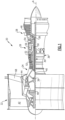
- FIG. 1 schematically illustrates a gas turbine engine 20.
- the gas turbine engine 20 is disclosed herein as a two-spool turbofan that generally incorporates a fan section 22, a compressor section 24, a combustor section 26 and a turbine section 28.
- Alternative engines might include an augmentor section (not shown) among other systems or features.
- the fan section 22 drives air along a bypass flowpath while the compressor section 24 drives air along a core flowpath for compression and communication into the combustor section 26 then expansion through the turbine section 28.
- FIG. 1 schematically illustrates a gas turbine engine 20.
- the gas turbine engine 20 is disclosed herein as a two-spool turbofan that generally incorporates a fan section 22, a compressor section 24, a combustor section 26 and a turbine section 28.
- Alternative engines might include an augmentor section (not shown) among other systems or features.
- the fan section 22 drives air along a bypass flowpath while the compressor section 24 drives air along a core flowpath for compression and communication into the combustor section 26
- the engine 20 generally includes a low spool 30 and a high spool 32 mounted for rotation about an engine central longitudinal axis A relative to an engine static structure 36 via several bearing systems 38. It should be understood that various bearing systems 38 at various locations may alternatively or additionally be provided.
- the low spool 30 generally includes an inner shaft 40 that interconnects a fan 42, a low pressure compressor 44 and a low pressure turbine 46.
- the inner shaft 40 may be connected to the fan 42 directly or through a geared architecture 48 to drive the fan 42 at a lower speed than the low spool 30 which in one disclosed non-limiting embodiment includes a gear reduction ratio of greater than 2.4:1.
- the high spool 32 includes an outer shaft 50 that interconnects a high pressure compressor 52 and high pressure turbine 54.
- a combustor 56 is arranged between the high pressure compressor 52 and the high pressure turbine 54.
- the inner shaft 40 and the outer shaft 50 are concentric and rotate about the engine central longitudinal axis A which is collinear with their longitudinal axes.
- the core airflow is compressed by the low pressure compressor 44 then the high pressure compressor 52, mixed and burned with fuel in the combustor 56, then expanded over the high pressure turbine 54 and low pressure turbine 46.
- the turbines 54, 46 rotationally drive the respective low spool 30 and high spool 32 in response to the expansion.
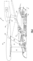
- the gas turbine engine 20 is mounted to an engine pylon structure 60 within an engine nacelle assembly 62 as is typical of an aircraft designed for subsonic operation.
- the nacelle assembly 62 generally includes a core nacelle 64 and a fan nacelle 66. It should be appreciated that the core nacelle 64 and the fan nacelle 66 may be of various configuration and may be at least partially integrated adjacent to, for example, an upper bi-fi and a lower bi-fi to define what are often referred to as D-doors.
- the fan nacelle 66 is at least partially supported relative to the core nacelle 64 by Fan Exit Guide Vanes (FEGVs) 68 which extend between a core case 70 and a fan case 72.
- FEGVs Fan Exit Guide Vanes
- the core case 70 and the fan case 72 are structural members that support the respective fan nacelle 66 and core nacelle 64 which define outer aerodynamic surfaces around the core case 70 and the fan case 72.
- the core case 70 is often referred to as the engine backbone and supports the rotational componentry therein. It should be understood that although a particular component arrangement is disclosed in the illustrated embodiment, various pylon structures, nacelle assemblies and engine case structures will benefit herefrom.
- An annular bypass flow path 74 is defined between the fan nacelle 66 and the core nacelle 64.
- the engine 20 generates a high bypass flow arrangement with a bypass ratio in which approximately eighty percent of the airflow which enters the fan nacelle 66 becomes bypass flow.
- the bypass flow communicates through the generally annular bypass flow path 74 and may be discharged from the engine 10 through a variable area fan nozzle (VAFN) 76 which defines a variable exit area for the bypass flow.
- VAFN variable area fan nozzle
- the VAFN 76 is operated to effectively vary the fan nozzle exit area to adjust fan bypass air flow such that the angle of attack or incidence on the fan blades is maintained close to the design incidence for efficient engine operation at other flight conditions, such as landing and takeoff to thus provide optimized engine operation over a range of flight conditions with respect to performance and other operational parameters such as noise levels.
- the engine 20 includes a thermal system 80 (illustrated schematically) powered by the low spool 30.
- the thermal system 80 integrates a Thermal Management System (TMS) 82 and an Environmental Control System (ECS) 84 powered by the low spool 30.
- TMS Thermal Management System
- ECS Environmental Control System
- the TMS 82 generally includes a TMS pump 86 such as an axial fan and an air-oil cooler (AOC) 88 which is in fluid communication with an engine lubrication system to cool engine oil.
- the ECS 84 generally includes an ECS pump 90 such as an impeller within a scroll discharge 91 and an air-air precooler 92 which operates to cool air for use in the aircraft cabin. The flow passes through the air-oil cooler (AOC) 88 to cool engine oil then through the air-air precooler 92 to cool the relatively hot ECS air.
- AOC air-oil cooler
- the coolers 88, 92 are integrated into one unit 93 to reduce system weight, size, and complexity. It should be appreciated that two or more coolers may be so integrated such that a cooling air flow passes through the air-oil cooler (AOC) 88 and then directly into air-air precooler 92. Arrangement of the air-oil cooler (AOC) 88 and the air-air precooler 92 in direct series as a single unit within a common housing 89 ( Figure 4 ) provides for a reduction in the overall packaging volume with reduced weight due in part to elimination of separate inlet and exit duct geometries. The sandwich structure also eliminates transition duct length associated with separate coolers and connecting flanges, as well as locates the fin media closer together to further reduce package volume.
- the decreased packaging volume trades favorably against a relatively small weight increase as the air-air precooler 92 may be sized somewhat larger than otherwise required to match a rectilinear shape and flow path geometry of the air-oil cooler (AOC) 88. That is, the geometry of the integral unit may result in one of the air-air precooler 92 or the air-oil cooler (AOC) 88 to be physically oversized.
- AOC air-oil cooler
- Fan bypass air from a scoop 94 within the bypass flow path 74 is selectively communicated to the TMS pump 86 and the ECS pump 90 through a bypass flow duct 96 within the core nacelle 64 ( Figure 2 ).
- the scoop 94 and bypass flow duct 96 in the disclosed non-limiting embodiment may be mounted to the core case 70 ( Figure 5 ) independent of the core nacelle 64 such that the core nacelle 64 is readily opened and closed with respect to the core case 70 without the heretofore necessity of a seal structure which may be relatively heavy in weight. That is, the scoop 94 and the bypass flow duct 96 are independent of the core nacelle 64 section commonly referred to as D-doors.
- Relatively hot bleed air sourced from the low pressure compressor 44 is also selectively communicated to the TMS pump 86 as well as the ECS pump 90 through a compressor flow duct 98.
- the compressor flow duct 98 communicates bleed air from the low pressure compressor 44. It should be appreciated that various duct and valve arrangements as may be utilized to tap the core case 70 to communicate bleed air from a multiple of circumferential locations around the low pressure compressor 44 for communication into the compressor flow duct 98.
- the bypass flow duct 96 meets with the compressor flow duct 98 at an intersection 100.
- a valve 102 is located within the intersection 100 to selectively communicate either fan bypass flow from the bypass flow duct 96 ( Figure 6 ) or bleed flow from the compressor flow duct 98 ( Figure 7 ) to the TMS pump 86 and the ECS pump 90. That is, the valve 102 is movable between a first position ( Figure 6 ) and a second position ( Figure 7 ) to selectively communicate either fan bypass flow or bleed flow.
- the valve 102 may be operated by an actuator 104 in response to a controller 106, such as a FADEC, to selectively communicate, for example, compressor bleed flow from the compressor flow duct 98 ( Figure 7 ) during an idle condition when fan bypass flow from the bypass flow duct 96 may not provide sufficient mass flow.
- a controller 106 such as a FADEC
- various other conditions may be utilized to control the valve 102 which may alternatively or additionally be operated in a variable manner to provide a combined flow of fan bypass flow from the bypass flow duct 96 and bleed flow from the compressor flow duct 98 ( Figure 8 ).
- the valve 102 may be infinitely variable between the first position ( Figure 6 ) and the second position ( Figure 7 ) to provide a desired percentage of each.
- the ECS pump 90 may be a centrifugal pump and the TMS pump 86 may be an axial pump.
- the TMS pump 86 generates, for example, an approximately 1.1:1 - 1.8:1, and preferably 1.4:1, pressure ratio from the relatively low pressure ratio fan bypass flow which is sufficient to provide the relatively coldest airflow into the AOC 88, which may be approximately 200 degrees F (93 degrees C).
- the relatively low pressure ratio fan bypass flow from the bypass flow path 74 is also provided to the ECS pump 90 to elevate the pressure thereof to, for example, an approximately 2:1 - 6:1, and preferably 4:1, pressure ratio at ground idle condition.
- the pressure increase provided by the ECS pump 90 also inherently increases temperature of the approximately 200 degrees F (93 degrees C) fan bypass flow to less than 600 degrees F (315 degrees C) for communication into the air-air precooler (PC) 92.
- the downstream flow from the air-oil cooler (AOC) 88 which may be approximately 300 degrees F (149 degrees C), is communicated into the air-air precooler 92. Discharge from the air-air precooler 92, which may be less than approximately 600 degrees F (315 degrees C), is then ejected into the annular bypass flow path 74 to provide thrust recovery.
- AOC air-oil cooler
- the relatively lower temperature air flow downstream of the ECS pump 90 which is typically less than approximately 600 degrees F (315 degrees C) is passed through the air-air precooler 92 and is cooled to approximately 400 degrees F (204 degrees C) for use as aircraft air system ECS air while the relatively higher temperature air discharged from air-air precooler 92, which may be less than approximately 600 degrees F (315 degrees C), is ejected into the annular bypass flow path 74 to provide thrust recovery.
- An efficient and compact thermal system 80 is thereby provided.
- the downstream flow from the air-air precooler 92 may also be utilized to provide pressurized cooling air for a hot bearing compartment for one or more of the bearing systems 38. Such components are typically toward an aft section of the engine 20 such as the #4 or #4/5 bearing compartments (illustrated schematically).
- the fan bypass flow is pumped to sufficient pressure (typically approximately 50psi (344.7 kPa)) and passed through the aircraft precooler 92 to reduce temperature sufficiently (typically to less than 450 degrees F (232 degrees C)) to be used directly as the bearing compartment cooling air.
- the precooler 92 thereby provides sufficiently low temperature air, instead of a dedicated buffer cooler, which may suffer from low inlet driving pressure at off-design conditions.
- the TMS pump 86 and the ECS pump 90 are driven through a constant speed transmission 110.
- the constant speed transmission 110 is driven by a towershaft 124 geared to the low spool 30.
- the speed of the towershaft 124 varies linearly with the speed of the low spool 30 which may operate at speed excursions of up to 80% between idle to max take-off conditions.
- the constant speed transmission 110 maintains constant output speed despite speed excursions of the low spool 30. That is, the constant speed transmission 110 provides, for example, a 5:1 continuously variable gear ratio capability which automatically selects the most optimum gear ratio to maintain the constant output speed in response to the low spool 30 speed excursions.
- the TMS pump 86 and the ECS pump 90 are driven through the constant speed transmission 110 with a single axial drive shaft 112. That is, the TMS pump 86 and the ECS pump 90 are driven at the same rotational speed along a common axis X by shaft 112.
- the TMS pump 86 and the ECS pump 90 are driven through the constant speed transmission 110 through separate drive shafts 114, 116 respectively. That is, the drive shafts 114, 116 are parallel and rotate about their own respective axis X1, X2.
- the parallel architecture facilitates direct drive of the drive shaft 114 by the constant speed transmission 110 while drive shaft 116 is driven by drive shaft 114 through a gearbox 118 or vice-versa.
- Gearbox 118 may be a direct, step-down or step-up gearbox such that shaft 116 is driven at the same rotational speed as shaft 114 or at a respective speed ratio with respect to shaft 114.
- the constant speed transmission 110 provides a constant output speed for shafts 114, 116 irrespective of low spool 30 speed excursions
- gearbox 118 provides a desired constant speed ratio between shafts 114 and 116.
- the high spool 32 may still be utilized to drive a relatively conventional accessory gearbox 120 to power a multiple of accessory components such as, for example, a deoiler (D), a hydraulic pump (HP), a lube pump (LP), a permanent magnet alternator (PMA), a fuel pump module (FMP), and other accessory components that may alternatively or additionally be provided.
- accessory components such as, for example, a deoiler (D), a hydraulic pump (HP), a lube pump (LP), a permanent magnet alternator (PMA), a fuel pump module (FMP), and other accessory components that may alternatively or additionally be provided.
- a high towershaft 122 is geared to the high spool 32 to drive the accessory gearbox 120 at a speed that varies linearly with the speed of the high spool 32.
- the high spool 32 operates at speed excursions less than the low spool 30 and typically of only up to 30% between idle to max take-off conditions. Power extraction from the relatively low-inertia high spool 32 for operation of low demand accessory components minimally affects engine performance. That is, the thermal system 80 includes relatively high demand, high power systems which are more constantly operated to provide a desired speed/mass flow as compared to the accessory components driven by the high spool 32.
- Utilization of the low spool 30 driven thermal system 80 increases operating range and decrease packaging volume. Integration of the, air-air precooler 92 into the common cooling/exit stream of the Air-Oil Cooler (AOC) 88 provides thrust recovery of the air-air precooler 92 discharge as compared to legacy configurations that dump precooler discharge flow overboard outside the fan bypass duct typically through the pylon fairing "thumbnail" or similar aircraft surface exposed to free stream air which negates thrust recovery benefits.
- AOC Air-Oil Cooler
- the dedicated ECS subsystem relieves the high spool 32 from inefficiencies and distortion due to bleeds at design and off-design points.
- ECS mass flow is approximately 1 lb (0.45 kg) per second, and efficiency gains from not bleeding this air from the high pressure compressor are about +2% HPC efficiency if power is instead extracted from the low spool, with reduced distortion due to lack of environmental control system bleeds.
- Exhaust gas temperature (EGT) at idle may also decrease by more than 230 degrees F (121 degrees C).
- Overall system weight also decreases due to the reduced ducting. Accordingly, valuable externals packaging space is facilitated by the reduction and integration of the TMS and ECS. Further, mechanical complexity is reduced to increase reliability as well as reduce cost and maintenance requirements.
- another disclosed non-limiting embodiment connects an integrated drive generator (IDG) 130 and a windmill pump 132 to the constant speed transmission 110.
- IDG integrated drive generator
- a windmill pump 132 to the constant speed transmission 110.
- IDG integrated drive generator
- additional or alternative components and systems may be driven by the constant speed transmission 110.
- the constant speed transmission 110 is driven by the low spool 30, the constant speed transmission 110 is driven even under "windmilling" conditions.
- the integrated drive generator (IDG) 130, the TMS pump 86 and the ECS pump 90 draw, in one example, between 90kVA and 200 kVA (96-214 hp).
- the TMS pump 86, the ECS pump 90, the integrated drive generator (IDG) 130 and the windmill pump 132 still operate and such operation may be utilized to control and reduce the speed of the fan 42 to a desired "windmilling" speed. Such speed reduction is achieved even in the unlikely presence of an imbalance while “windmilling" after fan blade liberation.
- Applicant has determined through simulation that in one example geared architecture gas turbine engine, upwards of 200hp (149 kW) of power extraction is available at acceptable fan 42 speeds during "windmilling" conditions.
- the various components driven by the constant speed transmission 110 and gear ratios provide multiple variables to achieve a desired "windmilling" speed of the fan 42 as well as the desired power generation of the integrated drive generator (IDG) 130, provide desired operational conditions of the TMS pump 86, the ECS pump 90, and the windmill pump 132. That is, the low spool 30 driven systems draw a required amount of power from the low spool 30 to operate as a brake to slow the low spool 30 to acceptable levels.
- IDG integrated drive generator
- the windmill pump 132 is alternatively or additionally "piggybacked" to the TMS pump 86 and/or the ECS pump 90. Alternately, the windmill pump 132 is independently driven such as in the parallel arrangement described above ( Figure 10 ).
- the windmill pump 132 pumps a lubricant to, for example, the geared architecture 48 to assure proper lubrication for an in-flight and ground “windmilling" condition.
- the windmill pump 132 further facilitates lubrication delivery for both the relatively higher in-flight "windmilling" condition as well as the relatively lower ground “windmilling” speed due to the geared relationship with the low spool 32.
- the windmill pump 132 may be selectively actuated or operated at constant speed throughout the mission cycle as opposed to varying with a speed of the geared architecture 48. Losses at an Aerodynamic Design Point (ADP; Cruise flight) and non-windmill conditions are reduced. Windmill pump size and weight are decreased compared to a core engine embedded version.
- the windmill pump 132 is remote from the engine core to facilitate increased maintenance accessibility as compared to conventional windmill pumps which are otherwise "buried" deep within the engine.
- the individual accessories are thereby insulated from the speed excursions of the low spool 30. For example, takeoff condition at 100% speed and an idle condition at 20% speed. So, the accessory components thereby experience a gear ratio advantage of 5:1 during normal operation.
- the windmill pump 132 is currently designed to work at low spool 30 speeds of just above "0" rpm to idle, and then covers the entire 80% speed excursion of the low spool 30. Since the windmill pump 132 is also driven through the constant speed transmission 110 the windmill pump 132 need only handle the speed excursion between "0" rpm and the idle speed condition. The remainder - idle to takeoff condition - is accounted for by the constant speed transmission 110. This facilities operation of a lubrication system with an optimized pump that handles narrow speed excursions, while being line replaceable.
- the low spool 30 driven integrated drive generator (IDG) 130 further facilitates integral power generation under "windmilling" conditions such that a Ram Air Turbine (RAT) emergency power generation system may no longer be required. Removal of the RAT reduces overall aircraft weight and obviates RAT deployment structures and packaging.
- RAT Ram Air Turbine
Description
- The present disclosure relates to a gas turbine engine, and more particularly to engine operations during "windmilling" conditions.
- In the highly unlikely event of an in-flight engine shutdown, a gas turbine engine fan has a tendency to spin at above-idle speed as air is forced through the fan due to forward aircraft motion. This unpowered fan rotation is commonly known as "windmilling". Even a fan of a shut down engine on the ground may "windmill" and may require at least some lubrication sufficient to sustain gears, bearings, seals, and other lubricated components.
- A prior art gas turbine engine having the features of the preamble of
claim 1 is disclosed inUS-2010/0086403 . Other prior art gas turbine engines are disclosed inUS 7 621 117 B2 ,US-2010/133813 A1 ,US-2008/047376 A1 andUS 4 912 921 A . - The present invention provides a gas turbine engine according to
claim 1, and a method according toclaim 5. - Various features will become apparent to those skilled in the art from the following detailed description of the disclosed non-limiting embodiment. The drawings that accompany the detailed description can be briefly described as follows:
-
Figure 1 is a schematic cross-sectional view of a gas turbine engine; -
Figure 2 is a schematic cross-sectional view of the gas turbine engine within a nacelle assembly; -
Figure 3 is an enlarged schematic view of a thermal system with an integrated Thermal Management System (TMS) and Environmental Control System (ECS) for the gas turbine engine; -
Figure 4 is a schematic view of an integrated air-oil cooler (AOC) / air-air precooler; -
Figure 5 is a perspective view of a duct arrangement with a scoop and a bypass flow duct within a core nacelle of the gas turbine engine; -
Figure 6 is a schematic view of the duct arrangement in bypass flow position; -
Figure 7 is a schematic view of the duct arrangement in a bleed flow position; -
Figure 8 is a schematic view of the duct arrangement in an intermediate position; -
Figure 9 is a schematic view of one disclosed non-limiting embodiment of a constant speed transmission which drives an ECS pump and a TMS pump in a serial arrangement; -
Figure 10 is a schematic view of another disclosed non-limiting embodiment of a constant speed transmission which drives an ECS pump and a TMS pump in a parallel arrangement; -
Figure 11 is a schematic view of an accessory and thermal system driven by the gas turbine engine; and -
Figure 12 is a schematic view of another disclosed non-limiting embodiment of a constant speed transmission which drives an IDG, a windmill pump, an ECS pump and a TMS pump. -
Figure 1 schematically illustrates agas turbine engine 20. Thegas turbine engine 20 is disclosed herein as a two-spool turbofan that generally incorporates afan section 22, acompressor section 24, acombustor section 26 and aturbine section 28. Alternative engines might include an augmentor section (not shown) among other systems or features. Thefan section 22 drives air along a bypass flowpath while thecompressor section 24 drives air along a core flowpath for compression and communication into thecombustor section 26 then expansion through theturbine section 28. Although depicted as a turbofan gas turbine engine in the disclosed non-limiting embodiment, it should be understood that the concepts described herein are not limited to use with turbofans as the teachings may be applied to other types of turbine engines, such as three-spool architectures. - The
engine 20 generally includes alow spool 30 and ahigh spool 32 mounted for rotation about an engine central longitudinal axis A relative to an enginestatic structure 36 viaseveral bearing systems 38. It should be understood thatvarious bearing systems 38 at various locations may alternatively or additionally be provided. - The
low spool 30 generally includes aninner shaft 40 that interconnects afan 42, alow pressure compressor 44 and alow pressure turbine 46. Theinner shaft 40 may be connected to thefan 42 directly or through a gearedarchitecture 48 to drive thefan 42 at a lower speed than thelow spool 30 which in one disclosed non-limiting embodiment includes a gear reduction ratio of greater than 2.4:1. Thehigh spool 32 includes anouter shaft 50 that interconnects ahigh pressure compressor 52 andhigh pressure turbine 54. Acombustor 56 is arranged between thehigh pressure compressor 52 and thehigh pressure turbine 54. Theinner shaft 40 and theouter shaft 50 are concentric and rotate about the engine central longitudinal axis A which is collinear with their longitudinal axes. - The core airflow is compressed by the
low pressure compressor 44 then thehigh pressure compressor 52, mixed and burned with fuel in thecombustor 56, then expanded over thehigh pressure turbine 54 andlow pressure turbine 46. Theturbines low spool 30 andhigh spool 32 in response to the expansion. - With reference to
Figure 2 , thegas turbine engine 20 is mounted to anengine pylon structure 60 within anengine nacelle assembly 62 as is typical of an aircraft designed for subsonic operation. Thenacelle assembly 62 generally includes acore nacelle 64 and afan nacelle 66. It should be appreciated that thecore nacelle 64 and thefan nacelle 66 may be of various configuration and may be at least partially integrated adjacent to, for example, an upper bi-fi and a lower bi-fi to define what are often referred to as D-doors. - The
fan nacelle 66 is at least partially supported relative to thecore nacelle 64 by Fan Exit Guide Vanes (FEGVs) 68 which extend between acore case 70 and afan case 72. Thecore case 70 and thefan case 72 are structural members that support therespective fan nacelle 66 andcore nacelle 64 which define outer aerodynamic surfaces around thecore case 70 and thefan case 72. Thecore case 70 is often referred to as the engine backbone and supports the rotational componentry therein. It should be understood that although a particular component arrangement is disclosed in the illustrated embodiment, various pylon structures, nacelle assemblies and engine case structures will benefit herefrom. - An annular
bypass flow path 74 is defined between thefan nacelle 66 and thecore nacelle 64. Theengine 20 generates a high bypass flow arrangement with a bypass ratio in which approximately eighty percent of the airflow which enters thefan nacelle 66 becomes bypass flow. In the disclosed non-limiting embodiment, the bypass flow communicates through the generally annularbypass flow path 74 and may be discharged from the engine 10 through a variable area fan nozzle (VAFN) 76 which defines a variable exit area for the bypass flow. - As the fan blades within the
fan section 22 are efficiently designed at a particular fixed stagger angle for an efficient cruise condition, the VAFN 76 is operated to effectively vary the fan nozzle exit area to adjust fan bypass air flow such that the angle of attack or incidence on the fan blades is maintained close to the design incidence for efficient engine operation at other flight conditions, such as landing and takeoff to thus provide optimized engine operation over a range of flight conditions with respect to performance and other operational parameters such as noise levels. - With reference to
Figure 3 , theengine 20 includes a thermal system 80 (illustrated schematically) powered by thelow spool 30. Thethermal system 80 integrates a Thermal Management System (TMS) 82 and an Environmental Control System (ECS) 84 powered by thelow spool 30. - The TMS 82 generally includes a
TMS pump 86 such as an axial fan and an air-oil cooler (AOC) 88 which is in fluid communication with an engine lubrication system to cool engine oil. The ECS 84 generally includes anECS pump 90 such as an impeller within ascroll discharge 91 and an air-air precooler 92 which operates to cool air for use in the aircraft cabin. The flow passes through the air-oil cooler (AOC) 88 to cool engine oil then through the air-air precooler 92 to cool the relatively hot ECS air. - In one disclosed, non-limiting embodiment, the
coolers unit 93 to reduce system weight, size, and complexity. It should be appreciated that two or more coolers may be so integrated such that a cooling air flow passes through the air-oil cooler (AOC) 88 and then directly into air-air precooler 92. Arrangement of the air-oil cooler (AOC) 88 and the air-air precooler 92 in direct series as a single unit within a common housing 89 (Figure 4 ) provides for a reduction in the overall packaging volume with reduced weight due in part to elimination of separate inlet and exit duct geometries. The sandwich structure also eliminates transition duct length associated with separate coolers and connecting flanges, as well as locates the fin media closer together to further reduce package volume. - For volume-challenged engine architectures, the decreased packaging volume trades favorably against a relatively small weight increase as the air-
air precooler 92 may be sized somewhat larger than otherwise required to match a rectilinear shape and flow path geometry of the air-oil cooler (AOC) 88. That is, the geometry of the integral unit may result in one of the air-air precooler 92 or the air-oil cooler (AOC) 88 to be physically oversized. Such an "oversized" relationship advantageous provides overly efficient operation and may somewhat increase weight - yet still less than separate coolers - as a tradeoff for elimination of separate inlet and exit duct geometries of separate coolers. - Fan bypass air from a
scoop 94 within thebypass flow path 74 is selectively communicated to theTMS pump 86 and theECS pump 90 through abypass flow duct 96 within the core nacelle 64 (Figure 2 ). Thescoop 94 andbypass flow duct 96 in the disclosed non-limiting embodiment may be mounted to the core case 70 (Figure 5 ) independent of thecore nacelle 64 such that thecore nacelle 64 is readily opened and closed with respect to thecore case 70 without the heretofore necessity of a seal structure which may be relatively heavy in weight. That is, thescoop 94 and thebypass flow duct 96 are independent of thecore nacelle 64 section commonly referred to as D-doors. - Relatively hot bleed air sourced from the
low pressure compressor 44 is also selectively communicated to theTMS pump 86 as well as theECS pump 90 through acompressor flow duct 98. The compressor flowduct 98 communicates bleed air from thelow pressure compressor 44. It should be appreciated that various duct and valve arrangements as may be utilized to tap thecore case 70 to communicate bleed air from a multiple of circumferential locations around thelow pressure compressor 44 for communication into thecompressor flow duct 98. - The bypass flow
duct 96 meets with thecompressor flow duct 98 at anintersection 100. Avalve 102 is located within theintersection 100 to selectively communicate either fan bypass flow from the bypass flow duct 96 (Figure 6 ) or bleed flow from the compressor flow duct 98 (Figure 7 ) to theTMS pump 86 and theECS pump 90. That is, thevalve 102 is movable between a first position (Figure 6 ) and a second position (Figure 7 ) to selectively communicate either fan bypass flow or bleed flow. - The
valve 102 may be operated by anactuator 104 in response to acontroller 106, such as a FADEC, to selectively communicate, for example, compressor bleed flow from the compressor flow duct 98 (Figure 7 ) during an idle condition when fan bypass flow from thebypass flow duct 96 may not provide sufficient mass flow. It should be understood that various other conditions may be utilized to control thevalve 102 which may alternatively or additionally be operated in a variable manner to provide a combined flow of fan bypass flow from thebypass flow duct 96 and bleed flow from the compressor flow duct 98 (Figure 8 ). In other words, thevalve 102 may be infinitely variable between the first position (Figure 6 ) and the second position (Figure 7 ) to provide a desired percentage of each. - In one disclosed, non-limiting embodiment, the
ECS pump 90 may be a centrifugal pump and theTMS pump 86 may be an axial pump. TheTMS pump 86 generates, for example, an approximately 1.1:1 - 1.8:1, and preferably 1.4:1, pressure ratio from the relatively low pressure ratio fan bypass flow which is sufficient to provide the relatively coldest airflow into theAOC 88, which may be approximately 200 degrees F (93 degrees C). The relatively low pressure ratio fan bypass flow from thebypass flow path 74 is also provided to theECS pump 90 to elevate the pressure thereof to, for example, an approximately 2:1 - 6:1, and preferably 4:1, pressure ratio at ground idle condition. The pressure increase provided by theECS pump 90 also inherently increases temperature of the approximately 200 degrees F (93 degrees C) fan bypass flow to less than 600 degrees F (315 degrees C) for communication into the air-air precooler (PC) 92. - The downstream flow from the air-oil cooler (AOC) 88, which may be approximately 300 degrees F (149 degrees C), is communicated into the air-
air precooler 92. Discharge from the air-air precooler 92, which may be less than approximately 600 degrees F (315 degrees C), is then ejected into the annularbypass flow path 74 to provide thrust recovery. That is, the relatively lower temperature air flow downstream of theECS pump 90, which is typically less than approximately 600 degrees F (315 degrees C), is passed through the air-air precooler 92 and is cooled to approximately 400 degrees F (204 degrees C) for use as aircraft air system ECS air while the relatively higher temperature air discharged from air-air precooler 92, which may be less than approximately 600 degrees F (315 degrees C), is ejected into the annularbypass flow path 74 to provide thrust recovery. An efficient and compactthermal system 80 is thereby provided. - The downstream flow from the air-
air precooler 92 may also be utilized to provide pressurized cooling air for a hot bearing compartment for one or more of the bearingsystems 38. Such components are typically toward an aft section of theengine 20 such as the #4 or #4/5 bearing compartments (illustrated schematically). The fan bypass flow is pumped to sufficient pressure (typically approximately 50psi (344.7 kPa)) and passed through theaircraft precooler 92 to reduce temperature sufficiently (typically to less than 450 degrees F (232 degrees C)) to be used directly as the bearing compartment cooling air. Theprecooler 92 thereby provides sufficiently low temperature air, instead of a dedicated buffer cooler, which may suffer from low inlet driving pressure at off-design conditions. - The
TMS pump 86 and theECS pump 90 are driven through aconstant speed transmission 110. Theconstant speed transmission 110 is driven by atowershaft 124 geared to thelow spool 30. The speed of thetowershaft 124 varies linearly with the speed of thelow spool 30 which may operate at speed excursions of up to 80% between idle to max take-off conditions. Theconstant speed transmission 110 maintains constant output speed despite speed excursions of thelow spool 30. That is, theconstant speed transmission 110 provides, for example, a 5:1 continuously variable gear ratio capability which automatically selects the most optimum gear ratio to maintain the constant output speed in response to thelow spool 30 speed excursions. - With reference to
Figure 9 , in one disclosed non-limiting embodiment, theTMS pump 86 and theECS pump 90 are driven through theconstant speed transmission 110 with a singleaxial drive shaft 112. That is, theTMS pump 86 and theECS pump 90 are driven at the same rotational speed along a common axis X byshaft 112. - With reference to
Figure 10 , in another disclosed non-limiting embodiment, theTMS pump 86 and theECS pump 90 are driven through theconstant speed transmission 110 throughseparate drive shafts drive shafts - The parallel architecture facilitates direct drive of the
drive shaft 114 by theconstant speed transmission 110 whiledrive shaft 116 is driven bydrive shaft 114 through agearbox 118 or vice-versa.Gearbox 118 may be a direct, step-down or step-up gearbox such thatshaft 116 is driven at the same rotational speed asshaft 114 or at a respective speed ratio with respect toshaft 114. In other words, theconstant speed transmission 110 provides a constant output speed forshafts low spool 30 speed excursions, andgearbox 118 provides a desired constant speed ratio betweenshafts - Utilization of the constant-
speed TMS pump 86 to drive air-oil cooler (AOC) 88 air flow increases the available pressure ratio for oil cooling. Power extraction from the relatively high-inertialow spool 30 also affects engine performance less adversely than does power extraction of a similar magnitude from thehigh spool 32. - With reference to
Figure 11 , thehigh spool 32 may still be utilized to drive a relatively conventionalaccessory gearbox 120 to power a multiple of accessory components such as, for example, a deoiler (D), a hydraulic pump (HP), a lube pump (LP), a permanent magnet alternator (PMA), a fuel pump module (FMP), and other accessory components that may alternatively or additionally be provided. - A
high towershaft 122 is geared to thehigh spool 32 to drive theaccessory gearbox 120 at a speed that varies linearly with the speed of thehigh spool 32. Thehigh spool 32 operates at speed excursions less than thelow spool 30 and typically of only up to 30% between idle to max take-off conditions. Power extraction from the relatively low-inertiahigh spool 32 for operation of low demand accessory components minimally affects engine performance. That is, thethermal system 80 includes relatively high demand, high power systems which are more constantly operated to provide a desired speed/mass flow as compared to the accessory components driven by thehigh spool 32. - Utilization of the
low spool 30 driventhermal system 80 increases operating range and decrease packaging volume. Integration of the, air-air precooler 92 into the common cooling/exit stream of the Air-Oil Cooler (AOC) 88 provides thrust recovery of the air-air precooler 92 discharge as compared to legacy configurations that dump precooler discharge flow overboard outside the fan bypass duct typically through the pylon fairing "thumbnail" or similar aircraft surface exposed to free stream air which negates thrust recovery benefits. - The dedicated ECS subsystem relieves the
high spool 32 from inefficiencies and distortion due to bleeds at design and off-design points. ECS mass flow is approximately 1 lb (0.45 kg) per second, and efficiency gains from not bleeding this air from the high pressure compressor are about +2% HPC efficiency if power is instead extracted from the low spool, with reduced distortion due to lack of environmental control system bleeds. Exhaust gas temperature (EGT) at idle may also decrease by more than 230 degrees F (121 degrees C). Overall system weight also decreases due to the reduced ducting. Accordingly, valuable externals packaging space is facilitated by the reduction and integration of the TMS and ECS. Further, mechanical complexity is reduced to increase reliability as well as reduce cost and maintenance requirements. - With reference to
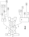
Figure 12 , another disclosed non-limiting embodiment connects an integrated drive generator (IDG) 130 and awindmill pump 132 to theconstant speed transmission 110. It should be appreciated that additional or alternative components and systems may be driven by theconstant speed transmission 110. As theconstant speed transmission 110 is driven by thelow spool 30, theconstant speed transmission 110 is driven even under "windmilling" conditions. - Under on-power operation, the integrated drive generator (IDG) 130, the
TMS pump 86 and theECS pump 90 draw, in one example, between 90kVA and 200 kVA (96-214 hp). - In a "windmilling" condition, the
TMS pump 86, theECS pump 90, the integrated drive generator (IDG) 130 and thewindmill pump 132 still operate and such operation may be utilized to control and reduce the speed of thefan 42 to a desired "windmilling" speed. Such speed reduction is achieved even in the unlikely presence of an imbalance while "windmilling" after fan blade liberation. - Applicant has determined through simulation that in one example geared architecture gas turbine engine, upwards of 200hp (149 kW) of power extraction is available at
acceptable fan 42 speeds during "windmilling" conditions. The various components driven by theconstant speed transmission 110 and gear ratios provide multiple variables to achieve a desired "windmilling" speed of thefan 42 as well as the desired power generation of the integrated drive generator (IDG) 130, provide desired operational conditions of theTMS pump 86, theECS pump 90, and thewindmill pump 132. That is, thelow spool 30 driven systems draw a required amount of power from thelow spool 30 to operate as a brake to slow thelow spool 30 to acceptable levels. - In one disclosed, non-limiting embodiment, the
windmill pump 132 is alternatively or additionally "piggybacked" to theTMS pump 86 and/or theECS pump 90. Alternately, thewindmill pump 132 is independently driven such as in the parallel arrangement described above (Figure 10 ). - The
windmill pump 132 pumps a lubricant to, for example, the gearedarchitecture 48 to assure proper lubrication for an in-flight and ground "windmilling" condition. Thewindmill pump 132 further facilitates lubrication delivery for both the relatively higher in-flight "windmilling" condition as well as the relatively lower ground "windmilling" speed due to the geared relationship with thelow spool 32. It should be understood that thewindmill pump 132 may be selectively actuated or operated at constant speed throughout the mission cycle as opposed to varying with a speed of the gearedarchitecture 48. Losses at an Aerodynamic Design Point (ADP; Cruise flight) and non-windmill conditions are reduced. Windmill pump size and weight are decreased compared to a core engine embedded version. In addition, thewindmill pump 132 is remote from the engine core to facilitate increased maintenance accessibility as compared to conventional windmill pumps which are otherwise "buried" deep within the engine. - As the
windmill pump 132 is driven by thelow spool 30 through theconstant speed transmission 110, the individual accessories are thereby insulated from the speed excursions of thelow spool 30. For example, takeoff condition at 100% speed and an idle condition at 20% speed. So, the accessory components thereby experience a gear ratio advantage of 5:1 during normal operation. Thewindmill pump 132 is currently designed to work atlow spool 30 speeds of just above "0" rpm to idle, and then covers the entire 80% speed excursion of thelow spool 30. Since thewindmill pump 132 is also driven through theconstant speed transmission 110 thewindmill pump 132 need only handle the speed excursion between "0" rpm and the idle speed condition. The remainder - idle to takeoff condition - is accounted for by theconstant speed transmission 110. This facilities operation of a lubrication system with an optimized pump that handles narrow speed excursions, while being line replaceable. - The
low spool 30 driven integrated drive generator (IDG) 130 further facilitates integral power generation under "windmilling" conditions such that a Ram Air Turbine (RAT) emergency power generation system may no longer be required. Removal of the RAT reduces overall aircraft weight and obviates RAT deployment structures and packaging. - It should be understood that like reference numerals identify corresponding or similar elements throughout the several drawings. It should also be understood that although a particular component arrangement is disclosed in the illustrated embodiment, other arrangements will benefit herefrom.
- Although particular step sequences are shown, described, and claimed, it should be understood that steps may be performed in any order, separated or combined unless otherwise indicated and will still benefit from the present disclosure.
- The foregoing description is exemplary rather than defined by the limitations within. Various non-limiting embodiments are disclosed herein, however, one of ordinary skill in the art would recognize that various modifications and variations in light of the above teachings will fall within the scope of the appended claims.
Claims (5)
- A gas turbine engine (20) comprising:a geared architecture (48);a fan section (22) including a fan; anda spool (30) which drives said geared architecture (48), wherein said spool (30) is a low spool, and said low spool (30) drives the fan (42) through the geared architecture (48), characterised in that the engine (20) further comprises:at least one component geared to said spool (30) to control a speed of said spool (30) during a "windmilling" condition, wherein said at least one component is operable to reduce a speed of the fan to a desired speed in response to the "windmilling" condition;a towershaft (124) geared to said spool (30); anda constant speed transmission (110) driven by said towershaft (124), wherein said at least one component is driven by said constant speed transmission (110), said at least one component including a windmill pump (132).
- The gas turbine engine as recited in claim 1, wherein said at least one component includes an axial pump (86) driven through said constant speed transmission (110).
- The gas turbine engine as recited in any preceding claim, wherein said at least one component includes a centrifugal pump (90) driven through said constant speed transmission (110).
- The gas turbine engine (20) as recited in any preceding claim, wherein said at least one component includes an Integrated Drive Generator (IDG) (130) driven through said constant speed transmission (110).
- A method of operating a gas turbine engine according to claim 1 during a "windmilling" condition comprising controlling a speed of the low spool (30) during the "windmilling" condition with the at least one component driven by a constant speed transmission (110) driven by the low spool (30), wherein the low spool (30) drives the fan (42) through the geared architecture (48), and further comprising driving the constant speed transmission with a towershaft (124) driven by said low spool (30).
Applications Claiming Priority (1)
| Application Number | Priority Date | Filing Date | Title |
|---|---|---|---|
| US13/278,317 US8966876B2 (en) | 2011-10-21 | 2011-10-21 | Controllable speed windmill operation of a gas turbine engine through low spool power extraction |
Publications (4)
| Publication Number | Publication Date |
|---|---|
| EP2584175A2 EP2584175A2 (en) | 2013-04-24 |
| EP2584175A3 EP2584175A3 (en) | 2016-10-12 |
| EP2584175B1 EP2584175B1 (en) | 2021-05-05 |
| EP2584175B2 true EP2584175B2 (en) | 2024-03-20 |
Family
ID=47172328
Family Applications (1)
| Application Number | Title | Priority Date | Filing Date |
|---|---|---|---|
| EP12189228.5A Active EP2584175B2 (en) | 2011-10-21 | 2012-10-19 | Operation of a gas turbine |
Country Status (2)
| Country | Link |
|---|---|
| US (1) | US8966876B2 (en) |
| EP (1) | EP2584175B2 (en) |
Families Citing this family (12)
| Publication number | Priority date | Publication date | Assignee | Title |
|---|---|---|---|---|
| US9200569B2 (en) * | 2011-10-21 | 2015-12-01 | United Technologies Corporation | Compartment cooling for a gas turbine engine |
| US8978351B2 (en) * | 2011-10-21 | 2015-03-17 | United Technologies Corporation | Integrated thermal management system and environmental control system for a gas turbine engine |
| US8966875B2 (en) * | 2011-10-21 | 2015-03-03 | United Technologies Corporation | Constant speed transmission for gas turbine engine |
| US9151224B2 (en) * | 2012-03-14 | 2015-10-06 | United Technologies Corporation | Constant-speed pump system for engine thermal management system AOC reduction and environmental control system loss elimination |
| US9163562B2 (en) * | 2012-03-14 | 2015-10-20 | United Technologies Corporation | Constant speed pump system for engine ECS loss elimination |
| US9394803B2 (en) * | 2012-03-14 | 2016-07-19 | United Technologies Corporation | Bypass air-pump system within the core engine to provide air for an environmental control system in a gas turbine engine |
| US10036329B2 (en) * | 2012-09-28 | 2018-07-31 | United Technologies Corporation | Gas turbine engine thermal management system for heat exchanger using bypass flow |
| JP6423999B2 (en) * | 2013-11-27 | 2018-11-14 | 三菱航空機株式会社 | aircraft |
| US10570824B2 (en) * | 2015-11-23 | 2020-02-25 | United Technologies Corporation | Near zero velocity lubrication system for a turbine engine |
| US10801413B2 (en) * | 2016-04-04 | 2020-10-13 | Raytheon Technologies Corporation | Electromagnetic anti-windmilling system |
| US10337349B2 (en) | 2016-04-27 | 2019-07-02 | United Technologies Corporation | Anti-windmilling system for a gas turbine engine |
| US11041444B2 (en) * | 2018-11-02 | 2021-06-22 | Pratt & Whitney Canada Corp. | Gas turbine engine with differential gearbox |
Family Cites Families (30)
| Publication number | Priority date | Publication date | Assignee | Title |
|---|---|---|---|---|
| US4912921A (en) | 1988-03-14 | 1990-04-03 | Sundstrand Corporation | Low speed spool emergency power extraction system |
| US5125597A (en) * | 1990-06-01 | 1992-06-30 | General Electric Company | Gas turbine engine powered aircraft environmental control system and boundary layer bleed with energy recovery system |
| GB9119852D0 (en) | 1991-09-17 | 1991-10-30 | Rolls Royce Plc | Ducted fan gas turbine engine accessory drive system |
| GB9313905D0 (en) | 1993-07-06 | 1993-08-25 | Rolls Royce Plc | Shaft power transfer in gas turbine engines |
| US5363641A (en) | 1993-08-06 | 1994-11-15 | United Technologies Corporation | Integrated auxiliary power system |
| US5845483A (en) | 1996-04-10 | 1998-12-08 | General Electric Company | Windmill engine starting system with fluid driven motor and pump |
| US6305156B1 (en) * | 1999-09-03 | 2001-10-23 | Alliedsignal Inc. | Integrated bleed air and engine starting system |
| FR2894621B1 (en) | 2005-12-09 | 2011-10-14 | Hispano Suiza Sa | AUXILIARY MACHINE DRIVE SYSTEM OF A DUAL BODY TURBOMOTEUR |
| US7861533B2 (en) | 2006-04-21 | 2011-01-04 | Pratt & Whitney Canada Corp | Relighting a turbofan engine |
| US20070265761A1 (en) * | 2006-05-11 | 2007-11-15 | Dooley Kevin A | Electric power generation system and method |
| US7621117B2 (en) | 2006-06-19 | 2009-11-24 | Pratt & Whitney Canada Corp. | Apparatus and method for controlling engine windmilling |
| DE102006039608A1 (en) * | 2006-08-24 | 2008-04-10 | Rolls-Royce Deutschland Ltd & Co Kg | Arrangement for energy extraction in a two-shaft engine |
| US7662059B2 (en) * | 2006-10-18 | 2010-02-16 | United Technologies Corporation | Lubrication of windmilling journal bearings |
| US7841163B2 (en) | 2006-11-13 | 2010-11-30 | Hamilton Sundstrand Corporation | Turbofan emergency generator |
| US7877980B2 (en) | 2006-12-28 | 2011-02-01 | General Electric Company | Convertible gas turbine engine |
| US7854582B2 (en) | 2007-05-08 | 2010-12-21 | Pratt & Whitney Canada Corp. | Operation of an aircraft engine after emergency shutdown |
| US8113317B2 (en) | 2007-07-06 | 2012-02-14 | Honeywell International Inc. | Electric motor driven lubrication pump control system and method that accomodates turbomachine windmill operation |
| TWI340204B (en) * | 2008-03-21 | 2011-04-11 | Ind Tech Res Inst | An improved power generating device with constant output rotation speed |
| US8146370B2 (en) * | 2008-05-21 | 2012-04-03 | Honeywell International Inc. | Turbine drive system with lock-up clutch and method |
| US8039983B2 (en) * | 2008-12-02 | 2011-10-18 | The Boeing Company | Systems and methods for providing AC power from multiple turbine engine spools |
| US9816441B2 (en) | 2009-03-30 | 2017-11-14 | United Technologies Corporation | Gas turbine engine with stacked accessory components |
| US8063501B2 (en) * | 2009-06-10 | 2011-11-22 | Hamilton Sundstrand Corporation | Gas turbine bleed energy recovery via counter rotating generator |
| US8522521B2 (en) * | 2010-11-09 | 2013-09-03 | Hamilton Sundstrand Corporation | Combined air turbine starter, air-oil cooler, and fan |
| EP2492451B1 (en) | 2011-02-28 | 2021-05-19 | Hamilton Sundstrand Corporation | Aircraft with low pressure spool emergency generator |
| US9080511B2 (en) * | 2011-10-21 | 2015-07-14 | United Technologies Corporation | Integrated thermal system for a gas turbine engine |
| US8966875B2 (en) * | 2011-10-21 | 2015-03-03 | United Technologies Corporation | Constant speed transmission for gas turbine engine |
| US8978352B2 (en) * | 2011-10-21 | 2015-03-17 | United Technologies Corporation | Apparatus and method for operating a gas turbine engine during windmilling |
| US20130098060A1 (en) * | 2011-10-21 | 2013-04-25 | Gabriel L. Suciu | Gas turbine engine onboard starter/generator system to absorb excess power |
| US8978351B2 (en) * | 2011-10-21 | 2015-03-17 | United Technologies Corporation | Integrated thermal management system and environmental control system for a gas turbine engine |
| US9200569B2 (en) * | 2011-10-21 | 2015-12-01 | United Technologies Corporation | Compartment cooling for a gas turbine engine |
-
2011
- 2011-10-21 US US13/278,317 patent/US8966876B2/en active Active
-
2012
- 2012-10-19 EP EP12189228.5A patent/EP2584175B2/en active Active
Also Published As
| Publication number | Publication date |
|---|---|
| EP2584175B1 (en) | 2021-05-05 |
| EP2584175A2 (en) | 2013-04-24 |
| EP2584175A3 (en) | 2016-10-12 |
| US8966876B2 (en) | 2015-03-03 |
| US20130098057A1 (en) | 2013-04-25 |
Similar Documents
| Publication | Publication Date | Title |
|---|---|---|
| EP2584174B1 (en) | Windmill operation of a gas turbine engine | |
| EP2584172B1 (en) | Constant speed transmission for gas turbine engine | |
| EP2584168B1 (en) | Integrated thermal system for a gas turbine engine | |
| EP2584169B1 (en) | Gas turbine engine with integrated thermal management system | |
| EP2584170B1 (en) | Compartment cooling for a gas turbine engine | |
| EP2584175B2 (en) | Operation of a gas turbine | |
| EP2584173B1 (en) | Gas Turbine Engine | |
| EP2065585B1 (en) | Gas turbine engine with pylon mounted accessory drive | |
| US7681402B2 (en) | Aeroengine oil tank fire protection system | |
| EP2011979B1 (en) | Generator with separate Oil System | |
| US11629646B2 (en) | Differential geared amplification of auxiliary power unit | |
| US20120117940A1 (en) | Gas turbine engine with pylon mounted accessory drive | |
| EP2617980A2 (en) | Gas turbine engines | |
| JPH04219422A (en) | Border bleeding system integrated with airplane engine starter | |
| EP3056714B1 (en) | Intercooled cooling air system using cooling compressor as starter | |
| RU2522208C1 (en) | Gas turbine engine pylon assembly and gas turbine engine system | |
| US20230011409A1 (en) | Method of managing thermal energy in a propulsion system | |
| WO2013165771A1 (en) | Geared turbofan with distributed accessory gearboxes |
Legal Events
| Date | Code | Title | Description |
|---|---|---|---|
| PUAI | Public reference made under article 153(3) epc to a published international application that has entered the european phase |
Free format text: ORIGINAL CODE: 0009012 |
|
| AK | Designated contracting states |
Kind code of ref document: A2 Designated state(s): AL AT BE BG CH CY CZ DE DK EE ES FI FR GB GR HR HU IE IS IT LI LT LU LV MC MK MT NL NO PL PT RO RS SE SI SK SM TR |
|
| AX | Request for extension of the european patent |
Extension state: BA ME |
|
| PUAL | Search report despatched |
Free format text: ORIGINAL CODE: 0009013 |
|
| AK | Designated contracting states |
Kind code of ref document: A3 Designated state(s): AL AT BE BG CH CY CZ DE DK EE ES FI FR GB GR HR HU IE IS IT LI LT LU LV MC MK MT NL NO PL PT RO RS SE SI SK SM TR |
|
| AX | Request for extension of the european patent |
Extension state: BA ME |
|
| RIC1 | Information provided on ipc code assigned before grant |
Ipc: F02C 3/107 20060101ALI20160908BHEP Ipc: F02C 7/32 20060101ALI20160908BHEP Ipc: F02C 9/16 20060101AFI20160908BHEP |
|
| RAP1 | Party data changed (applicant data changed or rights of an application transferred) |
Owner name: UNITED TECHNOLOGIES CORPORATION |
|
| STAA | Information on the status of an ep patent application or granted ep patent |
Free format text: STATUS: REQUEST FOR EXAMINATION WAS MADE |
|
| 17P | Request for examination filed |
Effective date: 20170412 |
|
| RBV | Designated contracting states (corrected) |
Designated state(s): AL AT BE BG CH CY CZ DE DK EE ES FI FR GB GR HR HU IE IS IT LI LT LU LV MC MK MT NL NO PL PT RO RS SE SI SK SM TR |
|
| STAA | Information on the status of an ep patent application or granted ep patent |
Free format text: STATUS: EXAMINATION IS IN PROGRESS |
|
| 17Q | First examination report despatched |
Effective date: 20200318 |
|
| GRAP | Despatch of communication of intention to grant a patent |
Free format text: ORIGINAL CODE: EPIDOSNIGR1 |
|
| STAA | Information on the status of an ep patent application or granted ep patent |
Free format text: STATUS: GRANT OF PATENT IS INTENDED |
|
| INTG | Intention to grant announced |
Effective date: 20201118 |
|
| RAP1 | Party data changed (applicant data changed or rights of an application transferred) |
Owner name: RAYTHEON TECHNOLOGIES CORPORATION |
|
| GRAS | Grant fee paid |
Free format text: ORIGINAL CODE: EPIDOSNIGR3 |
|
| GRAA | (expected) grant |
Free format text: ORIGINAL CODE: 0009210 |
|
| STAA | Information on the status of an ep patent application or granted ep patent |
Free format text: STATUS: THE PATENT HAS BEEN GRANTED |
|
| AK | Designated contracting states |
Kind code of ref document: B1 Designated state(s): AL AT BE BG CH CY CZ DE DK EE ES FI FR GB GR HR HU IE IS IT LI LT LU LV MC MK MT NL NO PL PT RO RS SE SI SK SM TR |
|
| REG | Reference to a national code |
Ref country code: GB Ref legal event code: FG4D |
|
| REG | Reference to a national code |
Ref country code: CH Ref legal event code: EP |
|
| REG | Reference to a national code |
Ref country code: AT Ref legal event code: REF Ref document number: 1390082 Country of ref document: AT Kind code of ref document: T Effective date: 20210515 |
|
| REG | Reference to a national code |
Ref country code: IE Ref legal event code: FG4D |
|
| REG | Reference to a national code |
Ref country code: DE Ref legal event code: R096 Ref document number: 602012075457 Country of ref document: DE |
|
| REG | Reference to a national code |
Ref country code: LT Ref legal event code: MG9D |
|
| REG | Reference to a national code |
Ref country code: AT Ref legal event code: MK05 Ref document number: 1390082 Country of ref document: AT Kind code of ref document: T Effective date: 20210505 |
|
| PG25 | Lapsed in a contracting state [announced via postgrant information from national office to epo] |
Ref country code: BG Free format text: LAPSE BECAUSE OF FAILURE TO SUBMIT A TRANSLATION OF THE DESCRIPTION OR TO PAY THE FEE WITHIN THE PRESCRIBED TIME-LIMIT Effective date: 20210805 Ref country code: AT Free format text: LAPSE BECAUSE OF FAILURE TO SUBMIT A TRANSLATION OF THE DESCRIPTION OR TO PAY THE FEE WITHIN THE PRESCRIBED TIME-LIMIT Effective date: 20210505 Ref country code: HR Free format text: LAPSE BECAUSE OF FAILURE TO SUBMIT A TRANSLATION OF THE DESCRIPTION OR TO PAY THE FEE WITHIN THE PRESCRIBED TIME-LIMIT Effective date: 20210505 Ref country code: FI Free format text: LAPSE BECAUSE OF FAILURE TO SUBMIT A TRANSLATION OF THE DESCRIPTION OR TO PAY THE FEE WITHIN THE PRESCRIBED TIME-LIMIT Effective date: 20210505 Ref country code: LT Free format text: LAPSE BECAUSE OF FAILURE TO SUBMIT A TRANSLATION OF THE DESCRIPTION OR TO PAY THE FEE WITHIN THE PRESCRIBED TIME-LIMIT Effective date: 20210505 |
|
| PG25 | Lapsed in a contracting state [announced via postgrant information from national office to epo] |
Ref country code: PL Free format text: LAPSE BECAUSE OF FAILURE TO SUBMIT A TRANSLATION OF THE DESCRIPTION OR TO PAY THE FEE WITHIN THE PRESCRIBED TIME-LIMIT Effective date: 20210505 Ref country code: NO Free format text: LAPSE BECAUSE OF FAILURE TO SUBMIT A TRANSLATION OF THE DESCRIPTION OR TO PAY THE FEE WITHIN THE PRESCRIBED TIME-LIMIT Effective date: 20210805 Ref country code: PT Free format text: LAPSE BECAUSE OF FAILURE TO SUBMIT A TRANSLATION OF THE DESCRIPTION OR TO PAY THE FEE WITHIN THE PRESCRIBED TIME-LIMIT Effective date: 20210906 Ref country code: ES Free format text: LAPSE BECAUSE OF FAILURE TO SUBMIT A TRANSLATION OF THE DESCRIPTION OR TO PAY THE FEE WITHIN THE PRESCRIBED TIME-LIMIT Effective date: 20210505 Ref country code: LV Free format text: LAPSE BECAUSE OF FAILURE TO SUBMIT A TRANSLATION OF THE DESCRIPTION OR TO PAY THE FEE WITHIN THE PRESCRIBED TIME-LIMIT Effective date: 20210505 Ref country code: GR Free format text: LAPSE BECAUSE OF FAILURE TO SUBMIT A TRANSLATION OF THE DESCRIPTION OR TO PAY THE FEE WITHIN THE PRESCRIBED TIME-LIMIT Effective date: 20210806 Ref country code: IS Free format text: LAPSE BECAUSE OF FAILURE TO SUBMIT A TRANSLATION OF THE DESCRIPTION OR TO PAY THE FEE WITHIN THE PRESCRIBED TIME-LIMIT Effective date: 20210905 Ref country code: RS Free format text: LAPSE BECAUSE OF FAILURE TO SUBMIT A TRANSLATION OF THE DESCRIPTION OR TO PAY THE FEE WITHIN THE PRESCRIBED TIME-LIMIT Effective date: 20210505 Ref country code: SE Free format text: LAPSE BECAUSE OF FAILURE TO SUBMIT A TRANSLATION OF THE DESCRIPTION OR TO PAY THE FEE WITHIN THE PRESCRIBED TIME-LIMIT Effective date: 20210505 |
|
| REG | Reference to a national code |
Ref country code: NL Ref legal event code: MP Effective date: 20210505 |
|
| PG25 | Lapsed in a contracting state [announced via postgrant information from national office to epo] |
Ref country code: NL Free format text: LAPSE BECAUSE OF FAILURE TO SUBMIT A TRANSLATION OF THE DESCRIPTION OR TO PAY THE FEE WITHIN THE PRESCRIBED TIME-LIMIT Effective date: 20210505 |
|
| PG25 | Lapsed in a contracting state [announced via postgrant information from national office to epo] |
Ref country code: SK Free format text: LAPSE BECAUSE OF FAILURE TO SUBMIT A TRANSLATION OF THE DESCRIPTION OR TO PAY THE FEE WITHIN THE PRESCRIBED TIME-LIMIT Effective date: 20210505 Ref country code: SM Free format text: LAPSE BECAUSE OF FAILURE TO SUBMIT A TRANSLATION OF THE DESCRIPTION OR TO PAY THE FEE WITHIN THE PRESCRIBED TIME-LIMIT Effective date: 20210505 Ref country code: EE Free format text: LAPSE BECAUSE OF FAILURE TO SUBMIT A TRANSLATION OF THE DESCRIPTION OR TO PAY THE FEE WITHIN THE PRESCRIBED TIME-LIMIT Effective date: 20210505 Ref country code: CZ Free format text: LAPSE BECAUSE OF FAILURE TO SUBMIT A TRANSLATION OF THE DESCRIPTION OR TO PAY THE FEE WITHIN THE PRESCRIBED TIME-LIMIT Effective date: 20210505 Ref country code: DK Free format text: LAPSE BECAUSE OF FAILURE TO SUBMIT A TRANSLATION OF THE DESCRIPTION OR TO PAY THE FEE WITHIN THE PRESCRIBED TIME-LIMIT Effective date: 20210505 Ref country code: RO Free format text: LAPSE BECAUSE OF FAILURE TO SUBMIT A TRANSLATION OF THE DESCRIPTION OR TO PAY THE FEE WITHIN THE PRESCRIBED TIME-LIMIT Effective date: 20210505 |
|
| REG | Reference to a national code |
Ref country code: DE Ref legal event code: R026 Ref document number: 602012075457 Country of ref document: DE |
|
| PLBI | Opposition filed |
Free format text: ORIGINAL CODE: 0009260 |
|
| PLAX | Notice of opposition and request to file observation + time limit sent |
Free format text: ORIGINAL CODE: EPIDOSNOBS2 |
|
| 26 | Opposition filed |
Opponent name: SAFRAN AIRCRAFT ENGINES Effective date: 20220207 |
|
| REG | Reference to a national code |
Ref country code: CH Ref legal event code: PL |
|
| PG25 | Lapsed in a contracting state [announced via postgrant information from national office to epo] |
Ref country code: IS Free format text: LAPSE BECAUSE OF FAILURE TO SUBMIT A TRANSLATION OF THE DESCRIPTION OR TO PAY THE FEE WITHIN THE PRESCRIBED TIME-LIMIT Effective date: 20210905 Ref country code: AL Free format text: LAPSE BECAUSE OF FAILURE TO SUBMIT A TRANSLATION OF THE DESCRIPTION OR TO PAY THE FEE WITHIN THE PRESCRIBED TIME-LIMIT Effective date: 20210505 |
|
| REG | Reference to a national code |
Ref country code: BE Ref legal event code: MM Effective date: 20211031 |
|
| PG25 | Lapsed in a contracting state [announced via postgrant information from national office to epo] |
Ref country code: MC Free format text: LAPSE BECAUSE OF FAILURE TO SUBMIT A TRANSLATION OF THE DESCRIPTION OR TO PAY THE FEE WITHIN THE PRESCRIBED TIME-LIMIT Effective date: 20210505 |
|
| PLBB | Reply of patent proprietor to notice(s) of opposition received |
Free format text: ORIGINAL CODE: EPIDOSNOBS3 |
|
| PG25 | Lapsed in a contracting state [announced via postgrant information from national office to epo] |
Ref country code: LU Free format text: LAPSE BECAUSE OF NON-PAYMENT OF DUE FEES Effective date: 20211019 Ref country code: IT Free format text: LAPSE BECAUSE OF FAILURE TO SUBMIT A TRANSLATION OF THE DESCRIPTION OR TO PAY THE FEE WITHIN THE PRESCRIBED TIME-LIMIT Effective date: 20210505 Ref country code: BE Free format text: LAPSE BECAUSE OF NON-PAYMENT OF DUE FEES Effective date: 20211031 |
|
| PG25 | Lapsed in a contracting state [announced via postgrant information from national office to epo] |
Ref country code: LI Free format text: LAPSE BECAUSE OF NON-PAYMENT OF DUE FEES Effective date: 20211031 Ref country code: CH Free format text: LAPSE BECAUSE OF NON-PAYMENT OF DUE FEES Effective date: 20211031 |
|
| PG25 | Lapsed in a contracting state [announced via postgrant information from national office to epo] |
Ref country code: IE Free format text: LAPSE BECAUSE OF NON-PAYMENT OF DUE FEES Effective date: 20211019 |
|
| PG25 | Lapsed in a contracting state [announced via postgrant information from national office to epo] |
Ref country code: HU Free format text: LAPSE BECAUSE OF FAILURE TO SUBMIT A TRANSLATION OF THE DESCRIPTION OR TO PAY THE FEE WITHIN THE PRESCRIBED TIME-LIMIT; INVALID AB INITIO Effective date: 20121019 Ref country code: CY Free format text: LAPSE BECAUSE OF FAILURE TO SUBMIT A TRANSLATION OF THE DESCRIPTION OR TO PAY THE FEE WITHIN THE PRESCRIBED TIME-LIMIT Effective date: 20210505 |
|
| REG | Reference to a national code |
Ref country code: CH Ref legal event code: PK Free format text: TITEL |
|
| P01 | Opt-out of the competence of the unified patent court (upc) registered |
Effective date: 20230520 |
|
| PGFP | Annual fee paid to national office [announced via postgrant information from national office to epo] |
Ref country code: GB Payment date: 20230920 Year of fee payment: 12 |
|
| RAP4 | Party data changed (patent owner data changed or rights of a patent transferred) |
Owner name: RTX CORPORATION |
|
| PGFP | Annual fee paid to national office [announced via postgrant information from national office to epo] |
Ref country code: FR Payment date: 20230920 Year of fee payment: 12 |
|
| PGFP | Annual fee paid to national office [announced via postgrant information from national office to epo] |
Ref country code: DE Payment date: 20230920 Year of fee payment: 12 |
|
| PUAH | Patent maintained in amended form |
Free format text: ORIGINAL CODE: 0009272 |
|
| STAA | Information on the status of an ep patent application or granted ep patent |
Free format text: STATUS: PATENT MAINTAINED AS AMENDED |
|
| 27A | Patent maintained in amended form |
Effective date: 20240320 |
|
| AK | Designated contracting states |
Kind code of ref document: B2 Designated state(s): AL AT BE BG CH CY CZ DE DK EE ES FI FR GB GR HR HU IE IS IT LI LT LU LV MC MK MT NL NO PL PT RO RS SE SI SK SM TR |
|
| REG | Reference to a national code |
Ref country code: DE Ref legal event code: R102 Ref document number: 602012075457 Country of ref document: DE |