EP4151805A1 - Work machine - Google Patents
Work machine Download PDFInfo
- Publication number
- EP4151805A1 EP4151805A1 EP21874866.3A EP21874866A EP4151805A1 EP 4151805 A1 EP4151805 A1 EP 4151805A1 EP 21874866 A EP21874866 A EP 21874866A EP 4151805 A1 EP4151805 A1 EP 4151805A1
- Authority
- EP
- European Patent Office
- Prior art keywords
- disposed
- work machine
- frame
- detector
- counterweight
- Prior art date
- Legal status (The legal status is an assumption and is not a legal conclusion. Google has not performed a legal analysis and makes no representation as to the accuracy of the status listed.)
- Pending
Links
Images





Classifications
-
- E—FIXED CONSTRUCTIONS
- E02—HYDRAULIC ENGINEERING; FOUNDATIONS; SOIL SHIFTING
- E02F—DREDGING; SOIL-SHIFTING
- E02F9/00—Component parts of dredgers or soil-shifting machines, not restricted to one of the kinds covered by groups E02F3/00 - E02F7/00
- E02F9/26—Indicating devices
-
- E—FIXED CONSTRUCTIONS
- E02—HYDRAULIC ENGINEERING; FOUNDATIONS; SOIL SHIFTING
- E02F—DREDGING; SOIL-SHIFTING
- E02F9/00—Component parts of dredgers or soil-shifting machines, not restricted to one of the kinds covered by groups E02F3/00 - E02F7/00
- E02F9/08—Superstructures; Supports for superstructures
- E02F9/0841—Articulated frame, i.e. having at least one pivot point between two travelling gear units
-
- E—FIXED CONSTRUCTIONS
- E02—HYDRAULIC ENGINEERING; FOUNDATIONS; SOIL SHIFTING
- E02F—DREDGING; SOIL-SHIFTING
- E02F3/00—Dredgers; Soil-shifting machines
- E02F3/04—Dredgers; Soil-shifting machines mechanically-driven
- E02F3/28—Dredgers; Soil-shifting machines mechanically-driven with digging tools mounted on a dipper- or bucket-arm, i.e. there is either one arm or a pair of arms, e.g. dippers, buckets
- E02F3/283—Dredgers; Soil-shifting machines mechanically-driven with digging tools mounted on a dipper- or bucket-arm, i.e. there is either one arm or a pair of arms, e.g. dippers, buckets with a single arm pivoted directly on the chassis
-
- E—FIXED CONSTRUCTIONS
- E02—HYDRAULIC ENGINEERING; FOUNDATIONS; SOIL SHIFTING
- E02F—DREDGING; SOIL-SHIFTING
- E02F9/00—Component parts of dredgers or soil-shifting machines, not restricted to one of the kinds covered by groups E02F3/00 - E02F7/00
- E02F9/08—Superstructures; Supports for superstructures
- E02F9/0858—Arrangement of component parts installed on superstructures not otherwise provided for, e.g. electric components, fenders, air-conditioning units
-
- E—FIXED CONSTRUCTIONS
- E02—HYDRAULIC ENGINEERING; FOUNDATIONS; SOIL SHIFTING
- E02F—DREDGING; SOIL-SHIFTING
- E02F9/00—Component parts of dredgers or soil-shifting machines, not restricted to one of the kinds covered by groups E02F3/00 - E02F7/00
- E02F9/08—Superstructures; Supports for superstructures
- E02F9/0858—Arrangement of component parts installed on superstructures not otherwise provided for, e.g. electric components, fenders, air-conditioning units
- E02F9/0866—Engine compartment, e.g. heat exchangers, exhaust filters, cooling devices, silencers, mufflers, position of hydraulic pumps in the engine compartment
-
- E—FIXED CONSTRUCTIONS
- E02—HYDRAULIC ENGINEERING; FOUNDATIONS; SOIL SHIFTING
- E02F—DREDGING; SOIL-SHIFTING
- E02F9/00—Component parts of dredgers or soil-shifting machines, not restricted to one of the kinds covered by groups E02F3/00 - E02F7/00
- E02F9/08—Superstructures; Supports for superstructures
- E02F9/0858—Arrangement of component parts installed on superstructures not otherwise provided for, e.g. electric components, fenders, air-conditioning units
- E02F9/0891—Lids or bonnets or doors or details thereof
-
- E—FIXED CONSTRUCTIONS
- E02—HYDRAULIC ENGINEERING; FOUNDATIONS; SOIL SHIFTING
- E02F—DREDGING; SOIL-SHIFTING
- E02F9/00—Component parts of dredgers or soil-shifting machines, not restricted to one of the kinds covered by groups E02F3/00 - E02F7/00
- E02F9/24—Safety devices, e.g. for preventing overload
-
- E—FIXED CONSTRUCTIONS
- E02—HYDRAULIC ENGINEERING; FOUNDATIONS; SOIL SHIFTING
- E02F—DREDGING; SOIL-SHIFTING
- E02F9/00—Component parts of dredgers or soil-shifting machines, not restricted to one of the kinds covered by groups E02F3/00 - E02F7/00
- E02F9/26—Indicating devices
- E02F9/261—Surveying the work-site to be treated
-
- G—PHYSICS
- G01—MEASURING; TESTING
- G01S—RADIO DIRECTION-FINDING; RADIO NAVIGATION; DETERMINING DISTANCE OR VELOCITY BY USE OF RADIO WAVES; LOCATING OR PRESENCE-DETECTING BY USE OF THE REFLECTION OR RERADIATION OF RADIO WAVES; ANALOGOUS ARRANGEMENTS USING OTHER WAVES
- G01S13/00—Systems using the reflection or reradiation of radio waves, e.g. radar systems; Analogous systems using reflection or reradiation of waves whose nature or wavelength is irrelevant or unspecified
- G01S13/88—Radar or analogous systems specially adapted for specific applications
- G01S13/93—Radar or analogous systems specially adapted for specific applications for anti-collision purposes
- G01S13/931—Radar or analogous systems specially adapted for specific applications for anti-collision purposes of land vehicles
-
- G—PHYSICS
- G01—MEASURING; TESTING
- G01S—RADIO DIRECTION-FINDING; RADIO NAVIGATION; DETERMINING DISTANCE OR VELOCITY BY USE OF RADIO WAVES; LOCATING OR PRESENCE-DETECTING BY USE OF THE REFLECTION OR RERADIATION OF RADIO WAVES; ANALOGOUS ARRANGEMENTS USING OTHER WAVES
- G01S7/00—Details of systems according to groups G01S13/00, G01S15/00, G01S17/00
- G01S7/02—Details of systems according to groups G01S13/00, G01S15/00, G01S17/00 of systems according to group G01S13/00
- G01S7/027—Constructional details of housings, e.g. form, type, material or ruggedness
- G01S7/028—Miniaturisation, e.g. surface mounted device [SMD] packaging or housings
-
- E—FIXED CONSTRUCTIONS
- E02—HYDRAULIC ENGINEERING; FOUNDATIONS; SOIL SHIFTING
- E02F—DREDGING; SOIL-SHIFTING
- E02F9/00—Component parts of dredgers or soil-shifting machines, not restricted to one of the kinds covered by groups E02F3/00 - E02F7/00
- E02F9/18—Counterweights
-
- G—PHYSICS
- G01—MEASURING; TESTING
- G01S—RADIO DIRECTION-FINDING; RADIO NAVIGATION; DETERMINING DISTANCE OR VELOCITY BY USE OF RADIO WAVES; LOCATING OR PRESENCE-DETECTING BY USE OF THE REFLECTION OR RERADIATION OF RADIO WAVES; ANALOGOUS ARRANGEMENTS USING OTHER WAVES
- G01S13/00—Systems using the reflection or reradiation of radio waves, e.g. radar systems; Analogous systems using reflection or reradiation of waves whose nature or wavelength is irrelevant or unspecified
- G01S13/88—Radar or analogous systems specially adapted for specific applications
- G01S13/93—Radar or analogous systems specially adapted for specific applications for anti-collision purposes
- G01S13/931—Radar or analogous systems specially adapted for specific applications for anti-collision purposes of land vehicles
- G01S2013/9327—Sensor installation details
- G01S2013/93271—Sensor installation details in the front of the vehicles
Definitions
- the present invention relates to a work machine.
- Collision suppression system has been proposed for detecting an obstacle to the rear and suppressing a collision in a work machine such as a wheel loader (for example, see Patent Document 1).
- a radar device or the like fixed to the rear end of the work machine detects an obstacle existing in the rear of the engine room that is difficult to see from the cab.
- Patent Document No. 1 Registration of Utility Model No. 3219005
- the above-mentioned fixed radar device has a limited detection range, while a vehicle having an articulated mechanism such as a wheel loader has a small turning radius, so, it is necessary to widen the detection range when turning. Therefore it was difficult to detect an obstacle appropriately.
- An object of the present disclosure is to provide a work machine capable of detecting an obstacle more appropriately.
- a work machine comprise a vehicle body and a plurality of radar devices.
- the vehicle body includes a front frame and a rear frame. Traveling wheels are disposed on the front frame. Traveling wheels are disposed on the rear frame.
- the rear frame is relatively operably connected to the front frame with an articulated mechanism.
- the plurality of radar devices are positioned on a right side and a left side of a central axis along a front-rear direction of the rear frame and installed at a rear part of the vehicle body.
- Each radar device of the plurality of radar devices includes a detector configured to detect an object. The detector is disposed facing outward from a direction parallel to the central axis.
- Awheel loader as an example of a work machine according to the present disclosure will be described below with reference to the drawings.
- FIG. 1 is a side view illustrating the wheel loader 100 (an example of a work machine) of present embodiment.
- a wheel loader 100 of present embodiment includes a vehicle body 1 and a plurality of radar devices 30.
- the vehicle body 1 includes an articulated mechanism.
- a plurality of radar devices 30 are disposed on the rear part of the vehicle body 1.
- a vehicle body 1 includes a vehicle body frame 2, a work implement 3, a pair of front tires 4 (an example of traveling wheels), a cab 5, an engine room 6, a pair of rear tires 7 (an example of traveling wheels), and a steering cylinder 9, and a counterweight 10.
- front, “rear”, “right”, “left”, “up”, and “down” indicate directions relative to a state of looking forward from the driver's seat. Also, “vehicle width direction” and “left-right direction” have the same meaning.
- the front-rear direction is indicated by X
- the front direction is indicated by Xf
- the rear direction is indicated by Xb.
- the wheel loader 100 performs work such as earth and sand loading by using the work implement 3.
- the vehicle body frame 2 is a so-called articulated construction and includes a front frame 11, a rear frame 12, and a coupling shaft part 13.
- the front frame 11 is disposed in front of the rear frame 12.
- the coupling shaft part 13 is provided in the center in the vehicle width direction and couples the front frame 11 and the rear frame 12 to each other in a manner that allows swinging.
- the pair of front tires 4 are attached to the left and right of the front frame 11.
- the pair of rear tires 7 are attached to the left and right of the rear frame 12.
- the work implement 3 is driven by hydraulic fluid from a work implement pump (not shown).
- the work implement 3 is attached to the front part of the front frame 11 in a manner that allows swinging.
- the work implement 3 includes a boom 14, a bucket 15, a lift cylinder 16, a bucket cylinder 17, and a bell crank 18.
- the base end of the boom 14 is rotatably attached to a front part of the front frame 11.
- the tip end of the boom 14 is rotatably attached to a rear part of the bucket 15.
- the rear part of the bucket 15 is on the opposite side from an opening 15b.
- the tip end of a cylinder rod of the lift cylinder 16 is rotatably attached between the base end and the tip end of the boom 14.
- the cylinder body of the lift cylinder 16 is rotatably attached to the front frame 11.
- One end part of the bell crank 18 is rotatably attached to the tip end of a cylinder rod of the bucket cylinder 17.
- the other end part of the bell crank 18 is rotatably attached to a rear part of the bucket 15.
- the bell crank 18 is rotatably supported by a bell crank support 14d near the middle of the boom 14 between either end.
- the cylinder body of the bucket cylinder 17 is rotatably attached to the front frame 11. The extension/contraction force of the bucket cylinder 17 is converted to rotational movement by the bell crank 18 and is transmitted to the bucket 15.
- the bucket 15 is rotatably attached to the tip end of the boom 14 so as to open toward the front. By extending and contracting the bucket cylinder 17, the bucket 15 rotates with respect to the boom 14 and performs a tilting motion and a dumping motion.
- the cab 5 is disposed on the rear frame 12.
- a steering handle for performing steering operations, a lever for operating the work implement 3, and various display devices are disposed inside the cab 5.
- the engine room 6 is disposed to the rear of the cab 5 and on the rear frame 12 and accommodates an engine (not shown).
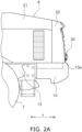
- FIG. 2A is a side view illustrating the rear part.
- FIG. 2B is a rear view of wheel loader 100.
- FIG. 2C is a perspective view illustrating the rear part of wheel loader 100.
- the counterweight 10 is attached to the rear part of the rear frame 12.
- the counterweight 10 is disposed so as to protrude rearward from below the engine room 6.
- a part of the counterweight 10 is located in the rear of the engine room 6.
- a rear end 10e which is an end of the counterweight 10 on the rear direction Xb side corresponds to the rear end of the wheel loader 100.
- the rear frame 12 is configured by combining frame members, the cab 5 is disposed above the front part of the rear frame 12, and the engine room 6 is disposed above the rear frame 12 in the rear of the cab 5.
- the counterweight 10 is attached to the rear part of the rear frame 12 and is disposed below the rear part of the engine room 6, and the rear end 10e of the counterweight 10 protrudes rearward beyond the engine room 6.
- the engine room 6 includes a main body part 21 and a grille 22 that is rotatable with respect to the main body part 21.
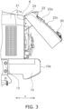
- FIG. 3 is a side view illustrating a state in which the grille 22 is rotated upward with respect to the main body part 21.
- the main body part 21 is provided so as to form side plates that covers the front and left and right sides of the engine disposed on the rear frame 12 and a top plate that covers the top of the engine. As shown in FIG. 3 , the rear end of the main body part 21 is provided with an opening 21a.
- the grille 22 is disposed so as to block the opening 21a at the rear end of the main body part 21.
- the grille 22 includes a grid-like part 22c on its rear surface, and as shown in FIGS. 2A and 2C , air for cooling the cooling water of the engine is discharged from the engine room 6 through the grille 22 to the outside..
- a hinge 24 is disposed between the top part of the rear end of the main body part 21 and the top part of the grille 22.
- the hinge 24 allows the grille 22 to rotate in the up-down direction around the upper part of the rear end of the main body part 21. By rotating the grille 22 upward, the fan and the like inside the engine room 6 can be cleaned.
- FIG. 4 is a partially enlarged view of the grille 22.
- Grille 22 includes a panel part 22a and a structural member 22b.
- the panel part 22a is made of resin and forms the outer surface, and the panel part 22a also includes a grid-like part 22c provided on the rear surface thereof.
- Structural member 22b is made of metal and is provided to support the panel part 22a.
- the structural member 22b is provided in a frame shape around the grid-like part 22c, and the hinge 24 described above is provided on the structural member 22b.
- the position of the grille 22 is located on the front direction Xf side than the rear end 10e of the counterweight 10.
- the radar devices 30 are disposed between the grille 22 and the rear end 10e in the front-rear direction X with a gap from each of the grille 22 and the counterweight 10.
- the radar device 30 detects the presence of an obstacle S in the rear of the vehicle body 1, as shown in FIG. 1 .
- the wheel loader 100 of this embodiment is provided with two radar devices 30.
- the radar devices 30 are disposed above the counterweight 10.
- the radar devices 30 are disposed on the lower part of the grille 22 and on the rear direction Xb side of the grille 22.
- FIG. 5 is a plan view illustrating the vicinity of two radar devices 30.
- the two radar devices 30 are disposed on the right side and the left side of the central axis A along the front-rear direction of the rear frame 12.
- the left-right direction is indicated by an arrow Y
- the left direction of the left-right direction Y is indicated by an arrow Yl
- the right direction is indicated by an arrow Yr.
- the plurality of radar devices 30 are disposed symmetrically with respect to the central axis A.
- the radar device 30 is, for example, a millimeter wave radar.
- the radar device 30 can measure the distance to an object by detecting, with the receiving antenna, the radio waves in the millimeter wave band which is emitted from the transmitting antenna and is returned after being reflected by the surface of the obstacle.
- a detection result by the radar device 30 is transmitted to a processor (not shown), and the processor can detect that an obstacle exists within a predetermined range when the wheel loader 100 is moving rearward.
- the transmitting antenna emits radio waves at a wider angle in the left-right direction than in the up- down direction.
- FIG. 6(a) is a perspective view of the vicinity of the radar device 30 as view from the rear.
- FIG. 6(b) is a view illustrating a state in which the cover part 31b is removed from the configuration shown in FIG. 6(a) .
- the radar device 30 includes a housing 31 and a detector 32. Housing 31 houses detector 32.
- the housing 31 includes a support part 31a that supports the detector 32 and a cover part 31b that covers the surface of the detector 32.
- the detector 32 is fixed to the surface of the support part 31a of the housing 31.
- Detector 32 is provided with a transmitting antenna and a receiving antenna.
- the detector 32 is attached to the support part 31a so that the detection surface 32a faces rearward. Note that the radar device 30 shown in FIGS. 2 to 5 described above is in a state in which the cover part 31b is removed.
- the cover part 31b is attached to the support part 31a so as to cover the detection surface 32a from the rear.
- Radar device 30 is fixed to grille 22. Therefore, as shown in FIG. 3 , when the grille 22 rotates upward with respect to the main body part 21, the radar device 30 also moves upward together with the grille 22.
- the radar device 30 is fixed to the grille 22 with a bracket 33.
- the bracket 33 is fixed to a structural member 22b, which is made of metal, of grille 22.
- the bracket 33 is fixed to the structural member 22b on the front side of the grid-like part 22c of the grille 22 (which can be said to be the inside of the engine room 6), and passes through the gap of the grid-like part 22c and supports the radar device 30 on the rear side of the grid-like part 22c.
- the bracket 33 is formed by bending one elongated plate member.
- the bracket 33 includes a first portion 33a, a second portion 33b, and a third portion 33c.
- the first portion 33a is fixed to the horizontal portion of the structural member 22b by bolts 35 on the front direction Xf side of the grid-like part 22c of the grille 22.
- the second portion 33b is formed upward from the rear end of the first portion 33a.
- the third portion 33c extends from the upper end of the second portion 33b to the rear direction Xb side through the gaps of the grid-like part 22c and is attached to the support part 31a on the rear side of the grille 22.
- Each detector 32 provided in the two radar devices 30 is installed so as to face outward from the direction parallel to the central axis A of the rear frame 12, as shown in FIG. 5 .
- the detector 32 of the radar device 30 disposed on the left direction Yl side of the central axis A is inclined with respect to the front-rear direction X so that the detection surface 32a faces the left direction Yl side of the vehicle body 1.
- the detector 32 of the radar device 30 disposed on the right direction Yr side of the central axis A is inclined with respect to the front-rear direction X so that the detection surface 32a faces the right direction Yr side of the vehicle body 1.
- the detector 32 of the radar device 30 disposed on the left direction Y1 side of the central axis A is disposed so that a vertical line B, which is perpendicular to the detection surface 32a and extending in the rear direction from the detection surface 32a, tilts toward the left direction Yl side from the direction parallel to the central axis A as it goes in the rear direction.
- the detector 32 of the radar device 30 disposed on the right direction Yr side of the central axis A is disposed so that a vertical line B, which is perpendicular to the detection surface 32a and extending in the rear direction from the detection surface 32a, tilts toward the right direction Yr side from the direction parallel to the central axis A as it goes in the rear direction.
- each of the plurality of detectors 32 is disposed such that the vertical line B, which is perpendicular to the detection surface 32a and extending in the rear direction from the detection surface 32a, tilts toward the outside of the vehicle body 1 from the direction parallel to the central axis A as it goes in the rear direction. This make it possible to widen the detection range in the width direction (left-right direction) at the rear of the vehicle body 1
- FIG. 7 is a view illustrating a state in which the wheel loader 100 is traveling in the rear direction while bending.
- the wheel loader 100 that has traveled in the rear direction is indicated by a two-dot chain line.
- the detection range of the radar device 30 in the left side is indicated by 30Dl
- the detection range of the radar device 30 in the right side is indicated by 30Dr.
- the detection range is indicated as 30D.
- each radar device 30 By disposing each radar device 30 so that the detector 32 faces outward as described above, an obstacle in a wide range in the left-right direction can be detected when the vehicle travels in the rear direction while bending.
- the inclination angle of the radar device 30 is set so as not to protrude in the rear direction from the rear end 10e of the counterweight 10.
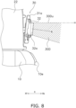
- FIG. 8 is a side view illustrating the vicinity of the radar device 30. As shown in FIG. 8 , the radar device 30 is disposed in the front side of the rear end 10e of the counterweight 10. Although the cover part 31b is not provided in FIG. 8 , even when the cover part 31b is combined with the support part 31a, the radar device 30 is disposed in the front side of the rear end 10e of the counterweight 10.
- the radar device 30 is disposed between the rear end 10e of the counterweight 10 and the grille 22 in the front-rear direction X.
- the radar device 30 is disposed with an outward inclination so as not to protrude in the rear direction from the counterweight 10.
- the radar device 30 is disposed so that the detection surface 32a of the detector 32 faces downward from the horizontal axis H. More specifically, as shown in FIG. 8 , the detectors 32 are disposed so that a vertical line B, which extends in the rear direction from the detection surface 32a of the detector 32 of each of the left and right radar devices 30 and is perpendicular to the detection surface 32a, faces downward from the horizontal axis H.
- the radar device 30 is installed so that the upper end 30Du of the up-down range in the detection range 30D of the detector 32 of the radar device 30 is parallel to the horizontal axis H.
- the obstacle occupies a certain range in the detection range in the up-down direction of the radar device. As shown in FIG. 1 , by installing the radar devices 30, an obstacle can be detected appropriately while ensuring a detectable distance from the rear end of the vehicle body 1.
- the left and right detection ranges behind the vehicle body 1 can be widened.
- the vehicle body 1 further includes a counterweight 10 disposed on the rear part of the rear frame 12.
- the radar devices 30 are installed in the front side of the rear end 10e of the counterweight 10.
- the radar device 30 is prevented from protruding behind the counterweight 10, and the overall length can be suppressed.
- the detector 32 is installed below the horizontal axis H of the rear frame 12.
- the radar device 30 In detection by the radar device 30, it is necessary that the obstacle occupies a certain range in the detection range in the up-down direction of the radar device 30. Therefore, by installing the radar devices 30 as described above, an obstacle can be detected appropriately while ensuring a detectable distance from the rear end of the vehicle body 1.
- the detector 32 is installed such that upper end 30Du of detection range 30D is along horizontal axis H.
- the obstacle can be detected appropriately while ensuring a detectable distance from the rear end of the vehicle body 1.
- the vehicle body 1 further includes an engine room 6 and a counterweight 10.
- the engine room 6 is disposed in the rear frame 12 and accommodates the engine.
- the counterweight 10 is disposed at the rear part of the rear frame 12.
- the engine room 6 includes a main body part 21 and a grille 22.
- the main body part 21 includes an opening 21a at its rear end.
- the grille 22 is disposed above the counterweight 10 so as to block the opening 21a of the main body part 21.
- a part of the counterweight 10 is disposed in the rear of the engine room 6.
- the radar devices 30 are attached to the grille 22.
- the radar devices 30 By attaching the radar devices 30 to the grille 22 in this manner, the radar devices 30 can be attached to the rear end of the vehicle body 1.
- radar devices 30 are attached to a structural member 22b, which is made of metal, of grille 22.
- the radar devices 30 can be stably disposed on the grille 22. Further, even when the grille 22 is rotatable with respect to the main body part 21, the radar devices 30 can be stably disposed by attaching them to the structural member 22b.
- the radar device 30 further includes a housing 31 that houses the detector 32.
- the detector 32 can be protected.
- the work machine is the wheel loader 100.
- the wheel loader 100 includes a work implement 3 and a cab 5.
- the work implement 3 is disposed in front of the front frame 11.
- the cab 5 is disposed in front of the engine room 6.
- the detection range in the left-right direction at the rear can be widened.
Landscapes
- Engineering & Computer Science (AREA)
- Mining & Mineral Resources (AREA)
- Civil Engineering (AREA)
- General Engineering & Computer Science (AREA)
- Structural Engineering (AREA)
- Remote Sensing (AREA)
- Radar, Positioning & Navigation (AREA)
- Physics & Mathematics (AREA)
- General Physics & Mathematics (AREA)
- Computer Networks & Wireless Communication (AREA)
- Mechanical Engineering (AREA)
- Electromagnetism (AREA)
- Radar Systems Or Details Thereof (AREA)
- Component Parts Of Construction Machinery (AREA)
Abstract
Description
- The present invention relates to a work machine.
- Collision suppression system has been proposed for detecting an obstacle to the rear and suppressing a collision in a work machine such as a wheel loader (for example, see Patent Document 1).
- In such a collision suppression system, a radar device or the like fixed to the rear end of the work machine detects an obstacle existing in the rear of the engine room that is difficult to see from the cab.
- Patent Document No. 1: Registration of Utility Model No.
3219005 - The above-mentioned fixed radar device has a limited detection range, while a vehicle having an articulated mechanism such as a wheel loader has a small turning radius, so, it is necessary to widen the detection range when turning. Therefore it was difficult to detect an obstacle appropriately.
- An object of the present disclosure is to provide a work machine capable of detecting an obstacle more appropriately.
- A work machine according to a disclosure comprise a vehicle body and a plurality of radar devices. The vehicle body includes a front frame and a rear frame. Traveling wheels are disposed on the front frame. Traveling wheels are disposed on the rear frame. The rear frame is relatively operably connected to the front frame with an articulated mechanism. The plurality of radar devices are positioned on a right side and a left side of a central axis along a front-rear direction of the rear frame and installed at a rear part of the vehicle body. Each radar device of the plurality of radar devices includes a detector configured to detect an object. The detector is disposed facing outward from a direction parallel to the central axis.
- According to the present disclosure, it is possible to provide a work machine capable of detecting an obstacle more appropriately.
-
-
FIG. 1 is a side illustrating a wheel loader of an embodiment according to the present disclosure. -
FIG. 2A is a rear view of the wheel loader ofFIG. 1 . -
FIG. 2B is a side view illustrating a rear part of the wheel loader inFIG. 1 . -
FIG. 2C is a perspective view illustrating the rear part of the wheel loader inFIG. 1 . -
FIG. 3 is a side view illustrating a state in which a grille is rotated upward with respect to the main body inFIG. 2A . -
FIG. 4 is a perspective cross-sectional view of the vicinity of radar devices inFIG. 2C . -
FIG. 5 is a plan view illustrating the radar devices inFIG. 4 as viewed from the top. -
FIG. 6(a) is a perspective view of the radar devices inFIG. 4 as viewed from the rear,FIG. 6(b) is a perspective view illustrating a state in which detectors are exposed from the radar devices inFIG. 6(a) . -
FIG. 7 is a plan view illustrating a state in which the wheel loader inFIG. 1 is bend. -
FIG. 8 is an enlarged view illustrating the vicinity of the radar devices inFIG. 2A . - Awheel loader as an example of a work machine according to the present disclosure will be described below with reference to the drawings.
-
FIG. 1 is a side view illustrating the wheel loader 100 (an example of a work machine) of present embodiment. - A
wheel loader 100 of present embodiment includes a vehicle body 1 and a plurality ofradar devices 30. The vehicle body 1 includes an articulated mechanism. A plurality ofradar devices 30 are disposed on the rear part of the vehicle body 1. - A vehicle body 1 includes a
vehicle body frame 2, a work implement 3, a pair of front tires 4 (an example of traveling wheels), acab 5, anengine room 6, a pair of rear tires 7 (an example of traveling wheels), and asteering cylinder 9, and acounterweight 10. - In the following description, "front", "rear", "right", "left", "up", and "down" indicate directions relative to a state of looking forward from the driver's seat. Also, "vehicle width direction" and "left-right direction" have the same meaning. In
FIG. 1 , the front-rear direction is indicated by X, the front direction is indicated by Xf, and the rear direction is indicated by Xb. - The
wheel loader 100 performs work such as earth and sand loading by using the work implement 3. - The
vehicle body frame 2 is a so-called articulated construction and includes afront frame 11, arear frame 12, and acoupling shaft part 13. Thefront frame 11 is disposed in front of therear frame 12. Thecoupling shaft part 13 is provided in the center in the vehicle width direction and couples thefront frame 11 and therear frame 12 to each other in a manner that allows swinging. The pair offront tires 4 are attached to the left and right of thefront frame 11. The pair ofrear tires 7 are attached to the left and right of therear frame 12. - The
work implement 3 is driven by hydraulic fluid from a work implement pump (not shown). Thework implement 3 is attached to the front part of thefront frame 11 in a manner that allows swinging. Thework implement 3 includes aboom 14, abucket 15, alift cylinder 16, abucket cylinder 17, and abell crank 18. - The base end of the
boom 14 is rotatably attached to a front part of thefront frame 11. The tip end of theboom 14 is rotatably attached to a rear part of thebucket 15. The rear part of thebucket 15 is on the opposite side from an opening 15b. The tip end of a cylinder rod of thelift cylinder 16 is rotatably attached between the base end and the tip end of theboom 14. The cylinder body of thelift cylinder 16 is rotatably attached to thefront frame 11. - One end part of the
bell crank 18 is rotatably attached to the tip end of a cylinder rod of thebucket cylinder 17. The other end part of the bell crank 18 is rotatably attached to a rear part of thebucket 15. Thebell crank 18 is rotatably supported by a bell cranksupport 14d near the middle of theboom 14 between either end. The cylinder body of thebucket cylinder 17 is rotatably attached to thefront frame 11. The extension/contraction force of thebucket cylinder 17 is converted to rotational movement by the bell crank 18 and is transmitted to thebucket 15. - The
bucket 15 is rotatably attached to the tip end of theboom 14 so as to open toward the front. By extending and contracting thebucket cylinder 17, thebucket 15 rotates with respect to theboom 14 and performs a tilting motion and a dumping motion. - The
cab 5 is disposed on therear frame 12. A steering handle for performing steering operations, a lever for operating the work implement 3, and various display devices are disposed inside thecab 5. Theengine room 6 is disposed to the rear of thecab 5 and on therear frame 12 and accommodates an engine (not shown). -
FIG. 2A is a side view illustrating the rear part.FIG. 2B is a rear view ofwheel loader 100.FIG. 2C is a perspective view illustrating the rear part ofwheel loader 100. - The
counterweight 10 is attached to the rear part of therear frame 12. Thecounterweight 10 is disposed so as to protrude rearward from below theengine room 6. A part of thecounterweight 10 is located in the rear of theengine room 6. Arear end 10e which is an end of thecounterweight 10 on the rear direction Xb side corresponds to the rear end of thewheel loader 100. - The
rear frame 12 is configured by combining frame members, thecab 5 is disposed above the front part of therear frame 12, and theengine room 6 is disposed above therear frame 12 in the rear of thecab 5. As shown inFIG. 2A , thecounterweight 10 is attached to the rear part of therear frame 12 and is disposed below the rear part of theengine room 6, and therear end 10e of thecounterweight 10 protrudes rearward beyond theengine room 6. - As shown in
FIGS. 2A to 2C , theengine room 6 includes amain body part 21 and agrille 22 that is rotatable with respect to themain body part 21.FIG. 3 is a side view illustrating a state in which thegrille 22 is rotated upward with respect to themain body part 21. - The
main body part 21 is provided so as to form side plates that covers the front and left and right sides of the engine disposed on therear frame 12 and a top plate that covers the top of the engine. As shown inFIG. 3 , the rear end of themain body part 21 is provided with anopening 21a. Thegrille 22 is disposed so as to block theopening 21a at the rear end of themain body part 21. Thegrille 22 includes a grid-like part 22c on its rear surface, and as shown inFIGS. 2A and2C , air for cooling the cooling water of the engine is discharged from theengine room 6 through thegrille 22 to the outside.. - As shown in
FIG. 3 , ahinge 24 is disposed between the top part of the rear end of themain body part 21 and the top part of thegrille 22. Thehinge 24 allows thegrille 22 to rotate in the up-down direction around the upper part of the rear end of themain body part 21. By rotating thegrille 22 upward, the fan and the like inside theengine room 6 can be cleaned. -
FIG. 4 is a partially enlarged view of thegrille 22.Grille 22 includes apanel part 22a and astructural member 22b. Thepanel part 22a is made of resin and forms the outer surface, and thepanel part 22a also includes a grid-like part 22c provided on the rear surface thereof.Structural member 22b is made of metal and is provided to support thepanel part 22a. Although not shown, thestructural member 22b is provided in a frame shape around the grid-like part 22c, and thehinge 24 described above is provided on thestructural member 22b. - As shown in
FIG. 2A , the position of thegrille 22 is located on the front direction Xf side than therear end 10e of thecounterweight 10. Theradar devices 30 are disposed between thegrille 22 and therear end 10e in the front-rear direction X with a gap from each of thegrille 22 and thecounterweight 10. - The
radar device 30 detects the presence of an obstacle S in the rear of the vehicle body 1, as shown inFIG. 1 . As shown inFIG. 2C , thewheel loader 100 of this embodiment is provided with tworadar devices 30. Theradar devices 30 are disposed above thecounterweight 10. As shown inFIG. 2A , theradar devices 30 are disposed on the lower part of thegrille 22 and on the rear direction Xb side of thegrille 22. -
FIG. 5 is a plan view illustrating the vicinity of tworadar devices 30. As shown inFIG. 5 , the tworadar devices 30 are disposed on the right side and the left side of the central axis A along the front-rear direction of therear frame 12. InFIG. 5 , the left-right direction is indicated by an arrow Y, the left direction of the left-right direction Y is indicated by an arrow Yl, and the right direction is indicated by an arrow Yr. As shown inFIGS. 2A and5 , in this embodiment, the plurality ofradar devices 30 are disposed symmetrically with respect to the central axis A. - The
radar device 30 is, for example, a millimeter wave radar. Theradar device 30 can measure the distance to an object by detecting, with the receiving antenna, the radio waves in the millimeter wave band which is emitted from the transmitting antenna and is returned after being reflected by the surface of the obstacle. A detection result by theradar device 30 is transmitted to a processor (not shown), and the processor can detect that an obstacle exists within a predetermined range when thewheel loader 100 is moving rearward. The transmitting antenna emits radio waves at a wider angle in the left-right direction than in the up- down direction. -
FIG. 6(a) is a perspective view of the vicinity of theradar device 30 as view from the rear.FIG. 6(b) is a view illustrating a state in which thecover part 31b is removed from the configuration shown inFIG. 6(a) . Theradar device 30 includes ahousing 31 and adetector 32.Housing 31houses detector 32. Thehousing 31 includes asupport part 31a that supports thedetector 32 and acover part 31b that covers the surface of thedetector 32. As shown inFIG. 6(b) , thedetector 32 is fixed to the surface of thesupport part 31a of thehousing 31.Detector 32 is provided with a transmitting antenna and a receiving antenna. Thedetector 32 is attached to thesupport part 31a so that thedetection surface 32a faces rearward. Note that theradar device 30 shown inFIGS. 2 to 5 described above is in a state in which thecover part 31b is removed. Thecover part 31b is attached to thesupport part 31a so as to cover thedetection surface 32a from the rear. -
Radar device 30 is fixed togrille 22. Therefore, as shown inFIG. 3 , when thegrille 22 rotates upward with respect to themain body part 21, theradar device 30 also moves upward together with thegrille 22. - As shown in
FIG. 4 , theradar device 30 is fixed to thegrille 22 with abracket 33. - The
bracket 33 is fixed to astructural member 22b, which is made of metal, ofgrille 22. For example, thebracket 33 is fixed to thestructural member 22b on the front side of the grid-like part 22c of the grille 22 (which can be said to be the inside of the engine room 6), and passes through the gap of the grid-like part 22c and supports theradar device 30 on the rear side of the grid-like part 22c. - For example, the
bracket 33 is formed by bending one elongated plate member. Thebracket 33 includes afirst portion 33a, asecond portion 33b, and athird portion 33c. - The
first portion 33a is fixed to the horizontal portion of thestructural member 22b bybolts 35 on the front direction Xf side of the grid-like part 22c of thegrille 22. Thesecond portion 33b is formed upward from the rear end of thefirst portion 33a. Thethird portion 33c extends from the upper end of thesecond portion 33b to the rear direction Xb side through the gaps of the grid-like part 22c and is attached to thesupport part 31a on the rear side of thegrille 22. - Each
detector 32 provided in the tworadar devices 30 is installed so as to face outward from the direction parallel to the central axis A of therear frame 12, as shown inFIG. 5 . - The
detector 32 of theradar device 30 disposed on the left direction Yl side of the central axis A is inclined with respect to the front-rear direction X so that thedetection surface 32a faces the left direction Yl side of the vehicle body 1. Thedetector 32 of theradar device 30 disposed on the right direction Yr side of the central axis A is inclined with respect to the front-rear direction X so that thedetection surface 32a faces the right direction Yr side of the vehicle body 1. - Specifically, the
detector 32 of theradar device 30 disposed on the left direction Y1 side of the central axis A is disposed so that a vertical line B, which is perpendicular to thedetection surface 32a and extending in the rear direction from thedetection surface 32a, tilts toward the left direction Yl side from the direction parallel to the central axis A as it goes in the rear direction. Thedetector 32 of theradar device 30 disposed on the right direction Yr side of the central axis A is disposed so that a vertical line B, which is perpendicular to thedetection surface 32a and extending in the rear direction from thedetection surface 32a, tilts toward the right direction Yr side from the direction parallel to the central axis A as it goes in the rear direction. - In this way, each of the plurality of
detectors 32 is disposed such that the vertical line B, which is perpendicular to thedetection surface 32a and extending in the rear direction from thedetection surface 32a, tilts toward the outside of the vehicle body 1 from the direction parallel to the central axis A as it goes in the rear direction. This make it possible to widen the detection range in the width direction (left-right direction) at the rear of the vehicle body 1 -
FIG. 7 is a view illustrating a state in which thewheel loader 100 is traveling in the rear direction while bending. InFIG. 7 , thewheel loader 100 that has traveled in the rear direction is indicated by a two-dot chain line. - In
FIG. 7 , the detection range of theradar device 30 in the left side is indicated by 30Dl, and the detection range of theradar device 30 in the right side is indicated by 30Dr. In addition, when it is not necessary to distinguish the detection range between the left side and rightside radar devices 30, the detection range is indicated as 30D. - By disposing each
radar device 30 so that thedetector 32 faces outward as described above, an obstacle in a wide range in the left-right direction can be detected when the vehicle travels in the rear direction while bending. - In addition, as shown in
FIG. 5 , the inclination angle of theradar device 30 is set so as not to protrude in the rear direction from therear end 10e of thecounterweight 10. -
FIG. 8 is a side view illustrating the vicinity of theradar device 30. As shown inFIG. 8 , theradar device 30 is disposed in the front side of therear end 10e of thecounterweight 10. Although thecover part 31b is not provided inFIG. 8 , even when thecover part 31b is combined with thesupport part 31a, theradar device 30 is disposed in the front side of therear end 10e of thecounterweight 10. - The
radar device 30 is disposed between therear end 10e of thecounterweight 10 and thegrille 22 in the front-rear direction X. Theradar device 30 is disposed with an outward inclination so as not to protrude in the rear direction from thecounterweight 10. - The
radar device 30 is disposed so that thedetection surface 32a of thedetector 32 faces downward from the horizontal axis H. More specifically, as shown inFIG. 8 , thedetectors 32 are disposed so that a vertical line B, which extends in the rear direction from thedetection surface 32a of thedetector 32 of each of the left andright radar devices 30 and is perpendicular to thedetection surface 32a, faces downward from the horizontal axis H. - Further, as shown in
FIG. 1 , theradar device 30 is installed so that the upper end 30Du of the up-down range in thedetection range 30D of thedetector 32 of theradar device 30 is parallel to the horizontal axis H. - In order to detect an obstacle, it is necessary that the obstacle occupies a certain range in the detection range in the up-down direction of the radar device. As shown in
FIG. 1 , by installing theradar devices 30, an obstacle can be detected appropriately while ensuring a detectable distance from the rear end of the vehicle body 1. -
- (1) A wheel loader 100 (an example of a work machine) of the present embodiment includes a vehicle body 1 and a plurality of
radar devices 30. The vehicle body 1 includes afront frame 11 and arear frame 12. Front tires 4 (an example of traveling wheels) are disposed on thefront frame 11. Rear tires 7 (an example of traveling wheels) are disposed on therear frame 12. Therear frame 12 is relatively operably connected to thefront frame 11 by an articulated mechanism. The plurality ofradar devices 30 are positioned on right and left sides of the central axis A along the front-rear direction of therear frame 12 and installed in the rear part of the vehicle body 1. Theradar device 30 includes adetector 32 that detects an obstacle S (an example of an object). Thedetector 32 is installed facing outward from the direction parallel to the central axis A. - By providing a plurality of
radar devices 30 in this way, it is possible to widen the detection range in the left-right direction. Therefore, as shown inFIG. 7 , it is possible to more properly detect an obstacle even when the vehicle travels in the rear direction while turning. - In addition, by installing the
detector 32 toward the outside of the direction parallel to the central axis A, the left and right detection ranges behind the vehicle body 1 can be widened. - (2) In the wheel loader 100 (an example of a work machine) of the present embodiment, the vehicle body 1 further includes a
counterweight 10 disposed on the rear part of therear frame 12. Theradar devices 30 are installed in the front side of therear end 10e of thecounterweight 10. - As a result, the
radar device 30 is prevented from protruding behind thecounterweight 10, and the overall length can be suppressed. - (3) In the wheel loader 100 (an example of a work machine) of the present embodiment, the
detector 32 is installed below the horizontal axis H of therear frame 12. - In detection by the
radar device 30, it is necessary that the obstacle occupies a certain range in the detection range in the up-down direction of theradar device 30. Therefore, by installing theradar devices 30 as described above, an obstacle can be detected appropriately while ensuring a detectable distance from the rear end of the vehicle body 1. - (4) In wheel loader 100 (an example of a work machine) of the present embodiment, the
detector 32 is installed such that upper end 30Du ofdetection range 30D is along horizontal axis H. - As a result, the obstacle can be detected appropriately while ensuring a detectable distance from the rear end of the vehicle body 1.
- (5) In the wheel loader 100 (an example of a work machine) of the present embodiment, the vehicle body 1 further includes an
engine room 6 and acounterweight 10. Theengine room 6 is disposed in therear frame 12 and accommodates the engine. Thecounterweight 10 is disposed at the rear part of therear frame 12. Theengine room 6 includes amain body part 21 and agrille 22. Themain body part 21 includes anopening 21a at its rear end. Thegrille 22 is disposed above thecounterweight 10 so as to block theopening 21a of themain body part 21. A part of thecounterweight 10 is disposed in the rear of theengine room 6. Theradar devices 30 are attached to thegrille 22. - By attaching the
radar devices 30 to thegrille 22 in this manner, theradar devices 30 can be attached to the rear end of the vehicle body 1. - (6) In wheel loader 100 (an example of a work machine) of the present embodiment,
radar devices 30 are attached to astructural member 22b, which is made of metal, ofgrille 22. - Thereby, the
radar devices 30 can be stably disposed on thegrille 22. Further, even when thegrille 22 is rotatable with respect to themain body part 21, theradar devices 30 can be stably disposed by attaching them to thestructural member 22b. - (7) In the wheel loader 100 (an example of a work machine) of the present embodiment, the
radar device 30 further includes ahousing 31 that houses thedetector 32. - Thereby, the
detector 32 can be protected. - (8) In this embodiment, the work machine is the
wheel loader 100. Thewheel loader 100 includes a work implement 3 and acab 5. The work implement 3 is disposed in front of thefront frame 11. Thecab 5 is disposed in front of theengine room 6. - As a result, in the
wheel loader 100, the detection range in the left-right direction at the rear can be widened. - Although one embodiment of the present invention has been described above, the present invention is not limited to the above-described embodiment, and various modifications are possible without departing from the gist of the invention.
- (A) In the above embodiment, two
radar devices 30 are provided, but three ormore radar devices 30 may be provided in the width direction (left-right horizontal direction Y). - (B) One or a plurality of
radar devices 30 may be disposed above or below oneradar device 30 provided on the left side of the central axis A. Further, one or a plurality ofradar devices 30 may be arranged above or below oneradar device 30 provided on the right side of the central axis A. - (C) In the above-described embodiment, the plurality of
radar devices 30 are disposed symmetrically with respect to the central axis A, but they may not be disposed symmetrically. - (D) The
radar devices 30 are fixed to thestructural member 22b of thegrille 22 in the above embodiment, but are not limited to this and may be attached to thecounterweight 10, for example. When theradar devices 30 are attached to thecounterweight 10, theradar devices 30 are not limited to being attached to the surface of thecounterweight 10, and may be embedded. - (E) In the above-described embodiment, the
grille 22 is provided so as to be rotatable upward with respect to themain body part 21, but it may be provided so as to be rotatable not only upwardly, but also to the left or right, for example. - (F) Although the
radar devices 30 are fixed to thestructural member 22b, which is made of metal, of thegrille 22 in the above embodiment, theradar devices 30 may be attached to the grid-like part 22c when the grid-like part 22c is made of metal. - (G) In the above embodiment, a wheel loader is used as an example of a work machine, but a dump truck, motor grader, or the like including an articulated mechanism may also be used.
- According to the work machine of the present disclosure, it is possible to detect an obstacle more appropriately.
-
- 10: Counterweight
- 11: Front frame
- 12: Rear frame
- 30: Radar device
- 100: Wheel loader
Claims (8)
- A work machine comprising:a vehicle body including a front frame and a rear frame, traveling wheels being disposed on the front frame, traveling wheels being disposed the rear frame, the rear frame being relatively operably connected to the front frame by an articulated mechanism; anda plurality of radar devices positioned on right and left sides of a central axis along a front-rear direction of the rear frame, the plurality of radar devices being installed at a rear part of the vehicle body, whereineach radar device of the plurality of radar devices includes a detector configured to detect an object, andthe detector is installed facing outward from a direction parallel to the central axis.
- The work machine according to claim 1, whereinthe vehicle body further includes a counterweight disposed at a rear part of the rear frame, andthe radar device is installed forward of a rear end of the counterweight.
- The work machine according to claim 1, wherein
the detector is installed downward from a horizontal axis of the rear frame. - The work machine according to claim 3, wherein
the detector is installed such that an upper end of detection range is along the horizontal axis. - The work machine according to claim 1, whereinthe vehicle body further includesan engine room disposed in the rear frame and housing an engine anda counterweight disposed at a rear part of the rear frame, andthe engine room includesa main body part including an opening at rear end thereof anda grille disposed above the counterweight so as to block the opening of the main body part, anda part of the counterweight is located behind the engine room, andthe radar devices are attached to the grille.
- The work machine according to claim 5, wherein
the radar devices are attached to a structural member, which is made of metal, of the grille. - The work machine according to claim 1, wherein
the radar device further includes a housing that houses the detector. - The work machine according to claim 5, further comprisinga work implement disposed in front of the front frame, anda cab disposed in front of the engine room, whereinthe work machine is a wheel loader.
Applications Claiming Priority (2)
| Application Number | Priority Date | Filing Date | Title |
|---|---|---|---|
| JP2020165734A JP7523305B2 (en) | 2020-09-30 | 2020-09-30 | Work Machine |
| PCT/JP2021/027032 WO2022070562A1 (en) | 2020-09-30 | 2021-07-19 | Work machine |
Publications (2)
| Publication Number | Publication Date |
|---|---|
| EP4151805A1 true EP4151805A1 (en) | 2023-03-22 |
| EP4151805A4 EP4151805A4 (en) | 2024-08-07 |
Family
ID=80949830
Family Applications (1)
| Application Number | Title | Priority Date | Filing Date |
|---|---|---|---|
| EP21874866.3A Pending EP4151805A4 (en) | 2020-09-30 | 2021-07-19 | WORKING MACHINE |
Country Status (5)
| Country | Link |
|---|---|
| US (1) | US12460387B2 (en) |
| EP (1) | EP4151805A4 (en) |
| JP (1) | JP7523305B2 (en) |
| CN (1) | CN115702279A (en) |
| WO (1) | WO2022070562A1 (en) |
Family Cites Families (7)
| Publication number | Priority date | Publication date | Assignee | Title |
|---|---|---|---|---|
| GB980651A (en) | 1962-08-29 | 1965-01-13 | Harland Engineering Co Ltd | Automatic hovering gear for submarines |
| JP6232370B2 (en) * | 2014-12-24 | 2017-11-15 | 株式会社Kcm | Construction machinery |
| US10815640B2 (en) | 2016-08-31 | 2020-10-27 | Komatsu Ltd. | Wheel loader and method for controlling wheel loader |
| CN108633293B (en) * | 2017-02-09 | 2022-02-25 | 株式会社小松制作所 | Work vehicle and display device |
| JP6824126B2 (en) | 2017-08-08 | 2021-02-03 | 大林道路株式会社 | Anti-collision device when moving backwards in construction machinery |
| JP6757759B2 (en) | 2018-03-20 | 2020-09-23 | 日立建機株式会社 | Work vehicle |
| JP3219005U (en) | 2018-09-10 | 2018-11-22 | 大成ロテック株式会社 | Construction vehicle |
-
2020
- 2020-09-30 JP JP2020165734A patent/JP7523305B2/en active Active
-
2021
- 2021-07-19 WO PCT/JP2021/027032 patent/WO2022070562A1/en not_active Ceased
- 2021-07-19 EP EP21874866.3A patent/EP4151805A4/en active Pending
- 2021-07-19 CN CN202180043205.6A patent/CN115702279A/en active Pending
- 2021-07-19 US US18/004,406 patent/US12460387B2/en active Active
Also Published As
| Publication number | Publication date |
|---|---|
| JP2022057460A (en) | 2022-04-11 |
| US12460387B2 (en) | 2025-11-04 |
| WO2022070562A1 (en) | 2022-04-07 |
| EP4151805A4 (en) | 2024-08-07 |
| US20230295900A1 (en) | 2023-09-21 |
| JP7523305B2 (en) | 2024-07-26 |
| CN115702279A (en) | 2023-02-14 |
Similar Documents
| Publication | Publication Date | Title |
|---|---|---|
| JP6216097B2 (en) | Work machine periphery monitoring device | |
| JP7804600B2 (en) | Rotating work vehicle | |
| JP2022000571A (en) | Construction machine | |
| JP2008303648A (en) | Work machine warning system | |
| JP6757759B2 (en) | Work vehicle | |
| US20230257967A1 (en) | Revolving work vehicle, and method for detecting position of working end of revolving work vehicle | |
| US20210363732A1 (en) | System and method for selectively displaying image data in a working machine | |
| CN116829789A (en) | Construction machinery | |
| US20170321392A1 (en) | Work vehicle | |
| JP7374602B2 (en) | work vehicle | |
| EP4624681A1 (en) | Rear safety system for construction equipment | |
| US12460387B2 (en) | Work machine | |
| CN116324095A (en) | Work vehicle | |
| KR20260053065A (en) | Construction machine, antenna attachment method, and antenna attachment structure | |
| CN104093913B (en) | Motor-driven grader | |
| CN205484774U (en) | Radar sensor assembly for a machine | |
| JP7341096B2 (en) | work vehicle | |
| JP7747563B2 (en) | Work vehicles | |
| US20240401301A1 (en) | Work vehicle | |
| JP7523703B2 (en) | Work vehicles | |
| WO1996015009A1 (en) | Safety arrangement | |
| JP7129388B2 (en) | work vehicle | |
| JP2024106742A (en) | Swivel work vehicle | |
| JP6172803B2 (en) | Dump vehicle | |
| CN117940792A (en) | Detection equipment and operating machinery |
Legal Events
| Date | Code | Title | Description |
|---|---|---|---|
| STAA | Information on the status of an ep patent application or granted ep patent |
Free format text: STATUS: THE INTERNATIONAL PUBLICATION HAS BEEN MADE |
|
| PUAI | Public reference made under article 153(3) epc to a published international application that has entered the european phase |
Free format text: ORIGINAL CODE: 0009012 |
|
| STAA | Information on the status of an ep patent application or granted ep patent |
Free format text: STATUS: REQUEST FOR EXAMINATION WAS MADE |
|
| 17P | Request for examination filed |
Effective date: 20221215 |
|
| AK | Designated contracting states |
Kind code of ref document: A1 Designated state(s): AL AT BE BG CH CY CZ DE DK EE ES FI FR GB GR HR HU IE IS IT LI LT LU LV MC MK MT NL NO PL PT RO RS SE SI SK SM TR |
|
| DAV | Request for validation of the european patent (deleted) | ||
| DAX | Request for extension of the european patent (deleted) | ||
| A4 | Supplementary search report drawn up and despatched |
Effective date: 20240705 |
|
| RIC1 | Information provided on ipc code assigned before grant |
Ipc: E02F 9/26 20060101ALI20240701BHEP Ipc: E02F 9/08 20060101ALI20240701BHEP Ipc: E02F 9/24 20060101AFI20240701BHEP |
|
| STAA | Information on the status of an ep patent application or granted ep patent |
Free format text: STATUS: EXAMINATION IS IN PROGRESS |
|
| 17Q | First examination report despatched |
Effective date: 20260303 |