EP4151765A1 - Alloy member, process for producing said alloy member, and product including said alloy member - Google Patents
Alloy member, process for producing said alloy member, and product including said alloy member Download PDFInfo
- Publication number
- EP4151765A1 EP4151765A1 EP22198820.7A EP22198820A EP4151765A1 EP 4151765 A1 EP4151765 A1 EP 4151765A1 EP 22198820 A EP22198820 A EP 22198820A EP 4151765 A1 EP4151765 A1 EP 4151765A1
- Authority
- EP
- European Patent Office
- Prior art keywords
- atomic
- less
- alloy
- hea
- alloy member
- Prior art date
- Legal status (The legal status is an assumption and is not a legal conclusion. Google has not performed a legal analysis and makes no representation as to the accuracy of the status listed.)
- Pending
Links
Images




Classifications
-
- C—CHEMISTRY; METALLURGY
- C22—METALLURGY; FERROUS OR NON-FERROUS ALLOYS; TREATMENT OF ALLOYS OR NON-FERROUS METALS
- C22C—ALLOYS
- C22C30/00—Alloys containing less than 50% by weight of each constituent
-
- B—PERFORMING OPERATIONS; TRANSPORTING
- B22—CASTING; POWDER METALLURGY
- B22F—WORKING METALLIC POWDER; MANUFACTURE OF ARTICLES FROM METALLIC POWDER; MAKING METALLIC POWDER; APPARATUS OR DEVICES SPECIALLY ADAPTED FOR METALLIC POWDER
- B22F1/00—Metallic powder; Treatment of metallic powder, e.g. to facilitate working or to improve properties
-
- B—PERFORMING OPERATIONS; TRANSPORTING
- B22—CASTING; POWDER METALLURGY
- B22F—WORKING METALLIC POWDER; MANUFACTURE OF ARTICLES FROM METALLIC POWDER; MAKING METALLIC POWDER; APPARATUS OR DEVICES SPECIALLY ADAPTED FOR METALLIC POWDER
- B22F10/00—Additive manufacturing of workpieces or articles from metallic powder
- B22F10/60—Treatment of workpieces or articles after build-up
- B22F10/64—Treatment of workpieces or articles after build-up by thermal means
-
- B—PERFORMING OPERATIONS; TRANSPORTING
- B22—CASTING; POWDER METALLURGY
- B22F—WORKING METALLIC POWDER; MANUFACTURE OF ARTICLES FROM METALLIC POWDER; MAKING METALLIC POWDER; APPARATUS OR DEVICES SPECIALLY ADAPTED FOR METALLIC POWDER
- B22F3/00—Manufacture of workpieces or articles from metallic powder characterised by the manner of compacting or sintering; Apparatus specially adapted therefor ; Presses and furnaces
- B22F3/10—Sintering only
- B22F3/105—Sintering only by using electric current other than for infrared radiant energy, laser radiation or plasma ; by ultrasonic bonding
-
- B—PERFORMING OPERATIONS; TRANSPORTING
- B22—CASTING; POWDER METALLURGY
- B22F—WORKING METALLIC POWDER; MANUFACTURE OF ARTICLES FROM METALLIC POWDER; MAKING METALLIC POWDER; APPARATUS OR DEVICES SPECIALLY ADAPTED FOR METALLIC POWDER
- B22F3/00—Manufacture of workpieces or articles from metallic powder characterised by the manner of compacting or sintering; Apparatus specially adapted therefor ; Presses and furnaces
- B22F3/12—Both compacting and sintering
- B22F3/16—Both compacting and sintering in successive or repeated steps
-
- B—PERFORMING OPERATIONS; TRANSPORTING
- B22—CASTING; POWDER METALLURGY
- B22F—WORKING METALLIC POWDER; MANUFACTURE OF ARTICLES FROM METALLIC POWDER; MAKING METALLIC POWDER; APPARATUS OR DEVICES SPECIALLY ADAPTED FOR METALLIC POWDER
- B22F5/00—Manufacture of workpieces or articles from metallic powder characterised by the special shape of the product
- B22F5/08—Manufacture of workpieces or articles from metallic powder characterised by the special shape of the product of toothed articles, e.g. gear wheels; of cam discs
-
- B—PERFORMING OPERATIONS; TRANSPORTING
- B22—CASTING; POWDER METALLURGY
- B22F—WORKING METALLIC POWDER; MANUFACTURE OF ARTICLES FROM METALLIC POWDER; MAKING METALLIC POWDER; APPARATUS OR DEVICES SPECIALLY ADAPTED FOR METALLIC POWDER
- B22F9/00—Making metallic powder or suspensions thereof
- B22F9/02—Making metallic powder or suspensions thereof using physical processes
- B22F9/06—Making metallic powder or suspensions thereof using physical processes starting from liquid material
- B22F9/08—Making metallic powder or suspensions thereof using physical processes starting from liquid material by casting, e.g. through sieves or in water, by atomising or spraying
-
- B—PERFORMING OPERATIONS; TRANSPORTING
- B22—CASTING; POWDER METALLURGY
- B22F—WORKING METALLIC POWDER; MANUFACTURE OF ARTICLES FROM METALLIC POWDER; MAKING METALLIC POWDER; APPARATUS OR DEVICES SPECIALLY ADAPTED FOR METALLIC POWDER
- B22F9/00—Making metallic powder or suspensions thereof
- B22F9/02—Making metallic powder or suspensions thereof using physical processes
- B22F9/06—Making metallic powder or suspensions thereof using physical processes starting from liquid material
- B22F9/08—Making metallic powder or suspensions thereof using physical processes starting from liquid material by casting, e.g. through sieves or in water, by atomising or spraying
- B22F9/082—Making metallic powder or suspensions thereof using physical processes starting from liquid material by casting, e.g. through sieves or in water, by atomising or spraying atomising using a fluid
-
- B—PERFORMING OPERATIONS; TRANSPORTING
- B22—CASTING; POWDER METALLURGY
- B22F—WORKING METALLIC POWDER; MANUFACTURE OF ARTICLES FROM METALLIC POWDER; MAKING METALLIC POWDER; APPARATUS OR DEVICES SPECIALLY ADAPTED FOR METALLIC POWDER
- B22F9/00—Making metallic powder or suspensions thereof
- B22F9/02—Making metallic powder or suspensions thereof using physical processes
- B22F9/06—Making metallic powder or suspensions thereof using physical processes starting from liquid material
- B22F9/08—Making metallic powder or suspensions thereof using physical processes starting from liquid material by casting, e.g. through sieves or in water, by atomising or spraying
- B22F9/10—Making metallic powder or suspensions thereof using physical processes starting from liquid material by casting, e.g. through sieves or in water, by atomising or spraying using centrifugal force
-
- B—PERFORMING OPERATIONS; TRANSPORTING
- B33—ADDITIVE MANUFACTURING TECHNOLOGY
- B33Y—ADDITIVE MANUFACTURING, i.e. MANUFACTURING OF THREE-DIMENSIONAL [3D] OBJECTS BY ADDITIVE DEPOSITION, ADDITIVE AGGLOMERATION OR ADDITIVE LAYERING, e.g. BY 3D PRINTING, STEREOLITHOGRAPHY OR SELECTIVE LASER SINTERING
- B33Y10/00—Processes of additive manufacturing
-
- B—PERFORMING OPERATIONS; TRANSPORTING
- B33—ADDITIVE MANUFACTURING TECHNOLOGY
- B33Y—ADDITIVE MANUFACTURING, i.e. MANUFACTURING OF THREE-DIMENSIONAL [3D] OBJECTS BY ADDITIVE DEPOSITION, ADDITIVE AGGLOMERATION OR ADDITIVE LAYERING, e.g. BY 3D PRINTING, STEREOLITHOGRAPHY OR SELECTIVE LASER SINTERING
- B33Y40/00—Auxiliary operations or equipment, e.g. for material handling
- B33Y40/20—Post-treatment, e.g. curing, coating or polishing
-
- B—PERFORMING OPERATIONS; TRANSPORTING
- B33—ADDITIVE MANUFACTURING TECHNOLOGY
- B33Y—ADDITIVE MANUFACTURING, i.e. MANUFACTURING OF THREE-DIMENSIONAL [3D] OBJECTS BY ADDITIVE DEPOSITION, ADDITIVE AGGLOMERATION OR ADDITIVE LAYERING, e.g. BY 3D PRINTING, STEREOLITHOGRAPHY OR SELECTIVE LASER SINTERING
- B33Y70/00—Materials specially adapted for additive manufacturing
-
- B—PERFORMING OPERATIONS; TRANSPORTING
- B33—ADDITIVE MANUFACTURING TECHNOLOGY
- B33Y—ADDITIVE MANUFACTURING, i.e. MANUFACTURING OF THREE-DIMENSIONAL [3D] OBJECTS BY ADDITIVE DEPOSITION, ADDITIVE AGGLOMERATION OR ADDITIVE LAYERING, e.g. BY 3D PRINTING, STEREOLITHOGRAPHY OR SELECTIVE LASER SINTERING
- B33Y80/00—Products made by additive manufacturing
-
- C—CHEMISTRY; METALLURGY
- C22—METALLURGY; FERROUS OR NON-FERROUS ALLOYS; TREATMENT OF ALLOYS OR NON-FERROUS METALS
- C22C—ALLOYS
- C22C19/00—Alloys based on nickel or cobalt
- C22C19/03—Alloys based on nickel or cobalt based on nickel
- C22C19/05—Alloys based on nickel or cobalt based on nickel with chromium
- C22C19/051—Alloys based on nickel or cobalt based on nickel with chromium and Mo or W
- C22C19/056—Alloys based on nickel or cobalt based on nickel with chromium and Mo or W with the maximum Cr content being at least 10% but less than 20%
-
- C—CHEMISTRY; METALLURGY
- C22—METALLURGY; FERROUS OR NON-FERROUS ALLOYS; TREATMENT OF ALLOYS OR NON-FERROUS METALS
- C22C—ALLOYS
- C22C19/00—Alloys based on nickel or cobalt
- C22C19/07—Alloys based on nickel or cobalt based on cobalt
-
- C—CHEMISTRY; METALLURGY
- C22—METALLURGY; FERROUS OR NON-FERROUS ALLOYS; TREATMENT OF ALLOYS OR NON-FERROUS METALS
- C22C—ALLOYS
- C22C33/00—Making ferrous alloys
- C22C33/02—Making ferrous alloys by powder metallurgy
-
- C—CHEMISTRY; METALLURGY
- C22—METALLURGY; FERROUS OR NON-FERROUS ALLOYS; TREATMENT OF ALLOYS OR NON-FERROUS METALS
- C22F—CHANGING THE PHYSICAL STRUCTURE OF NON-FERROUS METALS AND NON-FERROUS ALLOYS
- C22F1/00—Changing the physical structure of non-ferrous metals or alloys by heat treatment or by hot or cold working
- C22F1/10—Changing the physical structure of non-ferrous metals or alloys by heat treatment or by hot or cold working of nickel or cobalt or alloys based thereon
-
- F—MECHANICAL ENGINEERING; LIGHTING; HEATING; WEAPONS; BLASTING
- F04—POSITIVE - DISPLACEMENT MACHINES FOR LIQUIDS; PUMPS FOR LIQUIDS OR ELASTIC FLUIDS
- F04D—NON-POSITIVE-DISPLACEMENT PUMPS
- F04D29/00—Details, component parts, or accessories
- F04D29/02—Selection of particular materials
- F04D29/023—Selection of particular materials especially adapted for elastic fluid pumps
-
- F—MECHANICAL ENGINEERING; LIGHTING; HEATING; WEAPONS; BLASTING
- F04—POSITIVE - DISPLACEMENT MACHINES FOR LIQUIDS; PUMPS FOR LIQUIDS OR ELASTIC FLUIDS
- F04D—NON-POSITIVE-DISPLACEMENT PUMPS
- F04D29/00—Details, component parts, or accessories
- F04D29/26—Rotors specially for elastic fluids
- F04D29/28—Rotors specially for elastic fluids for centrifugal or helico-centrifugal pumps for radial-flow or helico-centrifugal pumps
- F04D29/284—Rotors specially for elastic fluids for centrifugal or helico-centrifugal pumps for radial-flow or helico-centrifugal pumps for compressors
-
- B—PERFORMING OPERATIONS; TRANSPORTING
- B22—CASTING; POWDER METALLURGY
- B22F—WORKING METALLIC POWDER; MANUFACTURE OF ARTICLES FROM METALLIC POWDER; MAKING METALLIC POWDER; APPARATUS OR DEVICES SPECIALLY ADAPTED FOR METALLIC POWDER
- B22F10/00—Additive manufacturing of workpieces or articles from metallic powder
- B22F10/20—Direct sintering or melting
- B22F10/28—Powder bed fusion, e.g. selective laser melting [SLM] or electron beam melting [EBM]
-
- B—PERFORMING OPERATIONS; TRANSPORTING
- B22—CASTING; POWDER METALLURGY
- B22F—WORKING METALLIC POWDER; MANUFACTURE OF ARTICLES FROM METALLIC POWDER; MAKING METALLIC POWDER; APPARATUS OR DEVICES SPECIALLY ADAPTED FOR METALLIC POWDER
- B22F9/00—Making metallic powder or suspensions thereof
- B22F9/02—Making metallic powder or suspensions thereof using physical processes
- B22F9/06—Making metallic powder or suspensions thereof using physical processes starting from liquid material
- B22F9/08—Making metallic powder or suspensions thereof using physical processes starting from liquid material by casting, e.g. through sieves or in water, by atomising or spraying
- B22F9/082—Making metallic powder or suspensions thereof using physical processes starting from liquid material by casting, e.g. through sieves or in water, by atomising or spraying atomising using a fluid
- B22F2009/0848—Melting process before atomisation
-
- B—PERFORMING OPERATIONS; TRANSPORTING
- B22—CASTING; POWDER METALLURGY
- B22F—WORKING METALLIC POWDER; MANUFACTURE OF ARTICLES FROM METALLIC POWDER; MAKING METALLIC POWDER; APPARATUS OR DEVICES SPECIALLY ADAPTED FOR METALLIC POWDER
- B22F2301/00—Metallic composition of the powder or its coating
- B22F2301/15—Nickel or cobalt
-
- B—PERFORMING OPERATIONS; TRANSPORTING
- B22—CASTING; POWDER METALLURGY
- B22F—WORKING METALLIC POWDER; MANUFACTURE OF ARTICLES FROM METALLIC POWDER; MAKING METALLIC POWDER; APPARATUS OR DEVICES SPECIALLY ADAPTED FOR METALLIC POWDER
- B22F2301/00—Metallic composition of the powder or its coating
- B22F2301/20—Refractory metals
- B22F2301/205—Titanium, zirconium or hafnium
-
- B—PERFORMING OPERATIONS; TRANSPORTING
- B22—CASTING; POWDER METALLURGY
- B22F—WORKING METALLIC POWDER; MANUFACTURE OF ARTICLES FROM METALLIC POWDER; MAKING METALLIC POWDER; APPARATUS OR DEVICES SPECIALLY ADAPTED FOR METALLIC POWDER
- B22F2301/00—Metallic composition of the powder or its coating
- B22F2301/35—Iron
-
- B—PERFORMING OPERATIONS; TRANSPORTING
- B22—CASTING; POWDER METALLURGY
- B22F—WORKING METALLIC POWDER; MANUFACTURE OF ARTICLES FROM METALLIC POWDER; MAKING METALLIC POWDER; APPARATUS OR DEVICES SPECIALLY ADAPTED FOR METALLIC POWDER
- B22F2998/00—Supplementary information concerning processes or compositions relating to powder metallurgy
- B22F2998/10—Processes characterised by the sequence of their steps
-
- F—MECHANICAL ENGINEERING; LIGHTING; HEATING; WEAPONS; BLASTING
- F05—INDEXING SCHEMES RELATING TO ENGINES OR PUMPS IN VARIOUS SUBCLASSES OF CLASSES F01-F04
- F05D—INDEXING SCHEME FOR ASPECTS RELATING TO NON-POSITIVE-DISPLACEMENT MACHINES OR ENGINES, GAS-TURBINES OR JET-PROPULSION PLANTS
- F05D2230/00—Manufacture
- F05D2230/20—Manufacture essentially without removing material
- F05D2230/22—Manufacture essentially without removing material by sintering
-
- F—MECHANICAL ENGINEERING; LIGHTING; HEATING; WEAPONS; BLASTING
- F05—INDEXING SCHEMES RELATING TO ENGINES OR PUMPS IN VARIOUS SUBCLASSES OF CLASSES F01-F04
- F05D—INDEXING SCHEME FOR ASPECTS RELATING TO NON-POSITIVE-DISPLACEMENT MACHINES OR ENGINES, GAS-TURBINES OR JET-PROPULSION PLANTS
- F05D2230/00—Manufacture
- F05D2230/40—Heat treatment
-
- F—MECHANICAL ENGINEERING; LIGHTING; HEATING; WEAPONS; BLASTING
- F05—INDEXING SCHEMES RELATING TO ENGINES OR PUMPS IN VARIOUS SUBCLASSES OF CLASSES F01-F04
- F05D—INDEXING SCHEME FOR ASPECTS RELATING TO NON-POSITIVE-DISPLACEMENT MACHINES OR ENGINES, GAS-TURBINES OR JET-PROPULSION PLANTS
- F05D2300/00—Materials; Properties thereof
- F05D2300/10—Metals, alloys or intermetallic compounds
- F05D2300/17—Alloys
-
- F—MECHANICAL ENGINEERING; LIGHTING; HEATING; WEAPONS; BLASTING
- F05—INDEXING SCHEMES RELATING TO ENGINES OR PUMPS IN VARIOUS SUBCLASSES OF CLASSES F01-F04
- F05D—INDEXING SCHEME FOR ASPECTS RELATING TO NON-POSITIVE-DISPLACEMENT MACHINES OR ENGINES, GAS-TURBINES OR JET-PROPULSION PLANTS
- F05D2300/00—Materials; Properties thereof
- F05D2300/10—Metals, alloys or intermetallic compounds
- F05D2300/17—Alloys
- F05D2300/171—Steel alloys
-
- Y—GENERAL TAGGING OF NEW TECHNOLOGICAL DEVELOPMENTS; GENERAL TAGGING OF CROSS-SECTIONAL TECHNOLOGIES SPANNING OVER SEVERAL SECTIONS OF THE IPC; TECHNICAL SUBJECTS COVERED BY FORMER USPC CROSS-REFERENCE ART COLLECTIONS [XRACs] AND DIGESTS
- Y02—TECHNOLOGIES OR APPLICATIONS FOR MITIGATION OR ADAPTATION AGAINST CLIMATE CHANGE
- Y02P—CLIMATE CHANGE MITIGATION TECHNOLOGIES IN THE PRODUCTION OR PROCESSING OF GOODS
- Y02P10/00—Technologies related to metal processing
- Y02P10/25—Process efficiency
Definitions
- the present invention relates to an alloy member produced by a powder additive manufacturing process using a high entropy alloy, a process for producing the alloy member, and a product including the alloy member.
- High Entropy alloy (High Entropy Alloy: HEA) has been proposed.
- HEA is defined as an alloy composed of five or more main metal elements (5 to 35 atomic% each), and it is known that the following characteristics are exerted.
- Examples of the characteristics include (a) stabilization of the mixing condition due to the negative increase in the mixing entropy term in Gibbs' free energy formula; (b) diffusion delay due to complicated microstructure; (c) high hardness and reduction in temperature dependence of mechanical properties caused by high lattice distortion due to difference in size of constituent atoms; and (d) improvement of corrosion resistance by combined effect (also called cocktail effect) due to coexistence of various elements.
- Patent Literature 1 JP Patent Publication (Kokai) No. 2002-173732 discloses a high-entropy multicomponent alloy obtained by casting or synthesizing a plurality of metal elements, wherein the alloy contains 5 to 11 main metal elements and the number of moles of each main metal element is set to 5% to 30% of the total number of moles of the alloy. It is also discloses that the main metal elements are selected from the metal element group consisting of aluminum, titanium, vanadium, chromium, iron, cobalt, nickel, copper, zirconium, molybdenum, palladium, and silver.
- Patent Literature 1 purports that there can be provided a high-entropy multicomponent alloy having a higher hardness, higher heat resistance, and higher corrosion resistance than conventional carbon steel or alloy carbon steel in the cast condition.
- Patent Literature 1 JP Patent Publication (Kokai) No. 2002-173732
- HEA HEA tended to occur elemental segregation and tissue spots at forging due to complex alloy composition and was difficult to obtain a homogeneous ingot.
- elemental segregation and tissue spots in the alloy member lead to variation in characteristics depending on the site, particularly, degradation of mechanical strength such as ductility, or decrease in corrosion resistance.
- HEA has high hardness and temper softening resistance
- the problem is that HEA is difficult to process by machining to produce a desired shape member. This is a major obstacle to putting the HEA member into practical use and commercializing it, which is a problem to be solved.
- the object of the present invention is to provide an alloy member that is excellent in homogeneity of both the alloy composition and microstructure and excellent in shape controllability and includes a high entropy alloy (HEA) having high mechanical properties and high corrosion resistance, a process for producing the same, and a product including the alloy member.
- HSA high entropy alloy
- the present invention can provide an alloy member that is excellent in homogeneity of both the alloy composition and microstructure and excellent in shape controllability and includes a high entropy alloy having high mechanical properties and high corrosion resistance, a process for producing the same, and a product including the alloy member.
- the pseudo solution heat treatment step is a step of holding the alloy laminated molded body in the temperature range and then cooling the resultant with water or air.
- the heat source used for the metal powder additive manufacturing process in the additive manufacturing step is laser light.
- the high entropy alloy has attractive characteristics which cannot be obtained by conventional alloys (for example, high hardness and temper softening resistance), but a problem thereof is that HEA was difficult to process to produce a desired shape member.
- the inventors of the present invention have performed intensive studies on the alloy composition and the shape control process in order to develop an HEA member excellent in shape controllability and ductility without sacrificing the characteristics of HEA. As a result, it has been found that formation of the alloy laminated molded body by the electron beam additive manufacturing process using powder of a Co-Cr-Fe-Ni-Ti-Mo based alloy can provide a HEA member which is more excellent in shape controllability and ductility than the conventional ordinary forged HEA member.
- the HEA member has been found to be capable of obtaining in a near net shape and have good mechanical properties (for example, breaking elongation of 3% or more and tensile strength of 1000 MPa or more).
- good mechanical properties for example, breaking elongation of 3% or more and tensile strength of 1000 MPa or more.
- Figure 1 is a process chart showing an example of a process for producing an alloy member according to the present invention.
- the producing process of the present invention has a raw material mixing and melting step, an atomizing step, an additive manufacturing step, a taking-out step, and a pseudo solution heat treatment step.
- the producing process of the present invention has a raw material mixing and melting step, an atomizing step, an additive manufacturing step, a taking-out step, and a pseudo solution heat treatment step.
- the raw material mixing and melting step is carried out wherein the raw materials are mixed to obtain a desired HEA composition (Co-Cr-Fe-Ni-Ti-Mo) and melted to form a molten metal 10.
- HEA composition Co-Cr-Fe-Ni-Ti-Mo
- vacuum melting can be suitably used as a melting process. It is also preferable to refine the molten metal 10 by using the vacuum carbon deoxidation process or the like in combination.
- the HEA composition of the present invention includes five elements of Co, Cr, Fe, Ni, and Ti, as main components, each in an amount within the range of 5 atomic% or more and 35 atomic% or less, and includes Mo in an amount within a range of more than 0 atomic% to 8 atomic% or less as a subcomponent, the reminder consisting of unavoidable impurities.
- the Co component is preferably 20 atomic% or more and 35 atomic% or less, more preferably 25 atomic% or more and 33 atomic% or less.
- the Cr component is preferably 10 atomic% or more and 25 atomic% or less, more preferably 15 atomic% or more and 23 atomic% or less.
- the Fe component is preferably 10 atomic% or more and 25 atomic% or less, more preferably 15 atomic% or more and 23 atomic% or less.
- the Ni component is preferably 15 atomic% or more and 30 atomic% or less, more preferably 17 atomic% or more and 28 atomic% or less.
- the Ti component is preferably 5 atomic% or more and 15 atomic% or less, more preferably 5 atomic% or more and 10 atomic% or less.
- the Mo component is preferably more than 0 atomic% and 8 atomic% or less, more preferably 1 atomic% or more and 7 atomic% or less. Controlling to these composition ranges can achieve both improvement in ductility and improvement in mechanical strength. In other words, when each component deviates from their respective preferred composition ranges, it will be difficult to achieve desirable properties.
- the Co component is more preferably 25 atomic% or more and less than 30 atomic%
- the Cr component is more preferably 15 atomic% or more and less than 20 atomic%
- the Fe component is more preferably 15 atomic% or more and less than 20 atomic%
- the Ni component is more preferably 23 atoms% or more and 28 atomic% or less
- the Ti component is more preferably 7 atomic% or more and 10 atomic% or less
- the Mo component is more preferably 1 atomic% or more and 7 atomic% or less, when the improvement of the mechanical strength precedes others.
- the Co component is more preferably 30 atomic% or more and 33 atomic% or less
- the Cr component is more preferably 20 atomic% or more and 23 atomic% or less
- the Fe component is more preferably 20 atomic% or more and 23 atomic% or less
- the Ni component is more preferably 17 atoms% or more and less than 23 atomic%
- the Ti component is more preferably 5 atomic% or more and less than 7 atomic%
- the Mo component is more preferably 1 atomic% or more and 3 atomic% or less, when the improvement of the ductility precedes others.
- the atomization step of forming an alloy powder 20 from the molten metal 10 is performed.
- the atomizing process There is no particular limitation on the atomizing process, and the conventional processes can be used.
- a gas atomizing process or a centrifugal atomizing process can be preferably used.
- the average grain diameter of the alloy powder 20 is preferably 10 ⁇ m or more and 200 ⁇ m or less, more preferably 10 ⁇ m or more and 50 ⁇ m or less, in view of handling property and filling property.
- the average grain diameter is less than 10 ⁇ m, the alloy powder 20 easily flies up in the next additive manufacturing step, which is a factor of reducing shape accuracy of the alloy laminated molded body.
- the average grain diameter exceeds 200 ⁇ m, the surface roughness of the alloy laminated molded body increases or the melting of the alloy powder 20 becomes insufficient in the next additive manufacturing step.
- the additive manufacturing step of forming an alloy laminated molded body 101 having a desired shape is performed by the metal powder additive manufacturing process using the above-produced alloy powder 20.
- Application of the metal powder additive manufacturing process for molding a metal member of a near net shape along with melting and solidifying rather than sintering can produce a three-dimensional member having a hardness equal to or higher than that of a forged material and having a complicated shape.
- a metal powder additive manufacturing process using a selective laser melting (SLM) process can be suitably used.
- FIG 2 is a schematic view showing a configuration of a powder additive manufacturing apparatus 100 according to the SLM process.
- a stage 102 is lowered by the thickness of one layer (for example, about 20 to 50 ⁇ m) of the alloy laminated molded body 101 to be molded.
- An alloy powder 105 is supplied from a powder supply container 104 onto a base plate 103 on the upper surface of the stage 102, and the alloy powder 105 is flattened by a recoater 160 to form a powder bed 107 (laminated powder).
- the unmelted powder on the base plate 103 is irradiated with a laser 109 output from a laser oscillator 108 through a galvanometer mirror 110 to form a micro-molten pool, which is then moved and sequentially solidified, whereby a solidified layer 112 in the form of a 2D slice is formed.
- the unmelted powder is recovered in a recovery container 111. Lamination is performed by repeating this operation to produce the alloy laminated molded body 101.
- the parent phase of the alloy laminated molded body 101 had a structure (so-called quenched solidified structure) in which fine columnar crystals (average width of 50 ⁇ m or less) were forested along the building direction of the alloy laminated molded body 101.
- Heat treatment for rapidly cooling the alloy laminated molded body 101 as described above can be performed as appropriate after heating and holding at a stable temperature.
- the temperature of the present heat treatment is preferably in the range of 1080 to 1180°C, more preferably 1100 to 1140°C. When it is below 1080°C, needle crystals of an intermetallic compound phase precipitate, and when it exceeds 1180°C, the crystal grain diameter becomes coarse.
- the heat treatment as described above is called pseudo solution heat treatment because of the following reasons: the solid solubility limit of the alloy is not clear, and ultrafine grains having an average grain diameter of 100 nm or less are dispersed and precipitated in the alloy member which is the final product.
- the alloy laminated molded body 101 it is preferable to maintain the alloy laminated molded body 101 within the temperature range for a suitable period and then quench (for example, air cooling or water cooling) the resultant. Particularly, allowing the alloy laminated molded body 101 to undergo a quick change of the temperature through a temperature range in which the intermetallic compound phase easily grows grain(for example, a temperature range of 900 to 800°C) (for example, to cool at a rate of 10°C/s or more) provides a pseudo solution alloy molded body having the microstructure that nanoscale ultrafine grains are dispersed and precipitated.
- a temperature range in which the intermetallic compound phase easily grows grain for example, a temperature range of 900 to 800°C
- a pseudo solution alloy molded body having the microstructure that nanoscale ultrafine grains are dispersed and precipitated.
- the number of nanoscale ultrafine grains in the pseudo solution alloy molded body can be increased to further improve the strength.
- the average grain diameter of the ultrafine grains dispersed and precipitated is preferably 100 nm or less, more preferably 20 nm or more and 80 nm or less.
- the average grain diameter of ultrafine grains is 20 nm or more and 80 nm or less, the ductility and corrosion resistance are excellent, and the mechanical strength can be increased.
- the average grain diameter of ultrafine grains exceeds 100 nm, the mechanical properties abruptly decrease.
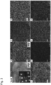
- Figure 3 shows an HAADF (High Angle Annular Dark Field) image of high magnification, element mapping images, and a diffraction pattern.
- HAADF High Angle Annular Dark Field
- Figure 4A shows an HAADF image, element mapping images, and a diffraction pattern of STEM-EDX for a molded material subjected to the solution heat treatment (water cooling). Satellite spots due to the ordered phase are observed in the diffraction pattern. From the element mapping images, Ni- and Ti-enriched fine grains having a diameter of slightly less than 20 nm existed.
- Figure 4B shows an HAADF image, element mapping images, and a diffraction pattern of STEM-EDX for a molded material subjected to the solution heat treatment (air cooling).
- the satellite spot intensity appearing in the diffraction pattern is higher than that of the water-cooled material shown in Figure 4A .
- the diameter of Ni- and Ti-enriched fine grains was more than three times larger than that of a water-cooled material and was about 70 nm.
- Figure 5 is a photograph showing an impeller of a fluid machine, which is an example of a product including the HEA member according to the present invention. Since the HEA product of the present invention is produced by the metal powder additive manufacturing process, even a complicated shaped object as shown in Figure 5 can be easily molded. Since the impeller using the HEA member of the present invention has both high mechanical properties and high corrosion resistance, it can exhibit excellent durability under severe operating environments.
- FIG. 6 is a schematic cross-sectional view showing a centrifugal compressor in which the impeller of the present invention is incorporated, which is another example of the product including the HEA member according to the present invention.
- Use of the impeller of the present invention exhibiting excellent durability even in a severe operating environment can contribute to improvement of long-term reliability of the centrifugal compressor.
- the raw material mixing and melting step was performed: specifically, raw materials were mixed in the nominal composition shown in Table 1 and were melted by a vacuum melting process to form a molten metal.
- the atomizing step was then performed: specifically, alloy powder was formed from the molten metal by the gas atomizing process. The obtained alloy powder was then classified using a sieve and was sorted according to a grain diameter of 45 ⁇ m or less to provide HEA powders P1 to P6.
- Table 1 Nominal compositions of HEA powders P1 to P6 (unit: atomic%) HEA powder Co Cr Fe Ni Ti Mo P1 26.8 17.9 17.9 26.8 8.9 1.8 P2 26.3 17.5 17.5 26.3 8.8 3.5 P3 25.4 17.0 17.0 25.4 8.5 6.8 P4 25.0 16.7 16.7 25.0 8.3 8.3 P5 28.9 19.2 19.2 23.1 7.7 1.9 P6 31.3 20.8 20.8 18.8 6.3 2.1
- the HEA powder P1 prepared in Experiment 1 was subjected to the SLM process according to the procedure of the additive manufacturing step using a powder additive manufacturing apparatus (EOSINT M280 manufactured by EOS GmbH) as shown in Figure 2 to mold an alloy laminated molded body (a prismatic material of 25 mm ⁇ 25 mm ⁇ 70 mm in height; a building direction is in the height direction).
- EOSINT M280 powder additive manufacturing apparatus manufactured by EOS GmbH
- the HEA member M1S was subjected to the pseudo solution heat treatment (maintaining it in the atmosphere at a temperature of 1120°C for 3 hours and then quenching it) to produce an HEA member M1S-S of the pseudo solution molded body.
- the high-temperature HEA member taken out from a furnace was immersed in purified water at room temperature and cooled with water as a quenching process, and this sample was designated as an HEA member M1S-SW.
- the high-temperature HEA member was placed on a ceramic plate for air cooling as a quenching process and, this sample was designated as an HEA member M1S-SA.
- the HEA powders P2 to P6 were subjected to the additive manufacturing step, the taking-out step, and the pseudo solution heat treatment step in the same manner as above to produce HEA members M2S-SW to M6S-SW and M2S-SA to M6S-SA of the pseudo solution molded body.
- the HEA powders P1 to P6 prepared in Experiment 1 were subjected to the additive manufacturing step and the taking-out step in the same manner as above to produce HEA members M1S to M6S of the alloy laminated molded body.
- These alloy laminated molded bodies are samples which are not subjected to the pseudo solution heat treatment step and serve as reference samples for confirming the influence of the pseudo solution heat treatment.
- the HEA powders P1 to P4 prepared in Experiment 1 were subjected to the arc melting process using water-cooled copper mold to forge an ingot (prismatic material having a width of 14 mm, a length of 80 mm, and a height of 20 mm) to produce ordinary forged HEA members M1F to M4F.
- melting was repeated 5 times or more.
- the hot forging step by press working was repeated twice in the conditions of the compression ratio of 30% and the compression rate of 30 mm/s.
- the cooling after hot forging was air cooling.
- the HEA members M1S-SW prepared in Experiment 2 were further subjected to the aging treatment (maintaining it in the atmosphere at temperatures of 600°C, 700°C, and 800°C for 1 hour and then air cooling it) to obtain HEA members M1S-SW-A600, M1S-SW-A700, and M1S-SW-A800 of the pseudo solution molded body.
- HEA members M1S-SW-A500 and M1S-SW-A900 of the pseudo solution molded body were produced by the aging treatment that maintains them in the atmosphere at temperatures of 500°C and 900°C for 1 hour.
- a specimen for microstructure observation was sampled from each of the HEA members produced above and microscopic observation was performed using an optical microscope, various electron microscopes (SEM, TEM, and STEM-EDX), and X-ray diffractometer (XRD). Table 2 shows the microstructure observation results together with the production specification of each HEA member.
- Table 2 Production specification and microstructure observation results of each HEA member HEA member HEA Pseudo solution heat treatment powder (quenching process)
- Parent phase structure Precipitate Crystal shape (crystal structure) Average grain diameter
- Main precipitate phase (shape) Precipitation form Average grain diameter of precipitate M1F P1 no Equiaxed crystal (SC+FCC) About 150 ⁇ m Ni 3 Ti (needle crystal) Collected in disorder - M1S Columnar crystal (SC+FCC) About 40 ⁇ m - - - M1S-SW (water cooling) Equiaxed crystal (SC+FCC) About 60 ⁇ m Ni-Ti-Co alloy (ultrafine grain) Dispersed 20nm M1S-SA yes (air cooling) About 80 ⁇ m 70nm M1S-SW-A500 *yes (water cooling) About 60 ⁇ m 20nm M1S-SW-A600 About 60 ⁇ m 30nm M1S-SW-A700 About 60 ⁇ m 60nm M1S-SW-A800
- the ordinary forged HEA members M1F to M4F had a structure consisting of equiaxed crystals having an average grain diameter of about 150 ⁇ m.
- the crystal structure of the equiaxed crystal was a mixture of simple cubic (SC) and face-centered cubic (FCC) (in other words, it clearly contained FCC).
- the parent phase structure of the HEA members M1S to M4S of the alloy laminated molded body had a structure in which fine columnar crystals (average grain diameter of 40 ⁇ m or less) (so-called local quenching solidified structure) were forested along the building direction of the laminated molded body.
- the crystal structure of the columnar crystal was a mixture of simple cubic (SC) and face-centered cubic (FCC) (in other words, it clearly contained FCC).
- SC simple cubic
- FCC face-centered cubic
- the columnar crystal referred to here is defined as a crystal having a ratio of the major axis length to the minor axis length of the crystal grain of 2 or more.
- the parent phase structure of the HEA member of the pseudo solution molded body had an equiaxed crystal shape, but the average crystal grain diameter was slightly different depending on the quenching process of the pseudo solution heat treatment and the presence or absence of the aging treatment. Specifically, in the samples water-cooled as the quenching process (M1S-SW to M6S-SW), the average grain diameter of the parent phase crystals was about 60 ⁇ m. In the samples air-cooled as the quenching process (M1S-SA to M6S-SA), the average grain diameter of the parent phase crystals was about 80 ⁇ m.
- the samples subjected to the aging treatment after the pseudo solution heat treatment had an average grain diameter of the parent phase crystals of about 60 ⁇ m, which was the same as that of M1S-SW.
- the sample subjected to the aging treatment after the pseudo solution heat treatment had an average grain diameter of the parent phase crystals of about 80 ⁇ m.
- the sample subjected to the aging treatment after the pseudo solution heat treatment had an average grain diameter of the parent phase crystals of about 100 ⁇ m.
- the crystal structure of these equiaxed crystals was a mixture of simple cubic (SC) and face-centered cubic (FCC) (in other words, they clearly contained FCC). It was confirmed by TEM and STEM-EDX that fine grains having an average grain diameter of 100 nm or less existed in these parent phase crystals and Ni component and Ti component were more enriched in these fine grains than in the parent phase crystals.
- a specimen (parallel part diameter: 4 mm and parallel part length: 20 mm) for tensile test was sampled from each of the HEA members produced above.
- the specimens of HEA members of the alloy laminated molded body and the pseudo solution alloy molded body were sampled so that the longitudinal direction of the specimen agreed with the building direction.
- a polarization specimen (15 mm long ⁇ 15 mm wide ⁇ 2 mm thick) for pitting corrosion test was sampled from each of the HEA members produced above.
- the pitting corrosion test was carried out according to JIS G 0577 for each polarization specimen.
- the anode polarization curve of the polarization specimen was obtained in the conditions of "test area: 1 cm 2 , electrode for preventing crevice corrosion mounted on a polarization specimen, reference electrode: saturated silver-silver chloride electrode, test solution: 3.5% sodium chloride aqueous solution deaerated with argon gas, test temperature: 80°C, and potential sweep rate: 20 mV/min" to determine the electric potential corresponding to a current density of 100 ⁇ A/cm 2 when the pitting corrosion occurred.
- 0.50 V or more was judged to be "passed", and less than 0.50 V was judged to be "failed”.
- the results of the pitting corrosion test are also shown in Table 3.
- Table 3 Measurement results of mechanical properties and corrosion resistance of each HEA member HEA member Mechanical property Corrosion resistance Tensile strength (MPa) Passed or failed Breaking elongation (%) Passed or failed Electric potential when pitting corrosion occurrs (V vs.
- the ordinary forged HEA members M1F to M4F which are samples not subjected to the additive manufacturing step, had a tensile strength of less than 1100 MPa and a breaking elongation of less than 10%, and failed in mechanical properties. It has been demonstrated that the HEA members M1S to M3S and M5S to M6S of the alloy laminated molded body, which are samples subjected to the additive manufacturing step but not subjected to the pseudo solution heat treatment step had a tensile strength of 1100 MPa or more and a breaking elongation of 10% or more, and exhibited good mechanical properties.
- the characteristics of the HEA member M1S-SW-A500 for which the aging treatment temperature was 500°C after the pseudo solution heat treatment were equivalent to those of H1S-SW without the aging treatment, and the HEA member M1S-SW-A900 (the average grain diameter of ultrafine grains exceeding 100 nm) for which the aging treatment temperature was 900°C remarkably decreased mechanical properties.
- the average grain diameter of ultrafine grains dispersed and precipitated in the parent phase crystals was preferably 100 nm or less.
- the HEA members M1S-SW to M3S-SW, M1S-SA to M3S-SA, M5S-SW to M6S-SW, and M5S-SA to M6S-SA of the pseudo solution alloy molded body had a tensile strength of 1100 MPa or more, a breaking elongation of 10% or more, and good mechanical properties.
- the HEA members M6S-SW and M6S-SA produced using the HEA powder P6 having a relatively low content of the Ni component and the Ti component had a breaking elongation of 25% or more and particularly excellent ductility.
- the HEA members M1S-SW, M1S-SA to M3S-SW, M3S-SA and M5S-SW, and M5S-SA produced using the HEA powders P1 to P3 and P5 having higher contents of the Ni component and Ti component than the HEA powder P6 had a tensile strength of 1200 MPa or more and mechanical strength was particularly excellent.
- the HEA member of the present invention is considered to have excellent corrosion resistance by the combination of the elements themselves (Co-Cr-Fe-Ni-Ti-Mo). Since the HEA member of the pseudo solution alloy molded body according to the embodiment of the present invention provided a higher electric potential when pitting corrosion occurs than the other HEA members, the HEA member according to the embodiment of the present invention is expected to have higher corrosion resistance.
- An impeller shown in Figure 5 was produced by the same procedure as the process for producing the HEA member M1E-SW of the pseudo solution alloy molded body.
- the obtained impeller was subjected to internal defect inspection by X-ray CT scan and dimension measurement. As a result, no internal defects which adversely affected the mechanical properties were observed and no deformation with respect to the designed dimensions was observed. This experiment confirmed the effectiveness of the present invention.
Landscapes
- Engineering & Computer Science (AREA)
- Chemical & Material Sciences (AREA)
- Materials Engineering (AREA)
- Mechanical Engineering (AREA)
- Manufacturing & Machinery (AREA)
- Organic Chemistry (AREA)
- Metallurgy (AREA)
- Physics & Mathematics (AREA)
- Thermal Sciences (AREA)
- General Engineering & Computer Science (AREA)
- Optics & Photonics (AREA)
- Crystallography & Structural Chemistry (AREA)
- Plasma & Fusion (AREA)
- Powder Metallurgy (AREA)
- Manufacture Of Metal Powder And Suspensions Thereof (AREA)
- Heat Treatment Of Steel (AREA)
Abstract
Description
- The present invention relates to an alloy member produced by a powder additive manufacturing process using a high entropy alloy, a process for producing the alloy member, and a product including the alloy member.
- Recently, as an alloy of a new technical idea which has distinguished itself from the conventional technical idea of alloy (for example, an alloy obtained by adding a small amount of a plurality of subcomponent elements to one to three main component elements), high entropy alloy (High Entropy Alloy: HEA) has been proposed. HEA is defined as an alloy composed of five or more main metal elements (5 to 35 atomic% each), and it is known that the following characteristics are exerted.
- Examples of the characteristics include (a) stabilization of the mixing condition due to the negative increase in the mixing entropy term in Gibbs' free energy formula; (b) diffusion delay due to complicated microstructure; (c) high hardness and reduction in temperature dependence of mechanical properties caused by high lattice distortion due to difference in size of constituent atoms; and (d) improvement of corrosion resistance by combined effect (also called cocktail effect) due to coexistence of various elements.
- For example, Patent Literature 1 (JP Patent Publication (Kokai) No. 2002-173732) discloses a high-entropy multicomponent alloy obtained by casting or synthesizing a plurality of metal elements, wherein the alloy contains 5 to 11 main metal elements and the number of moles of each main metal element is set to 5% to 30% of the total number of moles of the alloy. It is also discloses that the main metal elements are selected from the metal element group consisting of aluminum, titanium, vanadium, chromium, iron, cobalt, nickel, copper, zirconium, molybdenum, palladium, and silver.
- Patent Literature 1 purports that there can be provided a high-entropy multicomponent alloy having a higher hardness, higher heat resistance, and higher corrosion resistance than conventional carbon steel or alloy carbon steel in the cast condition.
- Patent Literature 1:
JP Patent Publication (Kokai) No. 2002-173732 - However, as a result of various investigations by the present inventors on HEA, HEA tended to occur elemental segregation and tissue spots at forging due to complex alloy composition and was difficult to obtain a homogeneous ingot. There are problems to be solved such that elemental segregation and tissue spots in the alloy member lead to variation in characteristics depending on the site, particularly, degradation of mechanical strength such as ductility, or decrease in corrosion resistance.
- Since HEA has high hardness and temper softening resistance, the problem is that HEA is difficult to process by machining to produce a desired shape member. This is a major obstacle to putting the HEA member into practical use and commercializing it, which is a problem to be solved.
- As described above, since HEA has attractive characteristics which cannot be obtained by conventional alloys, the HEA member excellent in homogeneity of alloy composition and microstructure and excellent in shape controllability, and its production process have been strongly demanded to be developed.
- To meet the above demands, the object of the present invention is to provide an alloy member that is excellent in homogeneity of both the alloy composition and microstructure and excellent in shape controllability and includes a high entropy alloy (HEA) having high mechanical properties and high corrosion resistance, a process for producing the same, and a product including the alloy member.
-
- (I) One aspect of the present invention provides an alloy member including a high entropy alloy, wherein the alloy member has a chemical composition comprising elements of Co (cobalt), Cr (chromium), Fe (iron), Ni (nickel), and Ti (titanium) each in an amount within a range of 5 atomic% or more and 35 atomic% or less and Mo (molybdenum) in an amount within a range of more than 0 atomic% and 8 atomic% or less, the remainder consisting of unavoidable impurities; and ultrafine grains having an average grain diameter of 100 nm or less are dispersed and precipitated in a parent phase crystal grain.
- (II) Another aspect of the present invention provides a process for producing the above alloy member, the process comprising:
- a raw material mixing and melting step of mixing and melting raw materials of the alloy to form a molten metal;
- an atomizing step of forming an alloy powder from the molten metal; and
- an additive manufacturing step of forming an alloy laminated molded body having a desired shape by a metal powder additive manufacturing process using the alloy powder.
- (III) Still another aspect of the present invention provides a process for producing the above alloy member, the process comprising:
- a raw material mixing and melting step of mixing and melting raw materials of the alloy to form a molten metal;
- an atomizing step of forming an alloy powder from the molten metal;
- an additive manufacturing step of forming an alloy laminated molded body having a desired shape by a metal powder additive manufacturing process using the alloy powder; and
- a pseudo solution heat treatment step of performing pseudo solution heat treatment on the alloy laminated molded body in a temperature range of 1080°C or more and 1180°C or less.
- (IV) Still another embodiment of the present invention provides a product comprising the above alloy member,
wherein the product is an impeller of a fluid machine. - The present application claims a priority to
Japanese Patent Application No. 2017-154657 - The present invention can provide an alloy member that is excellent in homogeneity of both the alloy composition and microstructure and excellent in shape controllability and includes a high entropy alloy having high mechanical properties and high corrosion resistance, a process for producing the same, and a product including the alloy member.
-
- [
Figure 1] Figure 1 is a process chart showing an example of a process for producing an alloy member according to the present invention. - [
Figure 2] Figure 2 is a schematic cross-sectional view showing an example of a configuration of a powder additive manufacturing apparatus for a laser beam melting process and an example of an additive manufacturing process. - [
Figure 3] Figure 3 is a high angle scattering annular dark field scanning transmission electron microscopic image (HAADF-STEM image) showing an example of a microstructure of a pseudo solution alloy molded body according to the present invention. - [
Figure 4A] Figure 4A is a high angle scattering annular dark field scanning transmission electron microscopic image (HAADF-STEM image) showing an example of a microstructure of a pseudo solution alloy molded body according to the present invention. - [
Figure 4B] Figure 4B is a high angle scattering annular dark field scanning transmission electron microscopic image (HAADF-STEM image) showing an example of a microstructure of a pseudo solution alloy molded body according to the present invention. - [
Figure 5] Figure 5 is a photograph showing an impeller of a fluid machine, which is an example of a product including the alloy member according to the present invention. - [
Figure 6] Figure 6 is a schematic cross-sectional view showing a centrifugal compressor in which the impeller of the present invention is incorporated, which is another example of the product including the alloy member according to the present invention and showing. - In the present invention, the following improvements and modifications can be made on the above-described alloy member (I).
- (i) The parent phase crystal grains have an average crystal grain diameter of 100 µm or less.
- (ii) The ultrafine grains are crystalline grains in which the Ni component and the Ti component are more enriched than in the parent phase crystals.
- (iii) The chemical composition comprises 20 atomic% or more and 35 atomic% or less of Co; 10 atomic% or more and 25 atomic% or less of Cr; 10 atomic% or more and 25 atomic% or less of Fe; 15 atomic% or more and 30 atomic% or less of Ni; and 5 atomic% or more and 15 atomic% or less of Ti.
- (iv) The chemical composition comprises 25 atomic% or more and 33 atomic% or less of Co; 15 atomic% or more and 23 atomic% or less of Cr; 15 atomic% or more and 23 atomic% or less of Fe; 17 atomic% or more and 28 atomic% or less of Ni; 5 atomic% or more and 10 atomic% or less of Ti; and 1 atomic% or more and 7 atomic% or less of Mo.
- (v) The chemical composition comprises 25 atomic% or more and less than 30 atomic% of Co; 15 atomic% or more and less than 20 atomic% of Cr; 15 atomic% or more and less than 20 atomic% of Fe; 23 atomic% or more and 28 atomic% or less of Ni; 7 atomic% or more and 10 atomic% or less of Ti; and 1 atomic% or more and 7 atomic% or less of Mo.
- (vi) The chemical composition comprises 30 atomic% or more and 33 atomic% or less of Co; 20 atomic% or more and 23 atomic% or less of Cr; 20 atomic% or more and 23 atomic% or less of Fe; 17 atomic% or more and less than 23 atomic% of Ni; 5 atomic% or more and less than 7 atomic%s of Ti; and 1 atomic% or more and 3 atomic% or less of Mo.
- (vii) The alloy member has a tensile strength of 1100 MPa or more and a breaking elongation of 10% or more. The upper limit of the tensile strength is not particularly limited, but it can be 1500 MPa, for example. The upper limit of the breaking elongation is not particularly limited either, but it can be set to 40%, for example.
- (viii) The parent phase crystals have a columnar crystal shape and the crystal structure thereof comprises at least one of simple cubic system and face-centered cubic system.
- (ix) The parent phase crystals have an equiaxed crystal shape and the crystal structure thereof comprises at least one of simple cubic system and face-centered cubic system.
- In the present invention, the following improvements and modifications can be made on the above-described process (III) for producing the alloy member.
(x) The pseudo solution heat treatment step is a step of holding the alloy laminated molded body in the temperature range and then cooling the resultant with water or air. - In the present invention, the following improvements and modifications can be made on to the above-described processes (II) and (III) for producing the alloy member.
(xi) The heat source used for the metal powder additive manufacturing process in the additive manufacturing step is laser light. - In the present invention, the following improvements and modifications can be made on the product (IV) including the above-described alloy member.
(xii) The product is a centrifugal compressor in which the impeller is incorporated. - As described above, the high entropy alloy (HEA) has attractive characteristics which cannot be obtained by conventional alloys (for example, high hardness and temper softening resistance), but a problem thereof is that HEA was difficult to process to produce a desired shape member.
- The inventors of the present invention have performed intensive studies on the alloy composition and the shape control process in order to develop an HEA member excellent in shape controllability and ductility without sacrificing the characteristics of HEA. As a result, it has been found that formation of the alloy laminated molded body by the electron beam additive manufacturing process using powder of a Co-Cr-Fe-Ni-Ti-Mo based alloy can provide a HEA member which is more excellent in shape controllability and ductility than the conventional ordinary forged HEA member.
- Specifically, the HEA member has been found to be capable of obtaining in a near net shape and have good mechanical properties (for example, breaking elongation of 3% or more and tensile strength of 1000 MPa or more). However, in view of practical durability and long-term reliability in the HEA member and the mechanical apparatus using it, it is desirable that the HEA member have better ductility (for example, breaking elongation of 10% or more).
- In order to realize a HEA member having desirable characteristics, the present inventors have performed further detailed investigations and studies on the relationship among the producing process, microstructure, and mechanical properties. As a result, it has been found that formation of an alloy laminated molded body by the laser additive manufacturing process can provide the HEA member which is more excellent in shape controllability and ductility than the HEA member molded by the electron beam additive manufacturing process.
- It has been further found that application of a predetermined heat treatment to a molded body after the laser additive manufacturing can provide microstructure in which nanoscale ultrafine grains are dispersed and precipitated in parent phase crystal grains and can significantly improve mechanical strength and ductility. The present invention has been completed based on these findings.
- Hereinafter, embodiments of the present invention will be described in accordance with the producing procedure of the HEA member with reference to the drawings. The present invention is not limited to the embodiments taken here, and combinations and improvements may be made as appropriate within a scope not deviating from the technical idea of the invention.
-
Figure 1 is a process chart showing an example of a process for producing an alloy member according to the present invention. As shown inFigure 1 , the producing process of the present invention has a raw material mixing and melting step, an atomizing step, an additive manufacturing step, a taking-out step, and a pseudo solution heat treatment step. Hereinafter, embodiments of the present invention will be described more specifically. - As shown in
Figure 1 , firstly, the raw material mixing and melting step is carried out wherein the raw materials are mixed to obtain a desired HEA composition (Co-Cr-Fe-Ni-Ti-Mo) and melted to form amolten metal 10. There are no particular limitations on the process of mixing and melting the raw materials, and conventional processes for producing the alloy having high strength and high corrosion resistance can be used. For example, vacuum melting can be suitably used as a melting process. It is also preferable to refine themolten metal 10 by using the vacuum carbon deoxidation process or the like in combination. - The HEA composition of the present invention includes five elements of Co, Cr, Fe, Ni, and Ti, as main components, each in an amount within the range of 5 atomic% or more and 35 atomic% or less, and includes Mo in an amount within a range of more than 0 atomic% to 8 atomic% or less as a subcomponent, the reminder consisting of unavoidable impurities.
- More specifically, the Co component is preferably 20 atomic% or more and 35 atomic% or less, more preferably 25 atomic% or more and 33 atomic% or less. The Cr component is preferably 10 atomic% or more and 25 atomic% or less, more preferably 15 atomic% or more and 23 atomic% or less. The Fe component is preferably 10 atomic% or more and 25 atomic% or less, more preferably 15 atomic% or more and 23 atomic% or less. The Ni component is preferably 15 atomic% or more and 30 atomic% or less, more preferably 17 atomic% or more and 28 atomic% or less. The Ti component is preferably 5 atomic% or more and 15 atomic% or less, more preferably 5 atomic% or more and 10 atomic% or less. The Mo component is preferably more than 0 atomic% and 8 atomic% or less, more preferably 1 atomic% or more and 7 atomic% or less. Controlling to these composition ranges can achieve both improvement in ductility and improvement in mechanical strength. In other words, when each component deviates from their respective preferred composition ranges, it will be difficult to achieve desirable properties.
- Within the above composition range described in the last paragraph, the Co component is more preferably 25 atomic% or more and less than 30 atomic%, the Cr component is more preferably 15 atomic% or more and less than 20 atomic%, the Fe component is more preferably 15 atomic% or more and less than 20 atomic%, the Ni component is more preferably 23 atoms% or more and 28 atomic% or less, the Ti component is more preferably 7 atomic% or more and 10 atomic% or less, and the Mo component is more preferably 1 atomic% or more and 7 atomic% or less, when the improvement of the mechanical strength precedes others.
- Within the above composition range described in the second last paragraph, the Co component is more preferably 30 atomic% or more and 33 atomic% or less, the Cr component is more preferably 20 atomic% or more and 23 atomic% or less, the Fe component is more preferably 20 atomic% or more and 23 atomic% or less, the Ni component is more preferably 17 atoms% or more and less than 23 atomic%, the Ti component is more preferably 5 atomic% or more and less than 7 atomic%, and the Mo component is more preferably 1 atomic% or more and 3 atomic% or less, when the improvement of the ductility precedes others.
- The atomization step of forming an
alloy powder 20 from themolten metal 10 is performed. There is no particular limitation on the atomizing process, and the conventional processes can be used. For example, a gas atomizing process or a centrifugal atomizing process can be preferably used. - The average grain diameter of the
alloy powder 20 is preferably 10 µm or more and 200 µm or less, more preferably 10 µm or more and 50 µm or less, in view of handling property and filling property. When the average grain diameter is less than 10 µm, thealloy powder 20 easily flies up in the next additive manufacturing step, which is a factor of reducing shape accuracy of the alloy laminated molded body. On the other hand, when the average grain diameter exceeds 200 µm, the surface roughness of the alloy laminated molded body increases or the melting of thealloy powder 20 becomes insufficient in the next additive manufacturing step. - The additive manufacturing step of forming an alloy laminated molded
body 101 having a desired shape is performed by the metal powder additive manufacturing process using the above-producedalloy powder 20. Application of the metal powder additive manufacturing process for molding a metal member of a near net shape along with melting and solidifying rather than sintering can produce a three-dimensional member having a hardness equal to or higher than that of a forged material and having a complicated shape. As an additive manufacturing process, a metal powder additive manufacturing process using a selective laser melting (SLM) process can be suitably used. - The additive manufacturing step by the SLM process will be described.
Figure 2 is a schematic view showing a configuration of a powderadditive manufacturing apparatus 100 according to the SLM process. Astage 102 is lowered by the thickness of one layer (for example, about 20 to 50 µm) of the alloy laminated moldedbody 101 to be molded. Analloy powder 105 is supplied from apowder supply container 104 onto abase plate 103 on the upper surface of thestage 102, and thealloy powder 105 is flattened by arecoater 160 to form a powder bed 107 (laminated powder). - Based on a 2D slice data converted from a 3D-CAD data of the alloy laminated molded
body 101 to be molded, the unmelted powder on thebase plate 103 is irradiated with alaser 109 output from alaser oscillator 108 through agalvanometer mirror 110 to form a micro-molten pool, which is then moved and sequentially solidified, whereby a solidifiedlayer 112 in the form of a 2D slice is formed. The unmelted powder is recovered in a recovery container 111. Lamination is performed by repeating this operation to produce the alloy laminated moldedbody 101. - A specimen for microstructure observation was sampled from the alloy laminated molded
body 101 after the taking-out step and the microstructure of the sample was observed using an electron microscope. As a result, the parent phase of the alloy laminated moldedbody 101 had a structure (so-called quenched solidified structure) in which fine columnar crystals (average width of 50 µm or less) were forested along the building direction of the alloy laminated moldedbody 101. - Heat treatment for rapidly cooling the alloy laminated molded
body 101 as described above can be performed as appropriate after heating and holding at a stable temperature. The temperature of the present heat treatment is preferably in the range of 1080 to 1180°C, more preferably 1100 to 1140°C. When it is below 1080°C, needle crystals of an intermetallic compound phase precipitate, and when it exceeds 1180°C, the crystal grain diameter becomes coarse. In the present application, the heat treatment as described above is called pseudo solution heat treatment because of the following reasons: the solid solubility limit of the alloy is not clear, and ultrafine grains having an average grain diameter of 100 nm or less are dispersed and precipitated in the alloy member which is the final product. - It is preferable to maintain the alloy laminated molded
body 101 within the temperature range for a suitable period and then quench (for example, air cooling or water cooling) the resultant. Particularly, allowing the alloy laminated moldedbody 101 to undergo a quick change of the temperature through a temperature range in which the intermetallic compound phase easily grows grain(for example, a temperature range of 900 to 800°C) (for example, to cool at a rate of 10°C/s or more) provides a pseudo solution alloy molded body having the microstructure that nanoscale ultrafine grains are dispersed and precipitated. Performing the aging treatment step of maintaining the pseudo solution alloy molded body at a temperature lower than a temperature range in which the intermetallic compound phase easily grows grain(for example, a temperature range of 900 to 800°C), for example, more than 500°C to less than 900°C, the number of nanoscale ultrafine grains in the pseudo solution alloy molded body can be increased to further improve the strength. - The average grain diameter of the ultrafine grains dispersed and precipitated is preferably 100 nm or less, more preferably 20 nm or more and 80 nm or less. When the average grain diameter of ultrafine grains is 20 nm or more and 80 nm or less, the ductility and corrosion resistance are excellent, and the mechanical strength can be increased. When the average grain diameter of ultrafine grains exceeds 100 nm, the mechanical properties abruptly decrease.
-
Figure 3 shows an HAADF (High Angle Annular Dark Field) image of high magnification, element mapping images, and a diffraction pattern. In the diffraction pattern, a satellite pattern due to a fine ordered phase observed in the molded material subjected to the pseudo solution heat treatment was observed, but its presence could not be confirmed from the element mapping images. It is inferred from this finding that the solidification rate in the molded material is remarkably high and that the ordered phase is so ultrafine as to exceed the detection limit of STEM-EDX. - In order to investigate the microstructure of the pseudo solution alloy molded body in more detail, microstructure observation was carried out using STEM-EDX.
-
Figure 4A shows an HAADF image, element mapping images, and a diffraction pattern of STEM-EDX for a molded material subjected to the solution heat treatment (water cooling). Satellite spots due to the ordered phase are observed in the diffraction pattern. From the element mapping images, Ni- and Ti-enriched fine grains having a diameter of slightly less than 20 nm existed. -
Figure 4B shows an HAADF image, element mapping images, and a diffraction pattern of STEM-EDX for a molded material subjected to the solution heat treatment (air cooling). The satellite spot intensity appearing in the diffraction pattern is higher than that of the water-cooled material shown inFigure 4A . The diameter of Ni- and Ti-enriched fine grains was more than three times larger than that of a water-cooled material and was about 70 nm. -
Figure 5 is a photograph showing an impeller of a fluid machine, which is an example of a product including the HEA member according to the present invention. Since the HEA product of the present invention is produced by the metal powder additive manufacturing process, even a complicated shaped object as shown inFigure 5 can be easily molded. Since the impeller using the HEA member of the present invention has both high mechanical properties and high corrosion resistance, it can exhibit excellent durability under severe operating environments. -
Figure 6 is a schematic cross-sectional view showing a centrifugal compressor in which the impeller of the present invention is incorporated, which is another example of the product including the HEA member according to the present invention. Use of the impeller of the present invention exhibiting excellent durability even in a severe operating environment can contribute to improvement of long-term reliability of the centrifugal compressor. - Hereinafter, the present invention will be described in more detail by way of Examples and Comparative Examples. The present invention is not limited to these examples.
- The raw material mixing and melting step was performed: specifically, raw materials were mixed in the nominal composition shown in Table 1 and were melted by a vacuum melting process to form a molten metal. The atomizing step was then performed: specifically, alloy powder was formed from the molten metal by the gas atomizing process. The obtained alloy powder was then classified using a sieve and was sorted according to a grain diameter of 45 µm or less to provide HEA powders P1 to P6.
-
Table 1: Nominal compositions of HEA powders P1 to P6 (unit: atomic%) HEA powder Co Cr Fe Ni Ti Mo P1 26.8 17.9 17.9 26.8 8.9 1.8 P2 26.3 17.5 17.5 26.3 8.8 3.5 P3 25.4 17.0 17.0 25.4 8.5 6.8 P4 25.0 16.7 16.7 25.0 8.3 8.3 P5 28.9 19.2 19.2 23.1 7.7 1.9 P6 31.3 20.8 20.8 18.8 6.3 2.1 - The HEA powder P1 prepared in Experiment 1 was subjected to the SLM process according to the procedure of the additive manufacturing step using a powder additive manufacturing apparatus (EOSINT M280 manufactured by EOS GmbH) as shown in
Figure 2 to mold an alloy laminated molded body (a prismatic material of 25 mm × 25 mm × 70 mm in height; a building direction is in the height direction). - After the additive manufacturing step, an HEA member M1S of the alloy laminated molded body was taken out.
- After the taking-out step, the HEA member M1S was subjected to the pseudo solution heat treatment (maintaining it in the atmosphere at a temperature of 1120°C for 3 hours and then quenching it) to produce an HEA member M1S-S of the pseudo solution molded body. The high-temperature HEA member taken out from a furnace was immersed in purified water at room temperature and cooled with water as a quenching process, and this sample was designated as an HEA member M1S-SW. Separately, the high-temperature HEA member was placed on a ceramic plate for air cooling as a quenching process and, this sample was designated as an HEA member M1S-SA.
- (Preparation of HEA members M2S-SW, M2S-SA to M6S-SW, and M6S-SA of pseudo solution molded body)
- The HEA powders P2 to P6 were subjected to the additive manufacturing step, the taking-out step, and the pseudo solution heat treatment step in the same manner as above to produce HEA members M2S-SW to M6S-SW and M2S-SA to M6S-SA of the pseudo solution molded body.
- The HEA powders P1 to P6 prepared in Experiment 1 were subjected to the additive manufacturing step and the taking-out step in the same manner as above to produce HEA members M1S to M6S of the alloy laminated molded body. These alloy laminated molded bodies are samples which are not subjected to the pseudo solution heat treatment step and serve as reference samples for confirming the influence of the pseudo solution heat treatment.
- The HEA powders P1 to P4 prepared in Experiment 1 were subjected to the arc melting process using water-cooled copper mold to forge an ingot (prismatic material having a width of 14 mm, a length of 80 mm, and a height of 20 mm) to produce ordinary forged HEA members M1F to M4F. In order to minimize element segregation and tissue spot during forging, melting was repeated 5 times or more. Then, after heating and holding at 950°C for 15 minutes in the atmosphere, the hot forging step by press working was repeated twice in the conditions of the compression ratio of 30% and the compression rate of 30 mm/s. The cooling after hot forging was air cooling. These ordinary forged members are samples which are not subjected to the additive manufacturing step and serve as reference samples for confirming the influence of the metal powder additive manufacturing.
- In order to control the ultrafine grains dispersed and precipitated in the parent phase crystals, the HEA members M1S-SW prepared in Experiment 2 were further subjected to the aging treatment (maintaining it in the atmosphere at temperatures of 600°C, 700°C, and 800°C for 1 hour and then air cooling it) to obtain HEA members M1S-SW-A600, M1S-SW-A700, and M1S-SW-A800 of the pseudo solution molded body. As Comparative Example, HEA members M1S-SW-A500 and M1S-SW-A900 of the pseudo solution molded body were produced by the aging treatment that maintains them in the atmosphere at temperatures of 500°C and 900°C for 1 hour.
- A specimen for microstructure observation was sampled from each of the HEA members produced above and microscopic observation was performed using an optical microscope, various electron microscopes (SEM, TEM, and STEM-EDX), and X-ray diffractometer (XRD). Table 2 shows the microstructure observation results together with the production specification of each HEA member.
-
Table 2: Production specification and microstructure observation results of each HEA member HEA member HEA Pseudo solution heat treatment powder (quenching process) Parent phase structure Precipitate Crystal shape (crystal structure) Average grain diameter Main precipitate phase (shape) Precipitation form Average grain diameter of precipitate M1F P1 no Equiaxed crystal (SC+FCC) About 150µm Ni3Ti (needle crystal) Collected in disorder - M1S Columnar crystal (SC+FCC) About 40µm - - - M1S-SW (water cooling) Equiaxed crystal (SC+FCC) About 60µm Ni-Ti-Co alloy (ultrafine grain) Dispersed 20nm M1S-SA yes (air cooling) About 80µm 70nm M1S-SW-A500 *yes (water cooling) About 60µm 20nm M1S-SW-A600 About 60µm 30nm M1S-SW-A700 About 60µm 60nm M1S-SW-A800 About 80µm 80nm M1S-SW-A900 About 100µm 105nm M2F P2 no Equiaxed crystal (SC+FCC) About 150µm Ni3Ti (needle crystal) Collected in disorder - M2S Columnar crystal (SC+FCC) About 40µm - - - M2S-SW (water cooling) Equiaxed crystal (SC+FCC) About 60µm Ni-Ti-Co alloy (ultrafine grain) Dispersed 20nm M2S-SA yes (air cooling) About 80µm 70nm M3F P3 no Equiaxed crystal (SC+FCC) About 150µm Ni3Ti (needle crystal) Collected in disorder - M3S Columnar crystal (SC+FCC) About 40µm - - - M3S-SW yes (water cooling) Equiaxed crystal (SC+FCC) About 60µm Ni-Ti-Co alloy (ultrafine grain) Dispersed 20nm M3S-SA yes (air cooling) About 80µm 70nm M4F P4 no Equiaxed crystal (SC+FCC) About 150µm Ni3Ti (needle crystal) Collected in disorder - M4S Columnar crystal (SC+FCC) About 40µm - - - M4S-SW yes (water cooling) Equiaxed crystal (SC+FCC) About 60µm Ni-Ti-Co alloy (ultrafine grain) Dispersed 20nm M4S-SA yes (air cooling) About 80µm 70nm M5S-SW P5 yes (water cooling) Equiaxed crystal (SC+FCC) About 60µm Ni-Ti-Co alloy (ultrafine grain) Dispersed 20nm M5S-SA yes (air cooling) About 80µm 70nm M6S-SW P6 yes (water cooling) Equiaxed crystal (SC+FCC) About 60µm Ni-Ti-Co alloy (ultrafine grain) Dispersed 20nm M6S-SA yes (air cooling) About 80µm 70nm ∗: With aging treatment after pseudo solution heat treatment - As shown in Table 2, regarding the parent phase structure, the ordinary forged HEA members M1F to M4F had a structure consisting of equiaxed crystals having an average grain diameter of about 150 µm. As a result of the XRD measurement, the crystal structure of the equiaxed crystal was a mixture of simple cubic (SC) and face-centered cubic (FCC) (in other words, it clearly contained FCC).
- The parent phase structure of the HEA members M1S to M4S of the alloy laminated molded body had a structure in which fine columnar crystals (average grain diameter of 40 µm or less) (so-called local quenching solidified structure) were forested along the building direction of the laminated molded body. As a result of the XRD measurement, the crystal structure of the columnar crystal was a mixture of simple cubic (SC) and face-centered cubic (FCC) (in other words, it clearly contained FCC). The columnar crystal referred to here is defined as a crystal having a ratio of the major axis length to the minor axis length of the crystal grain of 2 or more.
- The parent phase structure of the HEA member of the pseudo solution molded body had an equiaxed crystal shape, but the average crystal grain diameter was slightly different depending on the quenching process of the pseudo solution heat treatment and the presence or absence of the aging treatment. Specifically, in the samples water-cooled as the quenching process (M1S-SW to M6S-SW), the average grain diameter of the parent phase crystals was about 60 µm. In the samples air-cooled as the quenching process (M1S-SA to M6S-SA), the average grain diameter of the parent phase crystals was about 80 µm. The samples subjected to the aging treatment after the pseudo solution heat treatment (M1S-SW-A500, A600, and A700) had an average grain diameter of the parent phase crystals of about 60 µm, which was the same as that of M1S-SW. The sample subjected to the aging treatment after the pseudo solution heat treatment (M1S-SW-A800) had an average grain diameter of the parent phase crystals of about 80 µm. The sample subjected to the aging treatment after the pseudo solution heat treatment (M1S-SW-A900) had an average grain diameter of the parent phase crystals of about 100 µm. As a result of the XRD measurement, the crystal structure of these equiaxed crystals was a mixture of simple cubic (SC) and face-centered cubic (FCC) (in other words, they clearly contained FCC). It was confirmed by TEM and STEM-EDX that fine grains having an average grain diameter of 100 nm or less existed in these parent phase crystals and Ni component and Ti component were more enriched in these fine grains than in the parent phase crystals.
- A specimen (parallel part diameter: 4 mm and parallel part length: 20 mm) for tensile test was sampled from each of the HEA members produced above. The specimens of HEA members of the alloy laminated molded body and the pseudo solution alloy molded body were sampled so that the longitudinal direction of the specimen agreed with the building direction.
- For each specimen, a room temperature tensile test was carried out using a material universal testing machine (according to JIS Z 2241, strain rate: 5 × 10⁻⁵s-1), and tensile strength and breaking elongation were measured. The measurement result of the tensile test was obtained as the average value of three found values excluding the maximum found value and the minimum found value among quintuplicate measurements. In the evaluation of the tensile strength, 1100 MPa or higher was judged as "passed", and less than 1100 MPa was judged as "failed". In the evaluation of the breaking elongation, 10% or more was judged as "passed", and less than 10% was judged as "failed". The results are shown in Table 3 below.
- A polarization specimen (15 mm long × 15 mm wide × 2 mm thick) for pitting corrosion test was sampled from each of the HEA members produced above. The pitting corrosion test was carried out according to JIS G 0577 for each polarization specimen. Specifically, the anode polarization curve of the polarization specimen was obtained in the conditions of "test area: 1 cm2, electrode for preventing crevice corrosion mounted on a polarization specimen, reference electrode: saturated silver-silver chloride electrode, test solution: 3.5% sodium chloride aqueous solution deaerated with argon gas, test temperature: 80°C, and potential sweep rate: 20 mV/min" to determine the electric potential corresponding to a current density of 100 µA/cm2 when the pitting corrosion occurred. In the evaluation of the electric potential when the pitting corrosion occurred, 0.50 V or more was judged to be "passed", and less than 0.50 V was judged to be "failed". The results of the pitting corrosion test are also shown in Table 3.
-
Table 3: Measurement results of mechanical properties and corrosion resistance of each HEA member HEA member Mechanical property Corrosion resistance Tensile strength (MPa) Passed or failed Breaking elongation (%) Passed or failed Electric potential when pitting corrosion occurrs (V vs. Ag/AgCl) Passed or failed M1F 950 Failed 4.5 0.55 Passed M1S 1210 Passed 26 Passed 0.88 Passed M1S-SW 1320 Passed 27 Passed 1.0 Passed M1S-SA 1450 Passed 14 Passed 0.80 Passed M1S-SW-A500 1320 Passed 25 Passed 1.0 ; Passed M1S-SW-A600 1510 Passed 15 Passed 0.91 Passed M1S-SW-A700 1590 : Passed 13 Passed 0.90 Passed M1S-SW-A800 1480 : Passed 11 : Passed 0.72 : Passed M1S-SW-A900 450 Failed 1.1 Failed 0.53 Passed M2F 900 : Failed 2.5 : Failed 0.53 Passed M2S 1131 Passed 23 Passed 0.82 Passed M2S-SW 1220 Passed 20 ; Passed 1.0 Passed M2S-SA 1320 Passed 12 Passed 0.95 Passed M3F 825 Failed 1.2 Failed 0.54 Passed M3S 1210 Passed 20 Passed 0.89 Passed M3S-SW 1210 : Passed 18 : Passed 0.91 : Passed M3S-SA 1302 Passed 11 Passed 0.81 : Passed M4F 710 Failed 0.8 Failed 0.54 Passed M4S 1030 : Failed 8.2 : Failed 0.58 Passed M4S-SW 1080 Failed 6.3 Failed 0.87 Passed M4S-SA 1025 : Failed 3.2 Failed 0.89 : Passed M5S 1150 Passed 32 Passed 0.90 Passed M5S-SW 1305 Passed 28 Passed 1.0 : Passed M5S-SA 1380 Passed 20 Passed 0.98 Passed M6S 1110 Passed 38 Passed 0.89 Passed M6S-SW 1150 Passed 30 Passed 1.0 Passed M6S-SA 1250 : Passed 25 : Passed 0.97 : Passed - As shown in Table 3, the ordinary forged HEA members M1F to M4F, which are samples not subjected to the additive manufacturing step, had a tensile strength of less than 1100 MPa and a breaking elongation of less than 10%, and failed in mechanical properties. It has been demonstrated that the HEA members M1S to M3S and M5S to M6S of the alloy laminated molded body, which are samples subjected to the additive manufacturing step but not subjected to the pseudo solution heat treatment step had a tensile strength of 1100 MPa or more and a breaking elongation of 10% or more, and exhibited good mechanical properties.
- The HEA member produced using the HEA powder P4 whose alloy composition (amount of Mo) was out of the definition of the present invention failed in mechanical properties regardless of the producing process. This result confirmed that Mo addition exceeding 8 atomic% was not preferable.
- In each of the HEA members M1S-SW-A600, M1S-SW-A700, and M1S-SW-A800, which aimed for the growth of fine grains by applying the aging treatment after the pseudo solution heat treatment, the average grain diameter of the precipitate became larger than that of the M1S-SW without the aging treatment, and the breaking elongation was kept at 10% or more, improving the tensile strength. On the other hand, the characteristics of the HEA member M1S-SW-A500 for which the aging treatment temperature was 500°C after the pseudo solution heat treatment were equivalent to those of H1S-SW without the aging treatment, and the HEA member M1S-SW-A900 (the average grain diameter of ultrafine grains exceeding 100 nm) for which the aging treatment temperature was 900°C remarkably decreased mechanical properties. This result confirmed that the average grain diameter of ultrafine grains dispersed and precipitated in the parent phase crystals was preferably 100 nm or less.
- It was demonstrated that the HEA members M1S-SW to M3S-SW, M1S-SA to M3S-SA, M5S-SW to M6S-SW, and M5S-SA to M6S-SA of the pseudo solution alloy molded body had a tensile strength of 1100 MPa or more, a breaking elongation of 10% or more, and good mechanical properties.
- More specifically, it was confirmed that the HEA members M6S-SW and M6S-SA produced using the HEA powder P6 having a relatively low content of the Ni component and the Ti component had a breaking elongation of 25% or more and particularly excellent ductility. In addition, it was confirmed that the HEA members M1S-SW, M1S-SA to M3S-SW, M3S-SA and M5S-SW, and M5S-SA produced using the HEA powders P1 to P3 and P5 having higher contents of the Ni component and Ti component than the HEA powder P6 had a tensile strength of 1200 MPa or more and mechanical strength was particularly excellent.
- Regarding corrosion resistance, on the other hand, it was confirmed that all the HEA members provided an electric potential when the pitting corrosion occurs of 0.50 V or more vs. Ag/AgCl and had excellent corrosion resistance regardless of the producing process and microstructure. In other words, the HEA member of the present invention is considered to have excellent corrosion resistance by the combination of the elements themselves (Co-Cr-Fe-Ni-Ti-Mo). Since the HEA member of the pseudo solution alloy molded body according to the embodiment of the present invention provided a higher electric potential when pitting corrosion occurs than the other HEA members, the HEA member according to the embodiment of the present invention is expected to have higher corrosion resistance.
- An impeller shown in
Figure 5 was produced by the same procedure as the process for producing the HEA member M1E-SW of the pseudo solution alloy molded body. The obtained impeller was subjected to internal defect inspection by X-ray CT scan and dimension measurement. As a result, no internal defects which adversely affected the mechanical properties were observed and no deformation with respect to the designed dimensions was observed. This experiment confirmed the effectiveness of the present invention. - The above-described embodiments and examples have been described to aid in understanding of the present invention, and the present invention is not limited only to the specific configuration described. For example, a part of the configuration of one embodiment can be replaced by the configuration of another embodiment, and the configuration of one embodiment can be added to the configuration of another embodiment. In other words, in the present invention, any configurations of the embodiments and examples herein can be deleted and replaced with other configurations, and other configurations can be added thereto.
- Further aspects relate to:
- [Aspect 1] An alloy member having a chemical composition comprising elements of Co, Cr, Fe, Ni, and Ti each in an amount within a range of 5 atomic% or more and 35 atomic% or less and Mo in an amount within a range of more than 0 atomic% and 8 atomic% or less, the reminder consisting of unavoidable impurities, wherein ultrafine grains having an average grain diameter of 100 nm or less are dispersed and precipitated in a parent phase crystal grain.
- [Aspect 2] The alloy member according to claim 1, wherein the average crystal grain diameter of the parent phase crystal grain is 100 µm or less.
- [Aspect 3] The alloy member according to claims 1 or 2, wherein the ultrafine grain is a crystalline grain in which the Ni component and the Ti component are more enriched than in the parent phase crystal.
- [Aspect 4] The alloy member according to any one of claims 1 to 3, wherein the chemical composition comprises 20 atomic% or more and 35 atomic% or less of Co; 10 atomic% or more and 25 atomic% or less of Cr; 10 atomic% or more and 25 atomic% or less of Fe; 15 atomic% or more and 30 atomic% or less of Ni; and 5 atomic% or more and 15 atomic% or less of Ti.
- [Aspect 5] The alloy member according to any one of claims 1 to 3, wherein the chemical composition comprises 25 atomic% or more and 33 atomic% or less of Co; 15 atomic% or more and 23 atomic% or less of Cr; 15 atomic% or more and 23 atomic% or less of Fe; 17 atomic% or more and 28 atomic% or less of Ni; 5 atomic% or more and 10 atomic% or less of Ti; and 1 atomic% or more and 7 atomic% or less of Mo.
- [Aspect 6] The alloy member according to claim 5, wherein the chemical composition comprises 25 atomic% or more and less than 30 atomic% of Co; 15 atomic% or more and less than 20 atomic% of Cr; 15 atomic% or more and less than 20 atomic% of Fe; 23 atomic% or more and 28 atomic% or less of Ni; 7 atomic% or more and 10 atomic% or less of Ti; and 1 atomic% or more and 7 atomic% or less of Mo.
- [Aspect 7] The alloy member according to claim 5, wherein the chemical composition comprises 30 atomic% or more and 33 atomic% or less of Co; 20 atomic% or more and 23 atomic% or less of Cr; 20 atomic% or more and 23 atomic% or less of Fe; 17 atomic% or more and less than 23 atomic% of Ni; 5 atomic% or more and less than 7 atomic% of Ti; and 1 atomic% or more and 3 atomic% or less of Mo.
- [Aspect 8] The alloy member according to any one of claims 1 to 7, wherein the alloy member has a tensile strength of 1100 MPa or more and a breaking elongation of 10% or more.
- [Aspect 9] The alloy member according to any one of claims 1 to 8, wherein the parent phase crystal has a columnar crystal shape and the crystal structure thereof comprises at least one of simple cubic system and face-centered cubic system.
- [Aspect 10] The alloy member according to any one of claims 1 to 8, wherein the parent phase crystal has an equiaxed crystal shape and the crystal structure thereof comprises at least one of simple cubic system and face-centered cubic system.
- [Aspect 11] A process for producing an alloy member, comprising:
- a raw material mixing and melting step of mixing and melting raw materials of the alloy to form a molten metal so that an alloy composition comprises elements of Co, Cr, Fe, Ni, and Ti each in an amount within a range of 5 atomic% or more and 35 atomic% or less and Mo in an amount within a range of more than 0 atomic% and 8 atomic% or less;
- an atomizing step of forming an alloy powder from the molten metal; and
- an additive manufacturing step of forming an alloy laminated molded body having a desired shape by a metal powder additive manufacturing process using the alloy powder.
- [Aspect 12] A process for producing an alloy member comprising:
- a raw material mixing and melting step of mixing and melting raw materials of the alloy to form a molten metal so that an alloy composition comprises elements of Co, Cr, Fe, Ni, and Ti each in an amount within a range of 5 atomic% or more and 35 atomic% or less and Mo in an amount within a range of more than 0 atomic% and 8 atomic% or less;
- an atomizing step of forming an alloy powder from the molten metal;
- an additive manufacturing step of forming an alloy laminated molded body having a desired shape by a metal powder additive manufacturing process using the alloy powder; and
- a pseudo solution heat treatment step of performing a pseudo solution heat treatment on the alloy laminated molded body in a temperature range of 1080°C or more and 1180°C or less.
- [Aspect 13] The process for producing an alloy member according to claim 12, wherein the pseudo solution heat treatment step is a step of holding the alloy laminated molded body in the temperature range and then cooling the resultant with water or air.
- [Aspect 14] The process for producing an alloy member according to claims 12 or 13, comprising an aging treatment step of performing an aging treatment in a temperature range of more than 500°C and less than 900°C after the pseudo solution heat treatment step.
- [Aspect 15] The process for producing an alloy member according to any one of claims 11 to 14, wherein the heat source used for a metal powder additive manufacturing process in the additive manufacturing step is a laser.
- [Aspect 16] A product comprising an alloy member, wherein the alloy member is the alloy member according to any one of claims 1 to 10, and the product is an impeller of a fluid machine.
- [Aspect 17] A centrifugal compressor in which the impeller according to claim 16 is incorporated.
-
- 10
- Molten metal
- 20
- Alloy powder
- 100
- SLM powder additive manufacturing apparatus
- 101
- Alloy laminated molded body
- 102
- Stage
- 103
- Base plate
- 104
- Powder supply container
- 105
- Alloy powder
- 160
- Recoater
- 107
- Powder bed (laminated powder)
- 108
- Laser oscillator
- 109
- Laser
- 110
- Galvanometer mirror
- 111
- Unmelted powder recovery container
- 112
- 2D sliced solidified layer
- All publications, patents, and patent applications cited in this specification are incorporated herein by reference in their entirety.
Claims (6)
- A process for producing an alloy member, comprising:a raw material mixing and melting step of mixing and melting raw materials of the alloy to form a molten metal so that an alloy composition comprises elements of Co, Cr, Fe, Ni, and Ti each in an amount within a range of 5 atomic% or more and 35 atomic% or less and Mo in an amount within a range of more than 0 atomic% and 8 atomic% or less;an atomizing step of forming an alloy powder from the molten metal; andan additive manufacturing step of forming an alloy laminated molded body having a desired shape by a metal powder additive manufacturing process using the alloy powder, whereinthe parent phase crystal after the additive manufacturing step has a columnar crystal shape and the crystal structure thereof comprises simple cubic system and face centered cubic system, andthe average crystal grain diameter of the parent phase crystal grain is 40 µm or less.
- The process for producing an alloy member according to claim 1, wherein
the heat source used for a metal powder additive manufacturing process in the additive manufacturing step is a laser. - The process for producing an alloy member according to any one of claims 1 or 2, wherein
the chemical composition of the alloy member comprises 20 atomic% or more and 35 atomic% or less of Co; 10 atomic% or more and 25 atomic% or less of Cr; 10 atomic% or more and 25 atomic% or less of Fe; 15 atomic% or more and 30 atomic% or less of Ni; and 5 atomic% or more and 15 atomic% or less of Ti. - The process for producing an alloy member according to any one of claims 1 or 2, wherein
the chemical composition of the alloy member comprises 25 atomic% or more and 33 atomic% or less of Co; 15 atomic% or more and 23 atomic% or less of Cr; 15 atomic% or more and 23 atomic% or less of Fe; 17 atomic% or more and 28 atomic% or less of Ni; 5 atomic% or more and 10 atomic% or less of Ti; and 1 atomic% or more and 7 atomic% or less of Mo. - The process for producing an alloy member according to claim 4, wherein
the chemical composition of the alloy member comprises 25 atomic% or more and less than 30 atomic% of Co; 15 atomic% or more and less than 20 atomic% of Cr; 15 atomic% or more and less than 20 atomic% of Fe; 23 atomic% or more and 28 atomic% or less of Ni; 7 atomic% or more and 10 atomic% or less of Ti; and 1 atomic% or more and 7atomic% or less of Mo. - The process for producing an alloy member according to claim 4, wherein
the chemical composition of the alloy member comprises 30 atomic% or more and 33 atomic% or less of Co; 20 atomic% or more and 23 atomic% or less of Cr; 20 atomic% or more and 23 atomic% or less of Fe; 17 atomic% or more and less than 23 atomic% of Ni; 5 atomic% or more and less than 7 atomic% of Ti; and 1 atomic% or more and 3 atomic% or less of Mo.
Applications Claiming Priority (3)
| Application Number | Priority Date | Filing Date | Title |
|---|---|---|---|
| JP2017154657 | 2017-08-09 | ||
| EP18844725.4A EP3527680B8 (en) | 2017-08-09 | 2018-08-09 | Alloy member, method for producing alloy member, and product which uses alloy member |
| PCT/JP2018/029895 WO2019031577A1 (en) | 2017-08-09 | 2018-08-09 | Alloy member, method for producing alloy member, and product which uses alloy member |
Related Parent Applications (2)
| Application Number | Title | Priority Date | Filing Date |
|---|---|---|---|
| EP18844725.4A Division-Into EP3527680B8 (en) | 2017-08-09 | 2018-08-09 | Alloy member, method for producing alloy member, and product which uses alloy member |
| EP18844725.4A Division EP3527680B8 (en) | 2017-08-09 | 2018-08-09 | Alloy member, method for producing alloy member, and product which uses alloy member |
Publications (1)
| Publication Number | Publication Date |
|---|---|
| EP4151765A1 true EP4151765A1 (en) | 2023-03-22 |
Family
ID=65272284
Family Applications (2)
| Application Number | Title | Priority Date | Filing Date |
|---|---|---|---|
| EP18844725.4A Active EP3527680B8 (en) | 2017-08-09 | 2018-08-09 | Alloy member, method for producing alloy member, and product which uses alloy member |
| EP22198820.7A Pending EP4151765A1 (en) | 2017-08-09 | 2018-08-09 | Alloy member, process for producing said alloy member, and product including said alloy member |
Family Applications Before (1)
| Application Number | Title | Priority Date | Filing Date |
|---|---|---|---|
| EP18844725.4A Active EP3527680B8 (en) | 2017-08-09 | 2018-08-09 | Alloy member, method for producing alloy member, and product which uses alloy member |
Country Status (6)
| Country | Link |
|---|---|
| US (1) | US11492685B2 (en) |
| EP (2) | EP3527680B8 (en) |
| JP (2) | JP6566169B2 (en) |
| CN (3) | CN109689908A (en) |
| SG (2) | SG10202110186QA (en) |
| WO (1) | WO2019031577A1 (en) |
Families Citing this family (48)
| Publication number | Priority date | Publication date | Assignee | Title |
|---|---|---|---|---|
| CN111033215A (en) * | 2017-08-25 | 2020-04-17 | 福田金属箔粉工业株式会社 | Powder evaluation method for lamination molding and powder for lamination molding |
| JP6509290B2 (en) | 2017-09-08 | 2019-05-08 | 三菱日立パワーシステムズ株式会社 | Cobalt-based alloy laminate shaped body, cobalt-based alloy product, and method for producing them |
| US11427893B2 (en) | 2019-03-07 | 2022-08-30 | Mitsubishi Heavy Industries, Ltd. | Heat exchanger |
| EP3733886B1 (en) * | 2019-03-07 | 2022-08-24 | Mitsubishi Heavy Industries, Ltd. | Cobalt-based alloy product, method for manufacturing said product, and cobalt-based alloy article |
| WO2020179081A1 (en) * | 2019-03-07 | 2020-09-10 | 三菱日立パワーシステムズ株式会社 | Cobalt-based alloy product |
| EP3936632A4 (en) * | 2019-03-07 | 2022-11-02 | Mitsubishi Heavy Industries, Ltd. | COBALT-BASED ALLOY PRODUCT AND COBALT-BASED ALLOY ARTICLE |
| WO2020179082A1 (en) * | 2019-03-07 | 2020-09-10 | 三菱日立パワーシステムズ株式会社 | Cobalt-based alloy powder, cobalt-based alloy sintered body, and method for producing cobalt-based alloy sintered body |
| WO2020179083A1 (en) * | 2019-03-07 | 2020-09-10 | 三菱日立パワーシステムズ株式会社 | Cobalt-based alloy product and method for producing same |
| CN109970068B (en) * | 2019-04-01 | 2020-10-09 | 四川大学 | Method for purifying polycrystalline silicon by high-entropy alloy |
| JP6804777B2 (en) * | 2019-05-27 | 2020-12-23 | 国立大学法人東北大学 | Method for manufacturing metal test piece for corrosion resistance evaluation |
| EP4032637A4 (en) * | 2019-09-20 | 2023-10-04 | Proterial, Ltd. | METHOD FOR PRODUCING ALLOY ELEMENT AND ALLOY ELEMENT |
| DE102019127518A1 (en) * | 2019-10-11 | 2021-04-15 | Fraunhofer-Gesellschaft zur Förderung der angewandten Forschung e.V. | CARBIDE METALS AND METHOD FOR PRODUCING THEM |
| US11666973B2 (en) | 2019-10-18 | 2023-06-06 | Hamilton Sundstrand Corporation | Complex concentrated alloy and high entropy alloy additive manufacturing systems and methods |
| US11353117B1 (en) | 2020-01-17 | 2022-06-07 | Vulcan Industrial Holdings, LLC | Valve seat insert system and method |
| JP7173397B2 (en) * | 2020-03-03 | 2022-11-16 | 日立金属株式会社 | Method for manufacturing alloy member, alloy member, and product using alloy member |
| US11421680B1 (en) | 2020-06-30 | 2022-08-23 | Vulcan Industrial Holdings, LLC | Packing bore wear sleeve retainer system |
| US11421679B1 (en) | 2020-06-30 | 2022-08-23 | Vulcan Industrial Holdings, LLC | Packing assembly with threaded sleeve for interaction with an installation tool |
| US12049889B2 (en) | 2020-06-30 | 2024-07-30 | Vulcan Industrial Holdings, LLC | Packing bore wear sleeve retainer system |
| US11384756B1 (en) | 2020-08-19 | 2022-07-12 | Vulcan Industrial Holdings, LLC | Composite valve seat system and method |
| USD997992S1 (en) | 2020-08-21 | 2023-09-05 | Vulcan Industrial Holdings, LLC | Fluid end for a pumping system |
| USD986928S1 (en) | 2020-08-21 | 2023-05-23 | Vulcan Industrial Holdings, LLC | Fluid end for a pumping system |
| USD980876S1 (en) | 2020-08-21 | 2023-03-14 | Vulcan Industrial Holdings, LLC | Fluid end for a pumping system |
| CN111940722A (en) * | 2020-08-26 | 2020-11-17 | 西北有色金属研究院 | A powder for additive strengthening of titanium alloy shaft parts and its preparation method and application |
| US12366245B1 (en) | 2020-08-27 | 2025-07-22 | Vulcan Industrial Holdings, LLC | Connecting rod assembly for reciprocating pump |
| EP3964308A1 (en) * | 2020-09-02 | 2022-03-09 | Mitsubishi Power, Ltd. | Method for manufacturing cobalt-based alloy structure, and cobalt-based alloy structure obtained thereby |
| US11643939B2 (en) * | 2020-09-02 | 2023-05-09 | Raytheon Technologies Corporation | Seals and methods of making seals |
| US20240001445A1 (en) * | 2020-11-04 | 2024-01-04 | Proterial, Ltd. | Alloy member manufacturing method, alloy member, and product using alloy member |
| US11391374B1 (en) | 2021-01-14 | 2022-07-19 | Vulcan Industrial Holdings, LLC | Dual ring stuffing box |
| US12055221B2 (en) | 2021-01-14 | 2024-08-06 | Vulcan Industrial Holdings, LLC | Dual ring stuffing box |
| US20240082922A1 (en) * | 2021-01-15 | 2024-03-14 | Cornell University | Additive manufacturing and applications thereof through thermo-mechanical treatment of defective parts |
| US12292120B1 (en) | 2021-02-23 | 2025-05-06 | Vulcan Industrial Holdings, LLC | System and method for valve assembly |
| CN112935252B (en) * | 2021-03-04 | 2022-11-11 | 西北工业大学 | Method for preparing high-toughness eutectic high-entropy alloy based on selective laser melting technology |
| JP7680861B2 (en) * | 2021-03-17 | 2025-05-21 | 山陽特殊製鋼株式会社 | Multi-component alloy powder and compact |
| JPWO2022210221A1 (en) * | 2021-03-30 | 2022-10-06 | ||
| US12510164B1 (en) | 2021-08-18 | 2025-12-30 | Vulcan Industrial Holdings, LLC | Sleeved fluid end |
| US11846356B1 (en) | 2021-08-18 | 2023-12-19 | Vulcan Industrial Holdings, LLC | Self-locking plug |
| US12140240B1 (en) | 2022-01-19 | 2024-11-12 | Vulcan Industrial Holdings, LLC | Gradient material structures and methods of forming the same |
| US12297922B1 (en) | 2022-03-04 | 2025-05-13 | Vulcan Industrial Holdings, LLC | Valve seat with embedded structure and related methods |
| US11434900B1 (en) * | 2022-04-25 | 2022-09-06 | Vulcan Industrial Holdings, LLC | Spring controlling valve |
| US11920684B1 (en) | 2022-05-17 | 2024-03-05 | Vulcan Industrial Holdings, LLC | Mechanically or hybrid mounted valve seat |
| USD1113987S1 (en) | 2022-05-20 | 2026-02-17 | Vulcan Industrial Holdings, LLC | Header ring for a pumping system |
| CN114892064B (en) * | 2022-06-28 | 2023-04-18 | 湖南三泰新材料股份有限公司 | FeCrCuVCo high-entropy alloy and preparation method thereof |
| USD1061623S1 (en) | 2022-08-03 | 2025-02-11 | Vulcan Industrial Holdings, LLC | Fluid end for a pumping system |
| CN115927943B (en) * | 2022-08-16 | 2024-09-10 | 重庆化工职业学院 | A method for preparing high-hardness and high-toughness CrMnFeNi-based high-entropy alloy by Si and B doping |
| CN115870512A (en) * | 2022-11-18 | 2023-03-31 | 哈尔滨工程大学 | Microstructure and performance control method of high entropy alloy manufactured by selective laser additive manufacturing |
| US12650171B2 (en) | 2023-05-08 | 2026-06-09 | Vulcan Industrial Holdings, LLC | Systems, assemblies, apparatuses, and methods providing enhanced fluid seal for high-power pumps |
| US12292121B2 (en) | 2023-08-10 | 2025-05-06 | Vulcan Industrial Holdings, LLC | Valve member including cavity, and related assemblies, systems, and methods |
| CN117070823B (en) * | 2023-08-24 | 2025-05-27 | 贵州万合精密电子有限公司 | Crack-free high-entropy alloy and laser additive manufacturing method thereof |
Citations (4)
| Publication number | Priority date | Publication date | Assignee | Title |
|---|---|---|---|---|
| JP2002173732A (en) | 2000-11-29 | 2002-06-21 | Univ Qinghua | High entropy multi-element alloy |
| WO2017098848A1 (en) * | 2015-12-10 | 2017-06-15 | 株式会社日立製作所 | High entropy alloy member, method for producing alloy member, and product using alloy member |
| WO2017138191A1 (en) * | 2016-02-09 | 2017-08-17 | 株式会社日立製作所 | Alloy member, process for producing said alloy member, and product including said alloy member |
| JP2017154657A (en) | 2016-03-03 | 2017-09-07 | 株式会社Subaru | Vehicle control device |
Family Cites Families (4)
| Publication number | Priority date | Publication date | Assignee | Title |
|---|---|---|---|---|
| FR2733416B1 (en) * | 1995-04-28 | 1997-07-25 | Bourrelly Georges | ALLOY FOR DENTAL PROSTHESES BASED ON COBALT-CHROME ALUMINUM |
| JP4264926B2 (en) * | 2002-07-05 | 2009-05-20 | 日本発條株式会社 | Method for producing precipitation-strengthened Co-Ni heat resistant alloy |
| EP2351864B1 (en) | 2008-11-17 | 2016-08-10 | Research Institute for Electromagnetic Materials | Process for producing a high-hardness constant-modulus alloy insensitive to magnetism, hair spring, mechanical driving device and watch |
| JP6388381B2 (en) * | 2014-07-23 | 2018-09-12 | 日立金属株式会社 | Alloy structure |
-
2018
- 2018-08-09 SG SG10202110186Q patent/SG10202110186QA/en unknown
- 2018-08-09 JP JP2019507881A patent/JP6566169B2/en active Active
- 2018-08-09 EP EP18844725.4A patent/EP3527680B8/en active Active
- 2018-08-09 EP EP22198820.7A patent/EP4151765A1/en active Pending
- 2018-08-09 US US16/330,744 patent/US11492685B2/en active Active
- 2018-08-09 WO PCT/JP2018/029895 patent/WO2019031577A1/en not_active Ceased
- 2018-08-09 CN CN201880003410.8A patent/CN109689908A/en active Pending
- 2018-08-09 CN CN202111194668.0A patent/CN113862543B/en active Active
- 2018-08-09 CN CN202211665460.7A patent/CN115772628A/en active Pending
- 2018-08-09 SG SG11201901923YA patent/SG11201901923YA/en unknown
-
2019
- 2019-05-16 JP JP2019093036A patent/JP6835139B2/en active Active
Patent Citations (6)
| Publication number | Priority date | Publication date | Assignee | Title |
|---|---|---|---|---|
| JP2002173732A (en) | 2000-11-29 | 2002-06-21 | Univ Qinghua | High entropy multi-element alloy |
| WO2017098848A1 (en) * | 2015-12-10 | 2017-06-15 | 株式会社日立製作所 | High entropy alloy member, method for producing alloy member, and product using alloy member |
| EP3392359A1 (en) * | 2015-12-10 | 2018-10-24 | Hitachi Metals, Ltd. | High entropy alloy member, method for producing alloy member, and product using alloy member |
| WO2017138191A1 (en) * | 2016-02-09 | 2017-08-17 | 株式会社日立製作所 | Alloy member, process for producing said alloy member, and product including said alloy member |
| EP3415652A1 (en) * | 2016-02-09 | 2018-12-19 | Hitachi Metals, Ltd. | Alloy member, process for producing said alloy member, and product including said alloy member |
| JP2017154657A (en) | 2016-03-03 | 2017-09-07 | 株式会社Subaru | Vehicle control device |
Non-Patent Citations (2)
| Title |
|---|
| FUJIEDA TADASHI ET AL: "CoCrFeNiTi-based high-entropy alloy with superior tensile strength and corrosion resistance achieved by a combination of additive manufacturing using selective electron beam melting and solution treatment", MATERIALS LETTERS, vol. 189, 11 November 2016 (2016-11-11), pages 148 - 151, XP029889563, ISSN: 0167-577X, DOI: 10.1016/J.MATLET.2016.11.026 * |
| YEVGENI BRIF ET AL: "The use of high-entropy alloys in additive manufacturing", SCRIPTA MATERIALIA, vol. 99, 1 April 2015 (2015-04-01), NL, pages 93 - 96, XP055388792, ISSN: 1359-6462, DOI: 10.1016/j.scriptamat.2014.11.037 * |
Also Published As
| Publication number | Publication date |
|---|---|
| CN115772628A (en) | 2023-03-10 |
| US20190226058A1 (en) | 2019-07-25 |
| SG10202110186QA (en) | 2021-10-28 |
| EP3527680A4 (en) | 2020-04-01 |
| JP6835139B2 (en) | 2021-02-24 |
| WO2019031577A1 (en) | 2019-02-14 |
| JPWO2019031577A1 (en) | 2019-11-07 |
| CN109689908A (en) | 2019-04-26 |
| JP2019178427A (en) | 2019-10-17 |
| EP3527680B1 (en) | 2022-11-09 |
| JP6566169B2 (en) | 2019-08-28 |
| SG11201901923YA (en) | 2019-04-29 |
| CN113862543A (en) | 2021-12-31 |
| EP3527680A1 (en) | 2019-08-21 |
| EP3527680B8 (en) | 2022-12-14 |
| US11492685B2 (en) | 2022-11-08 |
| CN113862543B (en) | 2022-12-30 |
Similar Documents
| Publication | Publication Date | Title |
|---|---|---|
| EP3527680B1 (en) | Alloy member, method for producing alloy member, and product which uses alloy member | |
| EP4190933B1 (en) | Alloy powder | |
| US11359638B2 (en) | Alloy article, method for manufacturing said alloy article, product formed of said alloy article, and fluid machine having said product | |
| JP6937491B2 (en) | An alloy member, a method for manufacturing the alloy member, and a product using the alloy member. | |
| JP6493568B2 (en) | Alloy member, method for manufacturing the alloy member, and product using the alloy member | |
| JP6493561B2 (en) | High entropy alloy member, method for producing the alloy member, and product using the alloy member | |
| EP4116013A1 (en) | Alloy member production method, alloy member, and product using alloy member | |
| EP4039389A1 (en) | Heat-resistant alloy, heat-resistant alloy powder, heat-resistant alloy molded article, and method for producing same | |
| EP4032637A1 (en) | Alloy member production method and alloy member | |
| EP4353859A1 (en) | Alloy material, alloy product using alloy material, and machine device provided with alloy product | |
| Olejarz et al. | Role of chromium oxides and carbides in strengthening CoCrFeNi multi-principle element alloys | |
| CN116368255B (en) | Alloy material, alloy product using the same, and mechanical device having the same | |
| JP7761177B2 (en) | Ni-based alloy powder for additive manufacturing and method for manufacturing Ni-based alloy shaped objects | |
| EP4159360A1 (en) | Cobalt-based alloy product and method for producing cobalt-based alloy product |
Legal Events
| Date | Code | Title | Description |
|---|---|---|---|
| PUAI | Public reference made under article 153(3) epc to a published international application that has entered the european phase |
Free format text: ORIGINAL CODE: 0009012 |
|
| STAA | Information on the status of an ep patent application or granted ep patent |
Free format text: STATUS: REQUEST FOR EXAMINATION WAS MADE |
|
| 17P | Request for examination filed |
Effective date: 20221026 |
|
| AC | Divisional application: reference to earlier application |
Ref document number: 3527680 Country of ref document: EP Kind code of ref document: P |
|
| AK | Designated contracting states |
Kind code of ref document: A1 Designated state(s): AL AT BE BG CH CY CZ DE DK EE ES FI FR GB GR HR HU IE IS IT LI LT LU LV MC MK MT NL NO PL PT RO RS SE SI SK SM TR |
|
| RAP3 | Party data changed (applicant data changed or rights of an application transferred) |
Owner name: PROTERIAL, LTD. |
|
| STAA | Information on the status of an ep patent application or granted ep patent |
Free format text: STATUS: EXAMINATION IS IN PROGRESS |
|
| 17Q | First examination report despatched |
Effective date: 20251023 |