EP4151364B1 - Special-shaped wheel having positive correlation water passing structure for full-grinding surface - Google Patents
Special-shaped wheel having positive correlation water passing structure for full-grinding surface Download PDFInfo
- Publication number
- EP4151364B1 EP4151364B1 EP21804106.9A EP21804106A EP4151364B1 EP 4151364 B1 EP4151364 B1 EP 4151364B1 EP 21804106 A EP21804106 A EP 21804106A EP 4151364 B1 EP4151364 B1 EP 4151364B1
- Authority
- EP
- European Patent Office
- Prior art keywords
- base
- water passing
- grinding
- cushion block
- special
- Prior art date
- Legal status (The legal status is an assumption and is not a legal conclusion. Google has not performed a legal analysis and makes no representation as to the accuracy of the status listed.)
- Active
Links
Images



Classifications
-
- B—PERFORMING OPERATIONS; TRANSPORTING
- B24—GRINDING; POLISHING
- B24B—MACHINES, DEVICES, OR PROCESSES FOR GRINDING OR POLISHING; DRESSING OR CONDITIONING OF ABRADING SURFACES; FEEDING OF GRINDING, POLISHING, OR LAPPING AGENTS
- B24B55/00—Safety devices for grinding or polishing machines; Accessories fitted to grinding or polishing machines for keeping tools or parts of the machine in good working condition
- B24B55/02—Equipment for cooling the grinding surfaces, e.g. devices for feeding coolant
-
- B—PERFORMING OPERATIONS; TRANSPORTING
- B24—GRINDING; POLISHING
- B24D—TOOLS FOR GRINDING, BUFFING OR SHARPENING
- B24D3/00—Physical features of abrasive bodies, or sheets, e.g. abrasive surfaces of special nature; Abrasive bodies or sheets characterised by their constituents
- B24D3/001—Physical features of abrasive bodies, or sheets, e.g. abrasive surfaces of special nature; Abrasive bodies or sheets characterised by their constituents the constituent being used as supporting member
-
- B—PERFORMING OPERATIONS; TRANSPORTING
- B24—GRINDING; POLISHING
- B24D—TOOLS FOR GRINDING, BUFFING OR SHARPENING
- B24D5/00—Bonded abrasive wheels, or wheels with inserted abrasive blocks, designed for acting only by their periphery; Bushings or mountings therefor
- B24D5/10—Bonded abrasive wheels, or wheels with inserted abrasive blocks, designed for acting only by their periphery; Bushings or mountings therefor with cooling provisions, e.g. with radial slots
-
- B—PERFORMING OPERATIONS; TRANSPORTING
- B24—GRINDING; POLISHING
- B24D—TOOLS FOR GRINDING, BUFFING OR SHARPENING
- B24D7/00—Bonded abrasive wheels, or wheels with inserted abrasive blocks, designed for acting otherwise than only by their periphery, e.g. by the front face; Bushings or mountings therefor
- B24D7/10—Bonded abrasive wheels, or wheels with inserted abrasive blocks, designed for acting otherwise than only by their periphery, e.g. by the front face; Bushings or mountings therefor with cooling provisions
Definitions
- the present invention relates to the technical field of abrasive wheel tools, and more particularly to a special-shaped wheel having a water passing structure positively correlated with a full grinding surface.
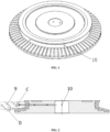
- the water passing holes 10 are circumferentially formed in a base of a special-shaped wheel (i.e., an abrasive wheel) in the prior art. As shown by a mark C in FIG. 2 , cooling may be performed through the several water passing holes 10. However, due to the small number of water passing holes 10 and the limited water output, an internal cooling mode cannot be formed in an entire grinding process. As shown by a mark D in FIG. 2 , the water passing holes 10 are generally formed in a circumference of an axial middle portion of a grinding region of the abrasive wheel and cannot axially cover the entire grinding region, and an axial length of each water passing hole 10 is smaller than an axial length of the grinding region.
- the machining workpiece when a machining workpiece initially contacts the abrasive wheel or will be separated from the abrasive wheel, the machining workpiece cannot be cooled or can only be slightly cooled if a contact point is not in a region axially covered by the water passing holes 10.
- the water passing hole 10 generally is circular, such that the water flow at upper and lower ends of the abrasive wheel is relatively small.
- it is very difficult to cool a small-diameter region of the abrasive wheel due to an adverse effect of a centrifugal force. Since an airflow barrier will be formed during high-speed rotation of the abrasive wheel, the high-speed grinding problem will be more severe under the action of the airflow barrier.
- US 3 683 566 A shows an abrasive wheel comprising water passing grooves axially covering the entire grinding surface, communicating from an inner side of the base with the grinding surface.
- WO 2019/174580 discloses a grinding wheel's groove with a concave portion through which cooling water may flow, but not covering the entire axial grinding length.
- the arc length of each point in the axial direction of the grinding structure may be positively related to the processing amount at the point.
- the technical problem to be solved by the present invention is to provide a special-shaped wheel having a water passing structure positively correlated with a full grinding surface.
- a special-shaped wheel having a water passing structure positively correlated with a full grinding surface includes a base; a grinding layer is attached to an outer wall of the base, and an outer circumferential surface of the grinding layer is a grinding surface; a water inlet is formed in a top surface of the base, and a connection hole for connecting an external device is formed in a bottom surface of the base.
- the special-shaped wheel further includes a plurality of water passing grooves; the plurality of water passing grooves is densely formed around the base by taking a central axis of the base as an axis, communicates an inner side of the base with the grinding surface, and axially covers the entire grinding surface.
- the axial height of an opening of the water passing groove covers the axial height of a grinded region of a machining workpiece, and the total length of accumulated circumferences of the corresponding water passing grooves at respective axial grinding points of the grinding surface is set in positive correlation with the grinding area of the grinding point.
- the above-mentioned positive correlation refers to that a dependent variable increases along with the increase of an independent variable.
- an opening of the water passing groove at each axial point is in positive correlation with a machining allowance (the grinding area of this point). That is, the larger the machining allowance, the larger the opening of the water passing groove.
- the present invention may further include the following improvements.
- the total length of the accumulated circumferences of the corresponding water passing grooves at the respective axial points of the grinding surface is n ⁇ Wi, wherein i refers to the grinding point on the grinding surface, n refers to the number of water passing grooves, and Wi refers to an opening width of the corresponding water passing groove at the grinding point i.
- the grinding area of the point i is set as S, such that the total length of accumulated circumferences (n ⁇ Wi) is proportional to the grinding area S.
- the present invention has the following beneficial effects.
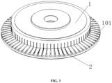
- a special-shaped wheel having a water passing structure positively correlated with a full grinding surface includes a base 1; a grinding layer is attached to an outer wall of the base 1, and an outer circumferential surface of the grinding layer is a grinding surface 101; a water inlet is formed in a top surface of the base 1, and a connection hole for connecting an external device is formed in a bottom surface of the base 1.
- the special-shaped wheel further includes a plurality of water passing grooves 2; the plurality of water passing grooves 2 is densely formed around the base 1 by taking a central axis of the base 1 as an axis, communicates an inner side of the base 1 with the grinding surface 101, and axially covers the entire grinding surface 101.
- the axial height of an opening of the water passing groove 2 covers the axial height of a grinded region of a machining workpiece 10, and the total length of accumulated circumferences of the corresponding water passing grooves 2 at respective axial grinding points of the grinding surface 101 is set in positive correlation with the grinding area of the grinding point.
- the total length of accumulated circumferences of the corresponding water passing grooves 2 at respective axial points of the grinding surface 101 is n ⁇ Wi, wherein i refers to the grinding point on the grinding surface 101, n refers to the number of water passing grooves 2, and Wi refers to an opening width of the corresponding water passing groove 2 at the grinding point i.
- the grinding area of the point i is set as S, such that the total length of accumulated circumferences (n ⁇ Wi) is proportional to the grinding area S.
- the opening of the water passing groove gradually widens from the inner diameter to the outer diameter.
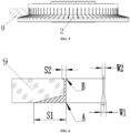
- the grinding area of each axial point is different. As shown in FIG. 6 , the grinding area S1 of the point A is greater than the grinding area S2 of the point B. Since the larger grinding area requires more water for cooling, the openings of the water passing grooves may be correspondingly designed in different sizes according to different water consumptions. In FIG. 6 , as more water is required at the point A than the point B, the opening width W1 of the water passing groove is correspondingly designed to be greater than W2.
- the total length of accumulated circumferences (n ⁇ W) of water supply channels at respective axial points of the grinding surface is set in positive correlation with the grinding area (S) of the points.
- the total length of accumulated circumferences of the corresponding water passing grooves 2 at respective axial points of the grinding surface 101 is n ⁇ Wi, wherein i refers to the grinding point on the grinding surface 101, n refers to the number of water passing grooves 2, and Wi refers to an opening width of the corresponding water passing groove 2 at the grinding point i.
- the opening width of the corresponding water passing groove 2 increases at a position with the large machining allowance, thereby satisfying cooling requirements.
- the special-shaped wheel further includes a base spiral water passing groove 3.
- the base spiral water passing groove 3 is spirally formed around a middle portion of an inner wall of the base 1, and recessed toward an inner side of the base 1.
- the special-shaped wheel further includes a cushion block 4 for connecting an external device.
- the cushion block 4 is of an annular block-shaped structure with a connection hole in the center, and the connection hole of the cushion block 4 is coaxial with a connection hole of the base 1 and the cushion block is fixedly disposed inside the base 1.
- the special-shaped wheel further includes a cushion block spiral water passing groove 5.
- the cushion block spiral water passing groove 5 is spirally formed around a middle portion of an outer wall of the cushion block 4, and recessed toward an inner side of the cushion block 4.
- the special-shaped wheel further includes a water suction component.
- the water suction component 6 is disposed between the cushion block 4 and the base 1, and located at the water inlet of the base 1.
- the water suction component 6 includes an inner ring 601, an outer ring 602 and a plurality of water suction blades 603.
- the outer ring 602 sleeves the inner ring 601, and the water suction blades 603 are transversely connected between the inner ring 601 and the outer ring 602 and circumferentially distributed at intervals.
- the water suction blades 603 can suck the cooling water into the abrasive wheel to increase the water supply amount and support the abrasive wheel.
- a cushion block annular groove 7 is formed in a position, which corresponds to the water suction component 6, of the cushion block 4; a base annular groove 8 is disposed at a position, which corresponds to the water suction component 6, of the base 1; and the inner ring 601 and the outer ring 602 are embedded in the cushion block annular groove 7 and the base annular groove 8 respectively and fixedly connected into one piece.
- each axial point is different.
- arc-shaped water passing grooves are formed around an arc wheel. Since machining allowances at positions close to end surfaces of both ends of the arc wheel are greater than the machining allowance in a middle portion thereof, openings close to the end surfaces of both ends of the arc wheel are wider than the middle portion thereof.
- An arrow in FIG. 13 refers to a flowing path of cooling water.
- arc-shaped water passing grooves are formed around a small-diameter abrasive wheel. Since the machining allowance at a position close to a lower end surface of the small-diameter abrasive wheel is greater than machining allowances in a middle portion and at an upper end thereof, an opening of a water passing groove close to the lower end surface of the small-diameter abrasive wheel is wider than the middle portion and the upper end thereof, and the opening of the water passing groove of the small-diameter abrasive wheel gradually widens from the upper end to the lower end.
- An arrow in FIG. 17 refers to a flowing path of cooling water.
- feed water enters from the water inlet in the end surface of the special-shaped wheel, and the water passing grooves are densely arranged in the circumferential direction to cool the working surface.
- the water passing grooves 2 are axially formed in the full grinding surface of the special-shaped wheel to be less affected by the airflow barrier, and densely arranged to facilitate forming the internal cooling mode.
- the entire grinding surface of the special-shaped wheel can be covered by the cooling water under the forward action of the centrifugal force.
- the opening of the water passing groove 2 of each axial point is in positive correlation with the machining allowance (i.e., the grinding area of the point), that is, the larger the machining allowance, the larger the opening of the water passing groove 2.
Landscapes
- Engineering & Computer Science (AREA)
- Mechanical Engineering (AREA)
- Polishing Bodies And Polishing Tools (AREA)
Description
- The present invention relates to the technical field of abrasive wheel tools, and more particularly to a special-shaped wheel having a water passing structure positively correlated with a full grinding surface.
- As shown in
FIG. 1 and FIG. 2 , severalwater passing holes 10 are circumferentially formed in a base of a special-shaped wheel (i.e., an abrasive wheel) in the prior art. As shown by a mark C inFIG. 2 , cooling may be performed through the severalwater passing holes 10. However, due to the small number ofwater passing holes 10 and the limited water output, an internal cooling mode cannot be formed in an entire grinding process. As shown by a mark D inFIG. 2 , thewater passing holes 10 are generally formed in a circumference of an axial middle portion of a grinding region of the abrasive wheel and cannot axially cover the entire grinding region, and an axial length of eachwater passing hole 10 is smaller than an axial length of the grinding region. Thus, when a machining workpiece initially contacts the abrasive wheel or will be separated from the abrasive wheel, the machining workpiece cannot be cooled or can only be slightly cooled if a contact point is not in a region axially covered by the water passingholes 10. Thewater passing hole 10 generally is circular, such that the water flow at upper and lower ends of the abrasive wheel is relatively small. In an external cooling mode, it is very difficult to cool a small-diameter region of the abrasive wheel due to an adverse effect of a centrifugal force. Since an airflow barrier will be formed during high-speed rotation of the abrasive wheel, the high-speed grinding problem will be more severe under the action of the airflow barrier. -
US 3 683 566 A shows an abrasive wheel comprising water passing grooves axially covering the entire grinding surface, communicating from an inner side of the base with the grinding surface. Furthermore,WO 2019/174580 discloses a grinding wheel's groove with a concave portion through which cooling water may flow, but not covering the entire axial grinding length. The arc length of each point in the axial direction of the grinding structure may be positively related to the processing amount at the point. - In order to overcome the shortcomings in the prior art, the technical problem to be solved by the present invention is to provide a special-shaped wheel having a water passing structure positively correlated with a full grinding surface.
- In order to solve the above technical problem, the technical solution of the present invention is as follows: a special-shaped wheel having a water passing structure positively correlated with a full grinding surface includes a base; a grinding layer is attached to an outer wall of the base, and an outer circumferential surface of the grinding layer is a grinding surface; a water inlet is formed in a top surface of the base, and a connection hole for connecting an external device is formed in a bottom surface of the base. The special-shaped wheel further includes a plurality of water passing grooves; the plurality of water passing grooves is densely formed around the base by taking a central axis of the base as an axis, communicates an inner side of the base with the grinding surface, and axially covers the entire grinding surface. That is, the axial height of an opening of the water passing groove covers the axial height of a grinded region of a machining workpiece, and the total length of accumulated circumferences of the corresponding water passing grooves at respective axial grinding points of the grinding surface is set in positive correlation with the grinding area of the grinding point.
- The above-mentioned positive correlation refers to that a dependent variable increases along with the increase of an independent variable. In other words, an opening of the water passing groove at each axial point is in positive correlation with a machining allowance (the grinding area of this point). That is, the larger the machining allowance, the larger the opening of the water passing groove.
- Based on the above technical solution, the present invention may further include the following improvements.
- Further, the total length of the accumulated circumferences of the corresponding water passing grooves at the respective axial points of the grinding surface is n×Wi, wherein i refers to the grinding point on the grinding surface, n refers to the number of water passing grooves, and Wi refers to an opening width of the corresponding water passing groove at the grinding point i.
- The grinding area of the point i is set as S, such that the total length of accumulated circumferences (n×Wi) is proportional to the grinding area S.
- The present invention has the following beneficial effects.
- 1. Feed water enters from the water inlet in an end surface of the special-shaped wheel, and the water passing grooves are densely formed in the circumferential direction to cool a working surface.
- 2. The water passing grooves are axially formed in the full grinding surface of the special-shaped wheel to be less affected by the airflow barrier, and densely arranged to facilitate forming the internal cooling mode.
- 3. The entire grinding surface of the special-shaped wheel can be covered by cooling water under the forward action of a centrifugal force.
- 4. The opening of the water passing groove of each axial point is in positive correlation with the machining allowance (i.e., the grinding area of the point), that is, the larger the machining allowance, the larger the opening of the water passing groove.
- 5. The technical problem in which the cooling water is difficult to be applied to the full grinding surface in the overall one-time manufacturing is solved, thereby greatly reducing the manufacturing cost.
-
-
FIG. 1 is a schematic structural diagram of a special-shaped wheel in the prior art according to an embodiment of the present invention; -
FIG. 2 is a schematic diagram of a water passing hole of a special-shaped wheel in the prior art according to an embodiment of the present invention; -
FIG. 3 is a schematic structural diagram of a special-shaped wheel having a water passing structure positively correlated with a full grinding surface according to an embodiment of the present invention; -
FIG. 4 is a schematic structural diagram of a cushion block according to an embodiment of the present invention; -
FIG. 5 is a schematic structural diagram of a water passing groove according to an embodiment of the present invention; -
FIG. 6 is a principle diagram in which a water passing groove is formed according to an embodiment of the present invention; -
FIG. 7 is a schematic structural diagram of a spiral water passing groove according to an embodiment of the present invention; -
FIG. 8 is a top view of a water suction component according to an embodiment of the present invention; -
FIG. 9 is a schematic structural diagram of a water suction component according to an embodiment of the present invention; -
FIG. 10 is a schematic diagram of connection between a water suction component and a base according to an embodiment of the present invention; -
FIG. 11 is a schematic diagram of an annular groove according to an embodiment of the present invention; -
FIG. 12 is a schematic structural diagram of a water passing groove of an arc wheel according to an embodiment of the present invention; -
FIG. 13 is a schematic diagram of cooling water flowing in an arc wheel according to an embodiment of the present invention; -
FIG. 14 is a sectional view of an arc wheel according to an embodiment of the present invention; -
FIG. 15 is a schematic structural diagram in which a water passing groove of a small-diameter abrasive wheel is formed according to an embodiment of the present invention; -
FIG. 16 is a sectional view of a small-diameter abrasive wheel according to an embodiment of the present invention; and -
FIG. 17 is a schematic diagram of cooling water flowing in a small-diameter abrasive wheel according to an embodiment of the present invention. - In the drawings, components represented by different numerals are listed as follows:
1. base; 2. water passing groove; 3. base spiral water passing groove; 4. cushion block; 5. cushion block spiral water passing groove; 6. water suction component; 7. cushion block annular groove; 8. base annular groove; 9. machining workpiece; 10. water passing hole; 101. grinding surface; 601. inner ring; 602. outer ring; and 603. water suction blade. - Principles and features of the present invention will be described below in combination with the accompanying drawings. Embodiments are merely used to explain the present invention rather than limit the scope of the present invention.
- As shown in
FIGs. 3-5 , a special-shaped wheel having a water passing structure positively correlated with a full grinding surface includes abase 1; a grinding layer is attached to an outer wall of thebase 1, and an outer circumferential surface of the grinding layer is agrinding surface 101; a water inlet is formed in a top surface of thebase 1, and a connection hole for connecting an external device is formed in a bottom surface of thebase 1. The special-shaped wheel further includes a plurality ofwater passing grooves 2; the plurality ofwater passing grooves 2 is densely formed around thebase 1 by taking a central axis of thebase 1 as an axis, communicates an inner side of thebase 1 with the grindingsurface 101, and axially covers the entire grindingsurface 101. That is, the axial height of an opening of thewater passing groove 2 covers the axial height of a grinded region of amachining workpiece 10, and the total length of accumulated circumferences of the correspondingwater passing grooves 2 at respective axial grinding points of the grindingsurface 101 is set in positive correlation with the grinding area of the grinding point. - Specifically, the total length of accumulated circumferences of the corresponding
water passing grooves 2 at respective axial points of the grindingsurface 101 is n×Wi, wherein i refers to the grinding point on the grindingsurface 101, n refers to the number ofwater passing grooves 2, and Wi refers to an opening width of the correspondingwater passing groove 2 at the grinding point i. - The grinding area of the point i is set as S, such that the total length of accumulated circumferences (n×Wi) is proportional to the grinding area S.
- When the machining allowance gradually increases from an inner diameter to an outer diameter, the opening of the water passing groove gradually widens from the inner diameter to the outer diameter.
- For different shapes of machining
workpieces 10, the grinding area of each axial point is different. As shown inFIG. 6 , the grinding area S1 of the point A is greater than the grinding area S2 of the point B. Since the larger grinding area requires more water for cooling, the openings of the water passing grooves may be correspondingly designed in different sizes according to different water consumptions. InFIG. 6 , as more water is required at the point A than the point B, the opening width W1 of the water passing groove is correspondingly designed to be greater than W2. The total length of accumulated circumferences (n×W) of water supply channels at respective axial points of the grinding surface is set in positive correlation with the grinding area (S) of the points. - Optionally, as an embodiment of the present invention, the total length of accumulated circumferences of the corresponding
water passing grooves 2 at respective axial points of the grindingsurface 101 is n×Wi, wherein i refers to the grinding point on the grindingsurface 101, n refers to the number ofwater passing grooves 2, and Wi refers to an opening width of the correspondingwater passing groove 2 at the grinding point i. - In the above embodiment, the opening width of the corresponding
water passing groove 2 increases at a position with the large machining allowance, thereby satisfying cooling requirements. - Optionally, as an embodiment of the present invention, as shown in
FIG. 7 , the special-shaped wheel further includes a base spiralwater passing groove 3. The base spiralwater passing groove 3 is spirally formed around a middle portion of an inner wall of thebase 1, and recessed toward an inner side of thebase 1. - In the above embodiment, when the special-shaped wheel is rotated, a part of water axially rises under the action of the spiral groove to be supplied to a position with a larger grinding (cutting) area.
- Optionally, as an embodiment of the present invention, as shown in
FIG. 4 , the special-shaped wheel further includes acushion block 4 for connecting an external device. Thecushion block 4 is of an annular block-shaped structure with a connection hole in the center, and the connection hole of thecushion block 4 is coaxial with a connection hole of thebase 1 and the cushion block is fixedly disposed inside thebase 1. - Optionally, as an embodiment of the present invention, as shown in
FIG. 7 , the special-shaped wheel further includes a cushion block spiral water passing groove 5. The cushion block spiral water passing groove 5 is spirally formed around a middle portion of an outer wall of thecushion block 4, and recessed toward an inner side of thecushion block 4. - In the above embodiment, when the special-shaped wheel is rotated, a part of water axially rises under the action of the spiral groove to be supplied to a position with a larger grinding (cutting) area.
- Optionally, as an embodiment of the present invention, as shown in
FIGs. 8-10 , the special-shaped wheel further includes a water suction component. Thewater suction component 6 is disposed between thecushion block 4 and thebase 1, and located at the water inlet of thebase 1. Thewater suction component 6 includes aninner ring 601, anouter ring 602 and a plurality ofwater suction blades 603. Theouter ring 602 sleeves theinner ring 601, and thewater suction blades 603 are transversely connected between theinner ring 601 and theouter ring 602 and circumferentially distributed at intervals. - In the above embodiment, the
water suction blades 603 can suck the cooling water into the abrasive wheel to increase the water supply amount and support the abrasive wheel. - Optionally, as an embodiment of the present invention, as shown in
FIG. 11 , a cushion blockannular groove 7 is formed in a position, which corresponds to thewater suction component 6, of thecushion block 4; a baseannular groove 8 is disposed at a position, which corresponds to thewater suction component 6, of thebase 1; and theinner ring 601 and theouter ring 602 are embedded in the cushion blockannular groove 7 and the baseannular groove 8 respectively and fixedly connected into one piece. - For different shapes of machining
workpieces 10, the grinding area of each axial point is different. As shown inFIGs. 12-14 , for example, arc-shaped water passing grooves are formed around an arc wheel. Since machining allowances at positions close to end surfaces of both ends of the arc wheel are greater than the machining allowance in a middle portion thereof, openings close to the end surfaces of both ends of the arc wheel are wider than the middle portion thereof. An arrow inFIG. 13 refers to a flowing path of cooling water. - As shown in
FIGs. 15-17 , for example, arc-shaped water passing grooves are formed around a small-diameter abrasive wheel. Since the machining allowance at a position close to a lower end surface of the small-diameter abrasive wheel is greater than machining allowances in a middle portion and at an upper end thereof, an opening of a water passing groove close to the lower end surface of the small-diameter abrasive wheel is wider than the middle portion and the upper end thereof, and the opening of the water passing groove of the small-diameter abrasive wheel gradually widens from the upper end to the lower end. An arrow inFIG. 17 refers to a flowing path of cooling water. - In the present invention, feed water enters from the water inlet in the end surface of the special-shaped wheel, and the water passing grooves are densely arranged in the circumferential direction to cool the working surface. The
water passing grooves 2 are axially formed in the full grinding surface of the special-shaped wheel to be less affected by the airflow barrier, and densely arranged to facilitate forming the internal cooling mode. The entire grinding surface of the special-shaped wheel can be covered by the cooling water under the forward action of the centrifugal force. The opening of thewater passing groove 2 of each axial point is in positive correlation with the machining allowance (i.e., the grinding area of the point), that is, the larger the machining allowance, the larger the opening of thewater passing groove 2. The technical problem in which the cooling water is difficult to be applied to the full grinding surface in the overall one-time manufacturing is solved, thereby greatly reducing the manufacturing cost. - The foregoing descriptions are merely preferred embodiments of the present invention, and are not intended to limit the present invention. Within the spirit and principles of the present invention, any modifications, equivalent substitutions, improvements, and the like are within the protection scope of the present invention.
Claims (7)
- A special-shaped wheel having a water passing structure positively correlated with a full grinding surface, comprising: a base (1), wherein a grinding layer is attached to an outer wall of the base (1), an outer circumferential surface of the grinding layer is a grinding surface (101), a water inlet is formed in a top surface of the base (1), and a connection hole for connecting an external device is formed in a bottom surface of the base (1); and the special-shaped wheel further comprises a plurality of water passing grooves (2), wherein the plurality of water passing grooves (2) is densely formed around the base (1) by taking a central axis of the base (1) as an axis, communicates an inner side of the base (1) with the grinding surface (101), and axially covers the entire grinding surface (101); and the total length of accumulated circumferences of the corresponding water passing grooves (2) at respective axial grinding points of the grinding surface (101) is set in positive correlation with the grinding area of the grinding point.
- The special-shaped wheel according to claim 1, wherein the total length of accumulated circumferences of the corresponding water passing grooves (2) at respective axial points of the grinding surface (101) is n×Wi, wherein i refers to the grinding point on the grinding surface (101), n refers to the number of water passing grooves (2), and Wi refers to an opening width of the corresponding water passing groove (2) at the grinding point i.
- The special-shaped wheel according to claim 1, further comprising: a base spiral water passing groove (3), wherein the base spiral water passing groove (3) is spirally formed around a middle portion of an inner wall of the base (1), and recessed toward an inner side of the base (1).
- The special-shaped wheel according to any one of claims 1 to 3, further comprising: a cushion block (4) for connecting an external device, wherein the cushion block (4) is of an annular block-shaped structure with a connection hole in the center, the connection hole of the cushion block (4) is coaxial with a connection hole of the base (1), and the cushion block (4) is fixedly disposed inside the base (1).
- The special-shaped wheel according to claim 4, further comprising: a cushion block spiral water passing groove (5), wherein the cushion block spiral water passing groove (5) is spirally formed around a middle portion of an outer wall of the cushion block (4), and recessed toward an inner side of the cushion block (4).
- The special-shaped wheel according to claim 4, further comprising: a water suction component, wherein the water suction component (6) is disposed between the cushion block (4) and the base (1), and located at the water inlet of the base (1); the water suction component (6) comprises an inner ring (601), an outer ring (602) and a plurality of water suction blades (603); the outer ring (602) sleeves the inner ring (601), and the water suction blades (603) are transversely connected between the inner ring (601) and the outer ring (602) and circumferentially distributed at intervals.
- The special-shaped wheel according to claim 6, wherein a cushion block annular groove (7) is formed in a position, which corresponds to the water suction component (6), of the cushion block (4); a base annular groove (8) is formed in a position, which corresponds to the water suction component (6), of the base (1); and the inner ring (601) and the outer ring (602) are embedded in the cushion block annular groove (7) and the base annular groove (8) respectively and fixedly connected into one piece.
Applications Claiming Priority (3)
| Application Number | Priority Date | Filing Date | Title |
|---|---|---|---|
| CN202020813772.8U CN212218224U (en) | 2020-05-15 | 2020-05-15 | Special-shaped wheel with positive correlation water flowing structure of full-grinding surface |
| CN202010414824.9A CN111590476B (en) | 2020-05-15 | 2020-05-15 | A special-shaped wheel with a positively correlated water-through structure on the entire grinding surface |
| PCT/CN2021/093493 WO2021228170A1 (en) | 2020-05-15 | 2021-05-13 | Special-shaped wheel having positive correlation water passing structure for full-grinding surface |
Publications (3)
| Publication Number | Publication Date |
|---|---|
| EP4151364A1 EP4151364A1 (en) | 2023-03-22 |
| EP4151364A4 EP4151364A4 (en) | 2024-05-15 |
| EP4151364B1 true EP4151364B1 (en) | 2024-11-13 |
Family
ID=78525339
Family Applications (1)
| Application Number | Title | Priority Date | Filing Date |
|---|---|---|---|
| EP21804106.9A Active EP4151364B1 (en) | 2020-05-15 | 2021-05-13 | Special-shaped wheel having positive correlation water passing structure for full-grinding surface |
Country Status (2)
| Country | Link |
|---|---|
| EP (1) | EP4151364B1 (en) |
| WO (1) | WO2021228170A1 (en) |
Families Citing this family (3)
| Publication number | Priority date | Publication date | Assignee | Title |
|---|---|---|---|---|
| CN118269242A (en) * | 2022-12-30 | 2024-07-02 | 桂林磨院材料科技有限公司 | Semiconductor dicing soft knife |
| CN120828370A (en) * | 2024-04-17 | 2025-10-24 | 桂林磨院材料科技有限公司 | Cup-shaped polishing wheel with functional plate |
| CN120828368A (en) * | 2024-04-17 | 2025-10-24 | 桂林磨院材料科技有限公司 | Electroplated single-layer diamond anti-deformation grinding part, grinding ring and special-shaped grinding wheel |
Family Cites Families (7)
| Publication number | Priority date | Publication date | Assignee | Title |
|---|---|---|---|---|
| US3683566A (en) * | 1970-10-05 | 1972-08-15 | Klemens C Walters | Segmented grinding wheel assembly |
| JP2005081523A (en) * | 2003-09-11 | 2005-03-31 | Hitachi Zosen Corp | Polishing device, polishing tool and grinding wheel base |
| CN206732729U (en) * | 2017-03-17 | 2017-12-12 | 桂林创源金刚石有限公司 | A kind of diamond abnormity emery wheel and vertical processing cooling system |
| ES2983497T3 (en) * | 2018-03-12 | 2024-10-23 | Guilin Champion Union Diamond Co Ltd | Abrasive tool and manufacturing process thereof |
| CN110948404B (en) * | 2019-12-27 | 2025-03-11 | 桂林创源金刚石有限公司 | A combined chamfering device |
| CN111590476B (en) * | 2020-05-15 | 2025-09-12 | 桂林创源金刚石有限公司 | A special-shaped wheel with a positively correlated water-through structure on the entire grinding surface |
| CN212218224U (en) * | 2020-05-15 | 2020-12-25 | 桂林创源金刚石有限公司 | Special-shaped wheel with positive correlation water flowing structure of full-grinding surface |
-
2021
- 2021-05-13 WO PCT/CN2021/093493 patent/WO2021228170A1/en not_active Ceased
- 2021-05-13 EP EP21804106.9A patent/EP4151364B1/en active Active
Also Published As
| Publication number | Publication date |
|---|---|
| EP4151364A1 (en) | 2023-03-22 |
| WO2021228170A1 (en) | 2021-11-18 |
| EP4151364A4 (en) | 2024-05-15 |
Similar Documents
| Publication | Publication Date | Title |
|---|---|---|
| EP4151364A1 (en) | Special-shaped wheel having positive correlation water passing structure for full-grinding surface | |
| US8858125B2 (en) | Tool assembly for removing material from a work-piece | |
| US12220789B2 (en) | High-rotational speed cup-shaped grinding wheel | |
| TW201927477A (en) | Nozzle, nozzle module, and machine tools provided with them | |
| RU2566233C2 (en) | Through adapter for lubricating and cooling emulsion for use with tools of machines with hollow spindle | |
| CN212218224U (en) | Special-shaped wheel with positive correlation water flowing structure of full-grinding surface | |
| CN111590476B (en) | A special-shaped wheel with a positively correlated water-through structure on the entire grinding surface | |
| JP4407975B2 (en) | Ball end mill | |
| EP4194146B1 (en) | High-speed cup-shaped wheel cooling structure | |
| KR20240119252A (en) | Drill body of an indexable insert drill and indexable insert drill comprising such drill body | |
| JP4057863B2 (en) | Deep hole cutting equipment | |
| JP2023532777A5 (en) | ||
| CN214489982U (en) | Anti-deformation glass drilling chamfering grinding tool | |
| CN107877370B (en) | Double-end main shaft | |
| CN110614400A (en) | Miniature cutter with coolant liquid delivery hole | |
| CN211540892U (en) | Grinding wheel | |
| KR20230001750A (en) | Milling cutter | |
| CN214053814U (en) | A helical milling cutter with vertically mounted inserts | |
| CN223671545U (en) | Glass punching cutter assembly and glass punching device | |
| CN222608106U (en) | Knuckle sphere processing reaming ball bores compound cutter | |
| JP4390339B2 (en) | Coolant discharge device for machine tools | |
| JP6032466B2 (en) | Dicing machine | |
| EP3492760B1 (en) | Ball bearing | |
| JP3219215U (en) | Coolant collet assembly | |
| JP3742002B2 (en) | Cooling structure for jigs for processing machines |
Legal Events
| Date | Code | Title | Description |
|---|---|---|---|
| STAA | Information on the status of an ep patent application or granted ep patent |
Free format text: STATUS: THE INTERNATIONAL PUBLICATION HAS BEEN MADE |
|
| PUAI | Public reference made under article 153(3) epc to a published international application that has entered the european phase |
Free format text: ORIGINAL CODE: 0009012 |
|
| STAA | Information on the status of an ep patent application or granted ep patent |
Free format text: STATUS: REQUEST FOR EXAMINATION WAS MADE |
|
| 17P | Request for examination filed |
Effective date: 20221116 |
|
| AK | Designated contracting states |
Kind code of ref document: A1 Designated state(s): AL AT BE BG CH CY CZ DE DK EE ES FI FR GB GR HR HU IE IS IT LI LT LU LV MC MK MT NL NO PL PT RO RS SE SI SK SM TR |
|
| DAV | Request for validation of the european patent (deleted) | ||
| DAX | Request for extension of the european patent (deleted) | ||
| A4 | Supplementary search report drawn up and despatched |
Effective date: 20240415 |
|
| RIC1 | Information provided on ipc code assigned before grant |
Ipc: B24D 5/10 20060101ALI20240409BHEP Ipc: B24D 7/10 20060101AFI20240409BHEP |
|
| GRAP | Despatch of communication of intention to grant a patent |
Free format text: ORIGINAL CODE: EPIDOSNIGR1 |
|
| STAA | Information on the status of an ep patent application or granted ep patent |
Free format text: STATUS: GRANT OF PATENT IS INTENDED |
|
| INTG | Intention to grant announced |
Effective date: 20240808 |
|
| GRAS | Grant fee paid |
Free format text: ORIGINAL CODE: EPIDOSNIGR3 |
|
| GRAA | (expected) grant |
Free format text: ORIGINAL CODE: 0009210 |
|
| STAA | Information on the status of an ep patent application or granted ep patent |
Free format text: STATUS: THE PATENT HAS BEEN GRANTED |
|
| AK | Designated contracting states |
Kind code of ref document: B1 Designated state(s): AL AT BE BG CH CY CZ DE DK EE ES FI FR GB GR HR HU IE IS IT LI LT LU LV MC MK MT NL NO PL PT RO RS SE SI SK SM TR |
|
| REG | Reference to a national code |
Ref country code: GB Ref legal event code: FG4D |
|
| REG | Reference to a national code |
Ref country code: CH Ref legal event code: EP |
|
| REG | Reference to a national code |
Ref country code: DE Ref legal event code: R096 Ref document number: 602021021874 Country of ref document: DE |
|
| REG | Reference to a national code |
Ref country code: IE Ref legal event code: FG4D |
|
| REG | Reference to a national code |
Ref country code: LT Ref legal event code: MG9D |
|
| REG | Reference to a national code |
Ref country code: NL Ref legal event code: MP Effective date: 20241113 |
|
| PG25 | Lapsed in a contracting state [announced via postgrant information from national office to epo] |
Ref country code: PT Free format text: LAPSE BECAUSE OF FAILURE TO SUBMIT A TRANSLATION OF THE DESCRIPTION OR TO PAY THE FEE WITHIN THE PRESCRIBED TIME-LIMIT Effective date: 20250313 Ref country code: HR Free format text: LAPSE BECAUSE OF FAILURE TO SUBMIT A TRANSLATION OF THE DESCRIPTION OR TO PAY THE FEE WITHIN THE PRESCRIBED TIME-LIMIT Effective date: 20241113 Ref country code: IS Free format text: LAPSE BECAUSE OF FAILURE TO SUBMIT A TRANSLATION OF THE DESCRIPTION OR TO PAY THE FEE WITHIN THE PRESCRIBED TIME-LIMIT Effective date: 20250313 |
|
| PG25 | Lapsed in a contracting state [announced via postgrant information from national office to epo] |
Ref country code: FI Free format text: LAPSE BECAUSE OF FAILURE TO SUBMIT A TRANSLATION OF THE DESCRIPTION OR TO PAY THE FEE WITHIN THE PRESCRIBED TIME-LIMIT Effective date: 20241113 Ref country code: NL Free format text: LAPSE BECAUSE OF FAILURE TO SUBMIT A TRANSLATION OF THE DESCRIPTION OR TO PAY THE FEE WITHIN THE PRESCRIBED TIME-LIMIT Effective date: 20241113 |
|
| REG | Reference to a national code |
Ref country code: AT Ref legal event code: MK05 Ref document number: 1741325 Country of ref document: AT Kind code of ref document: T Effective date: 20241113 |
|
| PG25 | Lapsed in a contracting state [announced via postgrant information from national office to epo] |
Ref country code: BG Free format text: LAPSE BECAUSE OF FAILURE TO SUBMIT A TRANSLATION OF THE DESCRIPTION OR TO PAY THE FEE WITHIN THE PRESCRIBED TIME-LIMIT Effective date: 20241113 |
|
| PG25 | Lapsed in a contracting state [announced via postgrant information from national office to epo] |
Ref country code: ES Free format text: LAPSE BECAUSE OF FAILURE TO SUBMIT A TRANSLATION OF THE DESCRIPTION OR TO PAY THE FEE WITHIN THE PRESCRIBED TIME-LIMIT Effective date: 20241113 |
|
| PG25 | Lapsed in a contracting state [announced via postgrant information from national office to epo] |
Ref country code: NO Free format text: LAPSE BECAUSE OF FAILURE TO SUBMIT A TRANSLATION OF THE DESCRIPTION OR TO PAY THE FEE WITHIN THE PRESCRIBED TIME-LIMIT Effective date: 20250213 |
|
| PG25 | Lapsed in a contracting state [announced via postgrant information from national office to epo] |
Ref country code: AT Free format text: LAPSE BECAUSE OF FAILURE TO SUBMIT A TRANSLATION OF THE DESCRIPTION OR TO PAY THE FEE WITHIN THE PRESCRIBED TIME-LIMIT Effective date: 20241113 Ref country code: GR Free format text: LAPSE BECAUSE OF FAILURE TO SUBMIT A TRANSLATION OF THE DESCRIPTION OR TO PAY THE FEE WITHIN THE PRESCRIBED TIME-LIMIT Effective date: 20250214 Ref country code: LV Free format text: LAPSE BECAUSE OF FAILURE TO SUBMIT A TRANSLATION OF THE DESCRIPTION OR TO PAY THE FEE WITHIN THE PRESCRIBED TIME-LIMIT Effective date: 20241113 |
|
| PG25 | Lapsed in a contracting state [announced via postgrant information from national office to epo] |
Ref country code: PL Free format text: LAPSE BECAUSE OF FAILURE TO SUBMIT A TRANSLATION OF THE DESCRIPTION OR TO PAY THE FEE WITHIN THE PRESCRIBED TIME-LIMIT Effective date: 20241113 |
|
| PG25 | Lapsed in a contracting state [announced via postgrant information from national office to epo] |
Ref country code: RS Free format text: LAPSE BECAUSE OF FAILURE TO SUBMIT A TRANSLATION OF THE DESCRIPTION OR TO PAY THE FEE WITHIN THE PRESCRIBED TIME-LIMIT Effective date: 20250213 |
|
| PG25 | Lapsed in a contracting state [announced via postgrant information from national office to epo] |
Ref country code: SM Free format text: LAPSE BECAUSE OF FAILURE TO SUBMIT A TRANSLATION OF THE DESCRIPTION OR TO PAY THE FEE WITHIN THE PRESCRIBED TIME-LIMIT Effective date: 20241113 |
|
| PGFP | Annual fee paid to national office [announced via postgrant information from national office to epo] |
Ref country code: DE Payment date: 20250519 Year of fee payment: 5 |
|
| PG25 | Lapsed in a contracting state [announced via postgrant information from national office to epo] |
Ref country code: DK Free format text: LAPSE BECAUSE OF FAILURE TO SUBMIT A TRANSLATION OF THE DESCRIPTION OR TO PAY THE FEE WITHIN THE PRESCRIBED TIME-LIMIT Effective date: 20241113 |
|
| PGFP | Annual fee paid to national office [announced via postgrant information from national office to epo] |
Ref country code: IT Payment date: 20250530 Year of fee payment: 5 |
|
| PG25 | Lapsed in a contracting state [announced via postgrant information from national office to epo] |
Ref country code: EE Free format text: LAPSE BECAUSE OF FAILURE TO SUBMIT A TRANSLATION OF THE DESCRIPTION OR TO PAY THE FEE WITHIN THE PRESCRIBED TIME-LIMIT Effective date: 20241113 |
|
| PG25 | Lapsed in a contracting state [announced via postgrant information from national office to epo] |
Ref country code: RO Free format text: LAPSE BECAUSE OF FAILURE TO SUBMIT A TRANSLATION OF THE DESCRIPTION OR TO PAY THE FEE WITHIN THE PRESCRIBED TIME-LIMIT Effective date: 20241113 |
|
| PG25 | Lapsed in a contracting state [announced via postgrant information from national office to epo] |
Ref country code: SK Free format text: LAPSE BECAUSE OF FAILURE TO SUBMIT A TRANSLATION OF THE DESCRIPTION OR TO PAY THE FEE WITHIN THE PRESCRIBED TIME-LIMIT Effective date: 20241113 |
|
| PG25 | Lapsed in a contracting state [announced via postgrant information from national office to epo] |
Ref country code: CZ Free format text: LAPSE BECAUSE OF FAILURE TO SUBMIT A TRANSLATION OF THE DESCRIPTION OR TO PAY THE FEE WITHIN THE PRESCRIBED TIME-LIMIT Effective date: 20241113 |
|
| REG | Reference to a national code |
Ref country code: DE Ref legal event code: R097 Ref document number: 602021021874 Country of ref document: DE |
|
| PG25 | Lapsed in a contracting state [announced via postgrant information from national office to epo] |
Ref country code: SE Free format text: LAPSE BECAUSE OF FAILURE TO SUBMIT A TRANSLATION OF THE DESCRIPTION OR TO PAY THE FEE WITHIN THE PRESCRIBED TIME-LIMIT Effective date: 20241113 |
|
| PLBE | No opposition filed within time limit |
Free format text: ORIGINAL CODE: 0009261 |
|
| STAA | Information on the status of an ep patent application or granted ep patent |
Free format text: STATUS: NO OPPOSITION FILED WITHIN TIME LIMIT |
|
| 26N | No opposition filed |
Effective date: 20250814 |
|
| REG | Reference to a national code |
Ref country code: CH Ref legal event code: H13 Free format text: ST27 STATUS EVENT CODE: U-0-0-H10-H13 (AS PROVIDED BY THE NATIONAL OFFICE) Effective date: 20251223 |
|
| PG25 | Lapsed in a contracting state [announced via postgrant information from national office to epo] |
Ref country code: LU Free format text: LAPSE BECAUSE OF NON-PAYMENT OF DUE FEES Effective date: 20250513 |
|
| PG25 | Lapsed in a contracting state [announced via postgrant information from national office to epo] |
Ref country code: CH Free format text: LAPSE BECAUSE OF NON-PAYMENT OF DUE FEES Effective date: 20250531 |
|
| GBPC | Gb: european patent ceased through non-payment of renewal fee |
Effective date: 20250513 |
|
| REG | Reference to a national code |
Ref country code: BE Ref legal event code: MM Effective date: 20250531 |
|
| PG25 | Lapsed in a contracting state [announced via postgrant information from national office to epo] |
Ref country code: MC Free format text: LAPSE BECAUSE OF FAILURE TO SUBMIT A TRANSLATION OF THE DESCRIPTION OR TO PAY THE FEE WITHIN THE PRESCRIBED TIME-LIMIT Effective date: 20241113 |
|
| PG25 | Lapsed in a contracting state [announced via postgrant information from national office to epo] |
Ref country code: GB Free format text: LAPSE BECAUSE OF NON-PAYMENT OF DUE FEES Effective date: 20250513 |
|
| PG25 | Lapsed in a contracting state [announced via postgrant information from national office to epo] |
Ref country code: IE Free format text: LAPSE BECAUSE OF NON-PAYMENT OF DUE FEES Effective date: 20250513 |
|
| PG25 | Lapsed in a contracting state [announced via postgrant information from national office to epo] |
Ref country code: BE Free format text: LAPSE BECAUSE OF NON-PAYMENT OF DUE FEES Effective date: 20250531 |
|
| PG25 | Lapsed in a contracting state [announced via postgrant information from national office to epo] |
Ref country code: FR Free format text: LAPSE BECAUSE OF NON-PAYMENT OF DUE FEES Effective date: 20250531 |