JP3742002B2 - Cooling structure for jigs for processing machines - Google Patents
Cooling structure for jigs for processing machines Download PDFInfo
- Publication number
- JP3742002B2 JP3742002B2 JP2001376339A JP2001376339A JP3742002B2 JP 3742002 B2 JP3742002 B2 JP 3742002B2 JP 2001376339 A JP2001376339 A JP 2001376339A JP 2001376339 A JP2001376339 A JP 2001376339A JP 3742002 B2 JP3742002 B2 JP 3742002B2
- Authority
- JP
- Japan
- Prior art keywords
- cooling
- flow path
- air
- cooling structure
- machining shaft
- Prior art date
- Legal status (The legal status is an assumption and is not a legal conclusion. Google has not performed a legal analysis and makes no representation as to the accuracy of the status listed.)
- Expired - Fee Related
Links
Images


Landscapes
- Jigs For Machine Tools (AREA)
- Gear Processing (AREA)
Description
【0001】
【発明の属する技術分野】
本発明は、冷却用の空気を流通させる冷却流路が内部に形成された加工機用治具の冷却構造に関する。
【0002】
【従来の技術】
冷却用の空気を流通させる冷却流路が内部に形成された加工機用治具の冷却構造に関する技術として、例えば、特開2001−47311号公報に開示されたものがある。この公報には、切削油を使用せずに切削を行うドライカット方式を採用した場合に、加工軸に発生する熱歪みの影響が大きくなるため、ワークを支持する加工軸の内部に冷却用の空気を流通させる冷却流路を形成することで、熱歪みを抑えて加工精度を確保するホブ盤が記載されている。
【0003】
【発明が解決しようとする課題】
しかしながら、切削油を使用せずに切削を行うドライカット方式を採用した場合には、上記公報のように加工軸の内部に冷却流路を形成して冷却用の空気を流通させたとしても十分に冷却ができない場合があった。特に、平歯車の歯切り加工において加工効率を向上させるためワークを複数積み重ねた状態で一度に加工する積み重ね加工を行うと、当然のことながら加工中にワークおよびワークを支持する治具等の温度が一層上昇することになり、上記した公報の冷却構造では温度上昇を十分に抑えることができない。
【0004】
したがって、本発明の目的は、加工中の温度上昇を十分に抑えることができる加工機用治具の冷却構造の提供を目的とする。
【0005】
【課題を解決するための手段】
上記目的を達成するために、本発明の請求項1記載の加工機用治具の冷却構造は、冷却用の空気を流通させる冷却流路(例えば実施の形態における冷却流路14a,15a)が内部に形成されたものであって、前記冷却流路を形成する内壁(例えば実施の形態における内壁14b,15b)には、表面積を拡大させる冷却フィン部(例えば実施の形態における冷却フィン部24)が設けられており、前記冷却フィン部は、前記内壁に圧入された複数の環状部材(例えば実施の形態における環状部材25)からなっていて、前記環状部材は、一部が切断されかつ斜めに折り曲げられた形状の傾斜部(例えば実施の形態における傾斜部31)を有しており、複数の前記環状部材が、互いの傾斜部同士が螺旋状をなすように配置されていることを特徴としている。
【0006】
このように、冷却流路を形成する内壁には、表面積を拡大させる冷却フィン部が設けられているため、流通する冷却用の空気による冷却効率を向上させることができる。
また、冷却フィン部が内壁に圧入される複数の環状部材からなるため、複数の環状部材を別途作製して圧入すれば良く、特に冷却流路の断面積を大きくとれる場合であって大きな冷却フィン部を形成する場合の製造が容易となる。
さらに、複数の環状部材が、一部が切断されかつ斜めに折り曲げられた形状の傾斜部をそれぞれ有し、それぞれの傾斜部同士が螺旋状をなすように配置されているため、傾斜部で案内される冷却用の空気が螺旋状に流れることになり、この空気による冷却効率をさらに向上させることができる。
【0011】
本発明の請求項2記載の加工機用治具の冷却構造は、請求項1記載のものに関して、前記環状部材はアルミニウムからなることを特徴としている。
【0012】
このように、環状部材は熱伝導率の高いアルミニウムからなるため、流通する冷却用の空気による冷却効率をさらに向上させることができる。
【0017】
【発明の実施の形態】
第1参考例の加工機用治具の冷却構造を図1〜図3を参照して以下に説明する。
【0018】
第1参考例の加工機用治具は、切削油を使用せずに切削を行うドライカット方式であって、しかも加工効率を向上させるためワークを複数段に積み重ねた状態で一度に歯切り加工する積み重ね加工を行う歯切り盤(ホブ盤)用のもので、具体的には、図1に示すように円環状のワーク11を複数重ね合わせた状態でその内周側を嵌合させ心出ししつつ支持する加工軸12である。
【0019】
この加工軸12は、その下端部が歯切り盤の支持台13に上側から挿入された状態で把持されるとともに軸方向における中間部にワーク11を嵌合させる加工軸本体14と、この加工軸本体14の上側に取り付けられる上部連結部材15とを有しており、この上部連結部材15の上側には空気導入部材16が取り付けられている。
【0020】
空気導入部材16には冷却用の空気を導入するための空気流路16aが形成されており、上部連結部材15にも、その内部(具体的には中央部)に上記空気流路16aを介して導入される空気を流す空気流路15aが形成されている。さらに、加工軸本体14にも、その内部(具体的には中央部)に上記空気流路15aを介して導入される空気を流す空気流路14aが形成されている。加えて、支持台13にも上記空気流路14aを介して導入される空気を流す空気流路13aが形成されている。
【0021】
加工軸12は、加工軸本体14の上部外側に配置される内側スリーブ18と、この内側スリーブ18の外側に配置される外側スリーブ19と、外側スリーブ19の外側に配置されて、加工軸本体14に嵌合されるワーク11を上側から押さえる押さえ部材20と等を有している。他方、支持台13の上側にはワーク11を下側から支持する支持部材21が取り付けられている。
【0022】
上記の加工軸12には、その加工軸本体14に複数のワーク11が嵌合されることになり、この状態で複数のワーク11は、支持台13上の支持部材21で下側が支持されるとともに加工軸12の押さえ部材20で上側から押さえられることになる。この状態でワークは軸線方向および半径方向に位置決めされることになる。そして、この状態で図示せぬホブカッタで歯切り加工が行われる。
【0023】
このとき、歯切り加工によるワーク11の温度上昇およびこの温度上昇に起因して生じる加工軸12の温度上昇を防止するため、冷却空気が、空気導入部材16の空気流路16aから導入されて、加工軸12の上部連結部材15の空気流路15aおよび加工軸12の加工軸本体14の空気流路14aを通過することによりこれら上部連結部材15および加工軸本体14に伝わった熱を奪い、支持台13の空気流路13aを介して排出される。
【0024】
そして、第1参考例においては、加工軸12の上部連結部材15の冷却流路15aを形成する内壁15bと、加工軸12の加工軸本体14の冷却流路14aを形成する内壁14bとに、表面積を拡大させる冷却フィン部24がそれぞれ設けられている。
【0025】
この冷却フィン部24は、内壁14b,15bに圧入される複数のカップ状の環状部材25からなっている。環状部材25は、図2および図3に示すように、中央に穴部26が形成された円板部27と、この円板部27の外周端縁部から円板部27に対し垂直方向に折り曲げられる円筒部28とを有するオリフィスの形状をなすもので、熱伝導率の高いアルミニウムからプレス成形で製造される。
【0026】
このような環状部材25が、複数、それぞれ円筒部28を上側とし円板部27を冷却流路14a,15aの軸線方向に直交させ、しかも隣り合うもの同士が冷却流路14a,15aの軸線方向に所定の間隔をあけるようにして、冷却流路14a,15aの内壁14b,15bに圧入されて固定されている。なお、冷却流路14a,15aは内径が異なっているため、冷却流路14a用の環状部材25と、冷却流路15a用の環状部材25とは大きさが異なっているが、形状は同様である。
【0027】
以上に述べた第1参考例によれば、加工軸12の上部連結部材15の冷却流路15aを形成する内壁15bと、加工軸12の加工軸本体14の冷却流路14aを形成する内壁14bとに、表面積を拡大させる冷却フィン部24がそれぞれ設けられているため、空気導入部材16の空気流路16aから導入され、加工軸12の上部連結部材15の空気流路15aおよび加工軸12の加工軸本体14の空気流路14aを通過することにより加工軸12の上部連結部材15および加工軸本体14に伝わった熱を奪う冷却用の空気による冷却効率を向上させることができる。したがって、ワーク11および加工軸12の加工中の温度上昇を十分に抑えることができる。すなわち、切削油を使用せずに切削を行うドライカット方式であり、しかもワーク11を複数積み重ねた状態で一度に加工する積み重ね加工を行う上記場合であっても、ワーク11および加工軸12の加工中の温度上昇を十分に抑えることができる。
【0028】
また、冷却フィン部24が内壁14b,15bに圧入される複数の環状部材25からなるため、複数の環状部材25を別途作製して圧入すれば良く、特に冷却流路14a,15aの断面積を大きくとれる場合であって大きな冷却フィン部24を形成する場合の製造が容易となる。
【0029】
さらに、環状部材25は熱伝導率の高いアルミニウムからなるため、流通する冷却用の空気による冷却効率をさらに向上させることができる。したがって、ワーク11および加工軸12の加工中の温度上昇をさらに十分に抑えることができる。なお、環状部材25は熱伝導率の高いものであればアルミニウム以外の材質としても良い。
【0030】
次に、本発明の一実施形態の加工機用治具の冷却構造を図4および図5を参照して以下に第1参考例との相違部分を中心に説明する。なお、第1参考例と同様の部分には同一の符号を付しその説明は略す。
【0031】
本実施形態は、環状部材25の形状が第1参考例との相違点である。
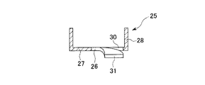
すなわち、本実施形態の環状部材25は、第1参考例と同様、円板部27と円筒部28とを有するアルミニウム製のものであるが、図4および図5に示すように、その円板部27の一部に、半径方向に沿って内端から円筒部28の方向に延在した後円板部27の円筒部28との境界近傍で円筒部28に沿って円弧状に延在する形状の切れ目30によって切断され、かつ軸線方向において円筒部28に対し反対側に突出ししかも先端側ほど突出量が大きくなるように斜めに折り曲げられた形状の傾斜部31を有している。
【0032】
そして、図示は略すが、このような環状部材25が複数、互いの傾斜部31同士が同一の螺旋状をなすように順次円周方向の位相をずらして配置されている。すなわち、空気流路14aにおいては、空気流路14aの軸線を中心とした同一の仮想の螺旋上に、すべての環状部材25の傾斜部31が配置されており、空気流路15aにおいても、空気流路15aの軸線を中心とした同一の仮想の螺旋上に、すべての環状部材25の傾斜部31が配置されている。
【0033】
以上に述べた本実施形態によれば、複数の環状部材25が、一部が切断されかつ斜めに折り曲げられた形状の傾斜部31をそれぞれ有し、それぞれの傾斜部31同士が螺旋状をなすように配置されているため、傾斜部31で案内される冷却用の空気が螺旋状に流れることになり、この空気による冷却効率をさらに向上させることができる。したがって、ワーク11および加工軸12の加工中の温度上昇をさらに十分に抑えることができる。
【0034】
次に、第2参考例の加工機用治具の冷却構造を図6を参照して以下に第1参考例との相違部分を中心に説明する。なお、第1参考例と同様の部分には同一の符号を付しその説明は略す。
【0035】
第2参考例は、冷却フィン部24が環状部材ではなく、加工軸12の上部連結部材15の空気流路15aを形成する内壁15bおよび加工軸12の加工軸本体14の空気流路14aを形成する内壁14bにそれぞれ形成されたネジ山34からなっている。
【0036】
このような第2参考例によれば、冷却フィン部24が、冷却流路14a,15aの内壁14b,15bに形成されたネジ山34からなるため、特に冷却流路14a,15aの流路断面積を大きくとれない場合であっても、容易に冷却フィン部24を形成することができる。
【0037】
次に、第3参考例の加工機用治具の冷却構造を図7および図8を参照して以下に第1参考例との相違部分を中心に説明する。なお、第1参考例と同様の部分には同一の符号を付しその説明は略す。
【0038】
第3参考例は、冷却フィン部24が環状部材ではなく、加工軸12の上部連結部材15の空気流路15aを形成する内壁15bおよび加工軸12の加工軸本体14の空気流路14aを形成する内壁14bにそれぞれ圧入されたハニカムコア37からなっている。ここで、このハニカムコア37は、空気流路14a,15aの軸線方向に直交する断面が六角形状をなすように、言い換えればハニカムの両端開口部を空気流路14a,15aの軸線方向における両側に配置する姿勢で空気流路14a,15aにそれぞれ圧入されている。
【0039】
このような第3参考例によれば、冷却フィン部24が、冷却流路14a,15aの内壁14b,15bにそれぞれ圧入されたハニカムコア37からなるため、容易に冷却フィン部24を形成することができる。
【0040】
なお、実施形態では、それぞれ加工軸12の上部連結部材15の空気流路15aを形成する内壁15bおよび加工軸12の加工軸本体14の空気流路14aを形成する内壁14bに同じ構造の冷却フィン部24を設ける場合を例にとり説明したが、これらを適宜組み合わせて異なる構造の冷却フィン部24を設けることも勿論可能である。また、加工軸12の上部連結部材15の空気流路15aを形成する内壁15bのみに冷却フィン部24を設けたり、加工軸12の加工軸本体14の空気流路14aを形成する内壁14bのみに冷却フィン部24を設けたりしても良い。
【0041】
【発明の効果】
以上詳述したように、本発明の請求項1記載の加工機用治具の冷却構造によれば、冷却流路を形成する内壁に、表面積を拡大させる冷却フィン部が設けられているため、流通する冷却用の空気による冷却効率を向上させることができる。したがって、加工中の温度上昇を十分に抑えることができる。
冷却フィン部が内壁に圧入される複数の環状部材からなるため、複数の環状部材を別途作製して圧入すれば良く、特に冷却流路の断面積を大きくとれる場合であって大きな冷却フィン部を形成する場合の製造が容易となる。
複数の環状部材が、一部が切断されかつ斜めに折り曲げられた形状の傾斜部をそれぞれ有し、それぞれの傾斜部同士が螺旋状をなすように配置されているため、傾斜部で案内される冷却用の空気が螺旋状に流れることになり、この空気による冷却効率をさらに向上させることができる。したがって、加工中の温度上昇をさらに十分に抑えることができる。
【0044】
本発明の請求項2記載の加工機用治具の冷却構造によれば、環状部材は熱伝導率の高いアルミニウムからなるため、流通する冷却用の空気による冷却効率をさらに向上させることができる。したがって、加工中の温度上昇をさらに十分に抑えることができる。
【図面の簡単な説明】
【図1】 第1参考例の加工機用治具の冷却構造を示す正断面図である。
【図2】 第1参考例の加工機用治具の冷却構造の環状部材を示す正断面図である。
【図3】 第1参考例の加工機用治具の冷却構造の環状部材を示す平面図である。
【図4】 本発明の一実施形態の加工機用治具の冷却構造の環状部材を示す正断面図である。
【図5】 本発明の一実施形態の加工機用治具の冷却構造の環状部材を示す平面図である。
【図6】 第2参考例の加工機用治具の冷却構造を示す正断面図である。
【図7】 第3参考例の加工機用治具の冷却構造を示す正断面図である。
【図8】 第3参考例の加工機用治具の冷却構造のハニカムコア等を示す平断面図である。
【符号の説明】
12 加工軸(加工機用治具)
14a,15a 冷却流路
14b,15b 内壁
24 冷却フィン部
25 環状部材
31 傾斜部 [0001]
BACKGROUND OF THE INVENTION
The present invention relates to a cooling structure for a jig for a processing machine in which a cooling flow path for circulating cooling air is formed.
[0002]
[Prior art]
For example, Japanese Patent Application Laid-Open No. 2001-47311 discloses a technique related to a cooling structure for a processing machine jig in which a cooling flow path for circulating cooling air is formed. In this publication, when a dry cutting method is employed in which cutting is performed without using cutting oil, the effect of thermal strain generated on the machining axis increases, so cooling inside the machining axis that supports the workpiece. A hobbing machine that suppresses thermal distortion and secures processing accuracy by forming a cooling channel through which air flows is described.
[0003]
[Problems to be solved by the invention]
However, when a dry cut method is employed in which cutting is performed without using cutting oil, it is sufficient even if a cooling flow path is formed inside the machining shaft and cooling air is circulated as in the above publication. In some cases, cooling was not possible. In particular, when stacking is performed in which a plurality of workpieces are stacked at once in order to improve the processing efficiency in spur gear cutting, the temperature of the workpiece and the jig that supports the workpiece during processing is naturally understood. Therefore, the cooling structure of the above publication cannot sufficiently suppress the temperature rise.
[0004]
Therefore, an object of the present invention is to provide a cooling structure for a jig for a processing machine that can sufficiently suppress a temperature rise during processing.
[0005]
[Means for Solving the Problems]
In order to achieve the above object, the cooling structure for a processing machine jig according to claim 1 of the present invention has cooling channels (for example,
[0006]
Thus, since the cooling fin part which expands a surface area is provided in the inner wall which forms a cooling flow path, the cooling efficiency by the cooling air which distribute | circulates can be improved.
In addition, since the cooling fin portion is composed of a plurality of annular members that are press-fitted into the inner wall, it is only necessary to separately produce and press-fit a plurality of annular members, particularly when the cooling channel has a large cross-sectional area and a large cooling fin. Manufacturing in the case of forming a part becomes easy.
Further, since the plurality of annular members each have an inclined portion that is partially cut and bent obliquely, and each inclined portion is arranged so as to form a spiral shape, it is guided by the inclined portion. The cooling air to be flowed spirally, and the cooling efficiency by this air can be further improved.
[0011]
The cooling structure for a processing machine jig according to claim 2 of the present invention is characterized in that the annular member is made of aluminum with respect to the cooling structure of claim 1.
[0012]
Thus, since the annular member is made of aluminum having a high thermal conductivity, the cooling efficiency by the circulating cooling air can be further improved.
[0017]
DETAILED DESCRIPTION OF THE INVENTION
The cooling structure for the processing machine jig of the first reference example will be described below with reference to FIGS.
[0018]
The jig for the processing machine of the first reference example is a dry cutting method that performs cutting without using cutting oil, and further, gear cutting is performed at a time in a state where workpieces are stacked in a plurality of stages in order to improve processing efficiency. For a gear cutting machine (hobbing machine) that performs stacking processing, specifically, as shown in FIG. 1, the inner peripheral side is fitted and centered in a state where a plurality of
[0019]
The
[0020]
The
[0021]
The
[0022]
A plurality of
[0023]
At this time, in order to prevent the temperature rise of the
[0024]
In the first reference example , the
[0025]
The
[0026]
There are a plurality of such
[0027]
According to the first reference example described above, the
[0028]
In addition, since the cooling
[0029]
Furthermore, since the
[0030]
Next, a cooling structure for a processing machine jig according to an embodiment of the present invention will be described with reference to FIGS. 4 and 5 focusing on differences from the first reference example . In addition, the same code | symbol is attached | subjected to the part similar to a 1st reference example, and the description is abbreviate | omitted .
[0031]
In the present embodiment, the shape of the
That is, the
[0032]
And although illustration is abbreviate | omitted, the phase of the circumferential direction is arrange | positioned sequentially so that there may be two or more such
[0033]
According to this embodiment described above, each of the plurality of
[0034]
Next, the cooling structure for the processing machine jig of the second reference example will be described below with reference to FIG. 6 focusing on the differences from the first reference example . In addition, the same code | symbol is attached | subjected to the part similar to a 1st reference example, and the description is abbreviate | omitted .
[0035]
In the second reference example , the cooling
[0036]
According to the second reference example as described above, the cooling
[0037]
Next, the cooling structure for the processing machine jig of the third reference example will be described below with reference to FIGS. 7 and 8 focusing on the differences from the first reference example . In addition, the same code | symbol is attached | subjected to the part similar to a 1st reference example, and the description is abbreviate | omitted .
[0038]
In the third reference example , the cooling
[0039]
According to the third reference example as described above, the cooling
[0040]
In the implementation form, the cooling of the same structure on the
[0041]
【The invention's effect】
As described above in detail, according to the cooling structure for a jig for a processing machine according to claim 1 of the present invention, the cooling fin portion that enlarges the surface area is provided on the inner wall that forms the cooling flow path. The cooling efficiency by the circulating cooling air can be improved. Therefore, the temperature rise during processing can be sufficiently suppressed.
Since the cooling fin portion is composed of a plurality of annular members that are press-fitted into the inner wall, a plurality of annular members may be separately prepared and press-fitted, especially when the cross-sectional area of the cooling flow path can be increased and a large cooling fin portion is provided. Manufacturing in the case of forming becomes easy.
Since the plurality of annular members each have an inclined portion that is partially cut and bent obliquely, and each of the inclined portions is arranged so as to form a spiral shape, the annular members are guided by the inclined portion. The cooling air flows spirally, and the cooling efficiency by this air can be further improved. Therefore, the temperature rise during processing can be more sufficiently suppressed.
[0044]
According to the cooling structure for a processing machine jig according to claim 2 of the present invention, since the annular member is made of aluminum having a high thermal conductivity, the cooling efficiency by the circulating cooling air can be further improved. Therefore, the temperature rise during processing can be more sufficiently suppressed.
[Brief description of the drawings]
FIG. 1 is a front sectional view showing a cooling structure of a jig for a processing machine according to a first reference example .
FIG. 2 is a front sectional view showing an annular member having a cooling structure for a processing machine jig according to a first reference example .
FIG. 3 is a plan view showing an annular member of a cooling structure for a processing machine jig of a first reference example .
4 is a front sectional view showing the annular member of the cooling structure of the machine jig of an embodiment of the present invention.
Is a plan view showing the annular member of the cooling structure of the machine jig of an embodiment of the present invention; FIG.
FIG. 6 is a front sectional view showing a cooling structure of a jig for a processing machine according to a second reference example .
FIG. 7 is a front sectional view showing a cooling structure of a processing machine jig of a third reference example .
FIG. 8 is a plan sectional view showing a honeycomb core or the like having a cooling structure for a jig for a processing machine according to a third reference example .
[Explanation of symbols]
12 Processing axis (Jig for processing machine)
14a, 15a
Claims (2)
前記冷却流路を形成する内壁には、表面積を拡大させる冷却フィン部が設けられており、
前記冷却フィン部は、前記内壁に圧入された複数の環状部材からなっていて、
前記環状部材は、一部が切断されかつ斜めに折り曲げられた形状の傾斜部を有しており、複数の前記環状部材が、互いの傾斜部同士が螺旋状をなすように配置されていることを特徴とする加工機用治具の冷却構造。In the cooling structure of the processing machine jig in which the cooling flow path for circulating the cooling air is formed inside,
The inner wall that forms the cooling flow path is provided with a cooling fin portion that enlarges the surface area ,
The cooling fin portion is composed of a plurality of annular members press-fitted into the inner wall,
The annular member has an inclined portion that is partially cut and bent obliquely, and the plurality of annular members are arranged so that the inclined portions are spiral. Cooling structure for jigs for processing machines.
Priority Applications (1)
| Application Number | Priority Date | Filing Date | Title |
|---|---|---|---|
| JP2001376339A JP3742002B2 (en) | 2001-12-10 | 2001-12-10 | Cooling structure for jigs for processing machines |
Applications Claiming Priority (1)
| Application Number | Priority Date | Filing Date | Title |
|---|---|---|---|
| JP2001376339A JP3742002B2 (en) | 2001-12-10 | 2001-12-10 | Cooling structure for jigs for processing machines |
Publications (2)
| Publication Number | Publication Date |
|---|---|
| JP2003175438A JP2003175438A (en) | 2003-06-24 |
| JP3742002B2 true JP3742002B2 (en) | 2006-02-01 |
Family
ID=19184555
Family Applications (1)
| Application Number | Title | Priority Date | Filing Date |
|---|---|---|---|
| JP2001376339A Expired - Fee Related JP3742002B2 (en) | 2001-12-10 | 2001-12-10 | Cooling structure for jigs for processing machines |
Country Status (1)
| Country | Link |
|---|---|
| JP (1) | JP3742002B2 (en) |
Cited By (2)
| Publication number | Priority date | Publication date | Assignee | Title |
|---|---|---|---|---|
| CN104646738A (en) * | 2015-02-02 | 2015-05-27 | 柳州市二和汽车零部件有限公司 | Method for processing car cooling fin |
| CN108145252A (en) * | 2017-12-20 | 2018-06-12 | 重庆顺淮机械制造有限公司 | Multifunction gear hobbing device |
Families Citing this family (2)
| Publication number | Priority date | Publication date | Assignee | Title |
|---|---|---|---|---|
| JP2015136758A (en) * | 2014-01-22 | 2015-07-30 | シバム オートテック リミテッド | Hobbing method of multiple gears and its application method |
| WO2022190176A1 (en) * | 2021-03-08 | 2022-09-15 | 株式会社Fuji | Workpiece clamping device |
-
2001
- 2001-12-10 JP JP2001376339A patent/JP3742002B2/en not_active Expired - Fee Related
Cited By (3)
| Publication number | Priority date | Publication date | Assignee | Title |
|---|---|---|---|---|
| CN104646738A (en) * | 2015-02-02 | 2015-05-27 | 柳州市二和汽车零部件有限公司 | Method for processing car cooling fin |
| CN108145252A (en) * | 2017-12-20 | 2018-06-12 | 重庆顺淮机械制造有限公司 | Multifunction gear hobbing device |
| CN108145252B (en) * | 2017-12-20 | 2019-02-15 | 重庆顺淮机械制造有限公司 | Multifunctional gear hobbing device |
Also Published As
| Publication number | Publication date |
|---|---|
| JP2003175438A (en) | 2003-06-24 |
Similar Documents
| Publication | Publication Date | Title |
|---|---|---|
| CA2970374C (en) | Rotating chuck with coolant groove arrangement | |
| JP6398767B2 (en) | Tool holder | |
| JP4945382B2 (en) | Groove cutting method and groove cutting apparatus | |
| US20120163931A1 (en) | Tool | |
| JP3742002B2 (en) | Cooling structure for jigs for processing machines | |
| EP4151364B1 (en) | Special-shaped wheel having positive correlation water passing structure for full-grinding surface | |
| JP2007092968A (en) | Nut manufacturing method | |
| US9902002B2 (en) | Reamers with radially extending flutes | |
| JP2022178742A (en) | Broach for turbine disc groove processing, and turbine disc groove processing method using the broach | |
| US20240060730A1 (en) | Heat sink composed of metal | |
| RU2571973C2 (en) | Production of tube for heat exchanger, for example, for vehicle | |
| JP2008232566A (en) | Method of forming connector part for heat exchanger | |
| JP2006187848A (en) | Core drill | |
| JP4484716B2 (en) | Drilling drill and method of machining torsion groove in drilling drill | |
| JP3252266U (en) | Cutter cooling collet | |
| KR100620733B1 (en) | Mold for generator coil to form cooling flow path | |
| JPH031097A (en) | Heat exchanger | |
| CN111872450A (en) | Cutter for machining taper hole | |
| JP5319928B2 (en) | Boring tool and drilling method | |
| JP2011212778A (en) | Cutting tool and method for cutting using same | |
| JP2007010296A (en) | Heat exchanger | |
| JP2006224206A (en) | Drilling tool | |
| WO2018124254A1 (en) | Metal plate burring method | |
| EP3593930B1 (en) | Machine reamer with cutting edges from progressive cutting materials | |
| JPH04260789A (en) | Manufacture of cylindrical heat exchanger |
Legal Events
| Date | Code | Title | Description |
|---|---|---|---|
| A977 | Report on retrieval |
Free format text: JAPANESE INTERMEDIATE CODE: A971007 Effective date: 20050307 |
|
| A131 | Notification of reasons for refusal |
Free format text: JAPANESE INTERMEDIATE CODE: A131 Effective date: 20050315 |
|
| A521 | Written amendment |
Free format text: JAPANESE INTERMEDIATE CODE: A523 Effective date: 20050511 |
|
| TRDD | Decision of grant or rejection written | ||
| A01 | Written decision to grant a patent or to grant a registration (utility model) |
Free format text: JAPANESE INTERMEDIATE CODE: A01 Effective date: 20051101 |
|
| A61 | First payment of annual fees (during grant procedure) |
Free format text: JAPANESE INTERMEDIATE CODE: A61 Effective date: 20051109 |
|
| R150 | Certificate of patent or registration of utility model |
Free format text: JAPANESE INTERMEDIATE CODE: R150 |
|
| FPAY | Renewal fee payment (event date is renewal date of database) |
Free format text: PAYMENT UNTIL: 20081118 Year of fee payment: 3 |
|
| FPAY | Renewal fee payment (event date is renewal date of database) |
Free format text: PAYMENT UNTIL: 20091118 Year of fee payment: 4 |
|
| FPAY | Renewal fee payment (event date is renewal date of database) |
Free format text: PAYMENT UNTIL: 20091118 Year of fee payment: 4 |
|
| FPAY | Renewal fee payment (event date is renewal date of database) |
Free format text: PAYMENT UNTIL: 20101118 Year of fee payment: 5 |
|
| FPAY | Renewal fee payment (event date is renewal date of database) |
Free format text: PAYMENT UNTIL: 20101118 Year of fee payment: 5 |
|
| FPAY | Renewal fee payment (event date is renewal date of database) |
Free format text: PAYMENT UNTIL: 20111118 Year of fee payment: 6 |
|
| FPAY | Renewal fee payment (event date is renewal date of database) |
Free format text: PAYMENT UNTIL: 20111118 Year of fee payment: 6 |
|
| FPAY | Renewal fee payment (event date is renewal date of database) |
Free format text: PAYMENT UNTIL: 20121118 Year of fee payment: 7 |
|
| FPAY | Renewal fee payment (event date is renewal date of database) |
Free format text: PAYMENT UNTIL: 20131118 Year of fee payment: 8 |
|
| LAPS | Cancellation because of no payment of annual fees |