EP4151361A1 - Magazine and machine tool - Google Patents
Magazine and machine tool Download PDFInfo
- Publication number
- EP4151361A1 EP4151361A1 EP20938662.2A EP20938662A EP4151361A1 EP 4151361 A1 EP4151361 A1 EP 4151361A1 EP 20938662 A EP20938662 A EP 20938662A EP 4151361 A1 EP4151361 A1 EP 4151361A1
- Authority
- EP
- European Patent Office
- Prior art keywords
- tool
- magazine
- predetermined position
- design
- display unit
- Prior art date
- Legal status (The legal status is an assumption and is not a legal conclusion. Google has not performed a legal analysis and makes no representation as to the accuracy of the status listed.)
- Granted
Links
Images






Classifications
-
- B—PERFORMING OPERATIONS; TRANSPORTING
- B23—MACHINE TOOLS; METAL-WORKING NOT OTHERWISE PROVIDED FOR
- B23Q—DETAILS, COMPONENTS, OR ACCESSORIES FOR MACHINE TOOLS, e.g. ARRANGEMENTS FOR COPYING OR CONTROLLING; MACHINE TOOLS IN GENERAL CHARACTERISED BY THE CONSTRUCTION OF PARTICULAR DETAILS OR COMPONENTS; COMBINATIONS OR ASSOCIATIONS OF METAL-WORKING MACHINES, NOT DIRECTED TO A PARTICULAR RESULT
- B23Q3/00—Devices holding, supporting, or positioning work or tools, of a kind normally removable from the machine
- B23Q3/155—Arrangements for automatic insertion or removal of tools, e.g. combined with manual handling
- B23Q3/1552—Arrangements for automatic insertion or removal of tools, e.g. combined with manual handling parts of devices for automatically inserting or removing tools
- B23Q3/15526—Storage devices; Drive mechanisms therefor
-
- B—PERFORMING OPERATIONS; TRANSPORTING
- B23—MACHINE TOOLS; METAL-WORKING NOT OTHERWISE PROVIDED FOR
- B23Q—DETAILS, COMPONENTS, OR ACCESSORIES FOR MACHINE TOOLS, e.g. ARRANGEMENTS FOR COPYING OR CONTROLLING; MACHINE TOOLS IN GENERAL CHARACTERISED BY THE CONSTRUCTION OF PARTICULAR DETAILS OR COMPONENTS; COMBINATIONS OR ASSOCIATIONS OF METAL-WORKING MACHINES, NOT DIRECTED TO A PARTICULAR RESULT
- B23Q11/00—Accessories fitted to machine tools for keeping tools or parts of the machine in good working condition or for cooling work; Safety devices specially combined with or arranged in, or specially adapted for use in connection with, machine tools
- B23Q11/08—Protective coverings for parts of machine tools; Splash guards
-
- B—PERFORMING OPERATIONS; TRANSPORTING
- B23—MACHINE TOOLS; METAL-WORKING NOT OTHERWISE PROVIDED FOR
- B23Q—DETAILS, COMPONENTS, OR ACCESSORIES FOR MACHINE TOOLS, e.g. ARRANGEMENTS FOR COPYING OR CONTROLLING; MACHINE TOOLS IN GENERAL CHARACTERISED BY THE CONSTRUCTION OF PARTICULAR DETAILS OR COMPONENTS; COMBINATIONS OR ASSOCIATIONS OF METAL-WORKING MACHINES, NOT DIRECTED TO A PARTICULAR RESULT
- B23Q3/00—Devices holding, supporting, or positioning work or tools, of a kind normally removable from the machine
- B23Q3/155—Arrangements for automatic insertion or removal of tools, e.g. combined with manual handling
- B23Q3/1552—Arrangements for automatic insertion or removal of tools, e.g. combined with manual handling parts of devices for automatically inserting or removing tools
- B23Q3/15526—Storage devices; Drive mechanisms therefor
- B23Q3/15533—Storage devices; Drive mechanisms therefor combined with manual tool transfers
-
- B—PERFORMING OPERATIONS; TRANSPORTING
- B23—MACHINE TOOLS; METAL-WORKING NOT OTHERWISE PROVIDED FOR
- B23Q—DETAILS, COMPONENTS, OR ACCESSORIES FOR MACHINE TOOLS, e.g. ARRANGEMENTS FOR COPYING OR CONTROLLING; MACHINE TOOLS IN GENERAL CHARACTERISED BY THE CONSTRUCTION OF PARTICULAR DETAILS OR COMPONENTS; COMBINATIONS OR ASSOCIATIONS OF METAL-WORKING MACHINES, NOT DIRECTED TO A PARTICULAR RESULT
- B23Q3/00—Devices holding, supporting, or positioning work or tools, of a kind normally removable from the machine
- B23Q3/155—Arrangements for automatic insertion or removal of tools, e.g. combined with manual handling
- B23Q3/1552—Arrangements for automatic insertion or removal of tools, e.g. combined with manual handling parts of devices for automatically inserting or removing tools
- B23Q3/1554—Transfer mechanisms, e.g. tool gripping arms; Drive mechanisms therefore
-
- B—PERFORMING OPERATIONS; TRANSPORTING
- B23—MACHINE TOOLS; METAL-WORKING NOT OTHERWISE PROVIDED FOR
- B23Q—DETAILS, COMPONENTS, OR ACCESSORIES FOR MACHINE TOOLS, e.g. ARRANGEMENTS FOR COPYING OR CONTROLLING; MACHINE TOOLS IN GENERAL CHARACTERISED BY THE CONSTRUCTION OF PARTICULAR DETAILS OR COMPONENTS; COMBINATIONS OR ASSOCIATIONS OF METAL-WORKING MACHINES, NOT DIRECTED TO A PARTICULAR RESULT
- B23Q3/00—Devices holding, supporting, or positioning work or tools, of a kind normally removable from the machine
- B23Q3/155—Arrangements for automatic insertion or removal of tools, e.g. combined with manual handling
- B23Q3/1552—Arrangements for automatic insertion or removal of tools, e.g. combined with manual handling parts of devices for automatically inserting or removing tools
- B23Q3/15526—Storage devices; Drive mechanisms therefor
- B23Q2003/15532—Storage devices; Drive mechanisms therefor the storage device including tool pots, adaptors or the like
-
- B—PERFORMING OPERATIONS; TRANSPORTING
- B23—MACHINE TOOLS; METAL-WORKING NOT OTHERWISE PROVIDED FOR
- B23Q—DETAILS, COMPONENTS, OR ACCESSORIES FOR MACHINE TOOLS, e.g. ARRANGEMENTS FOR COPYING OR CONTROLLING; MACHINE TOOLS IN GENERAL CHARACTERISED BY THE CONSTRUCTION OF PARTICULAR DETAILS OR COMPONENTS; COMBINATIONS OR ASSOCIATIONS OF METAL-WORKING MACHINES, NOT DIRECTED TO A PARTICULAR RESULT
- B23Q3/00—Devices holding, supporting, or positioning work or tools, of a kind normally removable from the machine
- B23Q3/155—Arrangements for automatic insertion or removal of tools, e.g. combined with manual handling
- B23Q3/157—Arrangements for automatic insertion or removal of tools, e.g. combined with manual handling of rotary tools
-
- Y—GENERAL TAGGING OF NEW TECHNOLOGICAL DEVELOPMENTS; GENERAL TAGGING OF CROSS-SECTIONAL TECHNOLOGIES SPANNING OVER SEVERAL SECTIONS OF THE IPC; TECHNICAL SUBJECTS COVERED BY FORMER USPC CROSS-REFERENCE ART COLLECTIONS [XRACs] AND DIGESTS
- Y10—TECHNICAL SUBJECTS COVERED BY FORMER USPC
- Y10T—TECHNICAL SUBJECTS COVERED BY FORMER US CLASSIFICATION
- Y10T483/00—Tool changing
- Y10T483/11—Tool changing with safety means
- Y10T483/115—Guard
-
- Y—GENERAL TAGGING OF NEW TECHNOLOGICAL DEVELOPMENTS; GENERAL TAGGING OF CROSS-SECTIONAL TECHNOLOGIES SPANNING OVER SEVERAL SECTIONS OF THE IPC; TECHNICAL SUBJECTS COVERED BY FORMER USPC CROSS-REFERENCE ART COLLECTIONS [XRACs] AND DIGESTS
- Y10—TECHNICAL SUBJECTS COVERED BY FORMER USPC
- Y10T—TECHNICAL SUBJECTS COVERED BY FORMER US CLASSIFICATION
- Y10T483/00—Tool changing
- Y10T483/13—Tool changing with control means energized in response to activator stimulated by condition sensor
- Y10T483/136—Responsive to tool
Definitions
- the present invention relates to a magazine and a machine tool.
- Japanese Patent Application Laying-Open No. 2019-42878 discloses a tool magazine comprising a first conveyer unit and a second conveyer unit that hold a plurality of tools such as drills, end mills, milling cutters, etc. detachably and convey the tools along an endless path, and a cover body that accommodates the first and second conveyer units.
- the cover body is provided with a first opening and a second opening for manually attaching and detaching a tool to and from the first conveyer unit and the second conveyer unit, respectively.
- a magazine according to the present invention comprises: a conveyer unit that has a plurality of tool holders that each hold a tool detachably and conveys the plurality of tool holders; and a cover body that accommodates the conveyer unit.
- the conveyer unit allows a tool to be manually attached to and detached from a tool holder conveyed to a predetermined position.
- the magazine further comprises a display unit that is provided inside the cover body and displays a first design.
- the first design represents an arc or circumference for a diameter corresponding to a maximum diameter of a tool which can be held by the tool holder.
- the operator when an operator manually attaches a tool to a tool holder, the operator can intuitively recognize a maximum diameter of a tool which can be held by the tool holder by confirming an arc or circumference represented by the first design that the display unit displays. A manual tool attachment/detachment operation can thus be performed easily and appropriately.
- the tool holder conveyed to the predetermined position receives or has a tool removed therefrom along a predetermined center axis.
- the display unit has a display surface that is composed of a plane orthogonal to an axial direction of the predetermined center axis and displays the first design.
- the operator when the operator performs an operation to attach/detach a tool at a position opposite to a tool holder in the axial direction of the predetermined center axis, the operator more easily confirms the arc or circumference represented by the first design displayed on the display surface.
- the display unit is provided sideways of the predetermined position.
- the arc or circumference has a center point aligned in level to the predetermined center axis.
- the operator when the operator manually attaches a tool to a tool holder, the operator can easily compare the tool in size with the arc or circumference represented by the first design that the display unit displays.
- the display unit further displays a maximum diameter of a tool which can be held by the tool holder.
- the operator can accurately recognize the maximum diameter of the tool that can be held by the tool holder.
- the cover body is provided with an opening that allows a tool to be manually attached/detached to/from the tool holder conveyed to the predetermined position.
- the display unit has at least a portion opposite to an opening plane defined by the opening in the cover body.
- the operator can easily confirm through the opening plane defined by the opening in the cover body the arc or circumference represented by the first design that the display unit displays.
- the display unit further displays first information in a variable display form about a tool held by a tool holder and/or the conveyer unit.
- the operator when the operator manually attaches/detaches a tool to/from a tool holder, the operator can recognize the first information about the tool held by the tool holder and/or the conveyer unit by confirming a display form at the display unit.
- the manual tool attachment/detachment operation can be performed more easily and appropriately.
- the first information includes at least one of: whether a tool is present or absent in a tool holder conveyed to the predetermined position; how a tool is clamped in the tool holder conveyed to the predetermined position; and in what state the conveyer unit is operated to convey the tool holder.
- the operator can recognize the first information by confirming the display form at the display unit.
- the display unit includes a plate material including a light transmitting portion, and a light emitting device that emits light from a back side of the plate material toward the light transmitting portion in a plurality of light emitting modes.
- variable display form at the display unit can be implemented according to the light emitting modes of the light emitting device confirmed in the light transmitting portion.
- the plurality of light emitting modes include a light emitting mode in a specific light emitting state selected from turning on light, turning off light, and flashing.
- the plurality of light emitting modes include a light emitting mode of a specific light emitting color selected from a plurality of colors.
- variable display form at the display unit can be implemented according to these light emitting state and/or light emitting color confirmed in the light transmitting portion.
- the plate material further displays second information including at least one of: an indicator indicating the predetermined position; a specification of a shank of a tool held by a tool holder; and an orientation of the tool held by the tool holder that is about an axis of rotation of the tool.
- the operator when the operator manually attaches/detaches a tool to/from a tool holder the operator can recognize the second information by confirming the plate material.
- the manual tool attachment/detachment operation can be performed more easily and appropriately.
- At least one of: an indicator indicating the predetermined position; a specification of a shank of a tool held by a tool holder; and an orientation of the tool held by the tool holder that is about an axis of rotation of the tool is represented by a second design.
- the light transmitting portion corresponds to the second design.
- the operator can easily recognize the second information that is represented by the second design as the light emitting device emits light toward the light transmitting portion.
- a machine tool according to the present invention comprises any magazine as described above.
- the thus configured machine tool can be implemented to allow a manual tool attachment/detachment operation to be easily and appropriately performed in the magazine.
- the present invention can thus provide a magazine that allows a manual tool attachment/detachment operation to be easily and appropriately performed, and a machine tool comprising such a magazine.
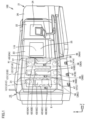
- Fig. 1 is a perspective view of a machine tool comprising a magazine according to a first embodiment of the present invention.
- a machine tool 100 is a numerically control (NC) machine tool in which a variety of types of operations for processing a workpiece are automated through numerical control by a computer.
- Machine tool 100 is a composite processing machine having a turning function using a fixed tool and a milling function using a rotating tool.
- an axis parallel to a rightward/leftward direction (or widthwise direction) of machine tool 100 and extending in a horizontal direction is referred to as a "Z axis”
- an axis parallel to a frontward/rearward direction (or depthwise direction) of machine tool 100 and extending in a horizontal direction is referred to as a "Y axis”
- an axis extending in a vertical direction is referred to as an "X axis.”
- a rightward direction is referred to as a "+ Z-axis direction” and a leftward direction is referred to as a "-Z-axis direction.”
- Fig. 1 a rightward direction is referred to as a "+ Z-axis direction”
- a leftward direction is referred to as a "-Z-axis direction.”
- a frontward direction with respect to the sheet of the figure is referred to as a "+ Y-axis direction” and a rearward direction with respect thereto is referred to as a "- Y-axis direction.”
- a downward direction is referred to as a "- X-axis direction.”
- the X-axis, the Y-axis, and the Z-axis are three axes orthogonal to one another.
- Machine tool 100 generally has a structure, as will be briefly described below.
- Machine tool 100 comprises a workpiece spindle and an opposite workpiece spindle for rotating a workpiece, a tool spindle for rotating a tool, a tool rest on which a plurality of tools are attached, a magazine 10 for accommodating a plurality of tools, and an automatic tool exchanger (ATC) for exchanging tools between magazine 10 and the tool spindle.
- ATC automatic tool exchanger
- Machine tool 100 further comprises a cover body 21.
- Cover body 21 defines a processing area 110 and configures an external appearance of machine tool 100.
- Processing area 110 is a space in which a workpiece is processed and which is generally sealed so as to prevent foreign matters such as chips or cutting oil from leaking outside processing area 110 as the workpiece is processed.
- Cover body 21 includes a first door 22, a second door 23, a side cover 26, and a magazine cover 41.
- Cover body 21 is provided with an opening that opens processing area 110 in the + Y-axis direction (or a frontward direction with respect to the machine) and the + X-axis direction (or an upward direction).
- First door 22 and second door 23 are disposed in the opening provided in cover body 21.
- Side cover 26 and magazine cover 41 are provided on sides, respectively, opposite in the Z-axis direction to the opening provided in cover body 21.
- First door 22 and second door 23 are slidable in the Z-axis direction between a closed position in which the opening provided in cover body 21 is closed and an open position in which the opening provided in cover body 21 is opened.
- First door 22 and second door 23 define processing area 110 when the doors are slid to the closed position.
- First door 22 and second door 23 are provided with a transparent window 24 and a transparent window 25, respectively. When first door 22 and second door 23 are slid to the open position, first door 22 and second door 23 overlap with side cover 26 in the Y-axis direction.
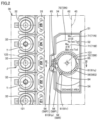
- FIG. 2 is a front view of the magazine of a portion surrounded by a two-dot chain line II indicated in Fig. 1 .
- Fig. 2 shows an inside of magazine cover 41.
- magazine 10 is provided outside processing area 110. Magazine 10 is provided on a side opposite in the Z-axis direction to side cover 26 with first door 22 and second door 23 interposed. Magazine 10 accommodates a plurality of tools such as a drill, an end mill, a milling cutter, etc. to be attached to the tool spindle. In the present embodiment, magazine 10 accommodates tools having a shank with a specification according to the HSK.
- Magazine 10 comprises a magazine base 31, a conveyer unit 36, and magazine cover 41 described above (or the cover body).
- Magazine base 31 is provided as a base member of magazine 10. Conveyer unit 36 is supported by magazine base 31. Magazine cover 41 is attached to magazine base 31. Magazine cover 41 forms a space with magazine base 31 for accommodating conveyer unit 36. Magazine cover 41 forms an external appearance of magazine 10 in a front view of magazine 10.
- Conveyer unit 36 includes a plurality of tool pots 32 (or tool holders). Tool pot 32 is configured to hold a tool detachably. Conveyer unit 36 is configured to convey the plurality of tool pots 32 along an endless path 121.
- Conveyer unit 36 further includes a conveying chain 33, a driving sprocket 37, a driven sprocket 38, and a motor (not shown).
- Driving sprocket 37 and driven sprocket 38 are spaced from each other. Driving sprocket 37 and driven sprocket 38 are spaced from each other in the X-axis direction (or a vertical direction). An output shaft of the motor is connected to driving sprocket 37 via a speed reducer. Conveying chain 33 is disposed annularly along path 121. Conveying chain 33 engages with and extends between driving sprocket 37 and driven sprocket 38.
- the plurality of tool pots 32 are coupled with one another via conveying chain 33.
- the plurality of tool pots 32 are disposed along path 121 at equal pitches.
- the plurality of tool pots 32 are disposed to be radially outer than annularly disposed conveying chain 33.
- Conveying chain 33 is circumferentially assigned consecutive numbers and provided with number tags each indicating the number of a tool pot 32.
- Tool pot 32 is in the form of a cylinder that can receive a tool and has a center axis 122 parallel to the Y-axis direction as a center. Path 121 extends between tool pots 32 across center axis 122 of each tool pot 32. Tool pot 32 has a clamping mechanism unit incorporated therein for clamping a tool by spring force or the like.
- Driving sprocket 37 rotates as rotation from the motor is transmitted to driving sprocket 37.
- conveying chain 33 moves in the circumferential direction and the plurality of tool pots 32 are conveyed along path 121.
- Magazine 10 comprises a plurality of conveyer units 36 (36A, 36B, 36C).
- Conveyer unit 36A is configured to convey a plurality of tool pots 32 along an endless path 121A.
- Conveyer unit 36B is configured to convey a plurality of tool pots 32 along an endless path 121B.
- Conveyer unit 36C is configured to convey a plurality of tool pots 32 along an endless path 121C.
- Conveyer units 36A, 36B, and 36C are provided independently of one another. Conveyer units 36A, 36B, and 36C are aligned in a horizontal direction (or the Z-axis direction). Conveyer units 36A, 36B, and 36C are provided such that paths 121A, 121B, and 121C are located in the same plane (i.e., the X-Z plane).
- Path 121 has a vertically elongate shape in which the X-axis direction (or a vertical direction) is a longitudinal direction and the Z-axis direction (or a horizontal direction) is a lateral direction. Path 121 is in the form of a track. Paths 121A, 121B, and 121C have the same shape. Paths 121A, 121B, and 121C may have different shapes.
- conveyer units 36A, 36B, and 36C accommodate tool groups used for processing different workpieces.
- a topmost portion of path 121 corresponds to a tool invoking position at which a tool fed from conveyer unit 36 to processing area 110 is positioned.
- the tool fed from conveyer unit 36 to processing area 110 moves from the current position of the tool to the tool invoking position as tool pot 32 is conveyed.
- tool pot 32 is conveyed in one direction selected from a forward direction along path 121 or the opposite direction along path 121 so that the tool moves a short distance from the current position to the tool invoking position.
- the tool positioned at the tool invoking position is transported toward processing area 110 by an automatic tool exchanger (not shown).
- Magazine 10 may have a plurality of conveyer units 36 other than three conveyer units 36 or may have a single conveyer unit 36. Further, for a machine tool comprising a tool rest provided with an ATC function, the magazine may accommodate a plurality of tools attached to the tool rest.
- Conveyer unit 36 is configured so that a tool can be manually attached/detached to/from tool pot 32 conveyed to a predetermined position J.
- Conveyer unit 36 shown in Fig. 2 has tool pot 32 No. 23 positioned at predetermined position J.
- center axis 122 or a predetermined center axis
- a tool is inserted into or removed from tool pot 32 conveyed to predetermined position J.
- the center axis of the shank of the tool matches center axis 122 of tool pot 32.
- Magazine cover 41 is provided with an opening 42 for manually attaching/detaching a tool to/from tool pot 32 conveyed to predetermined position J.
- Opening 42 allows a space for accommodating conveyer unit 36 and a space external thereto to be in communication with each other.
- Opening 42 is open in the + Y axis direction (or the frontward direction with respect to the machine). Opening 42 is open opposite to tool pot 32 conveyed to predetermined position J.
- Predetermined position J corresponds to a linear portion of path 121 in the form of a track. Predetermined position J is positioned below the tool invoking position. Predetermined position J is not particularly limited as long as it is at a level at which the operator's hand can easily reach predetermined position J.
- Magazine cover 41 includes a magazine door 43. Magazine door 43 is disposed in opening 42. Magazine door 43 is provided to be openable and closable between a closed position in which opening 42 is closed and an open position in which opening 42 is opened. Magazine door 43 may be opened/closed in any manner, and may for example be slid in a vertical direction or pivot about a vertically extending axis. Magazine door 43 may be composed of a transparent member.
- Magazine 10 further comprises a first operation unit 46 and a second operation unit 47.
- First operation unit 46 is operated when the operator indicates an operation of conveyer unit 36.
- First operation unit 46 is provided on magazine cover 41.
- First operation unit 46 is provided at a position adjacent to opening 42.
- First operation unit 46 is aligned with opening 42 in the Z-axis direction.
- First operation unit 46 may include an operating section for switching the conveyance of tool pot 32 in the conveyance unit 36 from an automatic mode (a mode according to a program executed by machine tool 100) to a manual mode.
- First operation unit 46 in the manual mode may include an operating section for identifying the number of tool pot 32 conveyed to predetermined position J.
- First operation unit 46 in the manual mode may include an operating section for starting the conveyance of tool pot 32.
- First operation unit 46 may for example be a touch panel or a push button.
- Second operation unit 47 is operated when the operator causes a clamping mechanism unit to perform an unclamping operation for tool pot 32 conveyed to predetermined position J.
- Second operation unit 47 is a foot switch.
- First operation unit 46 may be configured to include an operating section for causing the clamping mechanism unit to perform the unclamping operation. There may be no operation unit operated when the clamping mechanism unit is caused to perform the unclamping operation, and instead the operator may use a jig or the like to pull out a tool from tool pot 32.
- Magazine cover 41 is provided with a plurality of openings 42 (42A, 42B, 42C). Openings 42A, 42B, and 42C are provided for manual attachment and detachment of tools to and from conveyer units 36A, 36B, and 36C, respectively. Magazine cover 41 includes a plurality of magazine doors 43 (43A, 43B, and 43C). Magazine doors 43A, 43B, and 43C are disposed in openings 42A, 42B, and 42C, respectively.
- Magazine 10 comprises a plurality of first operation units 46 (46A, 46B, 46C) and a plurality of second operation units 47 (47A, 47B, 47C).
- First operation units 46A, 46B and 46C are operated when the operator indicates operations of conveyer units 36A, 36B and 36C, respectively.
- Second operation units 47A, 47B and 47C are operated when the operator causes the clamping mechanism unit to perform the unclamping operation in conveyer units 36A, 36B, and 36C, respectively.
- Fig. 3 is a cross section of the magazine taken along and seen in a direction indicated by an arrow of a line III-III indicated in Fig. 2 .
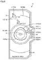
- Fig. 4 is a front view of a display unit shown in Fig. 2 . Referring to Figs. 2 to 4 , magazine 10 further comprises a display unit 51.
- Display unit 51 has a display surface 54.
- Display surface 54 is in the form of a plane.
- Display surface 54 displays characters 71, a first design 72, etc. described hereinafter.
- Display unit 51 is provided inside magazine cover 41. Display unit 51 is provided sideways of predetermined position J. Display unit 51 is provided adjacent to predetermined position J. Display unit 51 is provided adjacent to predetermined position J in the Z-axis direction. Display unit 51 is disposed inside the ring formed of the plurality of tool pots 32. A number tag indicating the number of tool pot 32 positioned at predetermined position J is disposed between display unit 51 and tool pot 32 positioned at predetermined position J. When magazine 10 is seen in a front view, tool pot 32 positioned at predetermined position J is located between display unit 51 and first operation unit 46 shown in Fig. 1 .
- Display surface 54 is composed of a plane orthogonal to center axis 122 of tool pot 32 positioned at predetermined position J.
- Display surface 54 may be composed of a plane inclined with respect to center axis 122 of tool pot 32 positioned at predetermined position J.
- Magazine 10 further comprises a decorative panel 34.
- Decorative panel 34 is in the form of a plate parallel to the X-Z plane.
- Decorative panel 34 is disposed inside the ring formed of the plurality of tool pots 32.
- Display unit 51 is attached to decorative panel 34.
- Display unit 51 has at least a portion opposite to an opening plane defined by opening 42 in magazine cover 41.
- display unit 51 (or display surface 54) has a portion opposite to the opening plane defined by opening 42 in magazine cover 41.
- the portion of display surface 54 opposite to the opening plane defined by opening 42 is larger in area than the remaining portion of display surface 54 that is not opposite to the opening plane defined by opening 42 (or is opposite to magazine cover 41).
- Display unit 51 may be disposed outside the ring formed of the plurality of tool pots 32.
- Display surface 54 may entirely be opposite to the opening plane defined by opening 42.
- the portion of display surface 54 opposite to the opening plane defined by opening 42 may have an area equal to or smaller than that of the remaining portion of display surface 54 that is not opposite to the opening plane defined by opening 42.
- Display unit 51 may be provided such that display surface 54 and the opening plane defined by opening 42 in magazine cover 41 are orthogonal to each other.
- Display unit 51 (or display surface 54) displays characters 71 (71N, 71W) and first design 72 (72N, 72W).
- Characters 71 indicate a maximum diameter of a tool which can be held by tool pot 32.
- characters 71N indicate a maximum diameter of a tool which can be held by tool pot 32 positioned at predetermined position J when no tool is attached to tool pot 32 adjacent to tool pot 32 positioned at predetermined position J.
- Characters 71W indicate a maximum diameter of a tool which can be held by tool pot 32 positioned at predetermined position J when a tool is attached to tool pot 32 adjacent to tool pot 32 positioned at predetermined position J.
- tool pot 32 No. 23 can hold a tool having a diameter of 130 mm.
- tool pot 32 No. 23 can hold a tool having a diameter of 70 mm.
- First design 72 represents an arc or circumference for a diameter corresponding to a maximum diameter of a tool which can be held by tool pot 32.
- the diameter for the arc or circumference represented by first design 72 is the same as the maximum diameter of the tool that can be held by tool pot 32.
- First design 72N is an arc for a diameter (130 mm) corresponding to a maximum diameter of a tool which can be held by tool pot 32 positioned at predetermined position J when no tool is attached to tool pot 32 adjacent to tool pot 32 positioned at predetermined position J.
- First design 72N is an arc about a center point 131.
- First design 72N is composed of two arcs divided in the X-axis direction (or the vertical direction). The two arcs are divided at a location at which predetermined position J and display unit 51 are opposite to each other.
- First design 72W is a circumference for a diameter (70 mm) corresponding to a maximum diameter of a tool which can be held by tool pot 32 positioned at predetermined position J when a tool is attached to tool pot 32 adjacent to tool pot 32 positioned at predetermined position J.
- First design 72W is a circumference about center point 131.
- center point 131 for the arc or circumference represented by first design 72 is aligned in level with center axis 122 of tool pot 32 positioned at predetermined position J.
- the level of center point 131 and center axis 122 is a level when a common horizontal plane is set as a reference, and it is for example a level when a surface of a floor on which machine tool 100 (or magazine 10) is installed is used as a reference.
- Center point 131 for the arc or circumference represented by first design 72 is located on a straight line that is an extension in the Z-axis direction of center axis 122 of tool pot 32 positioned at predetermined position J.
- Characters 71N overlap with first design 72N or are disposed in the vicinity of first design 72N. Characters 71W overlap with first design 72W or are disposed in the vicinity of first design 72W.
- center point 131 for the arc or circumference represented by first design 72 may be located on a straight line that is an extension in the X-axis direction (or the vertical direction) of center axis 122 of tool pot 32 positioned at predetermined position J.
- First design 72N may be a circumference about center point 131.
- First design 72W may be an arc about center point 131.
- Display unit 51 may display only one of first designs 72N and 72W.
- the operator when the operator manually attaches a tool to tool pot 32, the operator can intuitively recognize a maximum diameter of a tool which can be held by tool pot 32 by confirming the arc or circumference represented by first design 72 that display unit 51 displays. Further, the operator can accurately recognize the maximum diameter of the tool that can be held by tool pot 32 by confirming characters 71 that display unit 51 displays. Thus, the operator can easily and appropriately perform the manual tool attachment/detachment operation.
- display surface 54 is composed of a plane orthogonal to center axis 122 of tool pot 32 positioned at predetermined position J.
- center point 131 for an arc or circumference represented by first design 72 is aligned in level with center axis 122 of tool pot 32 positioned at predetermined position J.
- display unit 51 has at least a portion opposite to an opening plane defined by opening 42 in magazine cover 41.
- opening plane defined by opening 42 in magazine cover 41 the operator more easily confirms characters 71 and first design 72 displayed on display surface 54.
- a maximum diameter of a tool which can be held by tool pot 32 is a maximum value allowed as the diameter of the tool held by tool pot 32.
- a maximum diameter of a tool which can be held by tool pot 32 is a diameter of the tool when the center axis of the shank of the tool is set as a center.
- Display unit 51 includes a plate material 52.
- Plate material 52 is a flat plate orthogonal to center axis 122 of tool pot 32.
- Plate material 52 is an elongate plate having a length in a direction in which the plurality of tool pots 32 are aligned at predetermined position J (i.e., the X-axis direction), and a width in a direction orthogonal to the direction in which the plurality of tool pots 32 are aligned at predetermined position J and to center axis 122 of tool pot 32 (i.e., the Z-axis direction).
- plate material 52 has display surface 54.
- Plate material 52 has light transmitting portions 56 (56P, 56Q, 56R).
- Light transmitting portion 56 is composed of a member capable of transmitting light (or a transparent member).
- Display unit 51 further includes a light emitting device 53.
- Light emitting device 53 is, for example, a backlight including a light source such as an LED. Light emitting device 53 overlaps with plate material 52 in the Y-axis direction. Light emitting device 53 is disposed behind plate material 52 in the front view of magazine 10. Light emitting device 53 emits light behind plate material 52 toward light transmitting portion 56.
- Display unit 51 displays first information in a variable display form about a tool held by tool pot 32 and/or conveyer unit 36.
- the first information includes at least one of: whether a tool is present or absent in tool pot 32 conveyed to predetermined position J; how a tool is clamped in the tool pot conveyed to predetermined position J; and in what state conveyer unit 36 is operated to convey the tool pot.
- Light emitting device 53 emits light toward light transmitting portion 56 in a plurality of light emitting modes.
- the plurality of light emitting modes in light emitting device 53 may include a light emitting mode in a specific light emitting state selected from turning on light, turning off light, and flashing.
- the plurality of light emitting modes in light emitting device 53 may include a light emitting mode of a specific light emitting color selected from a plurality of colors.
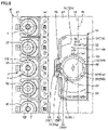
- Figs. 5 to 8 are front views indicating a light emitting mode in the light emitting device.
- first operation unit 46 to identify the number of tool pot 32 to be invoked to predetermined position J, which is currently No. 27, and start conveying tool pot 32. While tool pot 32 is conveyed, light transmitting portion 56P flashes in blue (In Fig. 5 , flashing in blue is represented by hatching and a ripply pattern).
- tool pot 32 No. 27 arrives at predetermined position J, and conveying tool pot 32 stops. Since a tool T is attached to tool pot 32 No. 27, light transmitting portion 56P turns on in blue (in Fig. 6 , hatching indicates that the light transmitting portion turns on in blue).
- the operator operates second operation unit 47 to cause the clamping mechanism unit of tool pot 32 No. 27 to perform the unclamping operation, and thus pulls the tool out of tool pot 32.
- light transmitting portions 56P, 56Q, and 56R turn on in blue (in Fig. 7 , hatching indicates that the light transmitting portions turn on in blue).
- Fig. 8 the operator attaches a new tool to tool pot 32 No. 27. In doing so, when the tool attached to tool pot 32 is not normally clamped, light transmitting portions 56P, 56Q and 56R flash in red (In Fig. 8 , flashing in red is represented by hatching and a ripply pattern).
- a light emitting mode in which light transmitting portions 56P, 56Q and 56R are turned off indicates that conveyer unit 36 is in the automatic mode.
- a light emitting mode in which light transmitting portion 56P flashes in blue indicates that tool pot 32 is being conveyed in the manual mode of conveyer unit 36.
- a mode in which light transmitting portions 56P, 56Q, and 56R turn on in blue indicates that no tool is attached to tool pot 32 positioned at predetermined position J in the manual mode of conveyer unit 36.
- a mode in which light transmitting portion 56P turns on in blue indicates that a tool is attached to tool pot 32 positioned at predetermined position J in the manual mode of conveyer unit 36.
- a light emitting mode in which light transmitting portions 56P, 56Q, and 56R flash in red indicates that a tool in tool pot 32 positioned at predetermined position J is not normally clamped.
- the operator when the operator manually attaches/detaches a tool to/from tool pot 32 the operator can confirm a light emitting mode in light transmitting portion 56 to recognize a mode of operation of conveyer unit 36, how tool pot 32 is conveyed by conveyer unit 36, whether a tool is present or absent in tool pot 32 positioned at predetermined position J, and how a tool in tool pot 32 positioned at predetermined position J is clamped.
- the operator can further easily and appropriately perform the manual tool attachment/detachment operation.
- a plurality of pieces of the first information may be indicated by providing a difference to an interval in time of flashing light transmitting portion 56.
- the variable display form of display unit 51 is not limited to the plurality of light emitting modes of light emitting device 53 and may be implemented e.g., by a display panel such as a liquid crystal panel.
- plate material 52 further displays second information including at least one of: an indicator indicating predetermined position J; a specification of a shank of a tool held in tool pot 32; and an orientation of the tool held in tool pot 32 that is about an axis of rotation of the tool.
- At least one of: the indicator indicating predetermined position J; the specification of the shank of the tool held by tool pot 32; and the orientation of the tool held by tool pot 32 that is about the axis of rotation of the tool is represented by a second design 61 (61p, 61q, 61r).
- Light transmitting portions 56 (56P, 56Q, 56R) correspond to second design 61 (61p, 61q, 61r), respectively.
- Plate material 52 further displays second design 61 (61p, 61q, 61r).
- Second design 61p is composed of an indicator indicating predetermined position J. Second design 61p is disposed between center axis 122 of tool pot 32 positioned at predetermined position J and center point 131. Second design 61p is disposed between center axis 122 of tool pot 32 positioned at predetermined position J and second design 61q. Second design 61p is composed of a plurality of geometrical figures aligned in the Z-axis direction, each having a predetermined width in a radial direction with respect to center point 131 and extending in the form of a strip in a direction along a circumference about center point 131.
- Second design 61q indicates a specification of a shank of a tool held by tool pot 32.
- Second design 61q is composed of a geometrical figure schematically representing a shape of a shank according to the HSK.
- Second design 61q is in the form of a ring about center point 131.
- a pair of recesses 65 recessed from an outer circumference of the ring radially inwards toward center point 131 and representing a drive key.
- a V-shaped groove 64 recessed in the form of the letter V from the outer circumference of the ring radially inwards toward center point 131.
- Second designs 61q and 61r represent an orientation of a tool held by tool pot 32 positioned at predetermined position J, that is about the axis of rotation of the tool.
- Second design 61r is disposed at the same phase position as V-shaped groove 64 in a circumferential direction with respect to center point 131.
- Second design 61r is disposed to be radially outer than V-shaped groove 64 with respect to center point 131.
- Second design 61r is a geometrical figure of an arrow indicating V-shaped groove 64.
- Light transmitting portion 56P corresponds to second design 61p composed of an indicator indicating predetermined position J.
- Light transmitting portion 56Q corresponds to second design 61q composed of a geometrical figure schematically representing a shape of a shank according to the HSK.
- Light transmitting portion 56R corresponds to second design 61r composed of a geometrical figure of an arrow indicating V-shaped groove 64.
- the operator when the operator manually attaches/detaches a tool to/from tool pot 32 the operator can confirm plate material 52 to recognize a manual tool exchanging position, the specification of the shank of the tool, and the orientation of the tool.
- the operator can further easily and appropriately perform the manual tool attachment/detachment operation.
- Fig. 2 to Fig. 8 show display unit 51 provided to correspond to conveyer unit 36C, the same display unit 51 is also provided to conveyer units 36A and 36B. It should be noted, however, that when predetermined position J is positioned on a right side of display unit 51 in the figure, display unit 51 is inverted in design in the lateral direction.
- magazine 10 comprises: conveyer unit 36 that has tool pot 32 as a plurality of tool holders that each hold a tool detachably and conveys a plurality of tool pots 32; and magazine cover 41 as a cover body that accommodates conveyer unit 36.
- Conveyer unit 36 allows a tool to be manually attached to and detached from tool pot 32 conveyed to predetermined position J.
- Magazine 10 further comprises display unit 51 that is provided inside magazine cover 41 and displays first design 72.
- First design 72 represents an arc or circumference for a diameter corresponding to a maximum diameter of a tool which can be held by tool pot 32.
- Machine tool 100 comprises magazine 10. According to magazine 10 and machine tool 100 of the first embodiment of the present invention configured as described above, when an operator manually attaches a tool to tool pot 32, the operator can intuitively recognize a maximum diameter of a tool which can be held by tool pot 32 by confirming an arc or circumference represented by first design 72 that display unit 51 displays. Thus, the operator can easily and appropriately perform the manual tool attachment/detachment operation.
- the present magazine is not limited to a composite processing machine, and may for example be applied to a lathe comprising a tool rest equipped with an ATC function, a vertical machining center or a horizontal machining center, or an AM/SM hybrid processing machine capable of additively and subtractively manufacturing a workpiece.
- Fig. 9 is a front view of a display unit comprised in a magazine according to a second embodiment of the present invention.
- Fig. 9 corresponds to Fig. 4 in the first embodiment.
- the magazine of the present embodiment basically has the same structure as magazine 10 of the first embodiment. Accordingly, the same structure will not be described repeatedly in detail.
- the magazine of the present embodiment accommodates tools having a shank with a specification according to the CAPTO.
- the magazine has a display unit 81 corresponding to the CAPTO.
- Plate material 52 displays second design 61 (61p, 61q, 61r).
- Second design 61p is composed of an indicator indicating predetermined position J. In the present embodiment, assuming that, in Fig. 9 , predetermined position J is located on a right side, second design 61p is disposed to be laterally opposite to second design 61p of the first embodiment.
- Second design 61q is a figure schematically representing a shape of a shank according to the CAPTO.
- Second design 61q has a triangular, polygonal shape about center point 131.
- a recess 66 recessed from an outer circumference of the polygon radially inwards toward center point 131.
- Second designs 61q and 61r represent an orientation of a tool held by tool pot 32 positioned at predetermined position J, that is about the axis of rotation of the tool.
- Second design 61r is disposed at the same phase position as recess 66 in a circumferential direction with respect to center point 131.
- Second design 61r is disposed to be radially outer than recess 66 with respect to center point 131.
- Second design 61r is a geometrical figure of an arrow indicating recess 66.
- the magazine of the second embodiment of the present invention configured as described above can similarly achieve an effect described in the first embodiment.
- Fig. 10 is a front view of a display unit comprised in a magazine according to a third embodiment of the present invention.
- Fig. 10 corresponds to Fig. 4 in the first embodiment.
- the magazine of the present embodiment basically has the same structure as magazine 10 of the first embodiment. Accordingly, the same structure will not be described repeatedly in detail.
- first design 72 (72N, 72W).
- first design 72 represents by a hatched area 150 an arc or circumference for a diameter corresponding to a maximum diameter of a tool which can be held by tool pot 32.
- Hatched area 150 is an area in the form of a ring about center point 131. Hatched area 150 has an outer circumference having a diameter of 130 mm and an inner circumference having a diameter of 70 mm.
- First design 72N is an arc represented by a boundary on the side of the outer circumference of hatched area 150
- first design 72W is a circumference represented by a boundary on the side of the inner circumference of hatched area 150.
- First design 72 is not limited to hatched area 150 described above, and may represent, for example by a boundary of a color-coded area, an arc or circumference for a diameter corresponding to a maximum diameter of a tool which can be held by tool pot 32.
- the magazine of the third embodiment of the present invention configured as described above can similarly achieve an effect described in the first embodiment.
- Fig. 11 is a perspective view of a magazine according to a fourth embodiment of the present invention.
- the magazine of the present embodiment basically has the same structure as magazine 10 of the first embodiment. Accordingly, the same structure will not be described repeatedly in detail.
- conveyer unit 36 is configured to convey a plurality of tool pots 32 along endless path 121.
- Conveyer unit 36 is provided so that path 121 is located in the X-Y plane.
- Conveyer unit 36 is configured so that a tool can be manually attached/detached to/from tool pot 32 conveyed to a predetermined position J.
- Magazine cover 41 is provided with opening 42 for manually attaching/detaching a tool to/from tool pot 32 conveyed to predetermined position J.
- Opening 42 has a front opening 42y and a side opening 42z.
- Front opening 42y is open in the + Y axis direction (or the frontward direction with respect to the machine) and forms an opening plane parallel to the X-Z plane.
- Side opening 42z is open in the - Z-axis direction and forms an opening plane parallel to the X-Y plane.
- An end of front opening 42y in the - Z-axis direction is contiguous to an end of side opening 42z in the + Y-axis direction.
- Magazine door 43 is disposed in opening 42. Magazine door 43 has a transparent window. Magazine door 43 is provided to be openable and closable between a closed position in which opening 42 is closed and an open position in which opening 42 is opened. Magazine door 43 is supported by magazine cover 41 pivotably about an axis 141 extending in the X-axis direction.
- Magazine door 43 includes a front door portion 43y and a side door portion 43z.
- front door portion 43y closes front opening 42y and side door portion 43z closes side opening 42z.
- An end portion of front door portion 43y in the - Z-axis direction is contiguous to an end portion of side door portion 43z in the + Y-axis direction to form a corner portion.
- center axis 122 of tool pot 32 positioned at predetermined position J is orthogonal to the Z-axis, and extends obliquely downward and intersects the X-axis and the Y-axis obliquely.
- Display unit 51 is provided sideways of predetermined position J. Display unit 51 is provided adjacent to predetermined position J in the Z-axis direction.
- Display surface 54 is composed of a plane orthogonal to center axis 122 of tool pot 32 positioned at predetermined position J. Display surface 54 is opposite to an opening plane defined by front opening 42y in magazine cover 41.
- the magazine of the fourth embodiment of the present invention configured as described above can similarly achieve an effect described in the first embodiment.
- the present invention is applied to a magazine that can accommodate a plurality of tools.
Landscapes
- Engineering & Computer Science (AREA)
- Mechanical Engineering (AREA)
- Automatic Tool Replacement In Machine Tools (AREA)
- Auxiliary Devices For Machine Tools (AREA)
- Machine Tool Sensing Apparatuses (AREA)
- Multi-Process Working Machines And Systems (AREA)
Abstract
The first design (72) represents an arc or circumference for a diameter corresponding to a maximum diameter of a tool which can be held by the tool pot (32).
Description
- The present invention relates to a magazine and a machine tool.
- For example,
Japanese Patent Application Laying-Open No. 2019-42878 - PTL 1:
Japanese Patent Laying-Open No. 2019-42878 - As disclosed in PTL 1, in a magazine mounted in a machine tool, when a type of tool used to process a workpiece is changed or a tool has reached its end of life, a tool stored in the magazine may be replaced manually. In that case, it is required that a manual tool attachment/detachment operation be performed easily and appropriately.
- Accordingly, it is an object of the present invention to solve the above problem, and provide a magazine that allows a manual tool attachment/detachment operation to be easily and appropriately performed, and a machine tool comprising such a magazine.
- A magazine according to the present invention comprises: a conveyer unit that has a plurality of tool holders that each hold a tool detachably and conveys the plurality of tool holders; and a cover body that accommodates the conveyer unit. The conveyer unit allows a tool to be manually attached to and detached from a tool holder conveyed to a predetermined position. The magazine further comprises a display unit that is provided inside the cover body and displays a first design. The first design represents an arc or circumference for a diameter corresponding to a maximum diameter of a tool which can be held by the tool holder.
- According to the thus configured magazine, when an operator manually attaches a tool to a tool holder, the operator can intuitively recognize a maximum diameter of a tool which can be held by the tool holder by confirming an arc or circumference represented by the first design that the display unit displays. A manual tool attachment/detachment operation can thus be performed easily and appropriately.
- Preferably, the tool holder conveyed to the predetermined position receives or has a tool removed therefrom along a predetermined center axis. The display unit has a display surface that is composed of a plane orthogonal to an axial direction of the predetermined center axis and displays the first design.
- According to the thus configured magazine, when the operator performs an operation to attach/detach a tool at a position opposite to a tool holder in the axial direction of the predetermined center axis, the operator more easily confirms the arc or circumference represented by the first design displayed on the display surface.
- Preferably, the display unit is provided sideways of the predetermined position. The arc or circumference has a center point aligned in level to the predetermined center axis.
- According to the thus configured magazine, when the operator manually attaches a tool to a tool holder, the operator can easily compare the tool in size with the arc or circumference represented by the first design that the display unit displays.
- Preferably, the display unit further displays a maximum diameter of a tool which can be held by the tool holder. According to the thus configured magazine, the operator can accurately recognize the maximum diameter of the tool that can be held by the tool holder.
- Preferably, the cover body is provided with an opening that allows a tool to be manually attached/detached to/from the tool holder conveyed to the predetermined position. The display unit has at least a portion opposite to an opening plane defined by the opening in the cover body.
- According to the thus configured magazine, the operator can easily confirm through the opening plane defined by the opening in the cover body the arc or circumference represented by the first design that the display unit displays.
- Preferably, the display unit further displays first information in a variable display form about a tool held by a tool holder and/or the conveyer unit.
- According to the thus configured magazine, when the operator manually attaches/detaches a tool to/from a tool holder, the operator can recognize the first information about the tool held by the tool holder and/or the conveyer unit by confirming a display form at the display unit. Thus, the manual tool attachment/detachment operation can be performed more easily and appropriately.
- Preferably, the first information includes at least one of: whether a tool is present or absent in a tool holder conveyed to the predetermined position; how a tool is clamped in the tool holder conveyed to the predetermined position; and in what state the conveyer unit is operated to convey the tool holder.
- According to the thus configured magazine, the operator can recognize the first information by confirming the display form at the display unit.
- Preferably, the display unit includes a plate material including a light transmitting portion, and a light emitting device that emits light from a back side of the plate material toward the light transmitting portion in a plurality of light emitting modes.
- According to the thus configured magazine, the variable display form at the display unit can be implemented according to the light emitting modes of the light emitting device confirmed in the light transmitting portion.
- Preferably, the plurality of light emitting modes include a light emitting mode in a specific light emitting state selected from turning on light, turning off light, and flashing. Preferably, the plurality of light emitting modes include a light emitting mode of a specific light emitting color selected from a plurality of colors.
- According to the thus configured magazine, the variable display form at the display unit can be implemented according to these light emitting state and/or light emitting color confirmed in the light transmitting portion.
- Preferably, the plate material further displays second information including at least one of: an indicator indicating the predetermined position; a specification of a shank of a tool held by a tool holder; and an orientation of the tool held by the tool holder that is about an axis of rotation of the tool.
- According to the thus configured magazine, when the operator manually attaches/detaches a tool to/from a tool holder the operator can recognize the second information by confirming the plate material. Thus, the manual tool attachment/detachment operation can be performed more easily and appropriately.
- Preferably, at least one of: an indicator indicating the predetermined position; a specification of a shank of a tool held by a tool holder; and an orientation of the tool held by the tool holder that is about an axis of rotation of the tool is represented by a second design. The light transmitting portion corresponds to the second design.
- According to the thus configured magazine, the operator can easily recognize the second information that is represented by the second design as the light emitting device emits light toward the light transmitting portion.
- A machine tool according to the present invention comprises any magazine as described above. The thus configured machine tool can be implemented to allow a manual tool attachment/detachment operation to be easily and appropriately performed in the magazine.
- The present invention can thus provide a magazine that allows a manual tool attachment/detachment operation to be easily and appropriately performed, and a machine tool comprising such a magazine.
-
-
Fig. 1 is a perspective view of a machine tool comprising a magazine according to a first embodiment of the present invention. -
Fig. 2 is a front view of the magazine of a portion surrounded by a two-dot chain line II indicated inFig. 1 . -
Fig. 3 is a cross section of the magazine taken along and seen in a direction indicated by an arrow of a line III-III indicated inFig. 2 . -
Fig. 4 is a front view of a display unit shown inFig. 2 . -
Fig. 5 is a front view indicating a first light emitting mode in a light emitting device. -
Fig. 6 is a front view indicating a second light emitting mode in the light emitting device. -
Fig. 7 is a front view indicating a third light emitting mode in the light emitting device. -
Fig. 8 is a front view indicating a fourth light emitting mode in the light emitting device. -
Fig. 9 is a front view of a display unit comprised in a magazine according to a second embodiment of the present invention. -
Fig. 10 is a front view of a display unit comprised in a magazine according to a third embodiment of the present invention. -
Fig. 11 is a perspective view of a magazine according to a fourth embodiment of the present invention. - Embodiments of the present invention will now be described with reference to the drawings. In the figures referenced below, identical or equivalent members are identically denoted.
-
Fig. 1 is a perspective view of a machine tool comprising a magazine according to a first embodiment of the present invention. Referring toFig. 1 , amachine tool 100 is a numerically control (NC) machine tool in which a variety of types of operations for processing a workpiece are automated through numerical control by a computer.Machine tool 100 is a composite processing machine having a turning function using a fixed tool and a milling function using a rotating tool. - In the present specification, an axis parallel to a rightward/leftward direction (or widthwise direction) of
machine tool 100 and extending in a horizontal direction is referred to as a "Z axis," an axis parallel to a frontward/rearward direction (or depthwise direction) ofmachine tool 100 and extending in a horizontal direction is referred to as a "Y axis," and an axis extending in a vertical direction is referred to as an "X axis." InFig. 1 , a rightward direction is referred to as a "+ Z-axis direction" and a leftward direction is referred to as a "-Z-axis direction." InFig. 1 , a frontward direction with respect to the sheet of the figure is referred to as a "+ Y-axis direction" and a rearward direction with respect thereto is referred to as a "- Y-axis direction." InFig. 1 , an upward direction is referred to as a "+ X-axis direction," and a downward direction is referred to as a "- X-axis direction." The X-axis, the Y-axis, and the Z-axis are three axes orthogonal to one another. -
Machine tool 100 generally has a structure, as will be briefly described below.Machine tool 100 comprises a workpiece spindle and an opposite workpiece spindle for rotating a workpiece, a tool spindle for rotating a tool, a tool rest on which a plurality of tools are attached, amagazine 10 for accommodating a plurality of tools, and an automatic tool exchanger (ATC) for exchanging tools betweenmagazine 10 and the tool spindle. -
Machine tool 100 further comprises acover body 21.Cover body 21 defines aprocessing area 110 and configures an external appearance ofmachine tool 100.Processing area 110 is a space in which a workpiece is processed and which is generally sealed so as to prevent foreign matters such as chips or cutting oil from leaking outsideprocessing area 110 as the workpiece is processed. -
Cover body 21 includes afirst door 22, asecond door 23, aside cover 26, and amagazine cover 41. -
Cover body 21 is provided with an opening that opensprocessing area 110 in the + Y-axis direction (or a frontward direction with respect to the machine) and the + X-axis direction (or an upward direction).First door 22 andsecond door 23 are disposed in the opening provided incover body 21.Side cover 26 and magazine cover 41 are provided on sides, respectively, opposite in the Z-axis direction to the opening provided incover body 21. -
First door 22 andsecond door 23 are slidable in the Z-axis direction between a closed position in which the opening provided incover body 21 is closed and an open position in which the opening provided incover body 21 is opened.First door 22 andsecond door 23 defineprocessing area 110 when the doors are slid to the closed position.First door 22 andsecond door 23 are provided with atransparent window 24 and atransparent window 25, respectively. Whenfirst door 22 andsecond door 23 are slid to the open position,first door 22 andsecond door 23 overlap withside cover 26 in the Y-axis direction. - Hereinafter, a structure of
magazine 10 will be described in detail.Fig. 2 is a front view of the magazine of a portion surrounded by a two-dot chain line II indicated inFig. 1 .Fig. 2 shows an inside ofmagazine cover 41. - Referring to
Figs. 1 and2 ,magazine 10 is provided outsideprocessing area 110.Magazine 10 is provided on a side opposite in the Z-axis direction to side cover 26 withfirst door 22 andsecond door 23 interposed.Magazine 10 accommodates a plurality of tools such as a drill, an end mill, a milling cutter, etc. to be attached to the tool spindle. In the present embodiment,magazine 10 accommodates tools having a shank with a specification according to the HSK. -
Magazine 10 comprises amagazine base 31, aconveyer unit 36, and magazine cover 41 described above (or the cover body). -
Magazine base 31 is provided as a base member ofmagazine 10.Conveyer unit 36 is supported bymagazine base 31.Magazine cover 41 is attached tomagazine base 31.Magazine cover 41 forms a space withmagazine base 31 for accommodatingconveyer unit 36.Magazine cover 41 forms an external appearance ofmagazine 10 in a front view ofmagazine 10. -
Conveyer unit 36 includes a plurality of tool pots 32 (or tool holders).Tool pot 32 is configured to hold a tool detachably.Conveyer unit 36 is configured to convey the plurality oftool pots 32 along anendless path 121. -
Conveyer unit 36 further includes a conveyingchain 33, a drivingsprocket 37, a drivensprocket 38, and a motor (not shown). - Driving
sprocket 37 and drivensprocket 38 are spaced from each other. Drivingsprocket 37 and drivensprocket 38 are spaced from each other in the X-axis direction (or a vertical direction). An output shaft of the motor is connected to drivingsprocket 37 via a speed reducer. Conveyingchain 33 is disposed annularly alongpath 121. Conveyingchain 33 engages with and extends between drivingsprocket 37 and drivensprocket 38. - As shown in
Fig. 2 , the plurality oftool pots 32 are coupled with one another via conveyingchain 33. The plurality oftool pots 32 are disposed alongpath 121 at equal pitches. The plurality oftool pots 32 are disposed to be radially outer than annularly disposed conveyingchain 33. Conveyingchain 33 is circumferentially assigned consecutive numbers and provided with number tags each indicating the number of atool pot 32. -
Tool pot 32 is in the form of a cylinder that can receive a tool and has acenter axis 122 parallel to the Y-axis direction as a center.Path 121 extends betweentool pots 32 acrosscenter axis 122 of eachtool pot 32.Tool pot 32 has a clamping mechanism unit incorporated therein for clamping a tool by spring force or the like. - Driving
sprocket 37 rotates as rotation from the motor is transmitted to drivingsprocket 37. As drivingsprocket 37 rotates, conveyingchain 33 moves in the circumferential direction and the plurality oftool pots 32 are conveyed alongpath 121. -
Magazine 10 comprises a plurality of conveyer units 36 (36A, 36B, 36C).Conveyer unit 36A is configured to convey a plurality oftool pots 32 along anendless path 121A.Conveyer unit 36B is configured to convey a plurality oftool pots 32 along anendless path 121B.Conveyer unit 36C is configured to convey a plurality oftool pots 32 along anendless path 121C. -
Conveyer units Conveyer units Conveyer units paths -
Path 121 has a vertically elongate shape in which the X-axis direction (or a vertical direction) is a longitudinal direction and the Z-axis direction (or a horizontal direction) is a lateral direction.Path 121 is in the form of a track.Paths Paths - As an example,
conveyer units path 121 corresponds to a tool invoking position at which a tool fed fromconveyer unit 36 toprocessing area 110 is positioned. - The tool fed from
conveyer unit 36 toprocessing area 110 moves from the current position of the tool to the tool invoking position astool pot 32 is conveyed. In doing so,tool pot 32 is conveyed in one direction selected from a forward direction alongpath 121 or the opposite direction alongpath 121 so that the tool moves a short distance from the current position to the tool invoking position. The tool positioned at the tool invoking position is transported towardprocessing area 110 by an automatic tool exchanger (not shown). -
Magazine 10 may have a plurality ofconveyer units 36 other than threeconveyer units 36 or may have asingle conveyer unit 36. Further, for a machine tool comprising a tool rest provided with an ATC function, the magazine may accommodate a plurality of tools attached to the tool rest. -
Conveyer unit 36 is configured so that a tool can be manually attached/detached to/fromtool pot 32 conveyed to a predetermined positionJ. Conveyer unit 36 shown inFig. 2 hastool pot 32 No. 23 positioned at predetermined position J. Along center axis 122 (or a predetermined center axis), a tool is inserted into or removed fromtool pot 32 conveyed to predetermined position J. When a tool is held bytool pot 32, the center axis of the shank of the tool matchescenter axis 122 oftool pot 32. -
Magazine cover 41 is provided with anopening 42 for manually attaching/detaching a tool to/fromtool pot 32 conveyed to predeterminedposition J. Opening 42 allows a space for accommodatingconveyer unit 36 and a space external thereto to be in communication with each other.Opening 42 is open in the + Y axis direction (or the frontward direction with respect to the machine).Opening 42 is open opposite totool pot 32 conveyed to predetermined position J. - Predetermined position J corresponds to a linear portion of
path 121 in the form of a track. Predetermined position J is positioned below the tool invoking position. Predetermined position J is not particularly limited as long as it is at a level at which the operator's hand can easily reach predetermined position J. -
Magazine cover 41 includes amagazine door 43.Magazine door 43 is disposed inopening 42.Magazine door 43 is provided to be openable and closable between a closed position in whichopening 42 is closed and an open position in whichopening 42 is opened.Magazine door 43 may be opened/closed in any manner, and may for example be slid in a vertical direction or pivot about a vertically extending axis.Magazine door 43 may be composed of a transparent member. -
Magazine 10 further comprises afirst operation unit 46 and asecond operation unit 47.First operation unit 46 is operated when the operator indicates an operation ofconveyer unit 36.First operation unit 46 is provided onmagazine cover 41.First operation unit 46 is provided at a position adjacent toopening 42.First operation unit 46 is aligned with opening 42 in the Z-axis direction. -
First operation unit 46 may include an operating section for switching the conveyance oftool pot 32 in theconveyance unit 36 from an automatic mode (a mode according to a program executed by machine tool 100) to a manual mode.First operation unit 46 in the manual mode may include an operating section for identifying the number oftool pot 32 conveyed to predetermined position J.First operation unit 46 in the manual mode may include an operating section for starting the conveyance oftool pot 32.First operation unit 46 may for example be a touch panel or a push button. -
Second operation unit 47 is operated when the operator causes a clamping mechanism unit to perform an unclamping operation fortool pot 32 conveyed to predetermined position J.Second operation unit 47 is a foot switch. -
First operation unit 46 may be configured to include an operating section for causing the clamping mechanism unit to perform the unclamping operation. There may be no operation unit operated when the clamping mechanism unit is caused to perform the unclamping operation, and instead the operator may use a jig or the like to pull out a tool fromtool pot 32. -
Magazine cover 41 is provided with a plurality of openings 42 (42A, 42B, 42C).Openings conveyer units Magazine cover 41 includes a plurality of magazine doors 43 (43A, 43B, and 43C).Magazine doors openings -
Magazine 10 comprises a plurality of first operation units 46 (46A, 46B, 46C) and a plurality of second operation units 47 (47A, 47B, 47C).First operation units conveyer units Second operation units conveyer units -
Fig. 3 is a cross section of the magazine taken along and seen in a direction indicated by an arrow of a line III-III indicated inFig. 2 .Fig. 4 is a front view of a display unit shown inFig. 2 . Referring toFigs. 2 to 4 ,magazine 10 further comprises adisplay unit 51. -
Display unit 51 has adisplay surface 54.Display surface 54 is in the form of a plane.Display surface 54displays characters 71, afirst design 72, etc. described hereinafter. -
Display unit 51 is provided insidemagazine cover 41.Display unit 51 is provided sideways of predetermined positionJ. Display unit 51 is provided adjacent to predetermined positionJ. Display unit 51 is provided adjacent to predetermined position J in the Z-axis direction.Display unit 51 is disposed inside the ring formed of the plurality oftool pots 32. A number tag indicating the number oftool pot 32 positioned at predetermined position J is disposed betweendisplay unit 51 andtool pot 32 positioned at predetermined position J. Whenmagazine 10 is seen in a front view,tool pot 32 positioned at predetermined position J is located betweendisplay unit 51 andfirst operation unit 46 shown inFig. 1 . -
Display surface 54 is composed of a plane orthogonal to centeraxis 122 oftool pot 32 positioned at predetermined positionJ. Display surface 54 may be composed of a plane inclined with respect tocenter axis 122 oftool pot 32 positioned at predetermined position J. -
Magazine 10 further comprises adecorative panel 34.Decorative panel 34 is in the form of a plate parallel to the X-Z plane.Decorative panel 34 is disposed inside the ring formed of the plurality oftool pots 32.Display unit 51 is attached todecorative panel 34. -
Display unit 51 has at least a portion opposite to an opening plane defined by opening 42 inmagazine cover 41. In the present embodiment, display unit 51 (or display surface 54) has a portion opposite to the opening plane defined by opening 42 inmagazine cover 41. The portion ofdisplay surface 54 opposite to the opening plane defined by opening 42 is larger in area than the remaining portion ofdisplay surface 54 that is not opposite to the opening plane defined by opening 42 (or is opposite to magazine cover 41). -
Display unit 51 may be disposed outside the ring formed of the plurality oftool pots 32.Display surface 54 may entirely be opposite to the opening plane defined by opening 42. The portion ofdisplay surface 54 opposite to the opening plane defined by opening 42 may have an area equal to or smaller than that of the remaining portion ofdisplay surface 54 that is not opposite to the opening plane defined by opening 42.Display unit 51 may be provided such thatdisplay surface 54 and the opening plane defined by opening 42 inmagazine cover 41 are orthogonal to each other. - Display unit 51 (or display surface 54) displays characters 71 (71N, 71W) and first design 72 (72N, 72W).
-
Characters 71 indicate a maximum diameter of a tool which can be held bytool pot 32. In particular,characters 71N indicate a maximum diameter of a tool which can be held bytool pot 32 positioned at predetermined position J when no tool is attached totool pot 32 adjacent totool pot 32 positioned at predeterminedposition J. Characters 71W indicate a maximum diameter of a tool which can be held bytool pot 32 positioned at predetermined position J when a tool is attached totool pot 32 adjacent totool pot 32 positioned at predetermined position J. - For example, in the example shown in
Fig. 2 , whentool pots 32 Nos. 22 and 24 have no tool attached thereto,tool pot 32 No. 23 can hold a tool having a diameter of 130 mm. In contrast, when at least one oftool pots 32 Nos. 22 and 24 has a tool attached thereto,tool pot 32 No. 23 can hold a tool having a diameter of 70 mm. -
First design 72 represents an arc or circumference for a diameter corresponding to a maximum diameter of a tool which can be held bytool pot 32. The diameter for the arc or circumference represented byfirst design 72 is the same as the maximum diameter of the tool that can be held bytool pot 32. -
First design 72N is an arc for a diameter (130 mm) corresponding to a maximum diameter of a tool which can be held bytool pot 32 positioned at predetermined position J when no tool is attached totool pot 32 adjacent totool pot 32 positioned at predetermined positionJ. First design 72N is an arc about acenter point 131.First design 72N is composed of two arcs divided in the X-axis direction (or the vertical direction). The two arcs are divided at a location at which predetermined position J anddisplay unit 51 are opposite to each other. -
First design 72W is a circumference for a diameter (70 mm) corresponding to a maximum diameter of a tool which can be held bytool pot 32 positioned at predetermined position J when a tool is attached totool pot 32 adjacent totool pot 32 positioned at predetermined positionJ. First design 72W is a circumference aboutcenter point 131. - As shown in
Fig. 2 ,center point 131 for the arc or circumference represented byfirst design 72 is aligned in level withcenter axis 122 oftool pot 32 positioned at predetermined position J. The level ofcenter point 131 andcenter axis 122 is a level when a common horizontal plane is set as a reference, and it is for example a level when a surface of a floor on which machine tool 100 (or magazine 10) is installed is used as a reference.Center point 131 for the arc or circumference represented byfirst design 72 is located on a straight line that is an extension in the Z-axis direction ofcenter axis 122 oftool pot 32 positioned at predetermined position J. -
Characters 71N overlap withfirst design 72N or are disposed in the vicinity offirst design 72N.Characters 71W overlap withfirst design 72W or are disposed in the vicinity offirst design 72W. - If the plurality of
tool pots 32 are conveyed in a horizontal direction at a manual tool exchanging position, or predetermined position J, a configuration in whichdisplay unit 51 is provided above or belowtool pot 32 positioned at predetermined position J is envisaged. In such a case,center point 131 for the arc or circumference represented byfirst design 72 may be located on a straight line that is an extension in the X-axis direction (or the vertical direction) ofcenter axis 122 oftool pot 32 positioned at predetermined position J. -
First design 72N may be a circumference aboutcenter point 131.First design 72W may be an arc aboutcenter point 131.Display unit 51 may display only one offirst designs - According to this configuration, when the operator manually attaches a tool to
tool pot 32, the operator can intuitively recognize a maximum diameter of a tool which can be held bytool pot 32 by confirming the arc or circumference represented byfirst design 72 that displayunit 51 displays. Further, the operator can accurately recognize the maximum diameter of the tool that can be held bytool pot 32 by confirmingcharacters 71 thatdisplay unit 51 displays. Thus, the operator can easily and appropriately perform the manual tool attachment/detachment operation. - Further,
display surface 54 is composed of a plane orthogonal to centeraxis 122 oftool pot 32 positioned at predetermined position J. Thus, when the operator performs an operation to attach/detach a tool at a position opposite totool pot 32 in the axial direction ofcenter axis 122, the operator more easily confirmscharacters 71 andfirst design 72 displayed ondisplay surface 54. - Further,
center point 131 for an arc or circumference represented byfirst design 72 is aligned in level withcenter axis 122 oftool pot 32 positioned at predetermined position J. Thus, when the operator manually attaches a tool totool pot 32, the operator can easily compare in size the tool that the operator holds with the arc or circumference represented byfirst design 72 that displayunit 51 displays. - Further,
display unit 51 has at least a portion opposite to an opening plane defined by opening 42 inmagazine cover 41. Thus, through the opening plane defined by opening 42 inmagazine cover 41, the operator more easily confirmscharacters 71 andfirst design 72 displayed ondisplay surface 54. - Note that a maximum diameter of a tool which can be held by
tool pot 32 is a maximum value allowed as the diameter of the tool held bytool pot 32. A maximum diameter of a tool which can be held bytool pot 32 is a diameter of the tool when the center axis of the shank of the tool is set as a center. When a tool having a diameter exceeding a maximum diameter of a tool determined formagazine 10 is attached totool pot 32, tools interfere with each other betweenadjacent tool pots 32 or a tool held bytool pot 32 interferes withmagazine cover 41 while the tool is conveyed. - The structure of
display unit 51 will be described in more detail.Display unit 51 includes aplate material 52.Plate material 52 is a flat plate orthogonal to centeraxis 122 oftool pot 32.Plate material 52 is an elongate plate having a length in a direction in which the plurality oftool pots 32 are aligned at predetermined position J (i.e., the X-axis direction), and a width in a direction orthogonal to the direction in which the plurality oftool pots 32 are aligned at predetermined position J and to centeraxis 122 of tool pot 32 (i.e., the Z-axis direction). Ofdisplay unit 51,plate material 52 hasdisplay surface 54. -
Plate material 52 has light transmitting portions 56 (56P, 56Q, 56R).Light transmitting portion 56 is composed of a member capable of transmitting light (or a transparent member). -
Display unit 51 further includes alight emitting device 53.Light emitting device 53 is, for example, a backlight including a light source such as an LED.Light emitting device 53 overlaps withplate material 52 in the Y-axis direction.Light emitting device 53 is disposed behindplate material 52 in the front view ofmagazine 10.Light emitting device 53 emits light behindplate material 52 towardlight transmitting portion 56. -
Display unit 51 displays first information in a variable display form about a tool held bytool pot 32 and/orconveyer unit 36. - The first information includes at least one of: whether a tool is present or absent in
tool pot 32 conveyed to predetermined position J; how a tool is clamped in the tool pot conveyed to predetermined position J; and in whatstate conveyer unit 36 is operated to convey the tool pot. -
Light emitting device 53 emits light towardlight transmitting portion 56 in a plurality of light emitting modes. The plurality of light emitting modes in light emittingdevice 53 may include a light emitting mode in a specific light emitting state selected from turning on light, turning off light, and flashing. The plurality of light emitting modes in light emittingdevice 53 may include a light emitting mode of a specific light emitting color selected from a plurality of colors. - The first information that display
unit 51 displays will now be described in more detail.Figs. 5 to 8 are front views indicating a light emitting mode in the light emitting device. - Referring to
Fig. 2 , whenconveyer unit 36 is in the automatic mode,light transmitting portions 56P, 56Q and 56R are turned off. The operator operatesfirst operation unit 46 to switchconveyer unit 36 from the automatic mode to the manual mode. When this is done, and no tool is attached totool pot 32 No. 23 positioned at predetermined position J,light transmitting portions 56P, 56Q and 56R turn on in blue (inFig. 2 , hatching indicates that the light transmitting portions are turned on in blue). In contrast, when a tool is attached totool pot 32 positioned at predetermined position J, light transmittingportion 56P turns on in blue. - Referring to
Fig. 5 , the operator operatesfirst operation unit 46 to identify the number oftool pot 32 to be invoked to predetermined position J, which is currently No. 27, and start conveyingtool pot 32. Whiletool pot 32 is conveyed,light transmitting portion 56P flashes in blue (InFig. 5 , flashing in blue is represented by hatching and a ripply pattern). - Referring to
Fig. 6 ,tool pot 32 No. 27 arrives at predetermined position J, and conveyingtool pot 32 stops. Since a tool T is attached totool pot 32 No. 27,light transmitting portion 56P turns on in blue (inFig. 6 , hatching indicates that the light transmitting portion turns on in blue). - Referring to
Fig. 7 , the operator operatessecond operation unit 47 to cause the clamping mechanism unit oftool pot 32 No. 27 to perform the unclamping operation, and thus pulls the tool out oftool pot 32. As a result,light transmitting portions 56P, 56Q, and 56R turn on in blue (inFig. 7 , hatching indicates that the light transmitting portions turn on in blue). - Referring to
Fig. 8 , the operator attaches a new tool totool pot 32 No. 27. In doing so, when the tool attached totool pot 32 is not normally clamped,light transmitting portions 56P, 56Q and 56R flash in red (InFig. 8 , flashing in red is represented by hatching and a ripply pattern). - When the plurality of light emitting modes in light emitting
device 53 described above are summarized, a light emitting mode in which light transmittingportions 56P, 56Q and 56R are turned off indicates thatconveyer unit 36 is in the automatic mode. - A light emitting mode in which light transmitting
portion 56P flashes in blue indicates thattool pot 32 is being conveyed in the manual mode ofconveyer unit 36. A mode in which light transmittingportions 56P, 56Q, and 56R turn on in blue indicates that no tool is attached totool pot 32 positioned at predetermined position J in the manual mode ofconveyer unit 36. A mode in which light transmittingportion 56P turns on in blue indicates that a tool is attached totool pot 32 positioned at predetermined position J in the manual mode ofconveyer unit 36. - A light emitting mode in which light transmitting
portions 56P, 56Q, and 56R flash in red indicates that a tool intool pot 32 positioned at predetermined position J is not normally clamped. - According to this configuration, when the operator manually attaches/detaches a tool to/from
tool pot 32 the operator can confirm a light emitting mode inlight transmitting portion 56 to recognize a mode of operation ofconveyer unit 36, howtool pot 32 is conveyed byconveyer unit 36, whether a tool is present or absent intool pot 32 positioned at predetermined position J, and how a tool intool pot 32 positioned at predetermined position J is clamped. Thus, the operator can further easily and appropriately perform the manual tool attachment/detachment operation. - A plurality of pieces of the first information may be indicated by providing a difference to an interval in time of flashing
light transmitting portion 56. The variable display form ofdisplay unit 51 is not limited to the plurality of light emitting modes of light emittingdevice 53 and may be implemented e.g., by a display panel such as a liquid crystal panel. - Referring to
Figs. 2 and4 ,plate material 52 further displays second information including at least one of: an indicator indicating predetermined position J; a specification of a shank of a tool held intool pot 32; and an orientation of the tool held intool pot 32 that is about an axis of rotation of the tool. - At least one of: the indicator indicating predetermined position J; the specification of the shank of the tool held by
tool pot 32; and the orientation of the tool held bytool pot 32 that is about the axis of rotation of the tool is represented by a second design 61 (61p, 61q, 61r). Light transmitting portions 56 (56P, 56Q, 56R) correspond to second design 61 (61p, 61q, 61r), respectively. - The second information that display
unit 51 displays will be described in more detail.Plate material 52 further displays second design 61 (61p, 61q, 61r). -
Second design 61p is composed of an indicator indicating predetermined positionJ. Second design 61p is disposed betweencenter axis 122 oftool pot 32 positioned at predetermined position J andcenter point 131.Second design 61p is disposed betweencenter axis 122 oftool pot 32 positioned at predetermined position J andsecond design 61q.Second design 61p is composed of a plurality of geometrical figures aligned in the Z-axis direction, each having a predetermined width in a radial direction with respect tocenter point 131 and extending in the form of a strip in a direction along a circumference aboutcenter point 131. -
Second design 61q indicates a specification of a shank of a tool held bytool pot 32.Second design 61q is composed of a geometrical figure schematically representing a shape of a shank according to the HSK. -
Second design 61q is in the form of a ring aboutcenter point 131. At phase positions opposite to each other withcenter point 131 interposed therebetween is provided a pair ofrecesses 65 recessed from an outer circumference of the ring radially inwards towardcenter point 131 and representing a drive key. At a specific phase position aboutcenter point 131, there is provided a V-shapedgroove 64 recessed in the form of the letter V from the outer circumference of the ring radially inwards towardcenter point 131. -
Second designs tool pot 32 positioned at predetermined position J, that is about the axis of rotation of the tool.Second design 61r is disposed at the same phase position as V-shapedgroove 64 in a circumferential direction with respect tocenter point 131.Second design 61r is disposed to be radially outer than V-shapedgroove 64 with respect tocenter point 131.Second design 61r is a geometrical figure of an arrow indicating V-shapedgroove 64. -
Light transmitting portion 56P corresponds tosecond design 61p composed of an indicator indicating predetermined position J. Light transmitting portion 56Q corresponds tosecond design 61q composed of a geometrical figure schematically representing a shape of a shank according to the HSK. Light transmitting portion 56R corresponds tosecond design 61r composed of a geometrical figure of an arrow indicating V-shapedgroove 64. - According to this configuration, when the operator manually attaches/detaches a tool to/from
tool pot 32 the operator can confirmplate material 52 to recognize a manual tool exchanging position, the specification of the shank of the tool, and the orientation of the tool. Thus, the operator can further easily and appropriately perform the manual tool attachment/detachment operation. - Although
Fig. 2 to Fig. 8 show display unit 51 provided to correspond toconveyer unit 36C, thesame display unit 51 is also provided toconveyer units display unit 51 in the figure,display unit 51 is inverted in design in the lateral direction. - When
magazine 10 andmachine tool 100 according to the first embodiment of the present invention described above are summarized in structure,magazine 10 according to the present embodiment comprises:conveyer unit 36 that hastool pot 32 as a plurality of tool holders that each hold a tool detachably and conveys a plurality oftool pots 32; and magazine cover 41 as a cover body that accommodatesconveyer unit 36.Conveyer unit 36 allows a tool to be manually attached to and detached fromtool pot 32 conveyed to predeterminedposition J. Magazine 10 further comprisesdisplay unit 51 that is provided insidemagazine cover 41 and displaysfirst design 72.First design 72 represents an arc or circumference for a diameter corresponding to a maximum diameter of a tool which can be held bytool pot 32. -
Machine tool 100 according to the present embodiment comprisesmagazine 10. According tomagazine 10 andmachine tool 100 of the first embodiment of the present invention configured as described above, when an operator manually attaches a tool totool pot 32, the operator can intuitively recognize a maximum diameter of a tool which can be held bytool pot 32 by confirming an arc or circumference represented byfirst design 72 that displayunit 51 displays. Thus, the operator can easily and appropriately perform the manual tool attachment/detachment operation. - Note that the present magazine is not limited to a composite processing machine, and may for example be applied to a lathe comprising a tool rest equipped with an ATC function, a vertical machining center or a horizontal machining center, or an AM/SM hybrid processing machine capable of additively and subtractively manufacturing a workpiece.
-
Fig. 9 is a front view of a display unit comprised in a magazine according to a second embodiment of the present invention.Fig. 9 corresponds toFig. 4 in the first embodiment. The magazine of the present embodiment basically has the same structure asmagazine 10 of the first embodiment. Accordingly, the same structure will not be described repeatedly in detail. - Referring to
Fig. 9 , the magazine of the present embodiment accommodates tools having a shank with a specification according to the CAPTO. The magazine has adisplay unit 81 corresponding to the CAPTO. -
Plate material 52 displays second design 61 (61p, 61q, 61r).Second design 61p is composed of an indicator indicating predetermined position J. In the present embodiment, assuming that, inFig. 9 , predetermined position J is located on a right side,second design 61p is disposed to be laterally opposite tosecond design 61p of the first embodiment. -
Second design 61q is a figure schematically representing a shape of a shank according to the CAPTO.Second design 61q has a triangular, polygonal shape aboutcenter point 131. At a specific phase position aboutcenter point 131, there is provided arecess 66 recessed from an outer circumference of the polygon radially inwards towardcenter point 131. -
Second designs tool pot 32 positioned at predetermined position J, that is about the axis of rotation of the tool.Second design 61r is disposed at the same phase position asrecess 66 in a circumferential direction with respect tocenter point 131.Second design 61r is disposed to be radially outer thanrecess 66 with respect tocenter point 131.Second design 61r is a geometrical figure of anarrow indicating recess 66. - The magazine of the second embodiment of the present invention configured as described above can similarly achieve an effect described in the first embodiment.
-
Fig. 10 is a front view of a display unit comprised in a magazine according to a third embodiment of the present invention.Fig. 10 corresponds toFig. 4 in the first embodiment. The magazine of the present embodiment basically has the same structure asmagazine 10 of the first embodiment. Accordingly, the same structure will not be described repeatedly in detail. - Referring to
Fig. 10 , display unit 51 (or display surface 54) displays first design 72 (72N, 72W). In the present embodiment,first design 72 represents by a hatchedarea 150 an arc or circumference for a diameter corresponding to a maximum diameter of a tool which can be held bytool pot 32. - Hatched
area 150 is an area in the form of a ring aboutcenter point 131. Hatchedarea 150 has an outer circumference having a diameter of 130 mm and an inner circumference having a diameter of 70 mm.First design 72N is an arc represented by a boundary on the side of the outer circumference of hatchedarea 150, andfirst design 72W is a circumference represented by a boundary on the side of the inner circumference of hatchedarea 150. -
First design 72 is not limited to hatchedarea 150 described above, and may represent, for example by a boundary of a color-coded area, an arc or circumference for a diameter corresponding to a maximum diameter of a tool which can be held bytool pot 32. - The magazine of the third embodiment of the present invention configured as described above can similarly achieve an effect described in the first embodiment.
-
Fig. 11 is a perspective view of a magazine according to a fourth embodiment of the present invention. The magazine of the present embodiment basically has the same structure asmagazine 10 of the first embodiment. Accordingly, the same structure will not be described repeatedly in detail. - Referring to
Fig. 11 , in the present embodiment,conveyer unit 36 is configured to convey a plurality oftool pots 32 alongendless path 121.Conveyer unit 36 is provided so thatpath 121 is located in the X-Y plane.Conveyer unit 36 is configured so that a tool can be manually attached/detached to/fromtool pot 32 conveyed to a predetermined position J. -
Magazine cover 41 is provided withopening 42 for manually attaching/detaching a tool to/fromtool pot 32 conveyed to predeterminedposition J. Opening 42 has afront opening 42y and aside opening 42z.Front opening 42y is open in the + Y axis direction (or the frontward direction with respect to the machine) and forms an opening plane parallel to the X-Z plane.Side opening 42z is open in the - Z-axis direction and forms an opening plane parallel to the X-Y plane. An end offront opening 42y in the - Z-axis direction is contiguous to an end ofside opening 42z in the + Y-axis direction. -
Magazine door 43 is disposed inopening 42.Magazine door 43 has a transparent window.Magazine door 43 is provided to be openable and closable between a closed position in whichopening 42 is closed and an open position in whichopening 42 is opened.Magazine door 43 is supported bymagazine cover 41 pivotably about anaxis 141 extending in the X-axis direction. -
Magazine door 43 includes a front door portion 43y and a side door portion 43z. Whenmagazine door 43 is disposed in the closed position in whichopening 42 is closed, front door portion 43y closesfront opening 42y and side door portion 43z closesside opening 42z. An end portion of front door portion 43y in the - Z-axis direction is contiguous to an end portion of side door portion 43z in the + Y-axis direction to form a corner portion. - When a tool is manually exchanged, the tool is inserted/removed along
center axis 122 oftool pot 32 conveyed to predetermined positionJ. Center axis 122 oftool pot 32 positioned at predetermined position J is orthogonal to the Z-axis, and extends obliquely downward and intersects the X-axis and the Y-axis obliquely. -
Display unit 51 is provided sideways of predetermined positionJ. Display unit 51 is provided adjacent to predetermined position J in the Z-axis direction.Display surface 54 is composed of a plane orthogonal to centeraxis 122 oftool pot 32 positioned at predetermined positionJ. Display surface 54 is opposite to an opening plane defined byfront opening 42y inmagazine cover 41. - The magazine of the fourth embodiment of the present invention configured as described above can similarly achieve an effect described in the first embodiment.
- It should be understood that the embodiments disclosed herein are illustrative and non-restrictive in any respect. The scope of the present invention is defined by the terms of the claims, rather than the above description, and is intended to include any modifications within the meaning and scope equivalent to the terms of the claims.
- The present invention is applied to a magazine that can accommodate a plurality of tools.
- 10 magazine, 21 cover body, 22 first door, 23
second door magazine cover recess 71W characters
Claims (13)
- A magazine comprising:a conveyer unit that has a plurality of tool holders that each hold a tool detachably and conveys the plurality of tool holders;a cover body that accommodates the conveyer unit,the conveyer unit allowing a tool to be manually attached to and detached from the tool holder conveyed to a predetermined position; anda display unit that is provided inside the cover body and displays a first design,the first design representing an arc or circumference for a diameter corresponding to a maximum diameter of a tool which can be held by the tool holder.
- The magazine according to claim 1, whereinthe tool holder conveyed to the predetermined position receives or has a tool removed therefrom along a predetermined center axis, andthe display unit has a display surface that is composed of a plane orthogonal to an axial direction of the predetermined center axis and displays the first design.
- The magazine according to claim 2, whereinthe display unit is provided sideways of the predetermined position, andthe arc or the circumference has a center point aligned in level to the predetermined center axis.
- The magazine according to any one of claims 1 to 3, wherein the display unit further displays the maximum diameter of the tool which can be held by the tool holder.
- The magazine according to any one of claims 1 to 4, whereinthe cover body is provided with an opening that allows a tool to be manually attached/detached to/from the tool holder conveyed to the predetermined position, andthe display unit has at least a portion opposite to an opening plane defined by the opening in the cover body.
- The magazine according to any one of claims 1 to 5, wherein the display unit further displays first information in a variable display form about the tool held by the tool holder and/or the conveyer unit.
- The magazine according to claim 6, wherein the first information includes at least one of: whether a tool is present or absent in the tool holder conveyed to the predetermined position; how a tool is clamped in the tool holder conveyed to the predetermined position; and in what state the conveyer unit is operated to convey the tool holder.
- The magazine according to claim 6 or 7, wherein the display unit includes:a plate material including a light transmitting portion; anda light emitting device that emits light from a back side of the plate material toward the light transmitting portion in a plurality of light emitting modes.
- The magazine according to claim 8, wherein the plurality of light emitting modes include a light emitting mode in a specific light emitting state selected from turning on light, turning off light, and flashing.
- The magazine according to claim 8 or 9, wherein the plurality of light emitting modes include a light emitting mode of a specific light emitting color selected from a plurality of colors.
- The magazine according to any one of claims 8 to 10, wherein the plate material further displays second information including at least one of: an indicator indicating the predetermined position; a specification of a shank of a tool held by the tool holder; and an orientation of the tool held by the tool holder that is about an axis of rotation of the tool.
- The magazine according to claim 11, whereinat least one of: the indicator indicating the predetermined position; the specification of the shank of the tool held by the tool holder; and the orientation of the tool held by the tool holder that is about the axis of rotation of the tool is represented by a second design, andthe light transmitting portion corresponds to the second design.
- A machine tool comprising a magazine according to any one of claims 1 to 12.
Applications Claiming Priority (1)
| Application Number | Priority Date | Filing Date | Title |
|---|---|---|---|
| PCT/JP2020/022286 WO2021245911A1 (en) | 2020-06-05 | 2020-06-05 | Magazine and machine tool |
Publications (3)
| Publication Number | Publication Date |
|---|---|
| EP4151361A1 true EP4151361A1 (en) | 2023-03-22 |
| EP4151361A4 EP4151361A4 (en) | 2023-06-28 |
| EP4151361B1 EP4151361B1 (en) | 2026-05-06 |
Family
ID=78830753
Family Applications (1)
| Application Number | Title | Priority Date | Filing Date |
|---|---|---|---|
| EP20938662.2A Active EP4151361B1 (en) | 2020-06-05 | 2020-06-05 | Magazine and machine tool |
Country Status (5)
| Country | Link |
|---|---|
| US (1) | US20230271286A1 (en) |
| EP (1) | EP4151361B1 (en) |
| JP (1) | JP7352736B2 (en) |
| CN (1) | CN115916455B (en) |
| WO (1) | WO2021245911A1 (en) |
Family Cites Families (24)
| Publication number | Priority date | Publication date | Assignee | Title |
|---|---|---|---|---|
| JPH0716844B2 (en) * | 1986-03-20 | 1995-03-01 | 日立精機株式会社 | NC machine tool tool editing device |
| JPH02252004A (en) * | 1989-03-24 | 1990-10-09 | Fanuc Ltd | Tool shape plotting system |
| JPH0463616A (en) * | 1990-07-04 | 1992-02-28 | Mitsubishi Electric Corp | Automatic programming device |
| JP3291003B2 (en) * | 1990-08-24 | 2002-06-10 | トヨタ自動車株式会社 | Drawing method in control status display device of multiple PC control device |
| JPH05233049A (en) * | 1992-02-20 | 1993-09-10 | Fanuc Ltd | Tool passage confirming method |
| JPH06202721A (en) * | 1992-09-29 | 1994-07-22 | Fanuc Ltd | Numerical control information generating device |
| JPH071272A (en) * | 1993-06-11 | 1995-01-06 | Okuma Mach Works Ltd | Tool magazine indexing device |
| JPH10113836A (en) * | 1996-10-09 | 1998-05-06 | Hitachi Seiki Co Ltd | Method and apparatus for checking used tools of NC machine tool |
| JP3974682B2 (en) * | 1997-04-26 | 2007-09-12 | 森精機興産株式会社 | Matrix-type tool magazine management device |
| CN1241079C (en) | 2000-10-26 | 2006-02-08 | 西铁城时计株式会社 | Automatic generation method and device of processing program |
| JP4288880B2 (en) * | 2001-09-19 | 2009-07-01 | 三菱マテリアル株式会社 | Cutting process chart creation system and method, and cutting process chart creation program |
| JP2005305602A (en) | 2004-04-22 | 2005-11-04 | Fanuc Ltd | Machine tool |
| JP4580846B2 (en) | 2005-08-26 | 2010-11-17 | ヤマザキマザック株式会社 | NC machine tool |
| JP2008238356A (en) | 2007-03-28 | 2008-10-09 | Brother Ind Ltd | Machine tool, machine tool tool magazine control program, and tool magazine control program recording medium |
| TWI438165B (en) * | 2007-06-06 | 2014-05-21 | Mitsuboshi Diamond Ind Co Ltd | Multi - stroke thread loading scribing device and cutter wheel holder replacement method |
| JP2012096345A (en) | 2010-11-05 | 2012-05-24 | Katekkusu:Kk | Tool pot |
| DE102014012186A1 (en) * | 2014-08-20 | 2016-02-25 | Sig Technology Ag | Processing plant, method for operating a processing plant and use of a processing plant |
| CN105459053A (en) * | 2014-08-26 | 2016-04-06 | 许绍贤 | Tool box device |
| CN107708922A (en) * | 2015-12-31 | 2018-02-16 | 深圳配天智能技术研究院有限公司 | A kind of automatic tool change method and numerical control machine tool |
| CN206667868U (en) * | 2016-09-30 | 2017-11-24 | 深圳市前海泰盛智港科技有限公司 | Intelligent parking lot system |
| JP6793099B2 (en) | 2017-09-04 | 2020-12-02 | Dmg森精機株式会社 | Transport device |
| JP6891846B2 (en) * | 2018-03-30 | 2021-06-18 | ブラザー工業株式会社 | Control systems, control devices, control methods and computer programs |
| JP6735317B2 (en) * | 2018-06-21 | 2020-08-05 | Dmg森精機株式会社 | Machine tool, control method, and control program |
| WO2020012547A1 (en) * | 2018-07-10 | 2020-01-16 | 三菱電機株式会社 | Numerical control device |
-
2020
- 2020-06-05 JP JP2022528372A patent/JP7352736B2/en active Active
- 2020-06-05 CN CN202080101698.XA patent/CN115916455B/en active Active
- 2020-06-05 EP EP20938662.2A patent/EP4151361B1/en active Active
- 2020-06-05 WO PCT/JP2020/022286 patent/WO2021245911A1/en not_active Ceased
- 2020-06-05 US US18/008,114 patent/US20230271286A1/en active Pending
Also Published As
| Publication number | Publication date |
|---|---|
| CN115916455A (en) | 2023-04-04 |
| EP4151361B1 (en) | 2026-05-06 |
| EP4151361A4 (en) | 2023-06-28 |
| JPWO2021245911A1 (en) | 2021-12-09 |
| WO2021245911A1 (en) | 2021-12-09 |
| US20230271286A1 (en) | 2023-08-31 |
| JP7352736B2 (en) | 2023-09-28 |
| CN115916455B (en) | 2025-11-11 |
Similar Documents
| Publication | Publication Date | Title |
|---|---|---|
| EP3606310B1 (en) | Mounting system and display control device | |
| US8602954B2 (en) | Tool magazine | |
| CN113508006A (en) | Automatic tool changer, method for controlling the same, and machine tool including the same | |
| CN101386139A (en) | Composite working lathe | |
| EP4151361B1 (en) | Magazine and machine tool | |
| US20190001386A1 (en) | Wire forming machine | |
| CN111093893A (en) | Machine tool system | |
| JP2007185686A (en) | Apparatus for generating retooling information of punch press | |
| EP4091750B1 (en) | Long boring bar device of machine tool | |
| CN111050993B (en) | Conveyor | |
| JP6503292B2 (en) | Cutting tool replacement support system | |
| JP5905327B2 (en) | Machine Tools | |
| US20070124017A1 (en) | Setup information display device and method for processing machine | |
| CN117083141A (en) | Machine tool | |
| KR101892089B1 (en) | Moving carriage of the sealed type robot for traveling | |
| JP2009288998A (en) | Changer-equipped working machine control device | |
| JP2021088015A (en) | Dressing method and dressing unit | |
| JP5906124B2 (en) | Machine Tools | |
| US20240391044A1 (en) | Machine tool | |
| JP2023161474A (en) | storage system | |
| JP2011076570A (en) | Display device for displaying work holder setup information of plate material processing machine | |
| JP2018015820A (en) | Cutting machine | |
| KR101850758B1 (en) | machine tool having a multiple spindle head | |
| EP4678312A1 (en) | Rotating tool device, and machine tool | |
| JP7833544B2 (en) | machine tool |
Legal Events
| Date | Code | Title | Description |
|---|---|---|---|
| STAA | Information on the status of an ep patent application or granted ep patent |
Free format text: STATUS: THE INTERNATIONAL PUBLICATION HAS BEEN MADE |
|
| PUAI | Public reference made under article 153(3) epc to a published international application that has entered the european phase |
Free format text: ORIGINAL CODE: 0009012 |
|
| STAA | Information on the status of an ep patent application or granted ep patent |
Free format text: STATUS: REQUEST FOR EXAMINATION WAS MADE |
|
| 17P | Request for examination filed |
Effective date: 20221216 |
|
| AK | Designated contracting states |
Kind code of ref document: A1 Designated state(s): AL AT BE BG CH CY CZ DE DK EE ES FI FR GB GR HR HU IE IS IT LI LT LU LV MC MK MT NL NO PL PT RO RS SE SI SK SM TR |
|
| A4 | Supplementary search report drawn up and despatched |
Effective date: 20230601 |
|
| RIC1 | Information provided on ipc code assigned before grant |
Ipc: B23Q 11/08 20060101ALI20230525BHEP Ipc: B23Q 3/157 20060101ALI20230525BHEP Ipc: B23Q 3/155 20060101ALI20230525BHEP Ipc: B23Q 41/00 20060101AFI20230525BHEP |
|
| DAV | Request for validation of the european patent (deleted) | ||
| DAX | Request for extension of the european patent (deleted) | ||
| GRAP | Despatch of communication of intention to grant a patent |
Free format text: ORIGINAL CODE: EPIDOSNIGR1 |
|
| STAA | Information on the status of an ep patent application or granted ep patent |
Free format text: STATUS: GRANT OF PATENT IS INTENDED |
|
| INTG | Intention to grant announced |
Effective date: 20251205 |
|
| GRAS | Grant fee paid |
Free format text: ORIGINAL CODE: EPIDOSNIGR3 |
|
| GRAA | (expected) grant |
Free format text: ORIGINAL CODE: 0009210 |
|
| STAA | Information on the status of an ep patent application or granted ep patent |
Free format text: STATUS: THE PATENT HAS BEEN GRANTED |
|
| AK | Designated contracting states |
Kind code of ref document: B1 Designated state(s): AL AT BE BG CH CY CZ DE DK EE ES FI FR GB GR HR HU IE IS IT LI LT LU LV MC MK MT NL NO PL PT RO RS SE SI SK SM TR |
|
| REG | Reference to a national code |
Ref country code: CH Ref legal event code: F10 Free format text: ST27 STATUS EVENT CODE: U-0-0-F10-F00 (AS PROVIDED BY THE NATIONAL OFFICE) Effective date: 20260506 Ref country code: GB Ref legal event code: FG4D |