EP4151348A1 - Modular purging - Google Patents
Modular purging Download PDFInfo
- Publication number
- EP4151348A1 EP4151348A1 EP21020464.0A EP21020464A EP4151348A1 EP 4151348 A1 EP4151348 A1 EP 4151348A1 EP 21020464 A EP21020464 A EP 21020464A EP 4151348 A1 EP4151348 A1 EP 4151348A1
- Authority
- EP
- European Patent Office
- Prior art keywords
- rail
- purging
- weld seam
- workpiece
- welding
- Prior art date
- Legal status (The legal status is an assumption and is not a legal conclusion. Google has not performed a legal analysis and makes no representation as to the accuracy of the status listed.)
- Withdrawn
Links
- 238000010926 purge Methods 0.000 title claims abstract description 64
- 238000003466 welding Methods 0.000 claims abstract description 37
- 239000007789 gas Substances 0.000 claims description 25
- 238000000034 method Methods 0.000 claims description 19
- 239000000112 cooling gas Substances 0.000 claims description 6
- RYGMFSIKBFXOCR-UHFFFAOYSA-N Copper Chemical compound [Cu] RYGMFSIKBFXOCR-UHFFFAOYSA-N 0.000 claims description 4
- 229910052802 copper Inorganic materials 0.000 claims description 4
- 239000010949 copper Substances 0.000 claims description 4
- 239000002826 coolant Substances 0.000 claims description 3
- 238000003825 pressing Methods 0.000 claims description 3
- 238000007599 discharging Methods 0.000 claims description 2
- 239000002184 metal Substances 0.000 claims description 2
- 229910052751 metal Inorganic materials 0.000 claims description 2
- 230000003647 oxidation Effects 0.000 description 6
- 238000007254 oxidation reaction Methods 0.000 description 6
- 238000006073 displacement reaction Methods 0.000 description 5
- 238000001816 cooling Methods 0.000 description 3
- 239000000110 cooling liquid Substances 0.000 description 3
- 230000000694 effects Effects 0.000 description 3
- XKRFYHLGVUSROY-UHFFFAOYSA-N Argon Chemical compound [Ar] XKRFYHLGVUSROY-UHFFFAOYSA-N 0.000 description 2
- IJGRMHOSHXDMSA-UHFFFAOYSA-N Atomic nitrogen Chemical compound N#N IJGRMHOSHXDMSA-UHFFFAOYSA-N 0.000 description 2
- 239000000463 material Substances 0.000 description 2
- UFHFLCQGNIYNRP-UHFFFAOYSA-N Hydrogen Chemical compound [H][H] UFHFLCQGNIYNRP-UHFFFAOYSA-N 0.000 description 1
- 239000006096 absorbing agent Substances 0.000 description 1
- 229910052786 argon Inorganic materials 0.000 description 1
- 230000006378 damage Effects 0.000 description 1
- 230000008021 deposition Effects 0.000 description 1
- 230000008020 evaporation Effects 0.000 description 1
- 238000001704 evaporation Methods 0.000 description 1
- 239000001257 hydrogen Substances 0.000 description 1
- 229910052739 hydrogen Inorganic materials 0.000 description 1
- 239000000203 mixture Substances 0.000 description 1
- 229910052757 nitrogen Inorganic materials 0.000 description 1
- 230000003584 silencer Effects 0.000 description 1
- 230000003068 static effect Effects 0.000 description 1
- XLYOFNOQVPJJNP-UHFFFAOYSA-N water Substances O XLYOFNOQVPJJNP-UHFFFAOYSA-N 0.000 description 1
Images


Classifications
-
- B—PERFORMING OPERATIONS; TRANSPORTING
- B23—MACHINE TOOLS; METAL-WORKING NOT OTHERWISE PROVIDED FOR
- B23K—SOLDERING OR UNSOLDERING; WELDING; CLADDING OR PLATING BY SOLDERING OR WELDING; CUTTING BY APPLYING HEAT LOCALLY, e.g. FLAME CUTTING; WORKING BY LASER BEAM
- B23K9/00—Arc welding or cutting
- B23K9/02—Seam welding; Backing means; Inserts
- B23K9/028—Seam welding; Backing means; Inserts for curved planar seams
-
- B—PERFORMING OPERATIONS; TRANSPORTING
- B23—MACHINE TOOLS; METAL-WORKING NOT OTHERWISE PROVIDED FOR
- B23K—SOLDERING OR UNSOLDERING; WELDING; CLADDING OR PLATING BY SOLDERING OR WELDING; CUTTING BY APPLYING HEAT LOCALLY, e.g. FLAME CUTTING; WORKING BY LASER BEAM
- B23K37/00—Auxiliary devices or processes, not specially adapted for a procedure covered by only one of the other main groups of this subclass
- B23K37/003—Cooling means for welding or cutting
-
- B—PERFORMING OPERATIONS; TRANSPORTING
- B23—MACHINE TOOLS; METAL-WORKING NOT OTHERWISE PROVIDED FOR
- B23K—SOLDERING OR UNSOLDERING; WELDING; CLADDING OR PLATING BY SOLDERING OR WELDING; CUTTING BY APPLYING HEAT LOCALLY, e.g. FLAME CUTTING; WORKING BY LASER BEAM
- B23K9/00—Arc welding or cutting
- B23K9/02—Seam welding; Backing means; Inserts
- B23K9/035—Seam welding; Backing means; Inserts with backing means disposed under the seam
-
- B—PERFORMING OPERATIONS; TRANSPORTING
- B23—MACHINE TOOLS; METAL-WORKING NOT OTHERWISE PROVIDED FOR
- B23K—SOLDERING OR UNSOLDERING; WELDING; CLADDING OR PLATING BY SOLDERING OR WELDING; CUTTING BY APPLYING HEAT LOCALLY, e.g. FLAME CUTTING; WORKING BY LASER BEAM
- B23K9/00—Arc welding or cutting
- B23K9/32—Accessories
- B23K9/325—Devices for supplying or evacuating shielding gas
- B23K9/326—Purge gas rings, i.e. devices for supplying or evacuating shielding gas inside of hollow or tubular articles, e.g. pipes, vessels
Definitions
- the present invention relates to a purging apparatus and to a corresponding method.
- Oxidation of the underside of a weld seam i.e. of the root of the weld seam often occurs during welding.
- a purging gas also called root gas
- the underside of the seam is usually pressed onto a rail that comprises a groove through which said gas is passed so that the gas covers the root of the weld seam.
- the purging gases used are typically argon, nitrogen and gas mixtures with hydrogen.
- large-volume components are brushed or pickled after welding in order to eliminate the tarnish.
- displacement bodies can only be used up to a certain diameter due to the fact that they are unprofitable for a large diameter. In case of heat sources forming a keyhole, destruction of the displacement would occur and keyhole welding is not possible. Furthermore, displacement bodies often also cause accessibility problems.
- the problem to be solved by the present invention is to provide a purging apparatus and a corresponding method that are improved regarding the above-stated disadvantages.
- the purging apparatus comprises a holding device for pressing the rail with the face side against said surface region.
- the holding device comprises an arm, particularly a cantilever for pressing the adaptable rail against said surface region.
- the rail is configured to guide a cooling liquid to cool the rail.
- the rail comprises cooling gas nozzles to cool the workpiece by discharging a cooling gas onto the workpiece through the cooling gas nozzles.
- the rail comprises a conduit for receiving a cooling liquid to cool the rail upon welding.
- one of the segments comprises a through-hole connecting the groove to a bottom side of the segment to allow passage of a plasma jet through the through-hole of the segment upon welding said weld seam using [keyhole technique] plasma welding.
- said segment is formed out of a metal, particularly copper.
- the respective segment comprises at least one end surface via which the segment is rigidly connected to a neighbouring segment, wherein an angle of the respective end surface is selected so as to adapt the rail to the curvature of said surface region.
- the purging apparatus comprises a metallic mesh or a perforated plate covering the groove at the face side of the rail.
- Yet a further aspect of the present invention relates to a method for purging a root of a weld seam formed along a surface region of a workpiece using a purging apparatus according to one of the preceding claims, the method comprising the steps of:
- the weld seam is welded using a plasma arc, wherein a plasma jet generated upon welding is allowed to pass through said through-hole of said segment of the rail, and wherein purging gas is passed through the groove along the root of an already welded portion of the weld seam.
- the work piece is moved relative to the rail and a welding torch, the welding torch and the rail being stationary with respect to one another.
- the workpiece upon welding the weld seam the workpiece is stationary and the rail and a welding torch are moved relative to the workpiece synchronously with respect to one another.
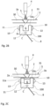
- Fig. 1 shows in conjunction with Fig. 2A an embodiment of a purging apparatus 1 according to the present invention for purging a root 2a of a weld seam 2 formed along a surface region 3a of a workpiece 3 upon welding.
- the weld seam 2 can be welded using a welding torch 4 generating an arc 5 (or a plasma jet 6, cf. Fig. 3 ).
- all suitable welding techniques can be used.
- the workpiece 3 comprises two parts 30, 31 that are connected by the weld seam 2.
- the purging apparatus 1 comprises an elongated rail 10 forming a groove 11 for guiding a purging gas G, the rail 10 being formed by a plurality of segments 100, 101 connected to one another, for example by hinges, so that the rail 10 can be adapted to a curvature of said surface region 3a of the at least one workpiece 3 by adjusting the angles between each two neighbouring segments 100 accordingly.
- the segments 100 of the rail 10 can also be rigidly connected to one another via their end surfaces 100a, wherein segments 100 can have at least one angled end surface 100a to adjust the curvature of the rail 10 to the curvature of the workpiece 3. Particularly, an angle of the respective end surface is chosen to fit to the pipe / workpiece diameter.
- the groove 11 of the adaptable rail 10 being formed by the interconnected segments 100 is delimited by a face side 10a of the rail 10, which face side 10a is configured to be pressed against said surface region 3a of the workpiece 3 to form the groove 11 into a channel through which the purging gas G can be passed along the root 2a to purge the root 2a of the weld seam 2 upon welding the weld seam 2.
- a metallic mesh 11a or perforated plate 11a can be used to close the groove 11 at the face side 10a of the rail 10 as shown in Fig. 2C .
- the gas can also be distributed to every single or second segment 100 of the rail 10 individually and distributed locally by e.g., a gas silencer.
- the purging apparatus 1 can also be operated without contact to the workpiece 3 as shown in Fig. 2B .
- the rail 10 being formed from multiple segments 100 is a modular device that can be easily adapted to the workpiece 3.
- the workpiece 3 is a pipe, with the parts 30, 31 forming sections of the pipe.
- the curvature of the rail 10 can be adapted to the inner radius of the pipe 3 as shown in Fig. 1 .
- the number of individual segments 100 can be selected so as to adjust the length of the rail 10 appropriately.
- the rail 10 is variable in length and radius.
- the rail 10 can be pressed directly against the underside of the component 3 by means of a holding device such as an arm (e.g. cantilever), cf. Fig. 1 .
- the respective segment 100 can be cooled with a cooling medium C, particularly cooling liquid, such as water so that heat can be dissipated from the component 3.
- a cooling medium C particularly cooling liquid, such as water so that heat can be dissipated from the component 3.
- the segments 100 can form a conduit 12 for guiding the cooling medium C.
- gas cooling nozzles 13 can be integrated to further cool the component 3.
- the purging gas G can be delivered from a container 7 via a piping to the rail 10 and directed from front to back so that a high relative flow occurs along the component surface 3a. This further improves the cooling effect and prevents the deposition of evaporation.
- one of the segments 101 of the rail 10 comprises a through-hole 102 (e.g., in the centre of the segment 101) connecting the groove 11 to the bottom side 101a of the segment, so that the plasma jet 6 of the welding torch 4 can escape from the segment 101 through this through-hole 102.
- the through-hole 102 is arranged below the tap hole 32 formed in the workpiece 3 by the plasma jet 6.
- the segment 101 is well cooled and is preferably made of a material with good thermal conductivity, such as copper.
- a heat absorber that is well cooled and made of a material with good thermal conductivity, such as copper can be used.
- sensors in the rail 10, particularly in the segment 101 can be used to optimize the cooling effect as well as the purging effect e.g., based on the O 2 content or temperature of the root 2a.
- the positioning of the rail 10 can be conducted based on a holding device 8 such as a static arm as shown in Fig. 1 .
- the rail 10 is located below the welding torch 4.
- the purging gas G is fed over the already welded seam 2.
- the torch and fixture are stationary, the tube moves relative to it in a direction D indicated in Fig. 3 .
- the rail 10 is moved synchronously with the torch 4.
- the present invention allows to perform welding tasks in complex geometries with less oxidation or no oxidation at all. Purging times are drastically reduced and deposits can be avoided.
- a single adaptable rail can be fitted to different geometries of the workpiece to be welded.
Landscapes
- Engineering & Computer Science (AREA)
- Physics & Mathematics (AREA)
- Mechanical Engineering (AREA)
- Plasma & Fusion (AREA)
- Optics & Photonics (AREA)
- Butt Welding And Welding Of Specific Article (AREA)
Abstract
The present invention relates to a purging apparatus (1) for purging a root (2a) of a weld seam (2) formed along a surface region (3a) of a workpiece (3) upon welding, the purging apparatus (1) comprising an elongated rail (10) forming a groove (11) for guiding a purging gas (G), the rail (10) being formed by a plurality of segments (100, 101) connected to one another so that the rail (10) can be adapted to a curvature of said surface region (3a) of the at least one workpiece (3), the groove (11) being delimited by a face side (10a) of the rail (10), the face side (10a) configured to contact said surface region (3a) of the at least one workpiece (3) to form a channel through which the purging gas (G) can be passed to purge the root (2a) of the weld seam (2) upon welding the weld seam (2).
Description
- The present invention relates to a purging apparatus and to a corresponding method.
- Oxidation of the underside of a weld seam, i.e. of the root of the weld seam often occurs during welding. To prevent this oxidation a purging gas is used (also called root gas) to cover the root of the weld seam and prevent oxidation. Particularly, in case of longitudinal weld seams the underside of the seam is usually pressed onto a rail that comprises a groove through which said gas is passed so that the gas covers the root of the weld seam.
- In this way, atmospheric gas at the root is displaced so that oxidation of the root of the weld seam can be reliably avoided. The purging gases used are typically argon, nitrogen and gas mixtures with hydrogen.
- However, the use of the afore-mentioned rails is not possible for curved components (e.g. pipes) or for components with a complex geometry. For this reason, in case of such curved workpieces the entire interior is usually flooded with the purging gas or a displacement body is used and continuously flushed. Complete purging of the interior has the disadvantage that the purging times and the gas requirement are large. If displacement bodies are used, they must be adapted for each individual geometry of the component to be welded.
- Alternatively, large-volume components are brushed or pickled after welding in order to eliminate the tarnish.
- Thus, purging methods in case of more complex geometries usually require a more involved purging procedure and is thus less efficient, often bears the risk of dead spaces and complex safety aspects. Particularly, displacement bodies can only be used up to a certain diameter due to the fact that they are unprofitable for a large diameter. In case of heat sources forming a keyhole, destruction of the displacement would occur and keyhole welding is not possible. Furthermore, displacement bodies often also cause accessibility problems.
- Based on the above, the problem to be solved by the present invention is to provide a purging apparatus and a corresponding method that are improved regarding the above-stated disadvantages.
- This problem is solved by a purging apparatus having the features of
claim 1 as well as by a method having the features of claim 9. - Preferred embodiments of these aspects of the present invention are stated in the corresponding sub claims and are described below.
- According to
claim 1, a purging apparatus for purging a root of a weld seam formed along a surface region of a workpiece upon welding is disclosed, the purging apparatus comprising an elongated rail forming a groove for guiding a purging gas, the rail being formed by a plurality of segments pivotably connected to one another so that the rail can be adapted to a curvature of said surface region of the at least one workpiece, the groove being delimited by a face side of the rail, the face side configured to contact said surface region of the at least one workpiece to form a channel through which the purging gas can be passed to purge the root of the weld seam upon welding the weld seam. - According to an embodiment of the present invention, the purging apparatus comprises a holding device for pressing the rail with the face side against said surface region. Particularly, in an embodiment, the holding device comprises an arm, particularly a cantilever for pressing the adaptable rail against said surface region.
- Further, in an embodiment, the rail is configured to guide a cooling liquid to cool the rail.
- Furthermore, according to an embodiment, the rail comprises cooling gas nozzles to cool the workpiece by discharging a cooling gas onto the workpiece through the cooling gas nozzles.
- Further, in an embodiment, the rail comprises a conduit for receiving a cooling liquid to cool the rail upon welding.
- Furthermore, according to an embodiment, one of the segments comprises a through-hole connecting the groove to a bottom side of the segment to allow passage of a plasma jet through the through-hole of the segment upon welding said weld seam using [keyhole technique] plasma welding. Preferably, in an embodiment, said segment is formed out of a metal, particularly copper.
- Further, according to an embodiment, the respective segment comprises at least one end surface via which the segment is rigidly connected to a neighbouring segment, wherein an angle of the respective end surface is selected so as to adapt the rail to the curvature of said surface region.
- According to yet another embodiment, the purging apparatus comprises a metallic mesh or a perforated plate covering the groove at the face side of the rail.
- Yet a further aspect of the present invention relates to a method for purging a root of a weld seam formed along a surface region of a workpiece using a purging apparatus according to one of the preceding claims, the method comprising the steps of:
- arranging the rail along said surface region, and
- allowing a purging gas to flow through the groove along the root of the weld seam upon welding of the weld seam.
- According to an embodiment of the method, the weld seam is welded using a plasma arc, wherein a plasma jet generated upon welding is allowed to pass through said through-hole of said segment of the rail, and wherein purging gas is passed through the groove along the root of an already welded portion of the weld seam.
- Furthermore, in an embodiment of the method, for welding the weld seam, the work piece is moved relative to the rail and a welding torch, the welding torch and the rail being stationary with respect to one another.
- Further, according to an embodiment of the method, upon welding the weld seam the workpiece is stationary and the rail and a welding torch are moved relative to the workpiece synchronously with respect to one another.
- In the following embodiments of the present invention as well as further features and advantages shall be described with reference to the Figures, wherein
- Fig. 1
- shows an embodiment to a purging apparatus according to the present invention;
- Fig. 2A
- shows a cross section along the plane II-II of
Fig. 1 ; - Fig. 2B
- shows a further cross section along the plane II-II of
Fig. 1 , wherein here the purging apparatus is used being spaced apart from the surface of the workpiece, - Fig. 2C
- shows a further cross section along the plane II-II of
Fig. 1 , wherein here the purging apparatus comprises a metallic mesh or perforated plate covering the groove at the face side of the rail, and - Fig. 3
- shows an embodiment of the purging apparatus that can be used when plasma welding using a keyhole technique.
-
Fig. 1 shows in conjunction withFig. 2A an embodiment of a purgingapparatus 1 according to the present invention for purging aroot 2a of aweld seam 2 formed along asurface region 3a of aworkpiece 3 upon welding. Particularly, theweld seam 2 can be welded using awelding torch 4 generating an arc 5 (or aplasma jet 6, cf.Fig. 3 ). Particularly, all suitable welding techniques can be used. Here, particularly, theworkpiece 3 comprises twoparts weld seam 2. The purgingapparatus 1 comprises anelongated rail 10 forming agroove 11 for guiding a purging gas G, therail 10 being formed by a plurality ofsegments rail 10 can be adapted to a curvature of saidsurface region 3a of the at least oneworkpiece 3 by adjusting the angles between each two neighbouringsegments 100 accordingly. Furthermore, instead of using hinges, thesegments 100 of therail 10 can also be rigidly connected to one another via theirend surfaces 100a, whereinsegments 100 can have at least oneangled end surface 100a to adjust the curvature of therail 10 to the curvature of theworkpiece 3. Particularly, an angle of the respective end surface is chosen to fit to the pipe / workpiece diameter. - Further, the
groove 11 of theadaptable rail 10 being formed by the interconnectedsegments 100 is delimited by aface side 10a of therail 10, whichface side 10a is configured to be pressed against saidsurface region 3a of theworkpiece 3 to form thegroove 11 into a channel through which the purging gas G can be passed along theroot 2a to purge theroot 2a of theweld seam 2 upon welding theweld seam 2. - A
metallic mesh 11a orperforated plate 11a can be used to close thegroove 11 at theface side 10a of therail 10 as shown inFig. 2C . Further, instead of purging the gas from one end to the other, the gas can also be distributed to every single orsecond segment 100 of therail 10 individually and distributed locally by e.g., a gas silencer. In this case the purgingapparatus 1 can also be operated without contact to theworkpiece 3 as shown inFig. 2B . - Advantageously, the
rail 10 being formed frommultiple segments 100 is a modular device that can be easily adapted to theworkpiece 3. Particularly theworkpiece 3 is a pipe, with theparts rail 10 can be adapted to the inner radius of thepipe 3 as shown inFig. 1 . - Furthermore, generally, the number of
individual segments 100 can be selected so as to adjust the length of therail 10 appropriately. Thus, therail 10 is variable in length and radius. According to an embodiment, therail 10 can be pressed directly against the underside of thecomponent 3 by means of a holding device such as an arm (e.g. cantilever), cf.Fig. 1 . - According to an embodiment, the
respective segment 100 can be cooled with a cooling medium C, particularly cooling liquid, such as water so that heat can be dissipated from thecomponent 3. Particularly, thesegments 100 can form aconduit 12 for guiding the cooling medium C. - In addition, gas cooling nozzles 13 (cf.
Fig. 2 ) can be integrated to further cool thecomponent 3. The purging gas G can be delivered from a container 7 via a piping to therail 10 and directed from front to back so that a high relative flow occurs along thecomponent surface 3a. This further improves the cooling effect and prevents the deposition of evaporation. - As shown in
Fig. 3 , for plasma welding in the keyhole technique, one of thesegments 101 of therail 10 comprises a through-hole 102 (e.g., in the centre of the segment 101) connecting thegroove 11 to thebottom side 101a of the segment, so that theplasma jet 6 of thewelding torch 4 can escape from thesegment 101 through this through-hole 102. Accordingly, the through-hole 102 is arranged below thetap hole 32 formed in theworkpiece 3 by theplasma jet 6. Furthermore, preferably, thesegment 101 is well cooled and is preferably made of a material with good thermal conductivity, such as copper. Instead of a through-hole 102 a heat absorber that is well cooled and made of a material with good thermal conductivity, such as copper can be used. - Further, sensors in the
rail 10, particularly in thesegment 101, can be used to optimize the cooling effect as well as the purging effect e.g., based on the O2 content or temperature of theroot 2a. - In all embodiments, the positioning of the
rail 10 can be conducted based on aholding device 8 such as a static arm as shown inFig. 1 . In this case therail 10 is located below thewelding torch 4. The purging gas G is fed over the already weldedseam 2. The torch and fixture are stationary, the tube moves relative to it in a direction D indicated inFig. 3 . - Alternatively, in case the
welding torch 4 is moved and theworkpiece 3 rests, therail 10 is moved synchronously with thetorch 4. - Advantageously, the present invention allows to perform welding tasks in complex geometries with less oxidation or no oxidation at all. Purging times are drastically reduced and deposits can be avoided. A single adaptable rail can be fitted to different geometries of the workpiece to be welded.
Claims (12)
- A purging apparatus (1) for purging a root (2a) of a weld seam (2) formed along a surface region (3a) of a workpiece (3) upon welding, the purging apparatus (1) comprising an elongated rail (10) forming a groove (11) for guiding a purging gas (G), the rail (10) being formed by a plurality of segments (100, 101) connected to one another so that the rail (10) can be adapted to a curvature of said surface region (3a) of the at least one workpiece (3), the groove (11) being delimited by a face side (10a) of the rail (10), the face side (10a) configured to contact said surface region (3a) of the at least one workpiece (3) to form a channel through which the purging gas (G) can be passed to purge the root (2a) of the weld seam (2) upon welding the weld seam (2).
- The purging apparatus according to claim 1, wherein the purging apparatus comprises a holding device (8) for pressing the rail (10) with the face side (10a) against said surface region (3a).
- The purging apparatus according to one of the preceding claims, wherein the rail (10) comprises a conduit (12) for receiving a cooling medium (C) to cool the rail (10) [upon welding]
- The purging apparatus according to one of the preceding claims, wherein the rail (10) comprises cooling gas nozzles (13) to cool the workpiece by discharging a cooling gas onto the workpiece (3) through the cooling gas nozzles (13).
- The purging apparatus according to one of the preceding claims, wherein one of the segments (101) comprises a through-hole (102) connecting the groove (11) to a bottom side (101a) of the segment (101) to allow passage of a plasma jet (6) through the through-hole (102) of the segment (101) upon welding said weld seam (2) using the plasma jet (6).
- The purging apparatus according to claim 5, wherein said segment (101) is formed out of a metal, particularly copper.
- The purging apparatus according to one of the preceding claims, wherein the respective segment (100) comprises at least one end surface (100a) via which the segment (100) is rigidly connected to a neighbouring segment (100), wherein an angle of the respective end surface (100a) is selected so as to adapt the rail (10) to the curvature of said surface region (3a).
- The purging apparatus according to one of the preceding claims. wherein the purging apparatus (1) comprises a metallic mesh (11a) or a perforated plate (11a) covering the groove (11) at the face side (10a) of the rail (10).
- A method for purging a root (2a) of a weld seam (2) formed along a surface region (3a) of a workpiece (3) using a purging apparatus (1) according to one of the preceding claims, the method comprising the steps of:- arranging the rail (10) along said surface region (3a), and- allowing a purging gas (G) to flow through the groove (11) along the root (2a) of the weld seam (2) upon welding of the weld seam (2).
- The method according to claim 9, wherein the weld seam (2) is welded using a plasma arc (6), wherein a generated plasma jet (6a) is allowed to pass through said through-hole (102) of said segment (101) of the rail (10), and wherein purging gas (G) is passed through the groove (11) along the root (2a) of an already welded portion of the weld seam (2).
- The method according to claim 9 or 10, wherein for welding the weld seam (2), the workpiece (3) is moved relative to the rail (10) and a welding torch (4), the welding torch (4) and the rail (10) being stationary with respect to one another
- The method according to claim 9 or 10, wherein upon welding the weld seam (2) the workpiece (3) is stationary and the rail (10) and a welding torch (4) are moved relative to the workpiece (3) synchronously with respect to one another.
Priority Applications (2)
| Application Number | Priority Date | Filing Date | Title |
|---|---|---|---|
| EP21020464.0A EP4151348A1 (en) | 2021-09-16 | 2021-09-16 | Modular purging |
| PCT/EP2022/025431 WO2023041197A1 (en) | 2021-09-16 | 2022-09-15 | Modular purging |
Applications Claiming Priority (1)
| Application Number | Priority Date | Filing Date | Title |
|---|---|---|---|
| EP21020464.0A EP4151348A1 (en) | 2021-09-16 | 2021-09-16 | Modular purging |
Publications (1)
| Publication Number | Publication Date |
|---|---|
| EP4151348A1 true EP4151348A1 (en) | 2023-03-22 |
Family
ID=77838658
Family Applications (1)
| Application Number | Title | Priority Date | Filing Date |
|---|---|---|---|
| EP21020464.0A Withdrawn EP4151348A1 (en) | 2021-09-16 | 2021-09-16 | Modular purging |
Country Status (2)
| Country | Link |
|---|---|
| EP (1) | EP4151348A1 (en) |
| WO (1) | WO2023041197A1 (en) |
Families Citing this family (2)
| Publication number | Priority date | Publication date | Assignee | Title |
|---|---|---|---|---|
| CN116441679A (en) * | 2023-05-29 | 2023-07-18 | 华能(上海)电力检修有限责任公司 | Argon tungsten-arc welding plate-shaped protective cover and tubular protective cover |
| CN116765571B (en) * | 2023-07-05 | 2025-09-02 | 江苏徐工工程机械研究院有限公司 | Welding pad, system and method of use |
Citations (5)
| Publication number | Priority date | Publication date | Assignee | Title |
|---|---|---|---|---|
| SU743809A1 (en) * | 1978-03-24 | 1980-06-30 | Предприятие П/Я А-1944 | Gas-shielding arrangement for welding |
| DE9306578U1 (en) * | 1993-05-01 | 1993-07-01 | Otto Tuchenhagen GmbH & Co KG, 2059 Büchen | Device for applying gas to form weld seams in gas shielded welding processes |
| US5256847A (en) * | 1992-08-12 | 1993-10-26 | Intevep, S.A. | TIG shielded atmosphere welding system |
| DE102016220509A1 (en) * | 2016-10-19 | 2018-04-19 | Kjellberg-Stiftung | Schleppgasdüse |
| US10160054B2 (en) * | 2015-03-10 | 2018-12-25 | Senior Ip Gmbh | Instantaneous gas purge apparatus |
-
2021
- 2021-09-16 EP EP21020464.0A patent/EP4151348A1/en not_active Withdrawn
-
2022
- 2022-09-15 WO PCT/EP2022/025431 patent/WO2023041197A1/en not_active Ceased
Patent Citations (5)
| Publication number | Priority date | Publication date | Assignee | Title |
|---|---|---|---|---|
| SU743809A1 (en) * | 1978-03-24 | 1980-06-30 | Предприятие П/Я А-1944 | Gas-shielding arrangement for welding |
| US5256847A (en) * | 1992-08-12 | 1993-10-26 | Intevep, S.A. | TIG shielded atmosphere welding system |
| DE9306578U1 (en) * | 1993-05-01 | 1993-07-01 | Otto Tuchenhagen GmbH & Co KG, 2059 Büchen | Device for applying gas to form weld seams in gas shielded welding processes |
| US10160054B2 (en) * | 2015-03-10 | 2018-12-25 | Senior Ip Gmbh | Instantaneous gas purge apparatus |
| DE102016220509A1 (en) * | 2016-10-19 | 2018-04-19 | Kjellberg-Stiftung | Schleppgasdüse |
Also Published As
| Publication number | Publication date |
|---|---|
| WO2023041197A1 (en) | 2023-03-23 |
Similar Documents
| Publication | Publication Date | Title |
|---|---|---|
| WO2023041197A1 (en) | Modular purging | |
| US20080296271A1 (en) | Method and Apparatus for Laser Welding | |
| US20170120398A1 (en) | Welding apparatus | |
| JP2009107017A (en) | Method for controlling weld quality | |
| Boulos et al. | Plasma torches for cutting, welding, and PTA coating | |
| US20030121893A1 (en) | Process and apparatus for cutting or welding a workpiece | |
| KR20210110810A (en) | Torch with gas nozzle and gas nozzle for outflow of the shielding gas stream | |
| RU2750387C1 (en) | Device for gas protection of weld during laser welding | |
| EP1356890A1 (en) | Method of metal working/welding assisted by cryogen flow | |
| EP4263104A1 (en) | Modular trailing nozzle system for a welding torch | |
| GB2308562A (en) | Underwater welding method and apparatus | |
| JP2009269064A (en) | Gas metal enclosed welding equipment for bar-shaped member | |
| KR20190077757A (en) | Device and method for welding steel material | |
| JP2006007301A (en) | Welding device with cooling mechanism | |
| JP2007237213A (en) | Welding torch and welding system using welding torch | |
| CN106514069A (en) | Device inhibiting welding defects of small-diameter aluminum alloy guiding pipe | |
| JPH10291069A (en) | Method and device for butt welding | |
| CA2644189A1 (en) | Nozzle/wire guide assembly for robotic tig welding torch | |
| JPH1190634A (en) | Stainless steel member welding method and welding aid used in this welding method | |
| KR20240123324A (en) | Welding Torch | |
| JP2023067480A (en) | Welding jig, welding device and welding method | |
| US3473002A (en) | Triply shielded arc welding method | |
| US3524039A (en) | Copper welding process | |
| JP4646464B2 (en) | TIG welding equipment | |
| JP2007190595A (en) | Inner shield jig for metal welded pipe manufacturing |
Legal Events
| Date | Code | Title | Description |
|---|---|---|---|
| PUAI | Public reference made under article 153(3) epc to a published international application that has entered the european phase |
Free format text: ORIGINAL CODE: 0009012 |
|
| STAA | Information on the status of an ep patent application or granted ep patent |
Free format text: STATUS: THE APPLICATION HAS BEEN PUBLISHED |
|
| AK | Designated contracting states |
Kind code of ref document: A1 Designated state(s): AL AT BE BG CH CY CZ DE DK EE ES FI FR GB GR HR HU IE IS IT LI LT LU LV MC MK MT NL NO PL PT RO RS SE SI SK SM TR |
|
| STAA | Information on the status of an ep patent application or granted ep patent |
Free format text: STATUS: THE APPLICATION IS DEEMED TO BE WITHDRAWN |
|
| 18D | Application deemed to be withdrawn |
Effective date: 20230923 |