EP4151138A1 - Aussenschaft für ein endoskop und endoskopiesystem - Google Patents
Aussenschaft für ein endoskop und endoskopiesystem Download PDFInfo
- Publication number
- EP4151138A1 EP4151138A1 EP22193396.3A EP22193396A EP4151138A1 EP 4151138 A1 EP4151138 A1 EP 4151138A1 EP 22193396 A EP22193396 A EP 22193396A EP 4151138 A1 EP4151138 A1 EP 4151138A1
- Authority
- EP
- European Patent Office
- Prior art keywords
- endoscope
- proximal end
- outer shaft
- shaft
- end area
- Prior art date
- Legal status (The legal status is an assumption and is not a legal conclusion. Google has not performed a legal analysis and makes no representation as to the accuracy of the status listed.)
- Granted
Links
Images
Classifications
-
- A—HUMAN NECESSITIES
- A61—MEDICAL OR VETERINARY SCIENCE; HYGIENE
- A61B—DIAGNOSIS; SURGERY; IDENTIFICATION
- A61B1/00—Instruments for performing medical examinations of the interior of cavities or tubes of the body by visual or photographical inspection, e.g. endoscopes; Illuminating arrangements therefor
- A61B1/012—Instruments for performing medical examinations of the interior of cavities or tubes of the body by visual or photographical inspection, e.g. endoscopes; Illuminating arrangements therefor characterised by internal passages or accessories therefor
- A61B1/018—Instruments for performing medical examinations of the interior of cavities or tubes of the body by visual or photographical inspection, e.g. endoscopes; Illuminating arrangements therefor characterised by internal passages or accessories therefor for receiving instruments
-
- A—HUMAN NECESSITIES
- A61—MEDICAL OR VETERINARY SCIENCE; HYGIENE
- A61B—DIAGNOSIS; SURGERY; IDENTIFICATION
- A61B1/00—Instruments for performing medical examinations of the interior of cavities or tubes of the body by visual or photographical inspection, e.g. endoscopes; Illuminating arrangements therefor
- A61B1/00064—Constructional details of the endoscope body
- A61B1/00105—Constructional details of the endoscope body characterised by modular construction
-
- A—HUMAN NECESSITIES
- A61—MEDICAL OR VETERINARY SCIENCE; HYGIENE
- A61B—DIAGNOSIS; SURGERY; IDENTIFICATION
- A61B1/00—Instruments for performing medical examinations of the interior of cavities or tubes of the body by visual or photographical inspection, e.g. endoscopes; Illuminating arrangements therefor
- A61B1/00112—Connection or coupling means
- A61B1/00121—Connectors, fasteners and adapters, e.g. on the endoscope handle
- A61B1/00128—Connectors, fasteners and adapters, e.g. on the endoscope handle mechanical, e.g. for tubes or pipes
-
- A—HUMAN NECESSITIES
- A61—MEDICAL OR VETERINARY SCIENCE; HYGIENE
- A61B—DIAGNOSIS; SURGERY; IDENTIFICATION
- A61B1/00—Instruments for performing medical examinations of the interior of cavities or tubes of the body by visual or photographical inspection, e.g. endoscopes; Illuminating arrangements therefor
- A61B1/00131—Accessories for endoscopes
- A61B1/00135—Oversleeves mounted on the endoscope prior to insertion
-
- G—PHYSICS
- G02—OPTICS
- G02B—OPTICAL ELEMENTS, SYSTEMS OR APPARATUS
- G02B23/00—Telescopes, e.g. binoculars; Periscopes; Instruments for viewing the inside of hollow bodies; Viewfinders; Optical aiming or sighting devices
- G02B23/24—Instruments or systems for viewing the inside of hollow bodies, e.g. fibrescopes
- G02B23/2407—Optical details
- G02B23/2423—Optical details of the distal end
- G02B23/243—Objectives for endoscopes
-
- A—HUMAN NECESSITIES
- A61—MEDICAL OR VETERINARY SCIENCE; HYGIENE
- A61B—DIAGNOSIS; SURGERY; IDENTIFICATION
- A61B1/00—Instruments for performing medical examinations of the interior of cavities or tubes of the body by visual or photographical inspection, e.g. endoscopes; Illuminating arrangements therefor
- A61B1/00064—Constructional details of the endoscope body
- A61B1/00103—Constructional details of the endoscope body designed for single use
-
- A—HUMAN NECESSITIES
- A61—MEDICAL OR VETERINARY SCIENCE; HYGIENE
- A61B—DIAGNOSIS; SURGERY; IDENTIFICATION
- A61B1/00—Instruments for performing medical examinations of the interior of cavities or tubes of the body by visual or photographical inspection, e.g. endoscopes; Illuminating arrangements therefor
- A61B1/00112—Connection or coupling means
Definitions
- the present invention relates to an outer shaft for an endoscope and to an endoscopy system with an outer shaft and an endoscope.
- EP 1 542 579 B1 , EP 2 552 293 B1 , WO 2018/165365 A2 and WO 2019/126683 A1 describes medical instruments with long, thin shafts which, in addition to devices for capturing and transmitting images, also have one or more fluid channels for conducting rinsing fluid or for sucking fluid from a site.
- an outer shaft can be slipped over the shaft of an endoscope.
- a jacket-shaped fluid channel remains between the outer shaft and the shaft of the endoscope, with a particularly essentially annular cross-section, through which a flushing fluid can be conducted to the distal end or a fluid can be sucked out of the distal end of the arrangement.
- the endoscope In the transition area between the proximal end of the shaft and the distal end of the handling device, the endoscope has, for example, convex areas to which the proximal end of the outer shaft can be attached. Slidable, pivotable or rotatable latches at the proximal end of the outer shaft enable a detachable mechanical connection.
- One object of the present invention is to provide an improved outer shaft for an endoscope and an improved endoscopy system.
- An outer shaft for receiving a shaft of an endoscope comprises a proximal end area for receiving a proximal end area of the shaft of the endoscope, a sealing surface for abutting against a corresponding sealing surface of the endoscope for locally fluid-tight sealing of an intermediate space between the outer shaft and the shaft of the endoscope, and a radially inwardly projecting Catch in the proximal end area for proximally reaching behind a radially outwardly protruding catch on the proximal end area of the shaft of the endoscope, the radially inwardly protruding catch being provided on a section of the proximal end area of the outer shaft that is elastically deformable in the axial direction of the outer shaft.
- the outer shaft is both factual due to its length, the cross-section of its lumen and the geometry of the sealing surface and the radially inward projecting lug, and legally due to its specific medical device approval for exclusive use with an endoscope of a predetermined type or a type from a predetermined group provided and trained by types.
- the type or group of types is clearly identified in the medical device approval.
- the outer shaft can be provided to form an endoscopy system from the outer shaft and an endoscope for various medical measures.
- Both the outer shaft and the shaft of the endoscope can be rigid and straight or curved or flexible in sections or completely.
- the intermediate space between the outer shaft and the shaft of the endoscope has, in particular, at least in sections, a ring-shaped, for example circular, cross-section and extends to a distal end of the arrangement of the outer shaft and the shaft of the endoscope.
- the gap can be used both for conducting a flushing fluid to this be provided and designed distal end as well as for sucking a fluid from there.
- the intermediate space between the outer shaft and the shaft of the endoscope can have an enlarged cross section in the proximal end area and merge into a fluid connection, for example arranged radially.
- the sealing surface on the outer shaft and the corresponding sealing surface of the endoscope when they are in contact with one another, seal the proximal end of the space between the outer shaft and the shaft of the endoscope in a fluid-tight manner.
- the sealing surface of the outer shaft is in particular concavely conical and the sealing surface of the endoscope is convexly conical, with the diameter and opening angle being identical or similar.
- the lug projecting radially inward in the proximal end area of the outer shaft and the lug projecting radially outward on the proximal end area of the shaft of the endoscope are each designed in particular as straight or curved webs with trapezoidal or rectangular cross sections.
- the radially inwardly projecting lug in the proximal end area of the outer shaft is proximal to the radially outwardly projecting lug on the proximal end area of the shaft of the endoscope arranged.
- the elastically deformable section is elastically deformed in the proximal direction.
- the resulting elastic restoring force presses a distally oriented surface area of the radially inwardly projecting lug of the outer shaft against a proximally oriented surface area of the radially outwardly projecting lug on the proximal end area of the shaft.
- the sealing surface on the outer shaft is pressed against the sealing surface of the endoscope at the same time.
- the outer shaft has a particularly simple mechanical structure with the radially inwardly projecting catch on the elastically deformable section of the proximal end region of the outer shaft.
- no moving parts are required to connect the outer shaft and the endoscope. This can enable cost-effective production and great mechanical robustness.
- the outer shaft or at least the proximal end area of the outer shaft, including the elastically deformable section and the radially inwardly projecting lug can be produced monolithically, for example as a cast part, in particular as an injection-molded part.
- the elastically deformable section of the proximal end area essentially has the shape of a straight or curved bar which is connected to the remaining proximal end area at one end or at both of its ends.
- the elastically deformable section has in particular the shape of a bar which is parallel or substantially parallel to a plane orthogonal to the longitudinal axis of the outer upper.
- the elastically deformable section is designed as a curved bar that is arranged in the direction of the circumference of the proximal end area and follows the contour of the proximal end area.
- the elastically deformable section is in particular elastically bent and/or twisted when the outer shaft is attached to the endoscope.
- both ends of the elastically deformable section are connected to the remaining proximal end region of the outer shaft, the elastically deformable section having increased elastic flexibility near its ends.
- the elastically deformable section has reduced cross sections, in particular near its two ends.
- the elastically deformable portion is elastically deformed in a first direction near its ends and in a second, opposite direction between its ends.
- the elastically deformable section is separated from the rest of the proximal end region in particular by a slot running essentially in the circumferential direction of the proximal end region of the outer shaft.
- the slot can have a constant width or a width that can vary in its longitudinal direction.
- the ends of the slot define the ends of the elastically deformable portion.
- a groove can be provided, which locally significantly reduces the wall thickness of the proximal end area and thus locally increases the elasticity of the proximal end area.
- the groove starts in particular from the inside of the proximal end area.
- the proximal end area of the outer shaft is in particular essentially funnel-shaped or cup-shaped and open towards the proximal end.
- the proximal edge of the proximal end area of the outer shaft lies in particular in a plane orthogonal to the longitudinal axis of the outer shaft.
- the radially inwardly projecting lug projects in particular into the cavity circumscribed in a funnel-shaped or cup-shaped manner by the proximal end region.
- the lug projecting radially inwards is arranged in particular near the proximal edge or directly adjacent to the proximal edge of the proximal end region of the outer shaft.
- the proximal end area has in particular a niche running in the axial direction and open radially inward for the passage of the radially outwardly projecting lug on the proximal end area of the endoscope shaft during the axial insertion of the endoscope shaft into the outer shaft, wherein the radially inwardly projecting lug of the outer shaft is designed and arranged to slide during a rotation of the outer shaft relative to the endoscope on the radially outwardly projecting lug of the endoscope to a position proximal to the radially outward during axial insertion protruding cleat of the endoscope.
- the niche is designed in particular as a groove which is wide in the circumferential direction, flat in the radial direction and short in the axial direction.
- the cross section of the niche running in the axial direction and open radially inwards is adapted in particular to the cross section of the radially outwardly protruding lug of the endoscope, with the cross sections each being on a sectional plane orthogonal to the longitudinal axis of the outer shaft and the shaft of the Endoscope related.
- An outer shaft as described here, also includes in particular a ramp surface on the lug of the outer shaft for generating a force that deforms the elastically deformable section in the axial direction of the outer shaft when the outer shaft rotates relative to the endoscope.
- the ramp surface essentially runs in the circumferential direction, but is inclined relative to a plane orthogonal to the longitudinal axis of the outer upper.
- the angle between the ramp surface and the plane orthogonal to the longitudinal axis of the outer upper depends on the elasticity of the elastically deformable section and the resulting restoring force and thus in particular on the geometry and the material of the elastically deformable section.
- the angle is in particular in the range from 5° to 40° or in the range from 10° to 30°.
- An outer upper as it is described here, also includes in particular a plateau surface that merges into the ramp surface on the lug of the outer upper.
- the lug of the endoscope which protrudes radially outwards, rests in particular on the plateau surface on the lug of the outer shaft.
- the elastic restoring force of the elastically deformable section presses the radially inwardly projecting lug of the outer shaft in the axial direction against the Radially outwardly projecting lug of the endoscope and the sealing surface of the outer shaft against the corresponding sealing surface of the endoscope and thus locks the outer shaft in terms of rotation relative to the endoscope by friction.
- Frictional engagement can occur between the involved surface areas of the radially inwardly projecting lug of the outer shaft and the radially outwardly projecting lug of the endoscope, and due to the conicity especially between the sealing surface of the outer shaft and the corresponding sealing surface of the endoscope.
- the frictional connection between the concavely conical sealing surface of the outer shaft and the convexly conical corresponding sealing surface of the endoscope can be strong enough to make a latching or another partially or completely form-fitting locking superfluous.
- a detent or another positive locking mechanism can be provided. Depending on the tribological properties of the materials used and their surfaces, this may be necessary or advantageous.
- the outer shaft in particular the outer shaft, including the lug projecting radially inwards, is made of plastic and is intended and designed for single use.
- the outer socket cannot be autoclaved and therefore cannot be reused or not readily reused.
- the outer shaft is intended and designed in particular for use with a reusable endoscope, ie an endoscope that can be used several times.
- the outer shaft can be provided and designed for use with a disposable endoscope, i.e. an endoscope that is to be disposed of after use and is not intended for processing and reuse.
- each lug projecting radially inward is provided on an associated section of the proximal end region which is elastically deformable in the axial direction of the outer shaft.
- the plurality of lugs protruding radially inward and the plurality of elastically deformable sections are in particular distributed equally among one another and evenly over a circumference of the proximal end region.
- two radially inwardly projecting lugs are provided on each elastically deformable section and are arranged opposite one another.
- An endoscopy system comprises an outer shaft, as described here, and an endoscope with a shaft, a proximal end region, a sealing surface on the proximal end region of the endoscope that corresponds to the sealing surface of the outer shaft, and a radially outwardly projecting lug for gripping behind the radially inward protruding lug on the inside of the proximal end area of the outer shaft.
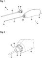
- figure 1 shows a schematic axonometric representation of an endoscopy system with an endoscope 10 and an outer shaft 40.
- the distal end 12 of the endoscope 10 is formed by a shaft 14, which is straight and rigid in the example shown.
- a handling device 16 forms the proximal end 18 of the endoscope 10. In a proximal end region 20 of the shaft 14, the shaft merges into the handling device 16.
- the outer shaft 40 comprises a shaft tube 44 and a proximal end region 50 with a fluid connection 52, which is designed as a flushing connection in the example shown.
- the cross section of the lumen of the outer shaft is adapted to the cross section of the shaft 14 of the endoscope such that the shaft 14 of the endoscope 10 can be completely inserted into the outer shaft 40 and its shaft tube 44, between the outer surface of the shaft 14 of the endoscope 10 and the inner surface of the outer shaft 40 a gap remains.
- This gap has, in particular, an annular or a C-shaped cross section and extends to the distal end 12 of the endoscope 10.
- a flushing fluid can be introduced into the outer shaft 40 through the flushing connection 52 and flows through the gap to the distal end 12 of the endoscope 10 flows and exits there.
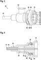
- FIG. 12 shows an enlarged schematic axonometric representation of part of the endoscope 10 of the endoscopy system figure 1 , namely the proximal end area 20 of the shaft 14 and the subsequent distal end of the handling device 16.
- an outer cone 24 and proximal to the outer cone 24 two lugs 26 are provided.
- the Knaggen 26 are on two Facing away from each other sides of the proximal end portion 20 is provided.
- each lug 26 has approximately the shape of a radially outwardly projecting web with a rectangular cross section.
- the outer contours of the lugs 26 are each in the form of an arc of a circle and form sections of the same circle, the center of which lies on the longitudinal axis and axis of symmetry of the shaft 14 .
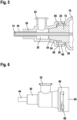
- FIG 3 shows a schematic and enlarged axonometric representation of the proximal end area 50 of the outer shaft of the endoscopy system figure 1 .
- the proximal end area 50 of the outer shaft 40 is permanently and rigidly mechanically connected to the shaft tube 44 of the outer shaft 40 .
- the outer shaft 40 can be formed monolithically, for example as a plastic injection molded part that includes both the shaft tube 44 and the proximal end area 50 .
- the shaft tube 44 can be joined to the proximal end region 50 of the outer shaft 40, for example by gluing or welding.
- the shaft tube 44 is made of metal and the proximal end area 50 of the outer shaft 40 is made of plastic.
- the flushing port 52 is arranged radially.
- the rinsing connection 52 can be designed as a Luer coupling.
- the proximal end area 50 of the outer shaft 40 is cup-shaped and has two opposing lugs 56 each protruding radially inwards.
- the lugs 56 have a large surface area, the depth of each lug 56 measured in the direction parallel to the longitudinal axis of the outer shaft 40 and the width of each lug 56 measured in the direction of the circumference is greater or significantly greater than the height of each lug measured in the radial direction 56.
- Each lug 56 is arranged on an elastically deformable section 60 of the proximal end area 50 of the outer shaft 40.
- Each elastically deformable section 60 essentially has the shape of a beam curved to follow the outer contour of the proximal end area 50 and is monolithically connected to the remaining proximal end area 50 via its ends 62, 64.
- One slit 66 separates each elastically deformable section 60 from the rest of the proximal end area 50. The ends of the slits 66 define the ends 62, 64 of the elastically deformable sections 60.
- radial recesses or niches 72 are provided in the circumferential direction between the lugs 56.
- the cross sections of the niches 72 are adapted to the cross sections of the lugs 26 on the proximal end area 20 of the endoscope 10 (cf. Figures 1, 2 ) adapted, wherein the cross-sections are viewed as cuts in planes orthogonal to the longitudinal axis of the outer shaft 40. Therefore, at the end of inserting the shaft 14 of the endoscope 10 (cf. Figures 1, 2 ) In the outer shaft 40, the lugs 26 on the proximal end area 20 of the endoscope 10 are moved in the axial direction through the niches 72 until they are arranged in one plane with the slots 66.
- the lugs 26 slide on the proximal end area 20 of the endoscope 10 (cf. Figures 1, 2 ) along ramp surfaces 74 on the lugs 56 and further along plateau surfaces 76 on the lugs 56 in the proximal end region 50 of the outer shaft 40 .
- the lugs 26 are arranged on the proximal end area 20 of the endoscope 10 distally of the lugs 56 in the proximal end area 50 of the outer shaft 40, the outer shaft 40 is held on the endoscope 10 in a form-fitting manner.
- the elastically deformable sections 60 are elastically deformed, namely the lugs 56 are displaced proximally. Elastic restoring forces of the elastically deformable sections 60 press the lugs 56 from the proximal end against the lugs 26 on the proximal end area 20 of the endoscope 10.
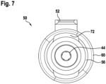
- figure 4 shows a schematic representation of a section through part of the endoscopy system from FIGS Figures 1 to 3 , namely through the proximal end portion 20 of the shaft 14 of the endoscope 10 and through the proximal end portion 50 of the outer shaft 40.
- the cutting plane of figure 4 contains the longitudinal and symmetry axes of the shaft 14 of the endoscope 10 and the shaft tube 44 of the outer shaft 40 and is orthogonal to the direction of extension of the rinsing connection 52.
- the sectional plane of the figure 4 cuts the lugs 26 on the proximal end area 20 of the shaft 14 of the endoscope 10 and the lugs 56 in the proximal end area 50 of the outer shaft 40.
- the proximal end area 50 of the outer shaft 40 has an inner cone 54 corresponding to the outer cone 24 on the proximal end area 20 of the shaft 14 of the endoscope 10 .
- FIG 4 the configuration intended for use of the endoscopy system is shown, in which the lugs 26 are arranged on the proximal end area 20 of the shaft 14 of the endoscope 10 distally of the lugs 56 in the proximal end area 50 of the outer shaft 40 .
- the elastically deformable portions 60 are elastically deformed while being displaced from their in figure 4 positions indicated by dashed lines in a mechanically stress-free state proximally into the in figure 4 positions shown in solid lines are shifted.
- the resulting elastic restoring force presses the lugs 56 in the proximal end area 50 of the outer shaft 40 from distally against the lugs 26 on the proximal end area 20 of the shaft 14 of the endoscope 10 and thus also the outer cone 24 on the proximal end area 20 of the shaft 14 against the inner cone 54 in the proximal end area 50 of the outer shaft 40.
- the surface normal force between them is increased compared to the elastic restoring force of the elastically deformed, elastically deformable sections 60.
- the resulting friction, in particular static friction between the lugs 26, 56 and above all between the outer cone 24 and inner cone 54 prevents an unintentional rotation of the outer shaft 40 relative to the endoscope 10 back to the configuration in which the lugs 26 on the proximal end region 20 of the shaft 14 of the endoscope 10 in the axial direction through the niches 72 (cf. figure 3 ) can be moved out of the proximal end region 50 of the outer shaft 40.
- the intermediate space 30 between the outer surface of the shaft 14 of the endoscope 10 and the inner surface of the outer shaft 40 can be seen.
- the intermediate space 30 extends with an annular cross section up to the distal end 12 of the endoscope 10 (cf. figure 1 ).
- the proximal end of the intermediate space 30 is enlarged in the form of a ring in the proximal end area 50 of the outer shaft 40 .
- the outer cone 24 on the proximal end portion 20 of the shaft 14 of the endoscope 10 and the inner cone 54 in the The proximal end region 50 of the outer shaft 40 is formed by sealing surfaces that rest against one another and close off the intermediate space 30 in a fluid-tight manner in the proximal direction.
- figure 5 shows a schematic representation of a further section through part of the endoscopy system from FIGS Figures 1 to 4 , namely the proximal end portion 20 of the shaft 14 of the endoscope 10 and the proximal end portion 50 of the outer shaft 40.
- the cutting plane of figure 5 contains the longitudinal and symmetrical axes of the shaft 14 of the endoscope 10 and the shaft tube 44 of the outer shaft 40, is orthogonal to the sectional plane of the figure 4 and includes the direction in which the purge port 52 extends.
- the cutting plane of figure 5 intersects the niches 72 in the proximal end region 50 of the outer shaft 40.
- figure 6 shows a further schematic representation of the proximal end region 50 of the outer shaft 40.
- the plane of the drawing figure 6 is parallel to the cutting plane of the figure 5 .
- figure 7 shows a further schematic representation of the proximal end region 50 of the outer shaft 40 from FIGS figures 1 and 3 to 6 .
- the cutting plane of figure 7 is orthogonal to the cutting planes of the figures 4 and 5 and to the drawing plane of figure 6 and orthogonal to the longitudinal and symmetrical axis of the outer shaft 40.
Landscapes
- Health & Medical Sciences (AREA)
- Life Sciences & Earth Sciences (AREA)
- Surgery (AREA)
- Physics & Mathematics (AREA)
- Optics & Photonics (AREA)
- Engineering & Computer Science (AREA)
- Biomedical Technology (AREA)
- Molecular Biology (AREA)
- Pathology (AREA)
- Nuclear Medicine, Radiotherapy & Molecular Imaging (AREA)
- Biophysics (AREA)
- Heart & Thoracic Surgery (AREA)
- Medical Informatics (AREA)
- Radiology & Medical Imaging (AREA)
- Animal Behavior & Ethology (AREA)
- General Health & Medical Sciences (AREA)
- Public Health (AREA)
- Veterinary Medicine (AREA)
- Astronomy & Astrophysics (AREA)
- General Physics & Mathematics (AREA)
- Mechanical Engineering (AREA)
- Endoscopes (AREA)
Abstract
Description
- Die vorliegende Erfindung ist auf einen Außenschaft für ein Endoskop und auf ein Endoskopiesystem mit einem Außenschaft und einem Endoskop bezogen.
- In
EP 1 542 579 B1 ,EP 2 552 293 B1 ,WO 2018/165365 A2 undWO 2019/126683 A1 sind medizinische Instrumente mit dünnen langen Schäften beschrieben, die neben Einrichtungen zum Erfassen und Übertragen von Bildern auch einen oder mehrere Fluidkanäle zum Leiten von Spülfluid oder zum Absaugen eines Fluids von einem Situs aufweisen. Um eine vollständige Reinigung und Sterilisation zu vereinfachen oder zu gewährleisten, kann ein Außenschaft über den Schaft eines Endoskops gestülpt werden. Zwischen Außenschaft und Schaft des Endoskops verbleibt ein mantelförmiger Fluidkanal mit insbesondere im Wesentlichen kreisringförmigem Querschnitt, durch den ein Spülfluid zu dem distalen Ende geleitet oder ein Fluid von dem distalen Ende der Anordnung abgesaugt werden kann. Das Endoskop weist im Übergangsbereich zwischen dem proximalen Ende des Schafts und dem distalen Ende der Handhabungseinrichtung beispielsweise konvexe Bereiche auf, an denen das proximale Ende des Außenschafts befestigt werden kann. Verschiebbare, schwenkbare oder rotierbare Riegel am proximalen Ende des Außenschafts ermöglichen eine lösbare mechanische Verbindung. - Eine Aufgabe der vorliegenden Erfindung besteht darin, einen verbesserten Außenschaft für ein Endoskop und ein verbessertes Endoskopiesystem zu schaffen.
- Diese Aufgabe wird gelöst durch die Gegenstände der unabhängigen Ansprüche.
- Weitere Ausführungsformen sind in den abhängigen Ansprüchen definiert.
- Ein Außenschaft zum Aufnehmen eines Schafts eines Endoskops umfasst einen proximalen Endbereich zum Aufnehmen eines proximalen Endbereichs des Schafts des Endoskops, eine Dichtfläche zum Anliegen an einer korrespondierenden Dichtfläche des Endoskops zum lokal fluiddichten Verschließen eines Zwischenraums zwischen Außenschaft und Schaft des Endoskops und eine nach radial innen ragende Knagge in dem proximalen Endbereich, zum proximalen Hintergreifen einer nach radial außen ragenden Knagge an dem proximalen Endbereich des Schafts des Endoskops, wobei die nach radial innen ragende Knagge an einem in axialer Richtung des Außenschafts elastisch verformbaren Abschnitt des proximalen Endbereichs des Außenschafts vorgesehen ist.
- Der Außenschaft ist sowohl faktisch durch seine Länge, den Querschnitt seines Lumens und die Geometrie der Dichtfläche und der nach radial innen ragenden Knagge als auch rechtlich durch seine spezifische medizingeräterechtliche Zulassung für die ausschließliche Verwendung mit einem Endoskop einer vorbestimmten Bauart oder einer Bauart aus einer vorbestimmten Gruppe von Bauarten vorgesehen und ausgebildet. Dabei ist in der medizingeräterechtlichen Zulassung die Bauart oder die Gruppe von Bauarten eindeutig bezeichnet.
- Der Außenschaft kann zur Bildung eines Endoskopiesystems aus dem Außenschaft und einem Endoskop für verschiedene medizinische Maßnahmen vorgesehen sein. Sowohl der Außenschaft als auch der Schaft des Endoskops können starr und gerade oder gekrümmt oder abschnittsweise oder vollständig flexibel ausgebildet sein.
- Der Zwischenraum zwischen Außenschaft und Schaft des Endoskops weist insbesondere zumindest abschnittsweise einen ringförmigen, beispielsweise kreisringförmigen Querschnitt auf und erstreckt sich bis zu einem distalen Ende der Anordnung aus Außenschaft und Schaft des Endoskops. Der Zwischenraum kann sowohl zum Leiten eines Spülfluids zu diesem distalen Ende als auch zum Absaugen eines Fluids von dort vorgesehen und ausgebildet sein. Der Zwischenraum zwischen Außenschaft und Schaft des Endoskops kann in dem proximalen Endbereich einen erweiterten Querschnitt aufweisen und in einen beispielsweise radial angeordneten Fluidanschluss übergehen.
- Die Dichtfläche an dem Außenschaft und die korrespondierende Dichtfläche des Endoskops verschließen, wenn sie aneinander anliegen, das proximale Ende des Zwischenraums zwischen Außenschaft und Schaft des Endoskops fluiddicht. Dazu ist die Dichtfläche des Außenschafts insbesondere konkav konisch und die Dichtfläche des Endoskops konvex konisch, wobei Durchmesser und Öffnungswinkel identisch oder ähnlich sind.
- Die nach radial innen ragende Knagge in dem proximalen Endbereich des Außenschafts und die nach radial außen ragende Knagge an dem proximalen Endbereich des Schafts des Endoskops sind jeweils insbesondere als gerade oder gekrümmte Stege mit trapezförmigen oder rechteckigen Querschnitten ausgebildet. Während der vorgesehenen Verwendung des Außenschafts, bei der die Dichtfläche an dem Außenschaft gegen die Dichtfläche des Endoskops gepresst ist, ist die nach radial innen ragende Knagge in dem proximalen Endbereich des Außenschafts proximal der nach radial außen ragenden Knagge an dem proximalen Endbereich des Schafts des Endoskops angeordnet.
- Während des Befestigens des Außenschafts an dem Endoskop wird der elastisch verformbare Abschnitt elastisch nach proximal verformt. Die resultierende elastische Rückstellkraft presst einen nach distal orientierten Oberflächenbereich der nach radial innen ragenden Knagge des Außenschafts gegen einen nach proximal orientierten Oberflächenbereich der nach radial außen ragenden Knagge an dem proximalen Endbereich des Schafts. Dadurch wird gleichzeitig die Dichtfläche an dem Außenschaft gegen die Dichtfläche des Endoskops gepresst.
- Mit der nach radial innen ragenden Knagge an dem elastisch verformbaren Abschnitt des proximalen Endbereichs des Außenschafts weist der Außenschaft einen besonders einfachen mechanischen Aufbau auf. Insbesondere sind keine beweglichen Teile für die Verbindung von Außenschaft und Endoskop erforderlich. Dies kann eine kostengünstige Herstellung und eine große mechanische Robustheit ermöglichen. Insbesondere kann der Außenschaft oder zumindest der proximale Endbereich des Außenschafts einschließlich des elastisch verformbaren Abschnitts und der nach radial innen ragenden Knagge monolithisch herstellbar sein, beispielsweise als Gussteil, insbesondere als Spritzgussteil.
- Bei einem Außenschaft, wie er hier beschrieben ist, weist der elastisch verformbare Abschnitt des proximalen Endbereichs insbesondere im Wesentlichen die Gestalt eines geraden oder gekrümmten Balkens auf, der an einem Ende oder an seinen beiden Enden mit dem übrigen proximalen Endbereich verbunden ist.
- Der elastisch verformbare Abschnitt weist insbesondere die Gestalt eines Balkens auf, der parallel oder im Wesentlichen parallel zu einer Ebene orthogonal zu der Längsachse des Außenschafts ist. Beispielsweise ist der elastisch verformbare Abschnitt als in Richtung des Umfangs des proximalen Endbereichs angeordneter und der Kontur des proximalen Endbereichs folgender gekrümmter Balken ausgebildet.
- Der elastisch verformbare Abschnitt wird beim Befestigen des Außenschafts an dem Endoskop insbesondere elastisch gebogen und/oder tordiert.
- Bei einem Außenschaft, wie er hier beschrieben ist, sind insbesondere beide Enden des elastisch verformbaren Abschnitts mit dem übrigen proximalen Endbereich des Außenschafts verbunden, wobei der elastisch verformbare Abschnitt nahe seinen Enden eine erhöhte elastische Biegbarkeit aufweist.
- Bei einem Außenschaft, wie er hier beschrieben ist, weist der elastisch verformbare Abschnitt insbesondere nahe seinen beiden Enden reduzierte Querschnitte auf.
- Der elastisch verformbare Abschnitt wird insbesondere nahe seinen Enden in eine erste Richtung und zwischen seinen Enden in eine zweite, entgegengesetzte Richtung elastisch verformt.
- Bei einem Außenschaft, wie er hier beschrieben ist, ist der elastisch verformbare Abschnitt insbesondere durch einen im Wesentlichen in umfänglicher Richtung des proximalen Endbereichs des Außenschafts verlaufenden Schlitz von dem übrigen proximalen Endbereich getrennt.
- Der Schlitz kann eine konstante oder in seiner Längsrichtung variierende Breite aufweisen. Die Enden des Schlitzes definieren die Enden des elastisch verformbaren Abschnitts.
- Anstelle eines Schlitzes kann eine Nut vorgesehen sein, die die Wandstärke des proximalen Endbereichs lokal wesentlich reduziert und damit die Elastizität des proximalen Endbereichs lokal vergrößert. Die Nut geht insbesondere von der Innenseite des proximalen Endbereichs aus.
- Bei einem Außenschaft, wie er hier beschrieben ist, ist der proximale Endbereich des Außenschafts insbesondere im Wesentlichen trichterförmig oder becherförmig und nach proximal offen.
- Der proximale Rand des proximalen Endbereichs des Außenschafts liegt insbesondere in einer Ebene orthogonal zu der Längsachse des Außenschafts. Die nach radial innen ragende Knagge ragt insbesondere in den von dem proximalen Endbereich trichterförmig oder becherförmig umschriebenen Hohlraum hinein. Die nach radial innen ragende Knagge ist insbesondere nahe dem proximalen Rand oder unmittelbar angrenzend an den proximalen Rand des proximalen Endbereichs des Außenschafts angeordnet.
- Bei einem Außenschaft, wie er hier beschrieben ist, weist der proximale Endbereich insbesondere eine in axialer Richtung verlaufende und nach radial innen offene Nische zum Hindurchführen der nach radial außen ragenden Knagge an dem proximalen Endbereich des Schafts des Endoskops während des axialen Einführens des Schafts des Endoskops in den Außenschaft auf, wobei die nach radial innen ragende Knagge des Außenschafts ausgebildet und angeordnet ist, um während eines dem axialen Einführen nachfolgenden Rotierens des Außenschafts relativ zu dem Endoskop an der nach radial außen ragenden Knagge des Endoskops gleitend eine Position proximal der nach radial außen ragenden Knagge des Endoskops einzunehmen.
- Die Nische ist insbesondere als in umfänglicher Richtung breite, in radialer Richtung flache und in axialer Richtung kurze Nut ausgebildet. Der Querschnitt der in axialer Richtung verlaufenden und nach radial innen offenen Nische ist insbesondere an den Querschnitt der nach radial außen ragenden Knagge des Endoskops angepasst, wobei die Querschnitte jeweils auf eine Schnittebene orthogonal zur Längsachse des Außenschafts und des Schafts des Endoskops bezogen sind. Bei dem dem axialen Einführen nachfolgenden Rotieren des Außenschafts relativ zu dem Endoskop wird der elastisch verformbare Abschnitt elastisch verformt.
- Ein Außenschaft, wie er hier beschrieben ist, umfasst insbesondere ferner eine Rampenfläche an der Knagge des Außenschafts, zum Erzeugen einer den elastisch verformbaren Abschnitt verformenden Kraft in axialer Richtung des Außenschafts bei einer Rotation des Außenschafts relativ zu dem Endoskop.
- Die Rampenfläche verläuft im Wesentlichen in umfänglicher Richtung, ist jedoch gegenüber einer Ebene orthogonal zur Längsachse des Außenschafts geneigt. Der Winkel zwischen der Rampenfläche und der Ebene orthogonal zu der Längsachse des Außenschafts ist von der Elastizität des elastisch verformbaren Abschnitts und der resultierenden Rückstellkraft und damit insbesondere von der Geometrie und dem Material des elastisch verformbaren Abschnitts abhängig. Der Winkel liegt insbesondere im Bereich von 5° bis 40° oder im Bereich von 10° bis 30°. Während des Rotierens des Außenschafts relativ zu dem Endoskop gleitet die nach radial außen ragende Knagge des Endoskops an der Rampenfläche der nach radial innen ragenden Knagge des Außenschafts.
- Ein Außenschaft, wie er hier beschrieben ist, umfasst insbesondere ferner eine in die Rampenfläche übergehende Plateaufläche an der Knagge des Außenschafts.
- Bei der vorgesehenen Verwendung liegt die nach radial außen ragende Knagge des Endoskops insbesondere an der Plateaufläche an der Knagge des Außenschafts an.
- Bei einem Außenschaft, wie er hier beschrieben ist, drückt in einer Konfiguration, in der der Außenschaft in der vorgesehenen Weise mit dem Endoskop verbunden ist, die elastische Rückstellkraft des elastisch verformbaren Abschnitts die nach radial innen ragende Knagge des Außenschafts in axialer Richtung gegen die nach radial außen ragende Knagge des Endoskops und die Dichtfläche des Außenschafts gegen die korrespondierende Dichtfläche des Endoskops und arretiert damit den Außenschaft hinsichtlich einer Rotation relativ zu dem Endoskop reibschlüssig.
- Der Reibschluss ist sowohl von den tribologischen Eigenschaften als auch von den geometrischen Eigenschaften, nämlich Größen und Neigungen der aneinander anliegenden Oberflächenbereiche abhängig. Reibschluss kann zwischen den beteiligten Oberflächenbereichen der nach radial innen ragenden Knagge des Außenschafts und der nach radial außen ragenden Knagge des Endoskops, und aufgrund der Konizität vor allem zwischen der Dichtfläche des Außenschafts und der korrespondierenden Dichtfläche des Endoskops entstehen.
- Bei einem Außenschaft, wie er hier beschrieben ist, ist insbesondere keine Rastung oder andere teilweise oder vollständig formschlüssige Arretierung der rotatorischen Position des Außenschafts relativ zu dem Endoskop vorgesehen.
- Vor allem der Reibschluss zwischen der konkav konischen Dichtfläche des Außenschafts und der konvex konischen korrespondierenden Dichtfläche des Endoskops kann stark genug sein, um eine Rastung oder eine andere teilweise oder vollständig formschlüssige Arretierung überflüssig zu machen.
- Alternativ oder zusätzlich kann eine Rastung oder eine andere formschlüssige Verriegelung vorgesehen sein. Dies kann abhängig von den tribologischen Eigenschaften der verwendeten Werkstoffe und ihrer Oberflächen erforderlich oder vorteilhaft sein.
- Bei einem Außenschaft, wie er hier beschrieben ist, ist insbesondere der Außenschaft einschließlich der nach radial innen ragenden Knagge aus Kunststoff gefertigt und zur einmaligen Verwendung vorgesehen und ausgebildet.
- Der Außenschaft ist insbesondere nicht autoklavierbar und deshalb auch nicht oder nicht ohne Weiteres wiederverwendbar. Der Außenschaft ist jedoch insbesondere zur Verwendung mit einem Mehrweg-Endoskop, also einem Endoskop, das mehrfach verwendbar ist, vorgesehen und ausgebildet. Alternativ kann der Außenschaft vorgesehen und ausgebildet sein zur Verwendung mit einem Einweg-Endoskop, also einem Endoskop, das nach einer Verwendung zu entsorgen ist und nicht für eine Aufbereitung und Wiederverwendung vorgesehen ist,
- Bei einem Außenschaft, wie er hier beschrieben ist, sind insbesondere an der Innenseite des proximalen Endbereichs mehrere nach radial innen ragende Knaggen zum Hintergreifen je einer korrespondierenden nach radial außen ragenden Knagge des Endoskops vorgesehen, wobei jede nach radial innen ragende Knagge an einem zugeordneten in axialer Richtung des Außenschafts elastisch verformbaren Abschnitt des proximalen Endbereichs vorgesehen ist.
- Die mehreren nach radial innen ragenden Knaggen und die mehreren elastisch verformbaren Abschnitte sind insbesondere untereinander gleich und gleichmäßig über einen Umfang des proximalen Endbereichs verteilt. Insbesondere sind zwei nach radial innen ragende Knaggen an je einem elastisch verformbaren Abschnitt vorgesehen und einander gegenüberliegend angeordnet.
- Ein Endoskopiesystem umfasst einen Außenschaft, wie er hier beschrieben ist, und ein Endoskop mit einem Schaft, einem proximalen Endbereich, einer zu der Dichtfläche des Außenschafts korrespondierenden Dichtfläche an dem proximalen Endbereich des Endoskops und einer nach radial außen ragenden Knagge zum Hintergreifen der nach radial innen ragenden Knagge an der Innenseite des proximalen Endbereichs des Außenschafts.
- Nachfolgend werden Ausführungsformen anhand der beigefügten Figuren näher erläutert. Es zeigen:
- Figur 1
- eine schematische axonometrische Darstellung eines Endoskopiesystems;
- Figur 2
- eine schematische axonometrische Darstellung eines Endoskops des Endoskopiesystems aus
Figur 1 ; - Figur 3
- eine schematische axonometrische Darstellung eines proximalen Endes eines Außenschafts des Endoskopiesystems aus
Figur 1 ; - Figur 4
- eine schematische Darstellung eines Schnitts durch das Endoskopiesystem aus den
Figuren 1 bis 3 ; - Figur 5
- eine schematische Darstellung eines weiteren Schnitts durch das Endoskopiesystem aus den
Figuren 1 bis 4 ; - Figur 6
- eine schematische Darstellung des proximalen Endbereichs des Außenschafts aus den
Figuren 1 und3 bis 5 ; - Figur 7
- eine weitere schematische Darstellung des proximalen Endbereichs des Außenschafts aus den
Figuren 1 und3 bis 6 . -
Figur 1 zeigt eine schematische axonometrische Darstellung eines Endoskopiesystems mit einem Endoskop 10 und einem Außenschaft 40. Das distale Ende 12 des Endoskops 10 wird durch einen Schaft 14 gebildet, der bei dem dargestellten Beispiel gerade und starr ausgebildet ist. Eine Handhabungseinrichtung 16 bildet das proximale Ende 18 des Endoskops 10. In einem proximalen Endbereich 20 des Schafts 14 geht dieser in die Handhabungseinrichtung 16 über. - Der Außenschaft 40 umfasst ein Schaftrohr 44 und einen proximalen Endbereich 50 mit einem Fluidanschluss 52, der bei dem dargestellten Beispiel als Spülanschluss ausgebildet ist.
- Der Querschnitt des Lumens des Außenschafts, insbesondere von dessen Schaftrohr 44, ist so an den Querschnitt des Schafts 14 des Endoskops angepasst, dass der Schaft 14 des Endoskops 10 in den Außenschaft 40 und dessen Schaftrohr 44 vollständig eingeführt werden kann und dabei zwischen der äußeren Oberfläche des Schafts 14 des Endoskops 10 und der inneren Oberfläche des Außenschafts 40 ein Spalt verbleibt. Dieser Spalt weist insbesondere einen ringförmigen oder einen C-förmigen Querschnitt auf und erstreckt sich bis zu dem distalen Ende 12 des Endoskops 10. Durch den Spülanschluss 52 kann ein Spülfluid in den Außenschaft 40 eingeleitet werden, das durch den Spalt bis zu dem distalen Ende 12 des Endoskops 10 fließt und dort austritt.
-
Figur 2 zeigt eine vergrößerte schematische axonometrische Darstellung eines Teils des Endoskops 10 des Endoskopiesystems ausFigur 1 , nämlich des proximalen Endbereichs 20 des Schafts 14 und des anschließenden distalen Endes der Handhabungseinrichtung 16. Im proximalen Endbereich 20 des Schafts 14 des Endoskops 10 sind ein Außenkonus 24 und proximal des Außenkonus 24 zwei Knaggen 26 vorgesehen. Die Knaggen 26 sind an zwei voneinander abgewandten Seiten des proximalen Endbereichs 20 vorgesehen. Jede Knagge 26 weist bei dem dargestellten Beispiel näherungsweise die Gestalt eines nach radial außen ragenden Stegs mit rechteckigem Querschnitt auf. Die äußeren Konturen der Knaggen 26 sind jeweils kreisbogenförmig und bilden Ausschnitte desselben Kreises, dessen Mittelpunkt auf der Längs- und Symmetrieachse des Schafts 14 liegt. -
Figur 3 zeigt eine schematische und vergrößerte axonometrische Darstellung des proximalen Endbereichs 50 des Außenschafts des Endoskopiesystems ausFigur 1 . Der proximale Endbereich 50 des Außenschafts 40 ist mit dem Schaftrohr 44 des Außenschafts 40 dauerhaft und starr mechanisch verbunden. Der Außenschaft 40 kann monolithisch gebildet sein, beispielsweise als ein Kunststoff-Spritzgussteil, das sowohl das Schaftrohr 44 als auch den proximalen Endbereich 50 umfasst. Alternativ kann das Schaftrohr 44 mit dem proximalen Endbereich 50 des Außenschafts 40 gefügt sein, beispielsweise durch eine Klebung oder eine Schweißung. In diesem Fall sind beispielsweise das Schaftrohr 44 aus Metall und der proximale Endbereich 50 des Außenschafts 40 aus Kunststoff gebildet. - Bei dem dargestellten Beispiel ist der Spülanschluss 52 radial angeordnet. Der Spülanschluss 52 kann als Luer-Kupplung ausgebildet sein.
- Der proximale Endbereich 50 des Außenschafts 40 ist becherförmig ausgebildet und weist zwei einander gegenüberliegende, jeweils nach radial innen vorstehende Knaggen 56 auf. Bei dem dargestellten Beispiel sind die Knaggen 56 großflächig ausgebildet, die in Richtung parallel zur Längsachse des Außenschafts 40 gemessene Tiefe jeder Knagge 56 und die in Richtung des Umfangs gemessene Breite jeder Knagge 56 ist größer oder deutlich größer als die in radialer Richtung gemessene Höhe jeder Knagge 56. Jede Knagge 56 ist an einem elastisch verformbaren Abschnitt 60 des proximalen Endbereichs 50 des Außenschafts 40 angeordnet. Jeder elastisch verformbare Abschnitt 60 weist im Wesentlichen die Gestalt eines der äußeren Kontur des proximalen Endbereichs 50 folgend gekrümmten Balkens auf und ist über seine Enden 62, 64 mit dem übrigen proximalen Endbereich 50 monolithisch verbunden. Jeweils ein Schlitz 66 trennt jeden elastisch verformbaren Abschnitt 60 von dem übrigen proximalen Endbereich 50. Die Enden der Schlitze 66 definieren die Enden 62, 64 der elastisch verformbaren Abschnitte 60.
- In umfänglicher Richtung zwischen den Knaggen 56 sind radiale Aussparungen oder Nischen 72 vorgesehen. Die Querschnitte der Nischen 72 sind an die Querschnitte der Knaggen 26 an dem proximalen Endbereich 20 des Endoskops 10 (vgl.
Figuren 1, 2 ) angepasst, wobei die Querschnitte als Schnitte in Ebenen orthogonal zu der Längsachse des Außenschafts 40 angesehen werden. Deshalb können am Ende eines Einführens des Schafts 14 des Endoskops 10 (vgl.Figuren 1, 2 ) in den Außenschaft 40 die Knaggen 26 an dem proximalen Endbereich 20 des Endoskops 10 in axialer Richtung durch die Nischen 72 bewegt werden, bis sie in einer Ebene mit den Schlitzen 66 angeordnet sind. - Bei einer nachfolgenden Rotation des Außenschafts 40 relativ zu dem Endoskop 10 gleiten die Knaggen 26 an dem proximalen Endbereich 20 des Endoskops 10 (vgl.
Figuren 1, 2 ) an Rampenflächen 74 an den Knaggen 56 und weiter an Plateauflächen 76 an den Knaggen 56 in dem proximalen Endbereich 50 des Außenschafts 40 entlang. Wenn die Knaggen 26 an dem proximalen Endbereich 20 des Endoskops 10 distal der Knaggen 56 in dem proximalen Endbereich 50 des Außenschafts 40 angeordnet sind, ist der Außenschaft 40 formschlüssig an dem Endoskop 10 gehalten. Bei dem Gleiten der Knaggen 26 an dem proximalen Endbereich 20 des Endoskops 10 entlang den Rampenflächen 74 an der Knaggen 56 werden die elastisch verformbaren Abschnitte 60 elastisch verformt, nämlich die Knaggen 56 nach proximal verschoben. Elastische Rückstellkräfte der elastisch verformbaren Abschnitte 60 drücken die Knaggen 56 von proximal gegen die Knaggen 26 an dem proximalen Endbereich 20 des Endoskops 10. -
Figur 4 zeigt eine schematische Darstellung eines Schnitts durch einen Teil des Endoskopiesystems aus denFiguren 1 bis 3 , nämlich durch den proximalen Endbereich 20 des Schafts 14 des Endoskops 10 und durch den proximalen Endbereich 50 des Außenschafts 40. Die Schnittebene derFigur 4 enthält die Längs- und Symmetrieachsen des Schafts 14 des Endoskops 10 und des Schaftrohrs 44 des Außenschafts 40 und ist orthogonal zu der Erstreckungsrichtung des Spülanschlusses 52. Die Schnittebene derFigur 4 schneidet die Knaggen 26 an dem proximalen Endbereich 20 des Schafts 14 des Endoskops 10 und die Knaggen 56 in dem proximalen Endbereich 50 des Außenschafts 40. - Der proximale Endbereich 50 des Außenschafts 40 weist einen zu dem Außenkonus 24 an dem proximalen Endbereich 20 des Schafts 14 des Endoskops 10 korrespondierenden Innenkonus 54 auf.
- In
Figur 4 ist die für die Verwendung des Endoskopiesystems vorgesehene Konfiguration gezeigt, in der die Knaggen 26 an dem proximalen Endbereich 20 des Schafts 14 des Endoskops 10 distal der Knaggen 56 in dem proximalen Endbereich 50 des Außenschafts 40 angeordnet sind. Die elastisch verformbaren Abschnitte 60 sind elastisch verformt, wobei sie von ihren inFigur 4 durch gestrichelte Linien angedeuteten Positionen in mechanisch spannungsfreiem Zustand nach proximal in die inFigur 4 in durchgezogenen Linien dargestellten Positionen verschoben sind. Die resultierende elastische Rückstellkraft drückt die Knaggen 56 in dem proximalen Endbereich 50 des Außenschafts 40 von distal gegen die Knaggen 26 an dem proximalen Endbereich 20 des Schafts 14 des Endoskops 10 und damit auch den Außenkonus 24 an dem proximalen Endbereich 20 des Schafts 14 gegen den Innenkonus 54 in dem proximalen Endbereich 50 des Außenschafts 40. - Durch die Neigung der Oberflächen von Außenkonus 24 und Innenkonus 54 ist die Flächennormalkraft zwischen denselben gegenüber der elastischen Rückstellkraft der elastisch verformten elastisch verformbaren Abschnitte 60 vergrößert. Die resultierende Reibung, insbesondere Haftreibung zwischen den Knaggen 26, 56 und vor allem zwischen Außenkonus 24 und Innenkonus 54 unterbindet eine unbeabsichtigte Rotation des Außenschafts 40 relativ zu dem Endoskop 10 zurück zu der Konfiguration, in der die Knaggen 26 an dem proximalen Endbereich 20 des Schafts 14 des Endoskops 10 in axialer Richtung durch die Nischen 72 (vgl.
Figur 3 ) aus dem proximalen Endbereich 50 des Außenschafts 40 herausbewegt werden können. - In
Figur 4 ist der Zwischenraum 30 zwischen der äußeren Oberfläche des Schafts 14 des Endoskops 10 und der inneren Oberfläche des Außenschafts 40 erkennbar. Der Zwischenraum 30 erstreckt sich mit ringförmigem Querschnitt bis zu dem distalen Ende 12 des Endoskops 10 (vgl.Figur 1 ). Das proximale Ende des Zwischenraums 30 ist in dem proximalen Endbereich 50 des Außenschafts 40 ringförmig erweitert. Der Außenkonus 24 an dem proximalen Endbereich 20 des Schafts 14 des Endoskops 10 und der Innenkonus 54 in dem proximalen Endbereich 50 des Außenschafts 40 bilden aneinander anliegende Dichtflächen, die den Zwischenraum 30 nach proximal fluiddicht abschließen. -
Figur 5 zeigt eine schematische Darstellung eines weiteren Schnitts durch einen Teil des Endoskopiesystems aus denFiguren 1 bis 4 , nämlich den proximalen Endbereich 20 des Schafts 14 des Endoskops 10 und den proximalen Endbereich 50 des Außenschafts 40. Die Schnittebene derFigur 5 enthält die Längs- und Symmetrieachsen des Schafts 14 des Endoskops 10 und des Schaftrohrs 44 des Außenschafts 40, ist orthogonal zu der Schnittebene derFigur 4 und enthält die Richtung, in der sich der Spülanschluss 52 erstreckt. Die Schnittebene derFigur 5 schneidet die Nischen 72 in dem proximalen Endbereich 50 des Außenschafts 40. -
Figur 6 zeigt eine weitere schematische Darstellung des proximalen Endbereichs 50 des Außenschafts 40. Die Zeichenebene derFigur 6 ist parallel zu der Schnittebene derFigur 5 . - In
Figur 6 sind die beiden Schlitze 66 teilweise in Deckung. -
Figur 7 zeigt eine weitere schematische Darstellung des proximalen Endbereichs 50 des Außenschafts 40 aus denFiguren 1 und3 bis 6 . Die Schnittebene derFigur 7 ist orthogonal zu den Schnittebenen derFiguren 4 und5 und zu der Zeichenebene derFigur 6 und orthogonal zu der Längs- und Symmetrieachse des Außenschafts 40. - Die an die Gestalt der Knaggen 26 an dem proximalen Endbereich des Schafts 14 des Endoskops 10 (vgl.
Figuren 1, 2 ,4 ,5 ) angepassten Querschnitte der Nischen 72 und die zwischen den Nischen 72 nach innen ragenden Knaggen 56 sind erkennbar, die Schlitze 66 (vgl.Figuren 3, 4 ,6 ) sind nicht sichtbar, ihre Enden sind jedoch durch gestrichelte Linien angedeutet. -
- 10
- Endoskop
- 12
- distales Ende des Endoskops 10
- 14
- Schaft des Endoskops 10
- 16
- Handhabungseinrichtung des Endoskops 10
- 18
- proximales Ende des Endoskops 10
- 20
- proximaler Endbereich des Schafts 14 des Endoskops 10
- 24
- Außenkonus an dem proximalen Endbereich 20 des Schafts 14
- 26
- Knagge an dem proximalen Endbereich 20 des Schafts 14 des Endoskops 10
- 30
- Zwischenraum zwischen dem Schaft 14 des Endoskops 10 und dem Außenschaft 40
- 40
- Außenschaft für das Endoskop 10
- 44
- Schaftrohr des Außenschafts 40
- 50
- proximaler Endbereich des Außenschafts 40
- 52
- Spülanschluss an dem proximalen Endbereich 50
- 54
- Innenkonus in dem proximalen Endbereich 50 des Außenschafts 40
- 56
- Knagge in dem proximalen Endbereich 50 des Außenschafts 40
- 60
- elastisch verformbarer Abschnitt des proximalen Endbereichs 50 des Außenschafts 40
- 62
- erste Ende des elastisch verformbaren Abschnitts 60
- 64
- zweites Ende des elastisch verformbaren Abschnitts 60
- 66
- Schlitz in dem proximalen Endbereich 50 des Außenschafts 40
- 72
- Nische in dem proximalen Endbereich 50 des Außenschafts 40
- 74
- Rampenfläche an der Knagge 56
- 76
- Plateaufläche an der Knagge 56
Claims (11)
- Außenschaft (40) zum Aufnehmen eines Schafts (14) eines Endoskops (10), mit:einem proximalen Endbereich (50) zum Aufnehmen eines proximalen Endbereichs (20) des Schafts (14) des Endoskops (10);einer Dichtfläche (54) zum Anliegen an einer korrespondierenden Dichtfläche (24) des Endoskops (10) zum lokal fluiddichten Verschließen eines Zwischenraums (30) zwischen Außenschaft (40) und Schaft (14) des Endoskops (10);einer nach radial innen ragenden Knagge (56) in dem proximalen Endbereich (50), zum proximalen Hintergreifen einer nach radial außen ragenden Knagge (26) an dem proximalen Endbereich (20) des Schafts (14) des Endoskops (10),wobei die nach radial innen ragende Knagge (56) an einem in axialer Richtung des Außenschafts (40) elastisch verformbaren Abschnitt (60) des proximalen Endbereichs (50) des Außenschafts (40) vorgesehen ist.
- Außenschaft (40) gemäß dem vorangehenden Anspruch, bei dem
der elastisch verformbare Abschnitt (60) des proximalen Endbereichs (50) im Wesentlichen die Gestalt eines geraden oder gekrümmten Balkens aufweist, der an einem Ende (62) oder an seinen beiden Enden (62, 64) mit dem übrigen proximalen Endbereich (50) verbunden ist. - Außenschaft (40) gemäß dem vorangehenden Anspruch, bei dembeide Enden (62, 64) des elastisch verformbaren Abschnitts (60) mit dem übrigen proximalen Endbereich (50) des Außenschafts (40) verbunden sind,der elastisch verformbare Abschnitt (60) nahe seinen Enden (62, 64) eine erhöhte elastische Biegbarkeit aufweist.
- Außenschaft (40) gemäß einem der Ansprüche 2 und 3, bei dem
der elastisch verformbare Abschnitt (60) nahe seinen beiden Enden (62, 64) reduzierte Querschnitte aufweist. - Außenschaft (40) gemäß einem der vorangehenden Ansprüche, bei dem
der elastische verformbare Abschnitt (60) durch einen im Wesentlichen in umfänglicher Richtung des proximalen Endbereichs (50) des Außenschafts (40) verlaufenden Schlitz (66) von dem übrigen proximalen Endbereich (50) getrennt ist. - Außenschaft (40) gemäß einem der vorangehenden Ansprüche, bei demder proximale Endbereich (50) eine in axialer Richtung verlaufende und nach radial innen offene Nische (72) zum Hindurchführen der nach radial außen ragenden Knagge (26) an dem proximalen Endbereich (20) des Schafts (14) des Endoskops (10) während des axialen Einführens des Schafts (14) des Endoskops (10) in den Außenschaft (40) aufweist,die nach radial innen ragende Knagge (56) des Außenschafts (40) ausgebildet und angeordnet ist, um während eines dem axialen Einführen nachfolgenden Rotierens des Außenschafts (40) relativ zu dem Endoskop (10) an der nach radial außen ragenden Knagge (26) des Endoskops (10) gleitend eine Position proximal der nach radial außen ragenden Knagge (26) des Endoskops (10) einzunehmen.
- Außenschaft (40) gemäß einem der vorangehenden Ansprüche, ferner mit:
einer Rampenfläche (74) an der Knagge (56) des Außenschafts (40), zum Erzeugen einer den elastisch verformbaren Abschnitt (60) verformenden Kraft in axialer Richtung des Außenschafts (40) bei einer Rotation des Außenschafts (40) relativ zu dem Endoskop (10). - Außenschaft (40) gemäß einem der vorangehenden Ansprüche, bei dem in einer Konfiguration, in der der Außenschaft (40) in der vorgesehenen Weise mit dem Endoskop (10) verbunden ist, die elastische Rückstellkraft des elastisch verformbaren Abschnitts (60)die nach radial innen ragende Knagge (56) des Außenschafts (40) in axialer Richtung gegen die nach radial außen ragenden Knagge (26) des Endoskops (10) drückt unddie Dichtfläche (54) des Außenschafts (40) gegen die korrespondierende Dichtfläche (24) des Endoskops (10) drückt unddamit den Außenschaft (40) hinsichtlich einer Rotation relativ zu dem Endoskop (10) reibschlüssig arretiert.
- Außenschaft (40) gemäß einem der vorangehenden Ansprüche, bei dem
der Außenschaft (40) einschließlich der nach radial innen ragenden Knagge (56) aus Kunststoff gefertigt und zur einmaligen Verwendung vorgesehen und ausgebildet ist. - Außenschaft (40) gemäß einem der vorangehenden Ansprüche, wobeian der Innenseite des proximalen Endbereichs (50) mehrere nach radial innen ragende Knaggen (56) zum Hintergreifen je einer korrespondierenden nach radial außen ragenden Knagge (26) des Endoskops (10) vorgesehen sind,wobei jede nach radial innen ragende Knagge (56) an einem zugeordneten in axialer Richtung des Außenschafts (40) elastisch verformbaren Abschnitt (60) des proximalen Endbereichs (50) vorgesehen ist.
- Endoskopiesystem, mit:einem Außenschaft (40) gemäß einem der vorangehenden Ansprüche;einem Endoskop (10) mit einem Schaft (14), einem proximalen Endbereich (20), einer zu der Dichtfläche (54) des Außenschafts (40) korrespondierenden Dichtfläche (24) an dem proximalen Endbereich (20), einer nach radial außen ragenden Knagge (26) zum Hintergreifen der nach radial innen ragenden Knagge (56) an der Innenseite des proximalen Endbereichs (50) des Außenschafts (40).
Applications Claiming Priority (1)
| Application Number | Priority Date | Filing Date | Title |
|---|---|---|---|
| DE102021124453.6A DE102021124453B4 (de) | 2021-09-21 | 2021-09-21 | Außenschaft für ein Endoskop und Endoskopiesystem |
Publications (2)
| Publication Number | Publication Date |
|---|---|
| EP4151138A1 true EP4151138A1 (de) | 2023-03-22 |
| EP4151138B1 EP4151138B1 (de) | 2025-11-05 |
Family
ID=83152116
Family Applications (1)
| Application Number | Title | Priority Date | Filing Date |
|---|---|---|---|
| EP22193396.3A Active EP4151138B1 (de) | 2021-09-21 | 2022-09-01 | Aussenschaft für ein endoskop und endoskopiesystem |
Country Status (3)
| Country | Link |
|---|---|
| US (1) | US12336688B2 (de) |
| EP (1) | EP4151138B1 (de) |
| DE (1) | DE102021124453B4 (de) |
Citations (8)
| Publication number | Priority date | Publication date | Assignee | Title |
|---|---|---|---|---|
| US5287845A (en) * | 1991-01-19 | 1994-02-22 | Olympus Winter & Ibe Gmbh | Endoscope for transurethral surgery |
| US5709698A (en) * | 1996-02-26 | 1998-01-20 | Linvatec Corporation | Irrigating/aspirating shaver blade assembly |
| US20050085692A1 (en) * | 2003-10-17 | 2005-04-21 | Ralf Kiehn | Endoscope |
| EP1542579B1 (de) | 2002-09-20 | 2010-10-13 | Karl Storz GmbH & Co. KG | Medizinisches instrument zum saugen und spülen und verfahren zu seiner herstellung |
| US20140336688A1 (en) * | 2013-05-08 | 2014-11-13 | Uwe Bacher | Dilatationsvorrichtung und ausdehnbarer überzug für ein dilatationsinstrument |
| EP2552293B1 (de) | 2010-03-29 | 2015-01-07 | Endoclear LLC | Atemwegsreinigung und -visualisierung |
| WO2018165365A2 (en) | 2017-03-08 | 2018-09-13 | Medos International Sàrl | Surgical visualization systems and related methods |
| WO2019126683A1 (en) | 2017-12-22 | 2019-06-27 | Free Flow Medical, Inc. | Devices, treatments and methods to restore tissue elastic recoil |
Family Cites Families (12)
| Publication number | Priority date | Publication date | Assignee | Title |
|---|---|---|---|---|
| GB2149932B (en) * | 1983-11-12 | 1986-11-19 | Warner Lambert Tech | Improved endoscope |
| US5575756A (en) | 1993-08-16 | 1996-11-19 | Olympus Optical Co., Ltd. | Endoscope apparatus |
| DE19707373C1 (de) * | 1997-02-25 | 1998-02-05 | Storz Karl Gmbh & Co | Bajonettkupplung zum lösbaren Verbinden zweier Rohrschaftinstrumente oder -instrumententeile |
| KR101118319B1 (ko) * | 2008-03-24 | 2012-03-09 | 스미토모 베이클리트 컴퍼니 리미티드 | 오버튜브용 탈기 방지 밸브 유닛 |
| JP6227568B2 (ja) * | 2012-03-09 | 2017-11-08 | ゼンジーレ・パット・アーゲーSensile Pat Ag | 薬剤再構築システム |
| EP2881073B1 (de) * | 2012-07-03 | 2019-07-24 | KUKA Deutschland GmbH | Chirurgische Instrumentenanordnung und Antriebsstranganordnung für ein, insbesondere robotergeführtes, chirurgisches Instrument und chirurgisches Instrument |
| US20140261579A1 (en) | 2013-03-14 | 2014-09-18 | Acclarent, Inc. | Apparatus for flushing angled window of endoscope |
| US10548634B2 (en) * | 2015-07-14 | 2020-02-04 | Troy Gemmer | Dilator |
| DE102017103545A1 (de) * | 2017-02-21 | 2018-08-23 | Karl Storz Se & Co. Kg | Sondeneinrichtung für eine Resektoskop oder ein anderes mikroinvasives Instrument |
| US12239292B2 (en) * | 2019-01-10 | 2025-03-04 | Atricure, Inc. | Clip application system and method |
| FR3105185B1 (fr) * | 2019-12-20 | 2022-08-05 | Pochet Du Courval | Récipient à contenant interne suspendu dans un contenant externe et méthode d’assemblage du récipient en utilisant une interface à deux flasques |
| EP3885208A1 (de) * | 2020-03-26 | 2021-09-29 | ZKW Group GmbH | Reinigungseinrichtung für einen scheinwerfer, insbesondere fahrzeugscheinwerfer |
-
2021
- 2021-09-21 DE DE102021124453.6A patent/DE102021124453B4/de active Active
-
2022
- 2022-09-01 EP EP22193396.3A patent/EP4151138B1/de active Active
- 2022-09-20 US US17/948,704 patent/US12336688B2/en active Active
Patent Citations (8)
| Publication number | Priority date | Publication date | Assignee | Title |
|---|---|---|---|---|
| US5287845A (en) * | 1991-01-19 | 1994-02-22 | Olympus Winter & Ibe Gmbh | Endoscope for transurethral surgery |
| US5709698A (en) * | 1996-02-26 | 1998-01-20 | Linvatec Corporation | Irrigating/aspirating shaver blade assembly |
| EP1542579B1 (de) | 2002-09-20 | 2010-10-13 | Karl Storz GmbH & Co. KG | Medizinisches instrument zum saugen und spülen und verfahren zu seiner herstellung |
| US20050085692A1 (en) * | 2003-10-17 | 2005-04-21 | Ralf Kiehn | Endoscope |
| EP2552293B1 (de) | 2010-03-29 | 2015-01-07 | Endoclear LLC | Atemwegsreinigung und -visualisierung |
| US20140336688A1 (en) * | 2013-05-08 | 2014-11-13 | Uwe Bacher | Dilatationsvorrichtung und ausdehnbarer überzug für ein dilatationsinstrument |
| WO2018165365A2 (en) | 2017-03-08 | 2018-09-13 | Medos International Sàrl | Surgical visualization systems and related methods |
| WO2019126683A1 (en) | 2017-12-22 | 2019-06-27 | Free Flow Medical, Inc. | Devices, treatments and methods to restore tissue elastic recoil |
Also Published As
| Publication number | Publication date |
|---|---|
| US12336688B2 (en) | 2025-06-24 |
| DE102021124453B4 (de) | 2023-12-07 |
| DE102021124453A1 (de) | 2023-03-23 |
| EP4151138B1 (de) | 2025-11-05 |
| US20230087086A1 (en) | 2023-03-23 |
Similar Documents
| Publication | Publication Date | Title |
|---|---|---|
| DE2915425C2 (de) | Saugsteuervorrichtung für ein Endoskop | |
| DE69636179T2 (de) | Ventilgehäuse für medizinische Kupplungsstelle | |
| DE102010000627B4 (de) | Punktionsnadelvorrichtung für ein Ultraschallendoskop | |
| EP2094342B1 (de) | Kathetervorrichtung mit infusionsport und ventilen | |
| DE69504649T2 (de) | Injektionsspritze | |
| EP2158935B1 (de) | Steckverbinder für medizinische Schläuche | |
| DE2744439C2 (de) | Einweg-Injektionsspritze | |
| DE2926352A1 (de) | Verbindungsvorrichtung bei leitungen | |
| EP0631508A1 (de) | Absaugkatheter. | |
| DE19911911A1 (de) | Verschlußelement für ein Endoskop | |
| EP2147646B1 (de) | Medizinisches Instrument mit einem flexiblen Dichtungssystem | |
| EP2129955B1 (de) | Steckverbinder | |
| DE2822259C2 (de) | Schnellkupplung für rohrförmige Leitungen, insbesondere für Flüssigkeiten | |
| EP3329950B1 (de) | Kanüle, kanülensystem und blutpumpensystem | |
| DE1475706A1 (de) | Rohrfoermiges Verbindungsaggregat | |
| EP0645161A2 (de) | Schlauchverbinder | |
| DE4425705C2 (de) | Endoskopisches Instrument | |
| DE102008035311A1 (de) | Medizinisches Instrument mit seitlich versetzbarer Dichtung | |
| EP1637065A1 (de) | Endoskopisches Instrument | |
| DE102021124453B4 (de) | Außenschaft für ein Endoskop und Endoskopiesystem | |
| DE3312507A1 (de) | Demontierbare vorrichtung mit doppelter bajonettkupplung | |
| DE3605306A1 (de) | Vorrichtung zur makro- und mikrochirurgischen verbindung von gefaessenden | |
| DE4210984C2 (de) | Trokar für minimal invasive Chirurgie | |
| DE102004034023A1 (de) | Teleskoprohr | |
| DE3623367C2 (de) |
Legal Events
| Date | Code | Title | Description |
|---|---|---|---|
| PUAI | Public reference made under article 153(3) epc to a published international application that has entered the european phase |
Free format text: ORIGINAL CODE: 0009012 |
|
| STAA | Information on the status of an ep patent application or granted ep patent |
Free format text: STATUS: THE APPLICATION HAS BEEN PUBLISHED |
|
| AK | Designated contracting states |
Kind code of ref document: A1 Designated state(s): AL AT BE BG CH CY CZ DE DK EE ES FI FR GB GR HR HU IE IS IT LI LT LU LV MC MK MT NL NO PL PT RO RS SE SI SK SM TR |
|
| P01 | Opt-out of the competence of the unified patent court (upc) registered |
Effective date: 20230527 |
|
| STAA | Information on the status of an ep patent application or granted ep patent |
Free format text: STATUS: REQUEST FOR EXAMINATION WAS MADE |
|
| 17P | Request for examination filed |
Effective date: 20230921 |
|
| RBV | Designated contracting states (corrected) |
Designated state(s): AL AT BE BG CH CY CZ DE DK EE ES FI FR GB GR HR HU IE IS IT LI LT LU LV MC MK MT NL NO PL PT RO RS SE SI SK SM TR |
|
| GRAP | Despatch of communication of intention to grant a patent |
Free format text: ORIGINAL CODE: EPIDOSNIGR1 |
|
| STAA | Information on the status of an ep patent application or granted ep patent |
Free format text: STATUS: GRANT OF PATENT IS INTENDED |
|
| INTG | Intention to grant announced |
Effective date: 20250624 |
|
| GRAS | Grant fee paid |
Free format text: ORIGINAL CODE: EPIDOSNIGR3 |
|
| GRAA | (expected) grant |
Free format text: ORIGINAL CODE: 0009210 |
|
| STAA | Information on the status of an ep patent application or granted ep patent |
Free format text: STATUS: THE PATENT HAS BEEN GRANTED |
|
| AK | Designated contracting states |
Kind code of ref document: B1 Designated state(s): AL AT BE BG CH CY CZ DE DK EE ES FI FR GB GR HR HU IE IS IT LI LT LU LV MC MK MT NL NO PL PT RO RS SE SI SK SM TR |
|
| REG | Reference to a national code |
Ref country code: CH Ref legal event code: F10 Free format text: ST27 STATUS EVENT CODE: U-0-0-F10-F00 (AS PROVIDED BY THE NATIONAL OFFICE) Effective date: 20251105 Ref country code: GB Ref legal event code: FG4D Free format text: NOT ENGLISH |
|
| REG | Reference to a national code |
Ref country code: DE Ref legal event code: R096 Ref document number: 502022006013 Country of ref document: DE |
|
| REG | Reference to a national code |
Ref country code: IE Ref legal event code: FG4D Free format text: LANGUAGE OF EP DOCUMENT: GERMAN |
|
| REG | Reference to a national code |
Ref country code: EE Ref legal event code: FG4A Ref document number: E025415 Country of ref document: EE Effective date: 20251112 |
|
| REG | Reference to a national code |
Ref country code: NL Ref legal event code: MP Effective date: 20251105 |
|
| PG25 | Lapsed in a contracting state [announced via postgrant information from national office to epo] |
Ref country code: ES Free format text: LAPSE BECAUSE OF FAILURE TO SUBMIT A TRANSLATION OF THE DESCRIPTION OR TO PAY THE FEE WITHIN THE PRESCRIBED TIME-LIMIT Effective date: 20251105 |
|
| REG | Reference to a national code |
Ref country code: LT Ref legal event code: MG9D |
|
| PG25 | Lapsed in a contracting state [announced via postgrant information from national office to epo] |
Ref country code: NO Free format text: LAPSE BECAUSE OF FAILURE TO SUBMIT A TRANSLATION OF THE DESCRIPTION OR TO PAY THE FEE WITHIN THE PRESCRIBED TIME-LIMIT Effective date: 20260205 |
|
| PG25 | Lapsed in a contracting state [announced via postgrant information from national office to epo] |
Ref country code: FI Free format text: LAPSE BECAUSE OF FAILURE TO SUBMIT A TRANSLATION OF THE DESCRIPTION OR TO PAY THE FEE WITHIN THE PRESCRIBED TIME-LIMIT Effective date: 20251105 Ref country code: HR Free format text: LAPSE BECAUSE OF FAILURE TO SUBMIT A TRANSLATION OF THE DESCRIPTION OR TO PAY THE FEE WITHIN THE PRESCRIBED TIME-LIMIT Effective date: 20251105 |
|
| PG25 | Lapsed in a contracting state [announced via postgrant information from national office to epo] |
Ref country code: NL Free format text: LAPSE BECAUSE OF FAILURE TO SUBMIT A TRANSLATION OF THE DESCRIPTION OR TO PAY THE FEE WITHIN THE PRESCRIBED TIME-LIMIT Effective date: 20251105 |
|
| PG25 | Lapsed in a contracting state [announced via postgrant information from national office to epo] |
Ref country code: RS Free format text: LAPSE BECAUSE OF FAILURE TO SUBMIT A TRANSLATION OF THE DESCRIPTION OR TO PAY THE FEE WITHIN THE PRESCRIBED TIME-LIMIT Effective date: 20260205 |
|
| PG25 | Lapsed in a contracting state [announced via postgrant information from national office to epo] |
Ref country code: IS Free format text: LAPSE BECAUSE OF FAILURE TO SUBMIT A TRANSLATION OF THE DESCRIPTION OR TO PAY THE FEE WITHIN THE PRESCRIBED TIME-LIMIT Effective date: 20260305 |
|
| PG25 | Lapsed in a contracting state [announced via postgrant information from national office to epo] |
Ref country code: PT Free format text: LAPSE BECAUSE OF FAILURE TO SUBMIT A TRANSLATION OF THE DESCRIPTION OR TO PAY THE FEE WITHIN THE PRESCRIBED TIME-LIMIT Effective date: 20260305 |
|
| PG25 | Lapsed in a contracting state [announced via postgrant information from national office to epo] |
Ref country code: PL Free format text: LAPSE BECAUSE OF FAILURE TO SUBMIT A TRANSLATION OF THE DESCRIPTION OR TO PAY THE FEE WITHIN THE PRESCRIBED TIME-LIMIT Effective date: 20251105 |
|
| PG25 | Lapsed in a contracting state [announced via postgrant information from national office to epo] |
Ref country code: LV Free format text: LAPSE BECAUSE OF FAILURE TO SUBMIT A TRANSLATION OF THE DESCRIPTION OR TO PAY THE FEE WITHIN THE PRESCRIBED TIME-LIMIT Effective date: 20251105 |
|
| PG25 | Lapsed in a contracting state [announced via postgrant information from national office to epo] |
Ref country code: BG Free format text: LAPSE BECAUSE OF FAILURE TO SUBMIT A TRANSLATION OF THE DESCRIPTION OR TO PAY THE FEE WITHIN THE PRESCRIBED TIME-LIMIT Effective date: 20251105 |