EP4151132B1 - Elektrisches kochgerät - Google Patents
Elektrisches kochgerät Download PDFInfo
- Publication number
- EP4151132B1 EP4151132B1 EP22196004.0A EP22196004A EP4151132B1 EP 4151132 B1 EP4151132 B1 EP 4151132B1 EP 22196004 A EP22196004 A EP 22196004A EP 4151132 B1 EP4151132 B1 EP 4151132B1
- Authority
- EP
- European Patent Office
- Prior art keywords
- closure portion
- cooking
- lid
- fan
- configuration
- Prior art date
- Legal status (The legal status is an assumption and is not a legal conclusion. Google has not performed a legal analysis and makes no representation as to the accuracy of the status listed.)
- Active
Links
- 238000010411 cooking Methods 0.000 title claims description 175
- 230000033001 locomotion Effects 0.000 claims description 67
- 238000010438 heat treatment Methods 0.000 claims description 35
- 238000006073 displacement reaction Methods 0.000 claims description 24
- 230000007246 mechanism Effects 0.000 claims description 20
- 235000013305 food Nutrition 0.000 claims description 16
- 230000002093 peripheral effect Effects 0.000 description 7
- 208000031968 Cadaver Diseases 0.000 description 6
- 230000004907 flux Effects 0.000 description 6
- 230000005540 biological transmission Effects 0.000 description 4
- 230000004913 activation Effects 0.000 description 3
- 230000001174 ascending effect Effects 0.000 description 3
- 241001080024 Telles Species 0.000 description 2
- 238000007789 sealing Methods 0.000 description 2
- 230000003116 impacting effect Effects 0.000 description 1
- 238000000034 method Methods 0.000 description 1
- 238000012986 modification Methods 0.000 description 1
- 230000004048 modification Effects 0.000 description 1
- 210000000056 organ Anatomy 0.000 description 1
- 230000000284 resting effect Effects 0.000 description 1
- 238000006467 substitution reaction Methods 0.000 description 1
- 230000009466 transformation Effects 0.000 description 1
Images


Classifications
-
- A—HUMAN NECESSITIES
- A47—FURNITURE; DOMESTIC ARTICLES OR APPLIANCES; COFFEE MILLS; SPICE MILLS; SUCTION CLEANERS IN GENERAL
- A47J—KITCHEN EQUIPMENT; COFFEE MILLS; SPICE MILLS; APPARATUS FOR MAKING BEVERAGES
- A47J27/00—Cooking-vessels
- A47J27/08—Pressure-cookers; Lids or locking devices specially adapted therefor
- A47J27/086—Pressure-cookers; Lids or locking devices specially adapted therefor with built-in heating means
-
- A—HUMAN NECESSITIES
- A47—FURNITURE; DOMESTIC ARTICLES OR APPLIANCES; COFFEE MILLS; SPICE MILLS; SUCTION CLEANERS IN GENERAL
- A47J—KITCHEN EQUIPMENT; COFFEE MILLS; SPICE MILLS; APPARATUS FOR MAKING BEVERAGES
- A47J37/00—Baking; Roasting; Grilling; Frying
- A47J37/06—Roasters; Grills; Sandwich grills
- A47J37/0623—Small-size cooking ovens, i.e. defining an at least partially closed cooking cavity
- A47J37/0629—Small-size cooking ovens, i.e. defining an at least partially closed cooking cavity with electric heating elements
- A47J37/0641—Small-size cooking ovens, i.e. defining an at least partially closed cooking cavity with electric heating elements with forced air circulation, e.g. air fryers
-
- A—HUMAN NECESSITIES
- A47—FURNITURE; DOMESTIC ARTICLES OR APPLIANCES; COFFEE MILLS; SPICE MILLS; SUCTION CLEANERS IN GENERAL
- A47J—KITCHEN EQUIPMENT; COFFEE MILLS; SPICE MILLS; APPARATUS FOR MAKING BEVERAGES
- A47J27/00—Cooking-vessels
- A47J27/004—Cooking-vessels with integral electrical heating means
-
- A—HUMAN NECESSITIES
- A47—FURNITURE; DOMESTIC ARTICLES OR APPLIANCES; COFFEE MILLS; SPICE MILLS; SUCTION CLEANERS IN GENERAL
- A47J—KITCHEN EQUIPMENT; COFFEE MILLS; SPICE MILLS; APPARATUS FOR MAKING BEVERAGES
- A47J27/00—Cooking-vessels
- A47J27/08—Pressure-cookers; Lids or locking devices specially adapted therefor
-
- A—HUMAN NECESSITIES
- A47—FURNITURE; DOMESTIC ARTICLES OR APPLIANCES; COFFEE MILLS; SPICE MILLS; SUCTION CLEANERS IN GENERAL
- A47J—KITCHEN EQUIPMENT; COFFEE MILLS; SPICE MILLS; APPARATUS FOR MAKING BEVERAGES
- A47J36/00—Parts, details or accessories of cooking-vessels
- A47J36/06—Lids or covers for cooking-vessels
-
- F—MECHANICAL ENGINEERING; LIGHTING; HEATING; WEAPONS; BLASTING
- F24—HEATING; RANGES; VENTILATING
- F24C—DOMESTIC STOVES OR RANGES ; DETAILS OF DOMESTIC STOVES OR RANGES, OF GENERAL APPLICATION
- F24C15/00—Details
- F24C15/32—Arrangements of ducts for hot gases, e.g. in or around baking ovens
- F24C15/322—Arrangements of ducts for hot gases, e.g. in or around baking ovens with forced circulation
- F24C15/325—Arrangements of ducts for hot gases, e.g. in or around baking ovens with forced circulation electrically-heated
Definitions
- the present invention generally relates to an electric cooking appliance for cooking food either with or without pressure, such as an electric pressure cooker.
- Such an electric cooking appliance makes it possible to cook food contained in the cooking volume in a pressure cooking mode when simultaneously the lid occupies the closed position and the movable closing part is in the raised configuration, and in a mode hot air cooking when simultaneously the lid occupies the closed position and the movable shutter part is in the lowered configuration.
- the heating device and the fan are arranged in an internal chamber delimited by the cover body and the internal cover, which has the consequence of increasing the external dimensions of the cover.
- the size of the electric cooking appliance it is necessary to limit the size of the cooking tank and therefore to limit the quantity of food that can be cooked in the latter.
- the present invention aims to remedy all or part of these drawbacks.
- the technical problem underlying the invention consists in particular of providing an electric cooking appliance which is compact, while allowing food to be cooked according to different types of cooking, and in particular according to a pressure cooking mode and a cooking mode. hot air cooking, and being able to create an increased number of recipes.
- the electric cooking appliance according to the present invention allows, at the user's choice and like the electric cooking appliance described in the document CN209090836U , to be able to cook food contained in the cooking volume according to a pressure cooking mode, or according to a hot air cooking mode.
- the specific arrangement of the heating device also makes it possible to limit the size of the cover, and therefore to maximize the cooking volume of the cooking tank without impacting the size of the electric cooking appliance.
- the arrangement of the heating device with respect to the cooking volume also makes it possible to brown, at the end of cooking, the food contained in the cooking tank, which gives the electric cooking appliance according to the present invention a additional cooking method compared to those that can be carried out with the electric cooking appliance described in the document CN209090836U .
- the electric cooking appliance may also have one or more of the following characteristics, taken alone or in combination.
- the movable shutter part can be moved in translation in a direction of movement.
- the direction of movement is substantially vertical when the electric cooking appliance rests on a horizontal surface.
- the air exhaust passage and the air intake passage are two distinct passages.
- the air exhaust passage and the air intake passage each open into the cooking volume when the lid is in the closed position and the movable closing part is in the lowered configuration.
- the heating device is configured to be located at least partly opposite the air intake passage when the movable shutter part is in the lowered configuration.
- the fan when the movable shutter part is in the lowered configuration, the fan is configured to radially orient the air flow coming from the air exhaust passage towards the air passage. air intake.
- the fan is a centrifugal radial fan.
- the fan comprises an annular wheel comprising a plurality of blades.
- the fan is movable relative to the fixed shutter part in the direction of movement and between a first fan position in which the fan is distant from the heating device and the part of movable shutter is in the raised configuration, and a second fan position in which the fan is moved closer to the heater and the movable shutter portion is in the lowered configuration.
- the interior cover and the cover body define an internal chamber of the cover which is configured to be fluidly connected to the cooking volume when the movable closing part is in the lowered configuration, and to be fluidly isolated from the cooking volume when the movable shutter part is in the raised configuration.
- the fan is configured to be placed in the internal chamber of the cover when the fan occupies the first fan position.
- the fan is configured to be arranged in the internal chamber of the cover and located opposite the air intake passage when the fan occupies the second fan position.
- the drive mechanism is configured to move the fan between the first fan position and the second fan position.
- the drive mechanism is configured to simultaneously move the movable shutter part from the raised configuration to the lowered configuration and the fan from the first fan position to the second fan position, and to simultaneously move the movable shutter portion from the lowered configuration to the raised configuration and the fan from the second fan position to the first fan position.
- the air intake passage is generally annular and the heating device is configured to extend at least partly around the air intake passage.
- the heating device comprises a resistive type heating element.
- the resistive type heating element is curved and is configured to extend at least partly around the air intake passage.
- the heating element of the resistive type has a generally arcuate shape having for example a central angle greater than 180°, and for example greater than 270°.
- the air intake passage and the air exhaust passage extend substantially coaxially.
- the air exhaust passage is generally annular.
- the air intake passage extends around the air exhaust passage.
- the electric cooking appliance comprises a drive unit configured to rotate the fan, the drive unit comprising a drive motor and a a motion transmission mechanism that is configured to transmit rotational motion from the drive motor to the fan.
- the movement transmission mechanism may for example comprise a gear coupled in rotation to an output shaft of the drive motor and a toothed wheel integral in rotation with the fan.
- the first shutter member when the movable shutter part is in the lowered configuration, then the first shutter member is spaced by a first predetermined spacing distance from the fixed shutter part according to the direction of movement, and the second shutter member is spaced by a second predetermined spacing distance of the first shutter member according to the direction of movement.
- the first and second spacing distances are substantially identical.
- the first passage opening is provided in a central part of the fixed shutter part, and the second passage opening is provided in a central part of the first shutter member.
- the first shutter member is annular.
- the first and second shutter members are arranged coaxially.
- each of the first and second shutter members is generally flat.
- the interior cover comprises an annular seal which is fixed to the fixed closing part and which is configured to cooperate in a sealed manner with an upper peripheral edge of the cooking tank when the lid is in the closed position.
- the interior cover is removably attached to the cover body. These arrangements make it easier to clean the cover and in particular the interior cover.
- the drive mechanism comprises a gripping member which is configured to be manipulated by a user when the cover occupies the closed position, and which is rotatably mounted relative to the cover body around 'an axis of rotation, the drive mechanism being configured such that a rotation of the gripping member in a first direction of rotation causes a movement of the movable shutter part in the lowered configuration and in such a way that a rotation of the gripping member in a second direction of rotation, opposite to the first direction of rotation, causes a movement of the movable shutter part in the raised configuration.
- the axis of rotation of the gripping member is substantially parallel to the direction of movement.
- the drive mechanism comprises a displacement shaft having a longitudinal axis which extends substantially parallel to the direction of movement, the displacement shaft being movable in translation relative to the body of cover according to the direction of movement, the movement shaft being mechanically connected to the gripping member and to the movable closing part such that a rotation of the gripping member in the first direction of rotation causes a translational movement downwards of the movement shaft and a movement of the movable shutter part towards the lowered configuration and such that a rotation of the gripping member in the second direction of rotation causes a movement in upward translation of the displacement shaft and movement of the movable shutter part towards the raised configuration.
- the second shutter member is fixed to the displacement shaft, and for example to a lower end portion of the displacement shaft.
- the interior cover is a telescopic interior cover, the lowered configuration of the movable shutter part corresponding to an deployed configuration of the first and second shutter members and the raised configuration of the part d the movable shutter corresponding to a retracted configuration of the first and second shutter members.
- the fan is integral in translation with the displacement shaft.
- the electric cooking appliance comprises at least one bearing, such as a ball bearing, which is fixed to the displacement shaft and which is configured to support the fan in rotation.
- the bearing can for example be interposed between the toothed wheel and the shaft. shift.
- the fan is arranged around the displacement shaft.
- the fan and the displacement shaft are arranged coaxially.
- the interior lid is configured to be located opposite the cooking volume when the lid occupies the closed position.
- the cover comprises an air exhaust opening opening into an external surface of the cover, the air exhaust passage and the air intake passage being configured to be fluidly connected to the air exhaust opening.
- the cover is pivotally mounted relative to the cooking tank.
- the electric cooking appliance comprises a discharge valve which is fixed to the cover, and for example to the fixed closing part, and which is configured to fluidly connect the cooking volume with the atmosphere when the pressure in the cooking volume exceeds a predetermined threshold value.
- the electric cooking appliance comprises a guide member which is fixed to the cover body and which is configured to guide the movement shaft in translation relative to the cover body.
- the electric cooking appliance comprises a control unit configured to control the operation of the electric cooking appliance in a pressure cooking mode when simultaneously the lid occupies the closed position and the movable shutter part is in the raised configuration, and in a hot air cooking mode when simultaneously the lid occupies the closed position and the movable shutter part is in the lowered configuration.
- the terms “high”, “low”, “lowered” and “raised” used to describe the electric cooking appliance refer to the electric cooking appliance in use, i.e. i.e. with the lid in the closed position and resting on a horizontal surface.
- THE figures 1 to 12 represent an electric cooking appliance 2, and more particularly an electric pressure cooking appliance, such as an electric pressure cooker or an electric multi-cooker with pressure.
- the electric cooking appliance 2 comprises a housing 3 comprising a cooking tank 4 which delimits a cooking volume 5.
- the cooking tank 4 comprises a bottom wall 4.1, a side wall 4.2 which extends from the wall of bottom 4.1, and an access opening 4.3 through which food can be introduced into the cooking volume 5, the access opening 4.3 being delimited by an upper peripheral edge of the side wall 4.2.
- the cooking tank 4 has a substantially circular cross section.
- the cooking tank 4 could have a cross section of a completely different shape, for example square or rectangular.
- the housing 3 further comprises a movable cover 6, for example pivotally mounted, between an open position in which the cover 6 provides access to the cooking volume 5 and a closed position in which the cover 6 prevents access to the cooking volume 5.
- a movable cover 6 for example pivotally mounted, between an open position in which the cover 6 provides access to the cooking volume 5 and a closed position in which the cover 6 prevents access to the cooking volume 5.
- the cover 6 comprises a cover body 7 and an interior cover 8 fixed to the cover body 7.
- the interior cover 8 is more particularly configured to be located opposite the access opening 4.3 of the cooking tank 4 when the cover 6 occupies the closed position.
- the cover body 7 and the inner cover 8 define an internal chamber 9 which is fluidly connected to one or more air exhaust opening(s) 11 opening into an external surface of the cover body 7.
- the interior cover 8 comprises a fixed shutter part 12 which has for example a generally annular shape and which is fixed to the cover body 7, for example in a removable manner, and a movable shutter part 13 which is movable in translation by relative to the fixed closing part 12 in a direction of movement D.
- the direction of movement D is substantially vertical when the electric cooking appliance 2 rests on a horizontal surface.
- the movable shutter part 13 is movable between a raised configuration in which the fixed shutter part 12 and the movable shutter part 13 are configured to sealingly seal the cooking tank 4 when the cover 6 is in the position closed, and a lowered configuration in which the fixed shutter part 12 and the movable shutter part 13 define an air exhaust passage 14 towards the outside of the cooking volume 5 and an air intake passage air 15 towards the inside of the cooking volume 5.
- Other types of movements are however possible without departing from the scope of protection of the present invention, for example a helical movement combining a movement in translation and a movement in rotation .
- the internal chamber 9 is configured to be fluidly connected to the cooking volume 5, via the air exhaust passage 14 and the air intake passage 15, when the movable shutter part 13 is in the lowered configuration, and to be fluidly isolated from the cooking volume 5 when the movable closing part 13 is in the raised configuration.
- the air intake passage 15 and the air exhaust passage 14 are each generally annular, and are arranged substantially coaxially.
- the air intake passage 15 extends around the air exhaust passage 14, and the air exhaust passage 14 and the air intake passage 15 each open into the cooking volume 5 when the lid 6 is in the position closed.
- the first and second shutter members 16, 18 are configured to respectively occupy the first and second shutter positions when the movable shutter part 13 is in the raised configuration, and to occupy respectively the first and second release positions when the movable shutter part 13 is in the lowered configuration.
- the lowered configuration of the movable shutter part 13 corresponds to an deployed configuration of the first and second shutter members 16, 18, and the raised configuration of the movable shutter part 13 corresponds to a retracted configuration of the first and second shutter members 16, 18.
- the first shutter member 16 is configured to bear against a lower face of the fixed shutter part 12 when the first shutter member 16 occupies the first shutter position
- the second shutter member shutter 18 is configured to bear against a lower face of the first shutter member 16 when the second shutter member 18 occupies the second shutter position.
- the first shutter member 16 may be provided with a first annular sealing element 16.1 disposed near an external peripheral edge of the first shutter member 16, and the second shutter member 18 may be provided with a second annular sealing element 18.1 arranged near an external peripheral edge of the second shutter member 18.
- first and second shutter members 16, 18 are arranged coaxially, and each of the first and second shutter members 16, 18 is generally flat.
- the first shutter member 16 and the fixed shutter part 12 are more particularly configured to delimit the air intake passage 15 when the movable shutter part 13 is in the lowered configuration (and therefore when the first member shutter 16 is in the first release position), and the first and second shutter members 16, 18 are more particularly configured to delimit the air evacuation passage 14 when the movable shutter part 13 is in the lowered configuration (and therefore when the second shutter member 18 is in the second release position).
- the fixed shutter part 12 is configured to support the first shutter member 16 when the first shutter member 16 occupies the first release position.
- the first shutter member 16 comprises a plurality of first fingers retaining fingers 21 which are angularly offset from each other and which are arranged near the external peripheral edge of the first shutter member 16.
- the first retaining fingers 21 are configured to rest on the fixed shutter part 12 when the first shutter member 16 occupies the first release position.
- the first retaining fingers 21 are also configured to lock the first shutter member 16 in rotation relative to the fixed shutter part 12 when the first shutter member 16 is moved between the first position shutter and the first release position.
- the second shutter member 18 also comprises a plurality of second retaining fingers 22 which are angularly offset from each other and which are arranged near the outer peripheral edge of the second shutter member 18.
- the second fingers retaining member 22 are configured to rest on the first fixed shutter member 16 when the second shutter member 18 occupies the second release position.
- the second retaining fingers 22 are also configured to lock the second shutter member 18 in rotation relative to the first shutter member 16 when the second shutter member 18 is moved between the second position d shutter and the second release position.
- the inner cover 8 further comprises an annular seal 23 which is fixed to the fixed closing part 12 and which is configured to cooperate in a sealed manner with an upper peripheral edge of the cooking tank 4 when the cover 6 occupies the closed position.
- the electric cooking appliance 2 also comprises a fan 24 which is configured to generate an air flow in the cooking volume 5, and a heating device 25 which is configured to heat the air flow generated by the fan 24 .
- the heating device 25 comprises a resistive heating element 26 which is fixed to the shutter part fixed 12 and which extends along the lower face of the fixed closing part 12.
- the resistive heating element 26 is configured to be located opposite the access opening 4.3 of the cooking tank 4 when the cover 6 is in the closed position.
- the resistive heating element 26 is configured to extend partly around and near the air intake passage 15 when the movable shutter portion 13 occupies the lowered configuration.
- the resistive heating element 26 is located partly opposite the air intake passage 15 when the movable shutter part 13 is in the lowered configuration.
- the resistive heating element 26 may have a generally arcuate shape having a central angle greater than 180°, and for example greater than 270°.
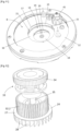
- the fan 24 is a centrifugal radial fan, and comprises an annular impeller 27 comprising a plurality of vanes 28 which are configured such that the air flow generated is evacuated from the cooking volume 5 by flowing through the air exhaust passage 14 and is reintroduced into the cooking volume 5 by flowing through the air intake passage 15.
- the fan 24 is configured to direct the air flow coming from the air exhaust passage 14 radially outwards and towards the air intake passage 15.
- the electric cooking appliance 2 further comprises a drive unit 29 configured to rotate the fan 24.
- the drive unit 29 notably comprises a drive motor 31, visible at the figure 4 , and a motion transmission mechanism 32 which is configured to transmit a rotational motion from the drive motor 31 to the fan 24.
- the motion transmission mechanism 32 may for example comprise a gear 32.1 rotatably coupled to an output shaft of the drive motor 31 and a toothed wheel 32.2 integral in rotation with the fan 24.
- the fan 24 is arranged facing the inner cover 8 and is movable in translation relative to the fixed shutter part 12 in the direction of movement D and between a first fan position in which the fan 24 is located in the internal chamber 9 and is distant of the heater 25, and a second fan position in which the fan 24 is brought closer to the heater 25 and is configured to be located opposite the air intake passage 15.
- the fan 24 is disposed in the internal chamber 9 and set back from the first passage opening 17 when the fan 24 occupies the first fan position, and is located beyond the first passage opening 17 when the fan 24 occupies the second fan position .
- the electric cooking appliance 2 is more particularly configured such that the fan 24 occupies the first fan position when the movable shutter part 13 is in the raised configuration, and such that the fan 24 occupies the second position fan when the movable shutter part 13 is in the lowered configuration.
- the electric cooking appliance 2 comprises a drive mechanism 33 configured to simultaneously move the movable shutter part 13 from the raised configuration to the lowered configuration and the fan 24 from the first fan position to the second fan position, and to simultaneously move the movable shutter portion 13 from the lowered configuration to the raised configuration and the fan 24 from the second fan position to the first fan position.
- the drive mechanism 33 comprises a gripping member 34 which is configured to be manipulated by a user.
- This gripping member 34 is rotatably mounted relative to the cover body 7 around an axis of rotation A which is advantageously substantially parallel to the direction of movement D.
- the drive mechanism 33 also includes a displacement shaft 35 which has a longitudinal axis extending substantially parallel to the direction movement D and which is movable in translation relative to the cover body 7 in the direction of movement D.
- the electric cooking appliance 2 comprises a guide member 36 which is fixed to the cover body 7 and which is configured to guide the displacement shaft 35 in translation relative to the cover body 7.
- the displacement shaft 35 is mechanically connected to the gripping member 34 via a movement transformation mechanism 37 such that rotation of the gripping member 34 in a first direction of rotation causes a translational movement of the movement shaft 35 towards the cooking tank 4, that is to say downwards, when the cover 6 occupies the closed position, and such that a rotation of the The gripping member 34 in a second direction of rotation, opposite the first direction of rotation, causes a translational movement of the displacement shaft 35 opposite the cooking tank 4, that is to say towards the top, when the cover 6 is in the closed position.
- the fan 24 is arranged around the movement shaft 35 and is integral in translation with the movement shaft 35.
- the electric cooking appliance 2 has two bearings 38, such as ball bearings, the inner rings of which are fixed to the displacement shaft 35 and which are configured to support the fan 24 in rotation.
- Each of the bearings 38 can for example be interposed between the toothed wheel 32.2 and the movement shaft 35.
- the electric cooking appliance 2 could comprise a single bearing 38 interposed between the toothed wheel 32.2 and the movement shaft 35.
- the displacement shaft 35 is also mechanically connected to the movable shutter part 13 such that a rotation of the gripping member 34 in the first direction of rotation causes a movement of the movable shutter part 13 towards the lowered configuration and such that rotation of the gripping member 34 in the second direction of rotation causes a movement of the movable shutter part 13 towards the raised configuration.
- the second shutter member 18 is fixed to a lower end portion of the displacement shaft 35, and is configured to be moved by the displacement shaft 35 according to a stroke ascending when the gripping member 34 is rotated in the second direction of rotation, the ascending stroke comprising a first portion of ascending stroke during which the second shutter member 18 is moved in the direction of the first shutter member 16 until 'to come into abutment against a lower face of the first shutter member 16 and a second upward stroke portion during which the first and second shutter members 16, 18 are moved in the direction of the fixed shutter part 12 until until the first and second shutter members 16, 18 reach the first and second shutter positions respectively.
- the second shutter member 18 is also configured to be moved by the displacement shaft 35 in a downward stroke when the gripping member 34 is rotated in the first direction of rotation, the downward stroke comprising a first portion of downward stroke during which the first and second shutter members 16, 18 are moved away from the fixed shutter part 12 until the first shutter member 16 reaches the first release position and a second portion of downward stroke during which the second shutter member 18 is moved away from the first shutter member 16 until the second shutter member 18 reaches the second release position.
- the first downward stroke portion the first shutter member 16 is supported by the second shutter member 18.
- the electric cooking appliance 2 further comprises a discharge valve 41 which is fixed to the cover 6, and for example to the fixed closing part 12, and which can be configured to automatically fluidly connect the cooking volume 5 with the atmosphere when the pressure in the cooking volume 5 exceeds a predetermined threshold value.
- the electric cooking appliance 2 advantageously comprises an additional heating device 42 which is arranged in the housing 3 and which is configured to heat the cooking tank 4 by conduction.
- the additional heating device 42 can for example comprise another resistive heating element, and is advantageously arranged below the bottom wall 4.1 of the cooking tank 4.
- the electric cooking appliance 2 also comprises a control unit 43 which comprises for example a controller, such as a microcontroller, or a processor, such as a microprocessor, and which is configured to control the operation of the cooking appliance.
- a control unit 43 which comprises for example a controller, such as a microcontroller, or a processor, such as a microprocessor, and which is configured to control the operation of the cooking appliance.
- the control unit 43 is more particularly configured to control the operation of the electric cooking appliance 2 according to a pressure cooking mode when simultaneously the cover 6 occupies the closed position and the movable shutter part 13 is in the configuration raised, and according to a hot air cooking mode when simultaneously the cover 6 occupies the closed position and the movable shutter part 13 is in the lowered configuration.
- the user can then control a pressure cooking mode using a user interface provided on the housing 3, and the control unit 43 then controls activation of the additional heating device 42 so as to heat the tank cooking zone 4 and therefore the foods contained in this last.
- the cooking volume 5 being fluidly isolated from the internal chamber 9, the pressure within the cooking tank increases, which makes it possible to cook the food under pressure.
- the cover 6 When a user wishes to cook food contained in the cooking tank 4 in a hot air cooking mode, he moves the cover 6 into the closed position and rotates the gripping member 34 in the first direction of rotation of so as to move the movable shutter part 13 in the lowered configuration.
- the cooking volume 5 is fluidly connected to the internal chamber 9 and to the air exhaust openings 11.
- the user can then control a hot air cooking mode using the user interface provided on the housing 3, and the control unit 43 then controls activation of the drive motor 31 so as to drive in rotation of the fan 24 and generating an air flow within the cooking tank 4 and also an activation of the heating device 25 so as to heat this air flow generated by the fan 24.
- the specific arrangement of the heating device 25 opposite the air intake passage 15 makes it possible to transmit a maximum of calories to the air flow and thus to optimize the hot air cooking obtained with the electric cooking appliance 2 according to the present invention.
- the electric cooking appliance 2 also makes it possible to brown the food contained in the cooking tank.
- the control unit 43 can order, at the end of the hot air cooking cycle, a shutdown of the drive motor 31 while maintaining an electrical supply to the heating device 25, which ensures, due to its position opposite the access opening of the cooking tank 4, a browned cooking of the food.
- the device electric cooking 2 could be devoid of gripping member 34 and could instead comprise an electric motor which would be mechanically connected to the displacement shaft 35 such that a rotation of the electric motor in a first direction of rotation would result in a translational movement of the movement shaft 35 downwards and such that rotation of the electric motor in a second direction of rotation would result in translational movement of the movement shaft 35 upwards.
Landscapes
- Engineering & Computer Science (AREA)
- Food Science & Technology (AREA)
- Chemical & Material Sciences (AREA)
- Combustion & Propulsion (AREA)
- Mechanical Engineering (AREA)
- General Engineering & Computer Science (AREA)
- Baking, Grill, Roasting (AREA)
- Food-Manufacturing Devices (AREA)
- Electric Stoves And Ranges (AREA)
- Cookers (AREA)
Claims (12)
- Elektrisches Kochgerät (2), umfassend:- ein Gehäuse (3), das einen Kochbehälter (4) umfasst, der ein Kochvolumen (5) begrenzt und der eine Zugangsöffnung (4.3), durch die Nahrungsmittel in das Kochvolumen (5) eingeführt werden können, und einen Deckel (6) umfasst, der zwischen einer offenen Position, in der der Deckel (6) einen Zugang zum Kochbehälter (4) gestattet, und einer geschlossenen Position bewegt werden kann, in der der Deckel (6) den Zugang zum Kochbehälter (4) verhindert, wobei der Deckel (6) einen Deckelkörper (7) und einen Innendeckel (8) umfasst, der am Deckelkörper (7) befestigt ist, wobei der Innendeckel (8) einen festen Verschlussteil (12), der am Deckelkörper (7) befestigt ist, und einen beweglichen Verschlussteil (13) umfasst, der in Bezug auf den festen Verschlussteil (12) entlang einer Bewegungsrichtung (D) und zwischen einer angehobenen Konfiguration, in der der feste Verschlussteil (12) und der bewegliche Verschlussteil (13) den Kochbehälter (4) dicht verschließen, wenn sich der Deckel (6) in der geschlossenen Position befindet, und einer abgesenkten Konfiguration bewegt werden kann, wobei, wenn sich der Deckel (6) in der geschlossenen Position befindet, der feste Verschlussteil (12) und der bewegliche Verschlussteil (13) einen Luftauslasskanal (14) zur Außenseite des Kochvolumens (5) und einen Lufteinlasskanal (15) zur Innenseite des Kochvolumens (5) definieren,- einen Antriebsmechanismus (33), der so konfiguriert ist, dass er den beweglichen Verschlussteil (13) zwischen der abgesenkten Konfiguration und der angehobenen Konfiguration bewegt,- einen Lüfter (24), der im Deckel (6) dem Innendeckel (8) zugewandt angeordnet und so konfiguriert ist, dass er einen Luftstrom im Kochvolumen (5) erzeugt, wobei der Lüfter (24) derart konfiguriert ist, dass der erzeugte Luftstrom aus dem Kochvolumen (5) ausgelassen wird, indem er durch den Luftauslasskanal (14) strömt, und wieder in das Kochvolumen (5) eingeführt wird, indem er durch den Lufteinlasskanal (15) strömt, und- eine Heizvorrichtung (25), die am Deckel (6) befestigt ist und die so konfiguriert ist, dass sie den vom Lüfter (24) erzeugten Luftstrom erhitzt,dadurch gekennzeichnet, dass die Heizvorrichtung (25) auf einer Unterseite des Innendeckels (8) angeordnet ist und dem Kochvolumen (5) zugewandt liegt, wenn der Deckel (6) die geschlossene Position einnimmt, und dadurch, dass die Heizvorrichtung (25) in der Nähe des Lufteinlasskanals (15) liegt, wenn sich der bewegliche Verschlussteil (13) in der abgesenkten Konfiguration befindet.
- Elektrisches Kochgerät (2) nach Anspruch 1, wobei die Heizvorrichtung (25) so konfiguriert ist, dass sie mindestens zum Teil dem Lufteinlasskanal (15) zugewandt liegt, wenn sich der bewegliche Verschlussteil (13) in der abgesenkten Konfiguration befindet.
- Elektrisches Kochgerät (2) nach Anspruch 1 oder 2, wobei der Lüfter (24) so konfiguriert ist, dass er, wenn sich der bewegliche Verschlussteil (13) in der abgesenkten Konfiguration befindet, den aus dem Luftauslasskanal (14) kommenden Luftstrom radial in Richtung des Lufteinlasskanals (15) lenkt.
- Elektrisches Kochgerät (2) nach einem der Ansprüche 1 bis 3, wobei der Lüfter (24) in Bezug auf den festen Verschlussteil (12) entlang der Bewegungsrichtung (D) und zwischen einer ersten Lüfterposition, in der der Lüfter (24) von der Heizvorrichtung (25) entfernt ist und sich der bewegliche Verschlussteil (13) in der angehobenen Konfiguration befindet, und einer zweiten Lüfterposition bewegt werden kann, in der der Lüfter (24) der Heizvorrichtung (25) angenähert ist und sich der bewegliche Verschlussteil (13) in der abgesenkten Konfiguration befindet.
- Elektrisches Kochgerät (2) nach einem der Ansprüche 1 bis 4, wobei der Innendeckel (8) und der Deckelkörper (7) eine Innenkammer (9) des Deckels begrenzen, die so konfiguriert ist, dass sie strömungstechnisch mit dem Kochvolumen (5) verbunden ist, wenn sich der bewegliche Verschlussteil (13) in der abgesenkten Konfiguration befindet, und dass sie strömungstechnisch vom Kochvolumen (5) isoliert ist, wenn sich der bewegliche Verschlussteil (13) in der angehobenen Konfiguration befindet.
- Elektrisches Kochgerät (2) nach einem der Ansprüche 1 bis 5, wobei der Lufteinlasskanal (15) insgesamt ringförmig ist und die Heizvorrichtung (25) so konfiguriert ist, dass sie sich mindestens zum Teil um den Lufteinlasskanal (15) herum erstreckt.
- Elektrisches Kochgerät (2) nach einem der Ansprüche 1 bis 6, wobei sich der Lufteinlasskanal (15) und der Luftauslasskanal (14) im Wesentlichen koaxial erstrecken.
- Elektrisches Kochgerät (2) nach einem der Ansprüche 1 bis 7, wobei der bewegliche Verschlussteil (13) umfasst:- ein erstes Verschlussorgan (16), das in Bezug auf den festen Verschlussteil (12) entlang der Bewegungsrichtung (D) bewegt werden kann, wobei das erste Verschlussorgan (16) so konfiguriert ist, dass es eine erste Kanalöffnung (17), die am festen Verschlussteil (12) vorgesehen ist, verschließt, wenn sich der bewegliche Verschlussteil (13) in der angehobenen Konfiguration befindet, und die erste Kanalöffnung (17) freigibt, wenn sich der bewegliche Verschlussteil (13) in der abgesenkten Konfiguration befindet, wobei das erste Verschlussorgan (16) und der feste Verschlussteil (12) so konfiguriert sind, dass sie den Lufteinlasskanal (15) begrenzen, wenn sich der bewegliche Verschlussteil (13) in der abgesenkten Konfiguration befindet, und- ein zweites Verschlussorgan (18), das in Bezug auf das erste Verschlussorgan (16) entlang der Bewegungsrichtung (D) bewegt werden kann, wobei das zweite Verschlussorgan (18) so konfiguriert ist, dass es eine zweite Kanalöffnung (19), die am ersten Verschlussorgan (16) vorgesehen ist, verschließt, wenn sich der bewegliche Verschlussteil (13) in der angehobenen Konfiguration befindet, und die zweite Kanalöffnung (19) freigibt, wenn sich der bewegliche Verschlussteil (13) in der abgesenkten Konfiguration befindet, wobei das erste und das zweite Verschlussorgan (16, 18) so konfiguriert sind, dass sie den Luftauslasskanal (14) begrenzen, wenn sich der bewegliche Verschlussteil (13) in der abgesenkten Konfiguration befindet.
- Elektrisches Kochgerät (2) nach Anspruch 8, wobei das erste und das zweite Verschlussorgan (16, 18) koaxial angeordnet sind.
- Elektrisches Kochgerät (2) nach einem der Ansprüche 1 bis 9, wobei der Innendeckel (8) abnehmbar am Deckelkörper (7) befestigt ist.
- Elektrisches Kochgerät (2) nach einem der Ansprüche 1 bis 10, wobei der Antriebsmechanismus (33) ein Greiforgan (34) umfasst, das so konfiguriert ist, dass es von einem Benutzer gehandhabt werden kann und das in Bezug auf den Deckelkörper (7) um eine Drehachse (A) drehbar angebracht ist, wobei der Antriebsmechanismus (33) derart konfiguriert ist, dass eine Drehung des Greiforgans (34) in eine erste Drehrichtung eine Bewegung des beweglichen Verschlussteils (13) in die abgesenkte Konfiguration bewirkt, und derart, dass eine Drehung des Greiforgans (34) in eine zweite Drehrichtung, die der ersten Drehrichtung entgegengesetzt ist, eine Bewegung des beweglichen Verschlussteils (13) in die angehobene Konfiguration bewirkt.
- Elektrisches Kochgerät (2) nach Anspruch 11, wobei der Antriebsmechanismus (33) eine Bewegungswelle (35) umfasst, die eine Längsachse aufweist, die sich im Wesentlichen parallel zur Bewegungsrichtung (D) erstreckt, wobei die Bewegungswelle (35) in Bezug auf den Deckelkörper (7) entlang der Bewegungsrichtung (D) verschiebebeweglich ist, wobei die Bewegungswelle (35) mechanisch derart mit dem Greiforgan (34) und dem beweglichen Verschlussteil (13) verbunden ist, dass eine Drehung des Greiforgans (34) in die erste Drehrichtung eine Verschiebebewegung der Bewegungswelle (35) nach unten und eine Bewegung des beweglichen Verschlussteils (13) in die abgesenkte Konfiguration bewirkt, und derart, dass eine Drehung des Greiforgans (34) in die zweite Drehrichtung eine Verschiebebewegung der Bewegungswelle (35) nach oben und eine Bewegung des beweglichen Verschlussteils (13) in die angehobene Konfiguration bewirkt.
Applications Claiming Priority (1)
| Application Number | Priority Date | Filing Date | Title |
|---|---|---|---|
| FR2109764A FR3127107B1 (fr) | 2021-09-17 | 2021-09-17 | Appareil de cuisson électrique |
Publications (2)
| Publication Number | Publication Date |
|---|---|
| EP4151132A1 EP4151132A1 (de) | 2023-03-22 |
| EP4151132B1 true EP4151132B1 (de) | 2024-04-24 |
Family
ID=78049456
Family Applications (1)
| Application Number | Title | Priority Date | Filing Date |
|---|---|---|---|
| EP22196004.0A Active EP4151132B1 (de) | 2021-09-17 | 2022-09-15 | Elektrisches kochgerät |
Country Status (6)
| Country | Link |
|---|---|
| US (1) | US20230101591A1 (de) |
| EP (1) | EP4151132B1 (de) |
| JP (1) | JP2023044666A (de) |
| CN (1) | CN115813194A (de) |
| CA (1) | CA3173004C (de) |
| FR (1) | FR3127107B1 (de) |
Family Cites Families (3)
| Publication number | Priority date | Publication date | Assignee | Title |
|---|---|---|---|---|
| FR3082412B1 (fr) * | 2018-06-15 | 2023-01-20 | Seb Sa | Appareil de cuisson de type friteuse a air chaud avec systeme d'obturation de l'extraction de l'air chaud |
| CN209090836U (zh) | 2018-07-27 | 2019-07-12 | 九阳股份有限公司 | 一种压力空气炸锅 |
| US11647861B2 (en) * | 2020-03-30 | 2023-05-16 | Sharkninja Operating Llc | Cooking device and components thereof |
-
2021
- 2021-09-17 FR FR2109764A patent/FR3127107B1/fr active Active
-
2022
- 2022-09-08 CA CA3173004A patent/CA3173004C/fr active Active
- 2022-09-15 EP EP22196004.0A patent/EP4151132B1/de active Active
- 2022-09-15 JP JP2022146777A patent/JP2023044666A/ja active Pending
- 2022-09-16 US US17/946,272 patent/US20230101591A1/en active Pending
- 2022-09-16 CN CN202211127240.9A patent/CN115813194A/zh active Pending
Also Published As
| Publication number | Publication date |
|---|---|
| CN115813194A (zh) | 2023-03-21 |
| EP4151132A1 (de) | 2023-03-22 |
| US20230101591A1 (en) | 2023-03-30 |
| JP2023044666A (ja) | 2023-03-30 |
| CA3173004C (fr) | 2024-05-21 |
| FR3127107B1 (fr) | 2023-09-15 |
| FR3127107A1 (fr) | 2023-03-24 |
| CA3173004A1 (fr) | 2023-03-17 |
Similar Documents
| Publication | Publication Date | Title |
|---|---|---|
| CA2969412C (fr) | Appareil de cuisson a flux d'air | |
| EP3435825B1 (de) | Heissluftkocher | |
| EP2687132B1 (de) | Druckkochgerät mit verbesserter Bedienungsvorrichtung | |
| EP3381338B1 (de) | Gerät zum kochen mithilfe von heissluftstrom mit rührmittel | |
| EP1535553B1 (de) | Druckgargerät mit einzelner Entspannungs- und Verriegelungsvorrichtung | |
| EP2368470B1 (de) | Elektrohaushaltsgerät zur Essenzubereitung, das ein Gehäuse mit einer Arbeitsschüsselhalterung und einem Zerkleinerungswerkzeug zum Einführen in die Schüssel umfasst | |
| EP1671566B1 (de) | Haushaltsgerät zum Bereiten von Nahrungsmitteln zur Herstellung flüssiger Zubereitungen | |
| EP3075295A1 (de) | Elektrohaushaltsgerät zur essenszubereitung, das einen deckel mit einem abzug zum einfüllen von lebensmitteln umfasst | |
| FR2940601A1 (fr) | Appareil de cuisson sous pression a organe de commande du verrouillage/deverrouillage bi-fonctionnel | |
| WO2005053482A1 (fr) | Appareil de cuisson d’aliments sous pression | |
| WO2005053480A1 (fr) | Appareil de cuisson sous pression comportant un moyen de securite a l’ouverture | |
| EP3155940A1 (de) | Haushaltskochgerät | |
| EP1428462A1 (de) | Dampfkochtopf mit reduziertem Platzbedarf | |
| EP1900315A1 (de) | Stabmixgerät, das ein Arbeitswerkzeug in Form einer Archimedischen Schraube umfasst | |
| EP4151132B1 (de) | Elektrisches kochgerät | |
| EP3586689A1 (de) | Schnellkochtopf mit einem anschlag für den deckel | |
| FR3057753B1 (fr) | Appareil electromenager de preparation culinaire comportant une base d’alimentation electrique | |
| FR3051651A1 (fr) | Outil de petrissage pour appareil electromenager de preparation culinaire | |
| EP3424381B1 (de) | Innenbehälter, zubehörteil zur essenszubereitung und elektrohaushaltsgerät zur essenszubereitung, das einen solchen innenbehälter umfasst | |
| FR2822364A1 (fr) | Appareil electromenager de preparation culinaire comportant un outil rotatif et un double dispositif de securite | |
| EP4154776B1 (de) | Küchenmaschinen-untergestell mit einem schwenkbaren sicherheitsverschluss | |
| CN220293479U (zh) | 一种微压空气炸锅 | |
| EP3912525A1 (de) | Kochgerät für lebensmittel, das einen herausnehmbaren kochbehälter umfasst | |
| FR2994524A3 (fr) | Dispositif de cuisson multifonctions | |
| EP3922145A1 (de) | Kochgerät für lebensmittel, das einen herausnehmbaren kochbehälter umfasst |
Legal Events
| Date | Code | Title | Description |
|---|---|---|---|
| PUAI | Public reference made under article 153(3) epc to a published international application that has entered the european phase |
Free format text: ORIGINAL CODE: 0009012 |
|
| STAA | Information on the status of an ep patent application or granted ep patent |
Free format text: STATUS: THE APPLICATION HAS BEEN PUBLISHED |
|
| AK | Designated contracting states |
Kind code of ref document: A1 Designated state(s): AL AT BE BG CH CY CZ DE DK EE ES FI FR GB GR HR HU IE IS IT LI LT LU LV MC MK MT NL NO PL PT RO RS SE SI SK SM TR |
|
| STAA | Information on the status of an ep patent application or granted ep patent |
Free format text: STATUS: REQUEST FOR EXAMINATION WAS MADE |
|
| 17P | Request for examination filed |
Effective date: 20230920 |
|
| RBV | Designated contracting states (corrected) |
Designated state(s): AL AT BE BG CH CY CZ DE DK EE ES FI FR GB GR HR HU IE IS IT LI LT LU LV MC MK MT NL NO PL PT RO RS SE SI SK SM TR |
|
| GRAP | Despatch of communication of intention to grant a patent |
Free format text: ORIGINAL CODE: EPIDOSNIGR1 |
|
| STAA | Information on the status of an ep patent application or granted ep patent |
Free format text: STATUS: GRANT OF PATENT IS INTENDED |
|
| INTG | Intention to grant announced |
Effective date: 20231117 |
|
| GRAS | Grant fee paid |
Free format text: ORIGINAL CODE: EPIDOSNIGR3 |
|
| GRAA | (expected) grant |
Free format text: ORIGINAL CODE: 0009210 |
|
| STAA | Information on the status of an ep patent application or granted ep patent |
Free format text: STATUS: THE PATENT HAS BEEN GRANTED |
|
| AK | Designated contracting states |
Kind code of ref document: B1 Designated state(s): AL AT BE BG CH CY CZ DE DK EE ES FI FR GB GR HR HU IE IS IT LI LT LU LV MC MK MT NL NO PL PT RO RS SE SI SK SM TR |
|
| REG | Reference to a national code |
Ref country code: GB Ref legal event code: FG4D Free format text: NOT ENGLISH |
|
| REG | Reference to a national code |
Ref country code: CH Ref legal event code: EP |
|
| REG | Reference to a national code |
Ref country code: DE Ref legal event code: R096 Ref document number: 602022003046 Country of ref document: DE |
|
| REG | Reference to a national code |
Ref country code: IE Ref legal event code: FG4D Free format text: LANGUAGE OF EP DOCUMENT: FRENCH |