EP4151131A1 - Dampfkochvorrichtung - Google Patents
Dampfkochvorrichtung Download PDFInfo
- Publication number
- EP4151131A1 EP4151131A1 EP21196911.8A EP21196911A EP4151131A1 EP 4151131 A1 EP4151131 A1 EP 4151131A1 EP 21196911 A EP21196911 A EP 21196911A EP 4151131 A1 EP4151131 A1 EP 4151131A1
- Authority
- EP
- European Patent Office
- Prior art keywords
- cooking chamber
- chamber
- steam
- cooking
- heating
- Prior art date
- Legal status (The legal status is an assumption and is not a legal conclusion. Google has not performed a legal analysis and makes no representation as to the accuracy of the status listed.)
- Withdrawn
Links
- 238000010411 cooking Methods 0.000 title claims abstract description 179
- 235000013305 food Nutrition 0.000 claims abstract description 89
- 238000010438 heat treatment Methods 0.000 claims abstract description 68
- 238000000605 extraction Methods 0.000 claims description 30
- 230000000903 blocking effect Effects 0.000 claims description 12
- 230000004888 barrier function Effects 0.000 claims description 8
- 238000000034 method Methods 0.000 abstract description 9
- 230000008569 process Effects 0.000 abstract description 3
- XLYOFNOQVPJJNP-UHFFFAOYSA-N water Substances O XLYOFNOQVPJJNP-UHFFFAOYSA-N 0.000 description 16
- 230000006870 function Effects 0.000 description 11
- 238000013461 design Methods 0.000 description 8
- 241000251468 Actinopterygii Species 0.000 description 5
- 235000019688 fish Nutrition 0.000 description 5
- 230000004048 modification Effects 0.000 description 5
- 238000012986 modification Methods 0.000 description 5
- 230000004075 alteration Effects 0.000 description 4
- 230000006872 improvement Effects 0.000 description 4
- 102000009027 Albumins Human genes 0.000 description 3
- 108010088751 Albumins Proteins 0.000 description 3
- 238000009833 condensation Methods 0.000 description 3
- 230000005494 condensation Effects 0.000 description 3
- 239000007787 solid Substances 0.000 description 3
- 230000008901 benefit Effects 0.000 description 2
- 238000009835 boiling Methods 0.000 description 2
- 238000010586 diagram Methods 0.000 description 2
- 230000007246 mechanism Effects 0.000 description 2
- 235000015097 nutrients Nutrition 0.000 description 2
- 102000004169 proteins and genes Human genes 0.000 description 2
- 108090000623 proteins and genes Proteins 0.000 description 2
- 230000001105 regulatory effect Effects 0.000 description 2
- 238000012546 transfer Methods 0.000 description 2
- 241000972773 Aulopiformes Species 0.000 description 1
- 241000287828 Gallus gallus Species 0.000 description 1
- 230000006978 adaptation Effects 0.000 description 1
- 238000004458 analytical method Methods 0.000 description 1
- 238000013459 approach Methods 0.000 description 1
- 238000003491 array Methods 0.000 description 1
- 230000008859 change Effects 0.000 description 1
- 238000004590 computer program Methods 0.000 description 1
- 230000001276 controlling effect Effects 0.000 description 1
- 230000001351 cycling effect Effects 0.000 description 1
- 230000006378 damage Effects 0.000 description 1
- 230000001419 dependent effect Effects 0.000 description 1
- 230000000694 effects Effects 0.000 description 1
- 239000003779 heat-resistant material Substances 0.000 description 1
- 238000002386 leaching Methods 0.000 description 1
- 239000007788 liquid Substances 0.000 description 1
- 239000002184 metal Substances 0.000 description 1
- 230000003287 optical effect Effects 0.000 description 1
- 229920001296 polysiloxane Polymers 0.000 description 1
- 230000009467 reduction Effects 0.000 description 1
- 235000019515 salmon Nutrition 0.000 description 1
- 229920006395 saturated elastomer Polymers 0.000 description 1
- 238000006748 scratching Methods 0.000 description 1
- 230000002393 scratching effect Effects 0.000 description 1
- 238000000926 separation method Methods 0.000 description 1
- 238000010025 steaming Methods 0.000 description 1
- 238000012360 testing method Methods 0.000 description 1
- 239000006200 vaporizer Substances 0.000 description 1
Images


Classifications
-
- F—MECHANICAL ENGINEERING; LIGHTING; HEATING; WEAPONS; BLASTING
- F24—HEATING; RANGES; VENTILATING
- F24C—DOMESTIC STOVES OR RANGES ; DETAILS OF DOMESTIC STOVES OR RANGES, OF GENERAL APPLICATION
- F24C15/00—Details
- F24C15/32—Arrangements of ducts for hot gases, e.g. in or around baking ovens
- F24C15/322—Arrangements of ducts for hot gases, e.g. in or around baking ovens with forced circulation
- F24C15/327—Arrangements of ducts for hot gases, e.g. in or around baking ovens with forced circulation with air moisturising
-
- A—HUMAN NECESSITIES
- A47—FURNITURE; DOMESTIC ARTICLES OR APPLIANCES; COFFEE MILLS; SPICE MILLS; SUCTION CLEANERS IN GENERAL
- A47J—KITCHEN EQUIPMENT; COFFEE MILLS; SPICE MILLS; APPARATUS FOR MAKING BEVERAGES
- A47J37/00—Baking; Roasting; Grilling; Frying
- A47J37/06—Roasters; Grills; Sandwich grills
- A47J37/0623—Small-size cooking ovens, i.e. defining an at least partially closed cooking cavity
- A47J37/0629—Small-size cooking ovens, i.e. defining an at least partially closed cooking cavity with electric heating elements
- A47J37/0641—Small-size cooking ovens, i.e. defining an at least partially closed cooking cavity with electric heating elements with forced air circulation, e.g. air fryers
Definitions
- This invention relates to a steam cooker, also referred to as a steamer.
- Steam cooking (also referred to as steaming) is commonly known as one of the healthiest cooking methods.
- steam cooking is often preferred over other cooking methods such as boiling, frying and baking because it results in a lower amount of nutrient destruction.
- a traditional steamer comprises a pan for placing over the hob of a cooker, in which water is boiled. Food to be steamed is mounted over the pan in trays having perforated bases.
- Steam cookers are now well known and comprise a steam cooking chamber around which hot air and steam are circulated by a fan.
- the steam cooker is for example a top-loaded device, rather than a more conventional steam oven with a front door.
- Steam is introduced into the cooking chamber, either from an external steam source or else generated internally within the cooking chamber for example by using a vaporizer at the bottom of the cooking chamber.
- a heating chamber adjacent to the cooking chamber comprises a fan and a heater to generate a circulatory flow of hot air and steam. The steam generation may take place in the heating chamber instead of in the cooking chamber.
- the heating chamber is a closed unit next to the main cooking chamber, but it has at least one opening for air intake from the cooking chamber and at least one opening for air delivery into the cooking chamber.
- This invention is based on the recognition that the cooking results in the steam cooker (when used for dry cooking) are worse as a result of the weaker air flow in the steam cooker.
- a steam cooking apparatus comprising:
- the flow redirecting element alters the flow conditions in the cooking chamber to achieve more uniform heating in the region of the food support. This result in increased browning homogeneity (when using the steam cooker in a non-steam mode) for various food types such as fish. It provides an improved heat transfer to the food and an increased local air speed in the vicinity of the food, e.g. above 1 m/s.
- the improved cooking results in reduced protein - albumin leakage for cooking fish, and shorter cooking times for certain food types.
- the introduction of the flow redirecting arrangement enables a low cost improvement to existing products with significant cooking performance improvement.
- the flow redirecting arrangement for example comprises a spoiler.
- This is a projecting fin, for example with a relatively long length and a short projecting depth.
- the spoiler extends inwardly from an inner surface of a front wall of the cooking chamber. Thus, it interrupts the flow of air down the front surface of the cooking chamber, and redirects that flow at least partially towards the food support.
- the spoiler is for example at the level of the bottom of the food support, so that the redirected air flow is directed towards the food.
- the spoiler extends from a front area of the food support. It may project forwardly towards a front wall of the cooking chamber or downwardly towards the bottom.
- a modified food support provides the flow altering function.
- the spoiler for example has a depth to substantially fill a gap between the food support and the cooking chamber.
- the spoiler for example has a length between 0.5 and 0.9 times a width of the food support. Thus, the spoiler does not need to extend the full width of the food support to make a significant difference in air flow conditions.
- the flow redirecting arrangement may comprise a step in an inner surface of a front wall of the cooking chamber.
- the internal shape of the cooking chamber has a step which performs the same function as the spoiler.
- the step is for example at the level of the bottom of the food support, so that the redirected air flow is towards the food.
- the apparatus may further comprise upright fins at opposite ends of the flow redirecting element (spoiler or step). These provide further directing of the flow towards the food support, by forming a partially enclosed channel of air.
- the apparatus may further comprise a fan in the heating chamber, wherein the vent arrangement comprises an extraction vent between the cooking chamber and the heating chamber at the location of the fan, for drawing air from the cooking chamber to the heating chamber.
- the apparatus further comprises a barrier ring around the extraction vent. This prevents air entry to the extraction vent from steep angles, and thereby creates a further alteration to the flow conditions, which has again been found to result in more uniform heating in the region of the food support.
- the apparatus may further comprise a blocking element spaced over the extraction vent. This prevents air entry to the extraction vent directly from in front, and again thereby creates a further alteration to the flow conditions. This has also been found to result in more uniform heating in the region of the food support.
- the blocking element may comprise a disc (i.e. a solid closed shape) or a plate with a central opening.
- the vent arrangement for example also comprises a delivery vent between the heating chamber and the cooking chamber, for delivering heated air to the cooking chamber, and a fin arrangement is provided at the delivery vent.
- a delivery vent between the heating chamber and the cooking chamber, for delivering heated air to the cooking chamber
- a fin arrangement is provided at the delivery vent.
- the invention also provides a steam cooking apparatus, comprising:
- This aspect relates in particular to the use of a ring around extraction vent as also discussed above.
- This design may be combined any combination of the other features explained above, namely the flow redirecting element at the front of the cooking chamber (spoiler or stepped cooking chamber), the optional fins at the ends of the flow redirecting element, the blocking element over the extraction vent and the fins at the delivery vent.
- the invention provides a steam cooking apparatus with a cooking chamber, a steam generator for generating steam to be provided to the cooking chamber and a heating system.
- a food support is for mounting in the cooking chamber.
- a flow redirecting arrangement is provided at the front of the cooking chamber for redirecting flow from the front of the cooking chamber away from the stream generator and towards the food support. This improves the uniformity of the cooking process, particularly when the steam cooking apparatus is used in a non-steam mode, and uniform browning of food is desired.
- Figure 1 shows a known cooking apparatus 10, in particular as disclosed in WO 2020/148187 .
- the cooking apparatus comprises a cooking chamber 12 (i.e. a food chamber in which food to be cooked is placed) in which a food support (basket) 14 is mounted.
- the cooking chamber has a viewing window 13 which may also be the openable lid of the apparatus.
- Food 15 to be cooked is placed on the food support which then places the food near the center of the cooking chamber.
- the food support has air permeable side walls and optionally an air permeable base so that air and steam can circulate through the support to the food.
- a heating arrangement which in this example comprises a first heater 16 for generating steam and a second heater 18 for heating air laden with steam.
- the first heater is used to generate steam (shown as arrow 17) from water which is delivered from a water reservoir 20 by a dosing system 22.
- the dosing system provides water to a feed arrangement 23 which delivers water to a surface of the first heater 16 to generate steam.
- the dosing system may deliver a constant flow of water during cooking or a regularly pulsed delivery of water (so needing no feedback control), but it could also be controlled dynamically during cooking using feedback from a humidity sensor.
- a circulation system is provided in the form of a fan 24 and motor 26.
- the circulation system circulates the steam generated by the first heater 16 around the cooking chamber.
- the second heater 18 is along the circulation path and thereby further heats the steam to create a high temperature dry steam environment.
- the circulation system thus moves the saturated air inside the chamber to the food to increase convection and also assists in producing a homogeneous temperature field of all parts inside the cooking chamber, including the viewing window. This is to avoid condensation.
- the apparatus is controlled by a controller 28, which controls the heating arrangement 16, 18 and optionally also the dosing system 22.
- the controller receives temperature information from a temperature sensor 30.
- the temperature of interest is the temperature at the center of the cooking chamber, where the food is located.
- the temperature sensor which may be a negative temperature coefficient (NTC) temperature sensor, may be located anywhere in the cooking chamber, with a known correlation between the temperature at the sensor location and the temperature in the middle of the chamber.
- NTC negative temperature coefficient
- the temperature is for example regulated by switching on and off the second heater 18 of the heating arrangement by the controller.
- the temperature of the first heater, for steam generation, is regulated by a thermostat again by cycling on and off.
- the cooking chamber is vented to the ambient surroundings by vents 32. Thus, the cooking chamber remains at substantially atmospheric pressure during use.
- the controller 28 controls the heating arrangement to heat water from the water reservoir to create steam using the first heater 16, and to further heat the steam to create heated steam at a temperature around 100 degrees.
- the second heater may further heat the steam for example to 120 degrees Celsius, or in the range 110 to 120 degrees Celsius. This approach is explained in WO 2020/0099339 . Higher temperatures up to 200 degrees Celsius could be considered as well.
- the circulation system circulates the heated steam around the cooking chamber.
- the vent or vents of the cooking chamber maintain the pressure at ambient pressure, and thus steam can escape when the maximum possible absolute humidity is reached (for the particular operating temperature), which would otherwise result in an increase in pressure.
- the release mechanism provided by the vent or vents means that the steam delivery rate does not need to be controlled, and instead there can be a preset water delivery rate to the first heater 16.
- the controller may for example implement a control sequence which determines particular points of time when steam generation starts and/or ends. By way of example, a time-delayed start may be used for steam generation.
- the device is for example in a waiting mode for certain time e.g. 2 minutes from the start or else waiting until the cooking chamber temperature reaches 100 degrees Celsius. Water is then added to the first water heater 16. This pre-heating improves the avoidance of condensation at the window of the transparent lid as discussed below.
- the device also has an operation mode without any steam generation.
- This invention is in particular aimed at improving the cooking results when used in the operation mode without steam generation, as discussed further below.
- the cooking chamber 12 comprises a base 40, a rear wall area 42, first and second opposing side wall areas and a front wall area 44. These together define a closed chamber.
- the rear wall area 42 defines a separation wall which separates the cooking chamber 12 from a heating chamber 45 in which (at least) the fan blades 24 and second heater 18 are housed.
- the motor 26, water reservoir 20, dosing system 22, and controller 28 are in a further chamber which is isolated from the heating chamber (i.e. there is no gas or liquid passage between them). However, there may be different components in the different chambers.
- Figure 2 shows the cooking chamber opened up to show the rear wall area and the first and second side wall areas 46, 48 to show one example of vent arrangement.
- the circulation system draws air out of the cooking chamber through an extraction vent 50 in the rear wall area. This vent leads to the fan blades.
- a delivery vent arrangement for delivering air (and steam) comprises a first delivery vent 52 at a top region of the rear wall area above the extraction vent 50. It may extend across at least half of the width of the rear wall area, such as across more than 60%, 70% or 80% of that width.
- a second delivery vent 54 is at a top region of the first side wall area 46 and a third delivery vent 56 is at a top region of the second side wall area 48.
- vents and fan It is possible through design of the vents and fan to control the circulation of air and steam within the cooking chamber in a reliable and repeatable way.
- wall "area" is used because the shape (from above) may not be a polygon, but instead may be a more curved shaped thus not having precisely defined sides, front and back.
- shape (from above) is generally square or rectangular, so that corresponding front, back and sides may be readily identified. However, this does not imply that other shapes are not possible. Even a circle may be considered to have sides, a front and back by dividing it into quadrants.
- vents shown enable a flow of the delivered air to pass over the full area of the underside of the lid 13.
- the viewing window area of the lid 13 has increased heat losses compared to an insulated wall so it is desirable for the window to be exposed to the flow created by the circulation system to maintain the viewing window above the dew point.
- the steam cooking apparatus is as described in WO 2020/148187 .
- the invention relates to control of the air flow particularly for the no steam cooking mode.
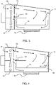
- FIG. 3 shows a simplified diagram of the cooking apparatus including the food support, and showing the flow paths.
- the main circulatory flow is shown as 70 from the delivery vent 52 to the extraction vent 50.
- the flow largely follows the internal surface of the cooking chamber, down to the bottom of the cooking chamber.
- Figure 3 also shows that the lid is inclined downwardly from the rear wall to the front wall. This further assists in preventing condensation of steam at the transparent section of the lid via heating.
- Figure 4 shows a first example of a modification to improve the air flow conditions in the food chamber.
- the apparatus comprises a flow redirecting arrangement 60 at the front of the cooking chamber for redirecting flow from the front of the cooking chamber away from the stream generator and towards the food support 14.
- the change in flow paths is schematically shown, and can be seen by comparing Figure 4 with Figure 3 .
- the flow redirecting element 60 alters the flow conditions in the cooking chamber to achieve more uniform heating in the region of the food support.
- the improved cooking process results in reduced protein - albumin leakage for cooking fish, and shorter cooking times for certain food.
- the introduction of the flow redirecting arrangement enables a low cost improvement to existing products with significant cooking performance improvement.
- the flow redirecting arrangement 60 comprises a spoiler extending widthwise across the front wall of the cooking chamber, and projecting back towards the interior volume of the cooking chamber.
- the spoiler is a projecting fin, for example with a relatively long length and a short projecting depth.
- the spoiler is for example at the level of the bottom of the food support, so that the redirected air flow is towards the food. However, it may be slightly raised above the bottom of the food support.
- the spoiler projects forwards from the food support (basket) 14. It creates the same flow barrier, essentially closing the gap between the food support and the front wall of the cooking chamber, thereby disturbing a flow around the inside wall of the cooking chamber.
- the spoiler could be a separate part which could be inserted as accessory or as attachment to the chamber or to the food support.
- a system could be used for automatically moving or removing (e.g. swing in and out) the spoiler when a specific cooking method requires specific flow conditions.
- Figure 5 shows the spoiler from above, looking down into the cooking chamber, and for a version where it projects forwardly from a front face of the food support 14.
- the spoiler has a length which may correspond to the full width of the food support, but the length may be less than the width of the food support as shown in Figure 5 .
- the food support has rounded corners, and the spoiler extends only adjacent the central straight section of the front of the food support.
- the length is for example between 0.5 and 0.9 times the width of the food support 14.
- the spoiler or several individual spoilers could be mounted at several position along the width of the food support.
- Different fans or air intake vent concepts may need different spoiler shapes, such as symmetric or asymmetric designs, to homogenize the flow.
- the spoiler has a depth (i.e. the distance by which it extends outwardly from its supporting structure) to substantially fill the gap between the food support and the cooking chamber.
- the spoiler has a depth of at least 5mm, i.e. it projects from an underlying generally planar surface by at least 5mm, for example at least 10mm.
- the remaining gap between the outer projecting edge of the spoiler and the adjacent structure is for example less than 10mm, for example lass than 5mm for example less than 3mm,
- the adjacent structure is the food support. If the spoiler projects from the food support (as in Figure 5 ), the adjacent structure may be the front wall of the cooking chamber ( Figure 5 ) or it may the bottom of the cooking chamber ( Figure 7 ).
- Figure 6 shows a further refinement in which the spoiler 60 has upright fins 62 at opposite ends of the spoiler. These provide further directing of the flow towards the food support, by forming a partially enclosed channel of air. There may be additional fins along the length of the spoiler.
- the fins for example have a height of around 30mm.
- the fin depth corresponds to the gap size between the food support and the cooking chamber, for example around 15mm.
- the depth is preferably a small margin less than the space, to prevent scratching.
- the spoiler projects forwardly from the food support towards a front wall of the cooking chamber.
- Figure 7 shows an alternative in which the spoiler 60 extends downwardly towards the bottom.
- the spoiler may then be formed as part of the design of the support feet for the food support or formed as a bent over edge of the food support. Equivalently, the spoiler may project up from the bottom of the cooking chamber rather than down from the food support.
- the spoiler does not block the passage of air over the steam heater 16 - there is for example an air path around the ends of the spoiler.
- the flow redirecting arrangement may comprise a step 70 in an inner surface of a front wall of the cooking chamber.
- the internal shape of the cooking chamber has a step which performs the same function as the spoiler.
- the step is again at the level of the bottom of the food support, so that the redirected air flow is towards the food.
- the step can have the same depth as the spoiler as discussed above.
- the step may also perform part of the function of holding the food support.
- the step does not need to cover the whole cooking chamber width, but may be placed only at a central area, as for the spoiler as described above.
- Airflow and airspeed analysis has shown that the airspeed in the center of the food support in the conventional design is around 0.4 m/s. Cooking tests have shown that this is the main reason for less food browning and increased albumin leakage e.g. from fish.
- the flow redirecting arrangement has been found to increase the airspeed significantly and give improved cooking end-results, especially browning.
- the central airspeed has been found to increase to 1.7m/s. Cooking speed is also improved for some food types such as salmon and chicken, with a 10% reduction in cooking time recorded.
- the spoiler may be attached to the food support or the cooking chamber as explained above. It may be made of metal, silicone or other heat resistant material.
- the food support is preferably designed to fit in the cooking chamber with only one orientation, to prevent a wrongly positioned food support (e.g. with the spoiler at the air inlet side).
- the measures above relate to controlling the air flow conditions locally at the front of the food container.
- Figure 9 shows a blocking element 90 spaced over the extraction vent 50. This prevents air entry to the extraction vent directly from in front, and again thereby creates a further alteration to the flow conditions. This has also been found to result in more uniform heating in the region of the food support.
- the blocking element 90 may comprise a solid disc as shown in Figure 9 or or a plate with a central opening as shown in Figure 10 .
- the outer diameter of the plate is then larger than the diameter of the extraction vent.
- the blocking element is for example spaced from the extraction vent by a spacing of e.g. 10mm to 15mm.
- the blocking element is a disc which is smaller than the size of the extraction vent, so that it only covers a central area of the extraction vent. It may instead be the same size as the extraction vent or indeed larger.
- the extraction vent for example has a diameter of around 80mm, and the blocking element may have a diameter of 30 to 60mm or 60 to 90mm or 90 to 120mm.
- Figure 11 shows a modification with a barrier ring 100 around the extraction vent 50. This prevents air entry to the extraction vent from steep angles, and thereby creates a further alteration to the flow conditions, which has again been found to result in more uniform heating in the region of the food support.
- the barrier ring for example extends forwardly from the rear wall by around 10mm for example by 8mm to 15mm.
- Flow guiding parts may also be provided at the delivery vent 52 between the heating chamber and the cooking chamber.
- Figure 12 shows a fin arrangement comprising a line of vertical fins 110 provided at the delivery vent. The flow conditions from the heating chamber to the cooking chamber can thereby be controlled to provide more uniform heating.
- the examples above make use of a heater for generating steam within the cooking chamber,
- the steam generation may instead take place in the heating chamber, or the steam generation may be external to the main body of the steam cooker, with steam delivered by a delivery tube.
- the examples above also show a fan in the heating chamber.
- the fan may instead be in the cooking chamber, or alternative methods may be used for generating the desired circulatory flow so that the heater steam laden air circulates around the cooking chamber.
- the examples above have the support (and/or pot) sitting on a base.
- the support may be received directly in the cooking chamber.
- the support may for example be mounted to sidewalls of the cooking chamber or it may hang down from an upper edge of the cooking chamber or the lid, with hooks.
- the base does not need to sit on the base of the cooking chamber. It may instead again hang down from the top of the cooking chamber or lid, or be supported be the side walls.
- controllers can be implemented in numerous ways, with software and/or hardware, to perform the various functions required.
- a processor is one example of a controller which employs one or more microprocessors that may be programmed using software (e.g., microcode) to perform the required functions.
- a controller may however be implemented with or without employing a processor, and also may be implemented as a combination of dedicated hardware to perform some functions and a processor (e.g., one or more programmed microprocessors and associated circuitry) to perform other functions.
- controller components that may be employed in various embodiments of the present disclosure include, but are not limited to, conventional microprocessors, application specific integrated circuits (ASICs), and field-programmable gate arrays (FPGAs).
- ASICs application specific integrated circuits
- FPGAs field-programmable gate arrays
- a processor or controller may be associated with one or more storage media such as volatile and non-volatile computer memory such as RAM, PROM, EPROM, and EEPROM.
- the storage media may be encoded with one or more programs that, when executed on one or more processors and/or controllers, perform the required functions.
- Various storage media may be fixed within a processor or controller or may be transportable, such that the one or more programs stored thereon can be loaded into a processor or controller.
- a computer program may be stored/distributed on a suitable medium, such as an optical storage medium or a solid-state medium supplied together with or as part of other hardware, but may also be distributed in other forms, such as via the Internet or other wired or wireless telecommunication systems. Any reference signs in the claims should not be construed as limiting the scope.
Priority Applications (4)
| Application Number | Priority Date | Filing Date | Title |
|---|---|---|---|
| EP21196911.8A EP4151131A1 (de) | 2021-09-15 | 2021-09-15 | Dampfkochvorrichtung |
| PCT/EP2022/074384 WO2023041346A1 (en) | 2021-09-15 | 2022-09-01 | Steam cooking apparatus |
| CN202211116812.3A CN115804523A (zh) | 2021-09-15 | 2022-09-14 | 蒸汽烹饪装置 |
| CN202222431110.6U CN218773723U (zh) | 2021-09-15 | 2022-09-14 | 蒸汽烹饪装置 |
Applications Claiming Priority (1)
| Application Number | Priority Date | Filing Date | Title |
|---|---|---|---|
| EP21196911.8A EP4151131A1 (de) | 2021-09-15 | 2021-09-15 | Dampfkochvorrichtung |
Publications (1)
| Publication Number | Publication Date |
|---|---|
| EP4151131A1 true EP4151131A1 (de) | 2023-03-22 |
Family
ID=77774822
Family Applications (1)
| Application Number | Title | Priority Date | Filing Date |
|---|---|---|---|
| EP21196911.8A Withdrawn EP4151131A1 (de) | 2021-09-15 | 2021-09-15 | Dampfkochvorrichtung |
Country Status (3)
| Country | Link |
|---|---|
| EP (1) | EP4151131A1 (de) |
| CN (2) | CN115804523A (de) |
| WO (1) | WO2023041346A1 (de) |
Citations (6)
| Publication number | Priority date | Publication date | Assignee | Title |
|---|---|---|---|---|
| FR2871042A1 (fr) * | 2004-06-08 | 2005-12-09 | Seb Sa | Friteuse a enduction automatique de matiere grasse |
| EP2083223A1 (de) * | 2006-11-02 | 2009-07-29 | Sharp Kabushiki Kaisha | Vorrichtung zum verdünnen von abgeführtem dampf und kochvorrichtung damit |
| WO2017097790A1 (en) * | 2015-12-07 | 2017-06-15 | Koninklijke Philips N.V. | Shield for air-based fryer apparatus |
| US20180035698A1 (en) * | 2016-08-02 | 2018-02-08 | Spectrum Brands, Inc. | Air frying systems and methods |
| WO2020099339A1 (en) | 2018-11-15 | 2020-05-22 | Koninklijke Philips N.V. | Steam cooking apparatus and method |
| WO2020148187A1 (en) | 2019-01-14 | 2020-07-23 | Koninklijke Philips N.V. | Steam cooking apparatus |
-
2021
- 2021-09-15 EP EP21196911.8A patent/EP4151131A1/de not_active Withdrawn
-
2022
- 2022-09-01 WO PCT/EP2022/074384 patent/WO2023041346A1/en unknown
- 2022-09-14 CN CN202211116812.3A patent/CN115804523A/zh active Pending
- 2022-09-14 CN CN202222431110.6U patent/CN218773723U/zh active Active
Patent Citations (6)
| Publication number | Priority date | Publication date | Assignee | Title |
|---|---|---|---|---|
| FR2871042A1 (fr) * | 2004-06-08 | 2005-12-09 | Seb Sa | Friteuse a enduction automatique de matiere grasse |
| EP2083223A1 (de) * | 2006-11-02 | 2009-07-29 | Sharp Kabushiki Kaisha | Vorrichtung zum verdünnen von abgeführtem dampf und kochvorrichtung damit |
| WO2017097790A1 (en) * | 2015-12-07 | 2017-06-15 | Koninklijke Philips N.V. | Shield for air-based fryer apparatus |
| US20180035698A1 (en) * | 2016-08-02 | 2018-02-08 | Spectrum Brands, Inc. | Air frying systems and methods |
| WO2020099339A1 (en) | 2018-11-15 | 2020-05-22 | Koninklijke Philips N.V. | Steam cooking apparatus and method |
| WO2020148187A1 (en) | 2019-01-14 | 2020-07-23 | Koninklijke Philips N.V. | Steam cooking apparatus |
Also Published As
| Publication number | Publication date |
|---|---|
| WO2023041346A1 (en) | 2023-03-23 |
| CN218773723U (zh) | 2023-03-31 |
| CN115804523A (zh) | 2023-03-17 |
Similar Documents
| Publication | Publication Date | Title |
|---|---|---|
| EP4082405A1 (de) | Dampfkochvorrichtung | |
| EP3653089A1 (de) | Dampfgarvorrichtung und -verfahren | |
| CN108471907A (zh) | 用于利用热空气和引入到其中的流体制备食物原料的装置和方法 | |
| EP1867264A1 (de) | Gerät zur Behandlung von Lebensmitteln | |
| KR20040096037A (ko) | 가열조리기 | |
| CN218635796U (zh) | 蒸汽烹饪装置 | |
| EP4151131A1 (de) | Dampfkochvorrichtung | |
| EP4018885A1 (de) | Dampfkochvorrichtung | |
| EP4036481A1 (de) | Dampfkochvorrichtung | |
| US20240074607A1 (en) | Steam cooking apparatus | |
| EP4019852A1 (de) | Dampfkochvorrichtung | |
| CN217510318U (zh) | 烹饪设备 | |
| CN217408571U (zh) | 用于烹饪食物的烹饪系统 | |
| EP2181940A1 (de) | Schale für Lebensmittel |
Legal Events
| Date | Code | Title | Description |
|---|---|---|---|
| PUAI | Public reference made under article 153(3) epc to a published international application that has entered the european phase |
Free format text: ORIGINAL CODE: 0009012 |
|
| STAA | Information on the status of an ep patent application or granted ep patent |
Free format text: STATUS: THE APPLICATION HAS BEEN PUBLISHED |
|
| AK | Designated contracting states |
Kind code of ref document: A1 Designated state(s): AL AT BE BG CH CY CZ DE DK EE ES FI FR GB GR HR HU IE IS IT LI LT LU LV MC MK MT NL NO PL PT RO RS SE SI SK SM TR |
|
| RAP3 | Party data changed (applicant data changed or rights of an application transferred) |
Owner name: VERSUNI HOLDING B.V. |
|
| STAA | Information on the status of an ep patent application or granted ep patent |
Free format text: STATUS: THE APPLICATION IS DEEMED TO BE WITHDRAWN |
|
| 18D | Application deemed to be withdrawn |
Effective date: 20230923 |