EP4150326B1 - Spektralanalyse einer probe - Google Patents
Spektralanalyse einer probe Download PDFInfo
- Publication number
- EP4150326B1 EP4150326B1 EP21709796.3A EP21709796A EP4150326B1 EP 4150326 B1 EP4150326 B1 EP 4150326B1 EP 21709796 A EP21709796 A EP 21709796A EP 4150326 B1 EP4150326 B1 EP 4150326B1
- Authority
- EP
- European Patent Office
- Prior art keywords
- sample
- light
- optics
- collector
- spectrometer
- Prior art date
- Legal status (The legal status is an assumption and is not a legal conclusion. Google has not performed a legal analysis and makes no representation as to the accuracy of the status listed.)
- Active
Links
Images


Classifications
-
- A—HUMAN NECESSITIES
- A61—MEDICAL OR VETERINARY SCIENCE; HYGIENE
- A61B—DIAGNOSIS; SURGERY; IDENTIFICATION
- A61B5/00—Measuring for diagnostic purposes; Identification of persons
- A61B5/0059—Measuring for diagnostic purposes; Identification of persons using light, e.g. diagnosis by transillumination, diascopy, fluorescence
- A61B5/0075—Measuring for diagnostic purposes; Identification of persons using light, e.g. diagnosis by transillumination, diascopy, fluorescence by spectroscopy, i.e. measuring spectra, e.g. Raman spectroscopy, infrared absorption spectroscopy
-
- G—PHYSICS
- G01—MEASURING; TESTING
- G01J—MEASUREMENT OF INTENSITY, VELOCITY, SPECTRAL CONTENT, POLARISATION, PHASE OR PULSE CHARACTERISTICS OF INFRARED, VISIBLE OR ULTRAVIOLET LIGHT; COLORIMETRY; RADIATION PYROMETRY
- G01J3/00—Spectrometry; Spectrophotometry; Monochromators; Measuring colours
- G01J3/02—Details
- G01J3/0205—Optical elements not provided otherwise, e.g. optical manifolds, diffusers, windows
- G01J3/0208—Optical elements not provided otherwise, e.g. optical manifolds, diffusers, windows using focussing or collimating elements, e.g. lenses or mirrors; performing aberration correction
-
- G—PHYSICS
- G01—MEASURING; TESTING
- G01J—MEASUREMENT OF INTENSITY, VELOCITY, SPECTRAL CONTENT, POLARISATION, PHASE OR PULSE CHARACTERISTICS OF INFRARED, VISIBLE OR ULTRAVIOLET LIGHT; COLORIMETRY; RADIATION PYROMETRY
- G01J3/00—Spectrometry; Spectrophotometry; Monochromators; Measuring colours
- G01J3/02—Details
- G01J3/0205—Optical elements not provided otherwise, e.g. optical manifolds, diffusers, windows
- G01J3/0216—Optical elements not provided otherwise, e.g. optical manifolds, diffusers, windows using light concentrators or collectors or condensers
-
- G—PHYSICS
- G01—MEASURING; TESTING
- G01J—MEASUREMENT OF INTENSITY, VELOCITY, SPECTRAL CONTENT, POLARISATION, PHASE OR PULSE CHARACTERISTICS OF INFRARED, VISIBLE OR ULTRAVIOLET LIGHT; COLORIMETRY; RADIATION PYROMETRY
- G01J3/00—Spectrometry; Spectrophotometry; Monochromators; Measuring colours
- G01J3/02—Details
- G01J3/0205—Optical elements not provided otherwise, e.g. optical manifolds, diffusers, windows
- G01J3/0218—Optical elements not provided otherwise, e.g. optical manifolds, diffusers, windows using optical fibers
- G01J3/0221—Optical elements not provided otherwise, e.g. optical manifolds, diffusers, windows using optical fibers the fibers defining an entry slit
-
- G—PHYSICS
- G01—MEASURING; TESTING
- G01J—MEASUREMENT OF INTENSITY, VELOCITY, SPECTRAL CONTENT, POLARISATION, PHASE OR PULSE CHARACTERISTICS OF INFRARED, VISIBLE OR ULTRAVIOLET LIGHT; COLORIMETRY; RADIATION PYROMETRY
- G01J3/00—Spectrometry; Spectrophotometry; Monochromators; Measuring colours
- G01J3/02—Details
- G01J3/0205—Optical elements not provided otherwise, e.g. optical manifolds, diffusers, windows
- G01J3/0229—Optical elements not provided otherwise, e.g. optical manifolds, diffusers, windows using masks, aperture plates, spatial light modulators or spatial filters, e.g. reflective filters
-
- G—PHYSICS
- G01—MEASURING; TESTING
- G01J—MEASUREMENT OF INTENSITY, VELOCITY, SPECTRAL CONTENT, POLARISATION, PHASE OR PULSE CHARACTERISTICS OF INFRARED, VISIBLE OR ULTRAVIOLET LIGHT; COLORIMETRY; RADIATION PYROMETRY
- G01J3/00—Spectrometry; Spectrophotometry; Monochromators; Measuring colours
- G01J3/02—Details
- G01J3/0289—Field-of-view determination; Aiming or pointing of a spectrometer; Adjusting alignment; Encoding angular position; Size of measurement area; Position tracking
-
- G—PHYSICS
- G01—MEASURING; TESTING
- G01J—MEASUREMENT OF INTENSITY, VELOCITY, SPECTRAL CONTENT, POLARISATION, PHASE OR PULSE CHARACTERISTICS OF INFRARED, VISIBLE OR ULTRAVIOLET LIGHT; COLORIMETRY; RADIATION PYROMETRY
- G01J3/00—Spectrometry; Spectrophotometry; Monochromators; Measuring colours
- G01J3/02—Details
- G01J3/0297—Constructional arrangements for removing other types of optical noise or for performing calibration
-
- G—PHYSICS
- G01—MEASURING; TESTING
- G01J—MEASUREMENT OF INTENSITY, VELOCITY, SPECTRAL CONTENT, POLARISATION, PHASE OR PULSE CHARACTERISTICS OF INFRARED, VISIBLE OR ULTRAVIOLET LIGHT; COLORIMETRY; RADIATION PYROMETRY
- G01J3/00—Spectrometry; Spectrophotometry; Monochromators; Measuring colours
- G01J3/28—Investigating the spectrum
- G01J3/44—Raman spectrometry; Scattering spectrometry ; Fluorescence spectrometry
- G01J3/4412—Scattering spectrometry
-
- G—PHYSICS
- G01—MEASURING; TESTING
- G01J—MEASUREMENT OF INTENSITY, VELOCITY, SPECTRAL CONTENT, POLARISATION, PHASE OR PULSE CHARACTERISTICS OF INFRARED, VISIBLE OR ULTRAVIOLET LIGHT; COLORIMETRY; RADIATION PYROMETRY
- G01J3/00—Spectrometry; Spectrophotometry; Monochromators; Measuring colours
- G01J3/28—Investigating the spectrum
- G01J3/45—Interferometric spectrometry
-
- G—PHYSICS
- G01—MEASURING; TESTING
- G01N—INVESTIGATING OR ANALYSING MATERIALS BY DETERMINING THEIR CHEMICAL OR PHYSICAL PROPERTIES
- G01N21/00—Investigating or analysing materials by the use of optical means, i.e. using sub-millimetre waves, infrared, visible or ultraviolet light
- G01N21/17—Systems in which incident light is modified in accordance with the properties of the material investigated
- G01N21/25—Colour; Spectral properties, i.e. comparison of effect of material on the light at two or more different wavelengths or wavelength bands
- G01N21/31—Investigating relative effect of material at wavelengths characteristic of specific elements or molecules, e.g. atomic absorption spectrometry
-
- G—PHYSICS
- G01—MEASURING; TESTING
- G01N—INVESTIGATING OR ANALYSING MATERIALS BY DETERMINING THEIR CHEMICAL OR PHYSICAL PROPERTIES
- G01N21/00—Investigating or analysing materials by the use of optical means, i.e. using sub-millimetre waves, infrared, visible or ultraviolet light
- G01N21/17—Systems in which incident light is modified in accordance with the properties of the material investigated
- G01N21/47—Scattering, i.e. diffuse reflection
- G01N21/4738—Diffuse reflection, e.g. also for testing fluids, fibrous materials
- G01N21/474—Details of optical heads therefor, e.g. using optical fibres
-
- G—PHYSICS
- G01—MEASURING; TESTING
- G01N—INVESTIGATING OR ANALYSING MATERIALS BY DETERMINING THEIR CHEMICAL OR PHYSICAL PROPERTIES
- G01N21/00—Investigating or analysing materials by the use of optical means, i.e. using sub-millimetre waves, infrared, visible or ultraviolet light
- G01N21/84—Systems specially adapted for particular applications
- G01N21/88—Investigating the presence of flaws or contamination
- G01N21/95—Investigating the presence of flaws or contamination characterised by the material or shape of the object to be examined
- G01N21/9508—Capsules; Tablets
-
- G—PHYSICS
- G01—MEASURING; TESTING
- G01N—INVESTIGATING OR ANALYSING MATERIALS BY DETERMINING THEIR CHEMICAL OR PHYSICAL PROPERTIES
- G01N33/00—Investigating or analysing materials by specific methods not covered by groups G01N1/00 - G01N31/00
- G01N33/15—Medicinal preparations ; Physical properties thereof, e.g. dissolubility
-
- G—PHYSICS
- G01—MEASURING; TESTING
- G01J—MEASUREMENT OF INTENSITY, VELOCITY, SPECTRAL CONTENT, POLARISATION, PHASE OR PULSE CHARACTERISTICS OF INFRARED, VISIBLE OR ULTRAVIOLET LIGHT; COLORIMETRY; RADIATION PYROMETRY
- G01J3/00—Spectrometry; Spectrophotometry; Monochromators; Measuring colours
- G01J3/28—Investigating the spectrum
- G01J3/45—Interferometric spectrometry
- G01J3/453—Interferometric spectrometry by correlation of the amplitudes
- G01J2003/4538—Special processing
-
- G—PHYSICS
- G01—MEASURING; TESTING
- G01N—INVESTIGATING OR ANALYSING MATERIALS BY DETERMINING THEIR CHEMICAL OR PHYSICAL PROPERTIES
- G01N21/00—Investigating or analysing materials by the use of optical means, i.e. using sub-millimetre waves, infrared, visible or ultraviolet light
- G01N21/17—Systems in which incident light is modified in accordance with the properties of the material investigated
- G01N21/47—Scattering, i.e. diffuse reflection
- G01N2021/4735—Solid samples, e.g. paper, glass
-
- G—PHYSICS
- G01—MEASURING; TESTING
- G01N—INVESTIGATING OR ANALYSING MATERIALS BY DETERMINING THEIR CHEMICAL OR PHYSICAL PROPERTIES
- G01N21/00—Investigating or analysing materials by the use of optical means, i.e. using sub-millimetre waves, infrared, visible or ultraviolet light
- G01N21/17—Systems in which incident light is modified in accordance with the properties of the material investigated
- G01N21/47—Scattering, i.e. diffuse reflection
- G01N21/4738—Diffuse reflection, e.g. also for testing fluids, fibrous materials
- G01N21/474—Details of optical heads therefor, e.g. using optical fibres
- G01N2021/4742—Details of optical heads therefor, e.g. using optical fibres comprising optical fibres
- G01N2021/4745—Fused bundle, i.e. for backscatter
-
- G—PHYSICS
- G01—MEASURING; TESTING
- G01N—INVESTIGATING OR ANALYSING MATERIALS BY DETERMINING THEIR CHEMICAL OR PHYSICAL PROPERTIES
- G01N21/00—Investigating or analysing materials by the use of optical means, i.e. using sub-millimetre waves, infrared, visible or ultraviolet light
- G01N21/17—Systems in which incident light is modified in accordance with the properties of the material investigated
- G01N21/25—Colour; Spectral properties, i.e. comparison of effect of material on the light at two or more different wavelengths or wavelength bands
- G01N21/31—Investigating relative effect of material at wavelengths characteristic of specific elements or molecules, e.g. atomic absorption spectrometry
- G01N21/35—Investigating relative effect of material at wavelengths characteristic of specific elements or molecules, e.g. atomic absorption spectrometry using infrared light
- G01N21/3563—Investigating relative effect of material at wavelengths characteristic of specific elements or molecules, e.g. atomic absorption spectrometry using infrared light for analysing solids; Preparation of samples therefor
-
- G—PHYSICS
- G01—MEASURING; TESTING
- G01N—INVESTIGATING OR ANALYSING MATERIALS BY DETERMINING THEIR CHEMICAL OR PHYSICAL PROPERTIES
- G01N21/00—Investigating or analysing materials by the use of optical means, i.e. using sub-millimetre waves, infrared, visible or ultraviolet light
- G01N21/62—Systems in which the material investigated is excited whereby it emits light or causes a change in wavelength of the incident light
- G01N21/63—Systems in which the material investigated is excited whereby it emits light or causes a change in wavelength of the incident light optically excited
- G01N21/65—Raman scattering
Definitions
- the present invention relates to apparatus and methods for carrying out Raman or other optical or spectroscopic analysis of samples in the form of solid pharmaceutical dosage forms, including oral solid dosage forms such as tablets or capsules.
- solid pharmaceutical dosage forms including oral solid dosage forms such as tablets or capsules.
- dosage forms or other samples may be analysed using Raman spectroscopy in a transmission configuration.
- Such specifications may define narrow acceptable ranges of absolute content of one or more active pharmaceutical ingredients (APIs), as well as other aspects such as shape, size, and content of other chemical components and properties of the dosage form.
- APIs active pharmaceutical ingredients
- One way of determining such content and chemical properties is to separately grind each sample dosage form to a powder, dissolve in a solvent, and introduce to a liquid chromatograph, mass spectrometer or similar device.
- This process can be slow and difficult to automate effectively. Difficulties of accurately tracking the identity of each dosage form sample through such an analysis process arise, and physical properties and identifying markings of the original dosage form are lost in the process.
- Spectroscopic testing of pharmaceutical dosage forms for quantitative analysis is described for example in PCT/SE96/01637 , and WO2007/113566 .
- Dosage forms may take the form of tablets, capsules and other formulations.
- carrying out such spectroscopic testing in a consistent manner across a plurality of similar such samples can be challenging, with even apparently identical samples sometimes giving sufficiently different results to be of concern.
- the invention seeks to address problems and limitations of the related prior art.
- Typical spectroscopic systems for example Raman systems, use an imaging lens system to couple light from the sample onto the input to a spectrometer, either directly onto the spectrometer port, or by imaging onto the input face of an optical fibre bundle. This means that the distribution of light at the input to the spectrometer contains spatial information relating to the sample morphology. In many situations, however, it may be desirable to sample a volume or bulk of a sample, or to otherwise carry out spectroscopic analysis which is insensitive to a precise position, orientation or movement of the sample, and which can therefore also provide improved consistency of spectroscopic analysis between multiple similar samples.
- Spectroscopic variations arising from variations in position, orientation or movement of the sample can take the form of intensity fluctuations or peak shifts. Intensity fluctuations may take place in backscatter configurations due to changes in sample face angle relative to collection optics and illumination, and changes in position of surface features. For transmission configurations, even small changes in sample orientation and position can lead to different optical path lengths and geometries through the sample, especially if the sample is of varying thickness, or contains surface or subsurface features.
- the invention therefore addresses issues with the angular and spatial variances in light from a sample being introduced to a spectrometer.
- samples in the form of solid pharmaceutical dosage forms such as a plurality of similar or essentially identical tablets or capsules, which frequently include embossed or debossed patterns or other surface markings as well as geometric structure
- small variations position or orientation of these dosage forms can affect the distribution of light entering the spectrometer, leading to inconsistencies in spectral measurements and therefore determination of properties between the plurality of such samples.
- the invention provides apparatus for spectroscopic analysis of samples which includes Koehler integration optics, so as to spread collected light from the sample in a uniform manner independent of the geometry of the sample. This is achieved by imaging an intermediate plane and projecting this distribution. This ensures that spatial information from the sample surface is not coupled into the input to the spectrometer. This does not necessarily eliminate far-field variances, although these can be addressed using a "fly's-eye" lenslet array configuration of Koehler optics where a pair of matched lenslet arrays are used to subsample the intermediate aperture. This ensures that all spatial and angular information is averaged out to provide very uniform near and far field distributions of light.
- aspects of the invention therefore provide methods and apparatus for spectral analysis of a sample, in which collection optics collect probe light from the sample, and a spectrometer receives the collected probe light from the collection optics, wherein the collection optics comprise Koehler integration or integrator optics which process the collected probe light before it is passed to the spectrometer.
- the Koehler integration optics may operate such that the collected light from each point of the collection region is distributed across most or all of the spatial extent of the light received at the spectrometer.
- optical arrangements not according to the invention may be used to process the light collected from the sample to reduce or remove spatial sample image information from the collected light before being input to the spectrometer.
- optics such as compound hyperbolic concentrators, or non-imaging concentrator lenses could be used to process collected light in a way that does not preserve the spatial information of the sample at the input plane or port of the spectrometer.
- the invention is set out in the appended set of claims and relates to an apparatus and a method.
- the sample is a solid sample, so that the delivery and collection regions are regions on one or more surfaces of the sample. Different geometries and locations of the delivery and collection regions may be used to implement different geometries of optical analysis of the sample.
- the apparatus may further comprise one or more suitable light sources to generate said probe light for directing at the sample, for example one or more infrared lasers.
- the apparatus comprises an analyser arranged to determine one or more properties of the sample from the detected spectral features, such as the presence or measured content of particular chemical species within or at the surface of the sample.
- the apparatus may implement Raman spectroscopy of the sample, such that the detected spectral features are or include Raman spectral features such as the magnitudes of one or more Raman spectral peaks, from which properties of the sample can be determined.
- the collection optics comprises a bundle of two or more optical fibres having an entry face arranged to receive the collected probe light following processing by the Koehler integration optics, and an exit face arranged to deliver the collected probe light to the port of the spectrometer, which may typically be a slit of the spectrometer.
- the collection region is on an opposite side of the sample from the delivery region, such that light is collected from the collection geometry following forward scattering within the sample, under a transmission geometry.
- the Koehler integration optics may comprise a collector arranged to receive the collected light from the collection region of the sample, and a condenser arranged to receive the collected light from the collector.
- Each of the collector and condenser may comprise one or more simple or compound lenses, and these may be of spherical or aspherical form as required.
- the Koehler integration optics may then include or define an intermediate plane at or proximal to the collector, and an output plane, the collector being arranged to form an image of the collection region of the sample at or proximal to the condenser, and the condenser being arranged to form an image of the intermediate plane at the output plane.
- proximal may mean for example that the image of the collection region is formed within +-10% of the distance from an optical centre or optical element of the collector to an optical centre or optical element of the condenser, and/or that the intermediate plane is located within +-10% of the distance from an optical centre or optical element of the condenser to an optical centre or optical element of the collector.
- proximal is used because exact positioning of elements, images and so forth may be desirable for optimal functioning of the Koehler integration optics, but may not be strictly necessary for adequate performance so as to still function as Koehler integration optics as would be understood by the skilled person.
- the collection optics comprise a bundle of optical fibres, the fibre or bundle having an entry face arranged to receive the collected probe light following processing by the Koehler integration optics, and an exit face arranged to deliver the collected probe light to the port of the spectrometer.
- the output plane of the Koehler integration optics mentioned above may then be located at or proximal to the entry face.
- the collection optics may comprise one or more groups of collimator lenses and one or more spectral filters disposed within each group of collimator lenses, each group of collimator lenses being arranged such that the collected light is collimated when passing through the one or more spectral filters disposed within the group.
- the collimation permits improved operation of the spectral filters, in particular if the spectral properties of the spectral filters are dependent on angle of incidence, for example if multilayer dielectric (interference) filters are used.
- the degree of collimation provided by the collimation lenses may be only moderate, for example with 90% of the collected light being within 10 degrees or within 20 degrees of the optical axis of the collection optics or Koehler integration optics
- a said group of collimator lenses may be lenses of the collector and one or more said spectral filters may then be comprised within or may provide the collector.
- a said group of collimator lenses may be comprised in or provide an output relay arranged to relay an image of the output plane from the condenser, and one or more said spectral filters may then be comprised within the output relay.
- a said group of collimator lenses may be comprised in or define a sample relay arranged to form a relayed virtual image of the collection region for imaging by the collector, and one or more said spectral filters are comprised within the sample relay.
- a sample diaphragm may be provided between the sample relay and the collector, the sample relay being arranged to form the relayed virtual image of the collection region at the sample diaphragm.
- the detected spectral features may be Raman spectral features, which are defined in terms of wavenumber offsets from one or more probe wavelengths of the probe light directed to the delivery region of the sample.
- the one or more spectral filters may then comprise spectral filters arranged to block light of the original probe wavelengths but to allow light of the Raman spectral features to pass.
- the apparatus may further comprise a sample diaphragm, and a sample relay arranged to form a relayed virtual image of the collection region at the sample diaphragm for imaging by the collector.
- the apparatus may further comprise a condenser diaphragm at or proximal to the condenser, such that the condenser diaphragm constrains the extent of the virtual image of the collection region formed by the collector at or proximal to the condenser.
- the collector may comprise a collector lenslet array
- the condenser may comprise a corresponding or matching condenser lenslet array.
- These lenslet arrays may be co-focal, that is they may be mutually located at the other's focal distance.
- the lenslet arrays can thereby be arranged to subsample the apertures of the collector and condenser. These subsamples are then superimposed at the output plane, further reducing the degree of spatial image information of the collection region in the processed, collected light.
- a variety of different samples may be analysed using the described apparatus and methods, for example one or more of: a tablet; a coated tablet; a capsule; and a gelcap, and may comprise one or more of: surface markings; debossing; embossing; a plurality of surface regions each having a different colour; and printed markings.
- the transmission geometry described may in particular be used to determine properties of the bulk of such a pharmaceutical dosage form, with the use of Koehler integration optics in the collector minimising spectroscopic artefacts arising from slight differences in alignment or orientation of each of a plurality of similar such dosage forms, thereby providing improved consistency of analysis between the plurality of dosage forms.
- the invention also provides methods as set out in the appended set of claims.
- the method comprises the spectrometer detecting one or more spectral properties of the collected and processed light, and determining one or more properties of the sample from the detected spectral properties.
- the one or more spectral properties are Raman spectral properties.
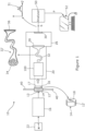
- FIG 1 there is shown schematically apparatus 10 for spectral analysis of a sample 12 such as a pharmaceutical dosage form, which could for example be an oral solid dosage form such as a tablet or capsule, although other types of dosage forms or indeed other kinds of objects altogether may be analysed using apparatus and techniques described herein.
- a sample 12 such as a pharmaceutical dosage form
- a pharmaceutical dosage form which could for example be an oral solid dosage form such as a tablet or capsule, although other types of dosage forms or indeed other kinds of objects altogether may be analysed using apparatus and techniques described herein.
- the apparatus 10 is arranged and operated to provide improved consistency of spectral or other optical analysis across a plurality of similar samples 12, for example across a batch of pharmaceutical dosage forms which are intended to be substantially identical.
- Dosage forms of such a batch may typically be superficially identical or very similar, for example in terms of shape, size and composition, but may still comprise defects and/or variations especially in internal chemical content and composition. It may be important to detect such defects and variations as part of a manufacturing process or other test scenario.
- Tablets are manufactured in a variety of shapes, sizes and colours. Some tablets may be of multiple different colours. Tablet shapes include cylindrical or elliptical prism forms, often with bevelled edges, spherical, ovoid, lozenge forms and so forth. Tablets are frequently embossed or debossed with markings such as alphanumeric codes and other symbols, slots to assist breaking into parts, and other surface features. Some tablets carry printed surface markings, for example including alphanumeric codes and other symbols. Tablets are manufactured both in coated forms in which a surface layer comprises different components to an underlying tablet core, and in uncoated forms.
- composition capsules typically comprise an encapsulating sleeve containing pharmaceutical powders or sometimes gels or fluids.
- a typical shape for a capsule is cylindrical with rounded ends, but other geometries are sometimes used, for example flattened cylindrical forms.
- the encapsulating sleeve is typically formed by joining two opposing end sections, which are frequently of different colours. Capsules are often printed with surface markings such as alphanumeric codes and other symbols.
- the apparatus illustrated in figure 1 is particularly arranged to carry out Raman spectral analysis of samples 12 such as pharmaceutical dosage forms, although other types of spectral or more generally optical analysis could also or instead be implemented.
- the mode of operation of the apparatus illustrated in figure 1 is one of transmission Raman spectroscopy, in which probe light is delivered to an delivery region 13 on a first surface 14 of the sample 12 by delivery optics 16, and elements of the probe light which have been forward scattered through the sample 12 are collected from a collection region 17 on a second surface 18 of the sample by collection optics 20 for detection of Raman scattered elements in the collected light.
- transmission Raman techniques are described for example in WO2007/113566 .
- the second surface 18 may be spaced from the first surface 14 in such a manner that forward scattering brings Raman scattered elements of the probe light to the second surface to be collected and detected, so that the sample is analysed in a transmission or forward scattering geometry.
- the second surface 18 is on an opposite side of the sample to the first surface 14.
- An example of this is illustrated for a tablet dosage form sample 12' shown in expanded view in figure 1 , in which the first surface 14 is a first largely flat surface of the tablet dosage form 12', and the second surface 18 is a second largely flat surface of the tablet dosage form 12' which is opposite the first surface 14.
- each of the first and second surfaces may be substantially parallel, often circular, and spaced from each other by a sidewall, and such that the dosage form has a generally rectangular cross section as seen in the main part of figure 1 .
- the shapes and sizes of the delivery and collection regions 13, 17 may be chosen according to need and design.
- the delivery region may be a circular or elliptical region which is around 1 - 10 mm in diameter
- the collection region may be a circular or elliptical region which is of a similar size.
- the delivery region need not be a contiguous region, but could be made up of a plurality of separated areas, and the same is so for the collection region.
- the apparatus of figure 1 comprises a laser light source 22 arranged to generate a beam of probe light, typically of infrared laser light, which the delivery optics 16 direct to the sample 12.
- the collection optics 20 are arranged to receive probe light following forward scattering, including Raman scattering, within the sample 12, and to deliver the collected probe light to a spectrometer 26.
- the spectrometer 26 may be a dispersive spectrometer, such as a Kaiser Optical Technologies Holospec device.
- the collection optics deliver the collected probe light to an entrance port 28 of the spectrometer 26.
- the entrance port 28 may typically be a slit with a width chosen to provide a suitable compromise between light gathering and spectral resolution, and a length related to a size of an imaging component 30.
- other forms of a port may be used such as a binary coded port.
- Spectral features S of the collected probe light may then be detected by a CCD or other imaging component 30 forming part of the spectrometer 26.
- the detected Raman spectral features S illustrated using a small graph in figure 1 , may then be passed in the form of electronic data from the spectrometer 26 to an analyser 50 for further processing and use.
- the Raman spectral features 31, and / or further data derived from the spectral features may then be passed to other entities such as a locally connected personal computer 52, over one or more data networks, or stored on a data carrier for future use.
- the collection optics typically comprise an optical fibre bundle 32, or sometimes just a single optical fibre, which carries the collected light to the spectrometer 26, typically to the entrance port 28.
- the optical fibre bundle is also illustrated as bundle 32' in expanded view, in which it can be seen that the optical fibre bundle may present an entry face 34 in which the ends of the separate optical fibres are clustered in a substantially circular envelope, for example being hexagonally close packed of similar, and an exit face 36 in which the ends of the separate optical fibres are distributed along an elongate envelope, for example in a single line.
- the laser light source 22 may operate in the near infrared, for example around 700 nm to 1000 nm, either as a continuous wave or pulsed source laser.
- Suitable average optical output power delivered to the sample 12 may be around 50 to 1200 mW, and a suitable spot diameter of the probe light beam at the sample 12 may be in the region of around 1 to 10 mm. Particularly small spot sizes may be avoided due to risks of heating or optical damage to the sample under test.
- the collection optics 20 are usually designed to incorporate very good suppression of the wavelength band (i.e. fundamental wavelength) of the probe light as emitted by the laser source 22.
- Raman scattering cross sections are very small, so without such suppression the fundamental wavelength is likely to adversely affect accurate detection of the Raman spectral features, even though these may be spaced by tens of nanometers or more in wavelength from the laser wave band.
- This suppression may be achieved using one or more optical filters such as holographic notch or low pass filters within the collection optics 20 to suppress the laser waveband light which has been elastically scattered off, through or around the sample to be tested, as discussed in more detail below.
- the sample 12 may be supported or held in various ways by a support 40.
- support 40 maybe provided by frame within which the sample rests or is held, by jaws of a robot manipulator or in other ways. Suppression of the laser waveband light in the collection optics 20 when detecting Raman spectral features 33 reduces the need to avoid stray probe light reflecting or scattering around the sample 12 and into the collection optics, as would usually be necessary if using infrared absorption spectroscopy and some other spectroscopic techniques.
- the sample 12 to be tested may be suspended by the support 40 without particular need for an optical seal around the sides of the sample between the delivery optics 26 and collection optics 30 to prevent such stray light.
- the analyser 50 may be arranged to determine one or more properties P of the sample 12 from the Raman spectral features 31 provided by the spectrometer 26, such as the various chemical properties mentioned above.
- the analyser 34 may be arranged to detect aspects such as the magnitudes of particular Raman spectral peaks and other features which represent particular chemical components expected or looked for in the sample under test, broader spectral matches to spectra or multiple spectral features of such components, and so forth, for example with reference to one or more data libraries defining expected spectra and/or particular spectral features of such components.
- Spectral data S and/or determined properties P of the tested sample may be used in various ways, for example being stored locally and/or remotely, transmitted across a network, further analysed, used to control a process such as a manufacture process used to create the sample under test, and so forth.
- the local personal computer 52 is shown as receiving the determined properties P , and may for example provide output of aspects of the determined properties to a person monitoring the apparatus 10, for example in the form of displays of deviations of determined properties from expected values, audible or visible alerts to bring the attention of such a person to sufficiently significant deviations, and so forth.
- the Raman spectral features S output by the spectrometer 26 can be detected as an average or other representative data set for the sample as a whole, at least to the extent that the whole sample is represented in the collected light.
- the transmission Raman technique illustrated in figure 1 is particularly good at sampling the bulk of a sample such as a dosage form, with collected light carrying Raman spectral features arising from a broad volume within the sample.
- the determined properties P can be properties of a dosage form or other sample as a whole and consistently comparable between tested dosage forms or other samples.
- the detected intensity of Raman spectral features such as peaks can vary slightly depending on the precise positioning and alignment of the sample under test. Then, because practical spectrometers also display slight shifts in apparent detected wavelength as well as detected intensity depending on the spatial and angular distributions of collected light at the entrance port or slit, the detected spectral position of Raman spectral features such as peaks can also vary slightly depending on the precise positioning and alignment of the dosage form under test.
- the collection optics 20 of figure 1 therefore comprises de-imaging optics, or more specifically Koehler integration optics 100, which operate to remove image structure from the light collected from the sample 12 in transmission of this light to the entrance port 28 of the spectrometer 26. By removing such image structure, variations in position or orientation of the sample with respect to the collection optics have less effect on the distribution of light across the spectrometer port.
- This process can be described in various ways, for example as processing the collected light such that the collected light from each point of the collection region is distributed across most or all of the entrance port of the spectrometer. In this respect, each point of the collection region may ideally contribute equally to each part of the light entering the entrance port, but of course this complete level of de-imaging is not required in order to provide a useful level of image information removal.
- Koehler integration optics to achieve this effect also maintains reasonably efficient use of the available collected light, despite the increased number of optical elements which may be required in the collection optics. This can be important for many reasons.
- efficient use of the collected light enables exposure and integration times to be reduced (many seconds or even minutes may often be needed), probe light power to be reduced (making the laser or other light source easier or cheaper to implement with required levels of power consumption, stability and so forth, as well as reducing potential for light/heating damage to the sample), and makes achieving a desired spectral resolution and detector sensitivity easier.
- FIG 2 illustrates some different ways in which aspects of figure 1 may be implemented more generally. Details of figure 1 and as described above may be included in the arrangement of figure 2 as desired.
- no laser light source 22 is depicted. Illumination of the sample 12 may take place using a laser light source 22 as depicted in figure 1 using delivery optics, but instead the light source 22 could be provided by any light source suitable for the spectrometry to be carried out, and not necessarily by a laser source.
- an LED or other broadband light source could be used with suitable filtering to achieve the required spectral narrowing for the implemented spectroscopy technique..
- the sample 12 may be the whole or part of an object which is to be tested in situ, for example an object in a warehouse or on a conveyor belt, or a surface in a building, or an object on a table.
- a transmission geometry such that the probe light is directed to a delivery region 13 spaced from or opposite to the collection region 17, so that the probe light is forward scattered through a bulk of the sample before emerging for collection from the collection region 18, in figure 2 no particular geometry is shown.
- the sample may also or instead be illuminated by probe light in various other ways, for example with probe light being provided directly onto some or all of the collection region from which the collection optics collect probe light for spectral analysis in a reflection or backscattering geometry, in which case the collection and delivery regions may be described as coincident or overlapping.
- the probe light could be delivered to the sample along or proximal to the collection beam path, for example by using a partially reflecting or other mirror, or along some other path for example off-axis with respect to the collection path.
- Other geometries may include delivery of probe light at some intermediate angle between transmission and backscatter geometries, for example oblique or at right angles to the collection path, for example being directed to side walls or side portions of the sample.
- the collection optics 20 are arranged to collect probe light scattered from a collection region 17 of the sample, which may be all of the visible surface of the sample from the perspective of the collection optics, or a smaller part of the visible surface as seen in figure 2 .
- the collection region may be a single contiguous region, or could comprise two or more separate regions. Although a broadly circular collection region may be consistent with use of geometric optics in the collection optics, the collection region could have various other shapes or forms.
- the sample could be positioned quite close to the collection optics, or at a greater distance in which case suitable telescopic optics could be included within the collection optics.
- the spectrometer 26 is arranged to receive the collected probe light from the collection optics at the entrance port 28 of the spectrometer, and to detect spectral features in the received probe light.
- the collection optics as shown in figure 2 comprise Koehler integration optics 100 arranged to process the collected probe light for passing to the entrance port of the spectrometer as described elsewhere in this document.
- An optical fibre or fibre optic bundle 32 as described in respect of figure 1 may be used to carry processed light from the Koehler integration optics to the spectrometer, or other optical arrangements may be used.
- the Koehler integration optics may be arranged to direct the processed light directly onto the entrance port, optionally via one or more relays or other optical arrangements as discussed below.
- an analyser 50 is arranged to receive spectral data, comprising detected spectral feature such as peak positions and intensities, from the spectrometer 26, and to determine one or more properties of the sample 12 from the detected spectral features.
- the apparatus may be arranged to carry out Raman spectroscopy of the sample, so that the detected spectral features are then Raman spectral features, although other types of spectroscopy such as fluorescence, infrared absorption absorption, or visible light reflectance spectrometry may be used
- the Koehler integrator or Koehler integration optics 100 of figures 1 and 2 can be implemented in a variety of ways known to the skilled person. However, specific technical issues related to providing light from a sample to a spectrometer have prompted the inventors to consider a number of particular arrangements which address some of those needs.
- the Koehler integration optics 100 comprise a collector 110 and a condenser 120.
- the collector 110 is arranged to receive probe light which is scattered from the collection region 17 at the sample 12. Although in figure 3 the collector 110 receives the collected light directly from the collection region 17, this may take place instead via one or more other optical elements or devices, such as a telescope, a relay, one or more mirrors, and so forth (not shown).
- the collector 110 is arranged to form a virtual image 17' of the collection region at or proximal to the condenser 120.
- the condenser 120 is arranged to form an image, typically also a virtual image, at an output plane of the 114 of the Koehler integration optics.
- the image formed at the output plane 114 is an image of an intermediate plane 112 which is located at or proximal to the collector 110.
- the output plane 114 is located at or proximal to the entry face 34 of the fibre optic bundle 32 depicted in figure 1 .
- the output plane could instead be a plane used as an input plane to a relay or other further optics which in turn images the output plane onto the entry face 34 of the fibre optic bundle, or the condenser 120 or further relay or other optics could form an image of the intermediate plane at or proximal to the entry port 28 of the spectrometer itself.
- the Koehler integration optics 100 may be provided with a condenser diaphragm 116 located at, or just ahead of the condenser 120, which may serve to limit the size of the virtual image 17' of the collection region formed at the condenser and to exclude unwanted light from degrading the image of the intermediate plane which is formed at the output plane.
- the condenser diaphragm 116 may be used to define the perimeter of the virtual image 17' of the collection region 17 formed at or proximal to the condenser, thereby assisting in defining the effective extent of the collection region itself, although this may additionally or alternatively be defined by other diaphragms within the collection optics 20.
- the collector 110 and condenser 120, and other optical elements of the Koehler integration optics may each be provided by single lenses, compound lenses, or combinations of such single and/or compound lenses, each of which may be of spherical or aspherical form according to the detail of the design.
- the focal length and optical diameter of the collector 110 may be around 25 mm and 15 mm respectively.
- the focal length and optical diameter of the condenser 120 may be much smaller, for example around 3 mm and 3 mm respectively, giving an effective numerical aperture of about 2.5.
- spectral filters may be included within the collection optics 20, and conveniently within the Koehler integration optics.
- the apparatus is to carry out Raman spectroscopy of the sample, then typically it will be very desirable to provide one or more spectral filters which exclude the wavelengths of the original laser light from entering the spectrometer but permit the Raman scattered wavelengths of interest to pass.
- notch filters or more usually low pass filters which exclude the original laser light may be used, although various other types of spectral filter may be used depending on the circumstances.
- such spectral filters may be of holographic or dielectric (multilayer) types, whereby the spectral properties of the filter are somewhat dependent upon the angle of incidence of light at the filter, so that arranging such filters in a region of the collection optics where the light is reasonably well collimated can be important to avoid spectral and other artefacts being introduced.
- two or more such filters are used, they typically function more effectively if spaced further apart, for example by a distance of around the diameter of each filter or more.
- the collection optics 20 may comprise one or more groups of collimator lenses and one or more spectral filters disposed within each group of collimator lenses, each group of collimator lenses being arranged such that the collected light is at least partly collimated when passing through the one or more spectral filters disposed within the group.
- the degree of collimation required may typically need to be to within about 2 to 3 degrees from the optical axis in order to largely avoid the undesirable effects of non-collimation, although other amounts of collimation may be used depending on the design constraints of the particular apparatus, for example within about 5 degrees.
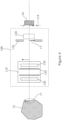
- Figure 4 shows an adaptation of the arrangement of figure 3 in which a group of collimator lenses is formed using collimator lenses 130 comprised in the collector 110, and one or more said spectral filters 132 are also comprised within the collector, located between the collimator lenses 130.
- the collector both functions to form a virtual image of the collection region at the condenser 120 or condenser diaphragm 116, and to provide adequate collimation of the light within the collector 130 to permit spectral filters 132 to perform their function sufficiently well.
- the collector 110 may therefore be implemented using a pair of simple or compound collimator lenses 130, with the one or more spectral filters located between the lenses.
- Each of the collimator lenses may for example have a focal length of about 30 mm and an optical diameter of about 25 mm, and the collimator lenses may be typically spaced by about 100 mm in order to provide adequate space for the spectral filters 132 to operate effectively.
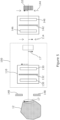
- Figure 5 shows an adaptation of the arrangements of figures 4 and 5 in which one, or potentially more than one, spectral filter 132 is optionally comprised within the collector, for example between collimator lenses 130 comprised in the collector 110, and one or more further spectral filters 142 are comprised within an output relay 140 which is arranged to relay the output plane 114 of the Koehler integration optics on to a second output plane 144, which could be located at the entry face 34 of the optical fibre bundle 32 as shown in the figure, or directly at the entrance port 28 of the spectrometer.
- one, or potentially more than one, spectral filter 132 is optionally comprised within the collector, for example between collimator lenses 130 comprised in the collector 110, and one or more further spectral filters 142 are comprised within an output relay 140 which is arranged to relay the output plane 114 of the Koehler integration optics on to a second output plane 144, which could be located at the entry face 34 of the optical fibre bundle 32 as shown in the figure, or directly at the entrance port 28
- the output relay may for example comprise a pair of collimation lenses 146 with the one or more further spectral filters 142 located between these collimation lenses. This arrangement permits greater separation of the spectral filters 132, 142, although achieving adequate collimation of the light within the output relay may be difficult to achieve alongside a reasonably high numerical aperture into the second output plane 144.
- the arrangement of figure 5 also lacks the condenser diaphragm seen in figures 3 and 4 , so absent some other arrangement for limiting the collection region such as an aperture proximal to the sample itself, the one or more spectral filters 132 within the collector 110 may allow a significant amount of high angle of incidence laser wavelength light arising from various surfaces in the collection optics (such as lens edges or anodised surfaces) to scatter on through the system.
- an optional sample diaphragm 148 is located proximally to the sample 12, to help prevent stray probe light from outside of the collection region 17 from entering the collection optics.
- FIG. 6 shows a further adaptation which can be applied to any of the previous arrangements, in which the sample diaphragm 148 is separated from the sample by a sample relay 150 which is arranged to form a virtual image of the sample 12 at the sample diaphragm 148, which thereby assists in defining the scope of the collection region 17 on the sample 12 and prevents further propagation of light from outside the collection region through the collection optics.
- the sample relay 150 may constructed in a similar manner to the output relay 140 discussed above in connection with figure 5 , for example comprising a pair of collimation lenses 156 and one or more spectral filters 152 located between the collimation lenses. However, in other embodiments a single simple or compound lens could be used to provide the sample relay 150. Similarly, in figure 6 the collector 110 is illustrated as comprising a pair of collimation lenses 130, and one or more spectral filters 132 located between the collimation lenses, but a single simple or compound lens could instead be used.
- the first collimation lens 156 of the sample relay 150 may have focal length of about 60 mm to provide a desired spacing from the sample, and an optical diameter of about 25 mm, and the second collimation lens may have a focal length of about 35 mm and an optical diameter of about 25 mm.
- the first and second collimation lenses 130 of the collector 110 may then each have a focal length of about 30 mm and a diameter of about 25 mm, and the single lens of the condenser may have a focal length and a diameter of about 3 mm, with these small values being used in order to provide a sufficiently high numerical aperture of around 2.5 at the output plane 114 for coupling (via a further relay if desired) into the optical fibre bundle or directly into the entrance port of the spectrometer.
- the Koehler integration optics generally shown in figures 1 and 2 can be implemented in various other ways. Using conventional, single aperture lenses in the collector and condenser can lead to minor deviations, in an approximately Gaussian distribution, of light intensity across the output plane. Such effects can be mitigated using an arrangement such as that shown in figure 7 in which the collector 110 comprises a collector lenslet array 170, and the condenser 120 comprises a condenser lenslet array 172.
- the two lenslet arrays are matched so that each lenslet of one array corresponds to one of the other array, the arrays typically being of the same size and optical properties.
- the two lenslet arrays may be co-focal, so that each lenslet of each array is at or close to the focal point of a corresponding lenslet of the other array.
- the lenslet arrays 170, 172 subsample the apertures of the collector and condenser, and these subsamples are then superimposed again at the output plane 114, providing additional mixing of different parts of the collection region onto the output plane.
- the collector lenslet array 170 may follow a collector lens 174 within the collector 110, so as to subsample the aperture of the collector lens 174, and the condenser lenslet array 172 may similarly precede a condenser lens 176 in the condenser.
- One or more spectral filters 178 may be provided in one or both of the collector 110 and condenser 120, preferably before the lenslet array in the collector, and/or after the lenslet array in the condenser as shown in figure 7 .
- the matched lenslet arrays may be rectilinear arrays of, for example, 3x3 to 5x5 lenslets. Using more lenslets in each array provides for increased performance in terms of subsampling the aperture and overlaying the subsamples at the output plane, but because accurate alignment of the lenslets is important in order to maintain light throughput, increasing the number of lenslets further may make construction more difficult.
- the lenslet arrays could instead be hexagonally packed or otherwise arranged, typically comprising between about 5 and 30 lenslets.
- the lenslet array arrangements illustrated in figure 7 may be combined with various other construction details already discussed above. If an output relay as depicted in figure 5 is used with the lenslet arrangement, then it may be desirable to include an output plane diaphragm at the output plane 114 ahead of the output relay, which may include one or more spectral filters as discussed above.
- a sample relay as depicted in figure 6 may also or instead be used in combination with the described lenslet arrays, implementing one or both of the sample aperture 148 between the sample relay and the collector, and the spectral filters 152 within the sample relay.
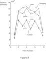
- Figure 8 depicts results of using an arrangement similar to that of figures 1 and 3 to sample light from a collection region of a pharmaceutical tablet (a Trazadone (RTM) tablet was used), during illumination of the opposite side of the tablet using infrared laser light.
- Collection optics 20 comprising Koehler integration optics 100 similar to those of figure 3 included an optical fibre bundle, and the Koehler integration optics 100 were arranged to process light from a collection region of the tablet and to direct the processed light onto an entry face 32 of the bundle. Then, instead of coupling the other end of the optical fibre bundle to the spectrometer, light intensity emerging from each optical fibre at the exit face 36 was measured.
- the collection optics were arranged such that the Koehler integration optics could be included in or excluded from the collection of the light from the tablet, without any change in the shape or size of the collection region. This was achieved by ensuring that the collection area in both cases had equivalent illuminations so that the capturable photon flux remained the same.
- the Koehler integration optics were excluded, in an "imaging" mode the collection optics formed an image of the collection region 17 directly onto the entry face 32 of the bundle.
- figure 8 presents a graph in which the x-axis corresponds to each of the eight optical fibres present in the bundle, and the y-axis to the detected intensity of light (in arbitrary units) emerging from each optical fibre at the exit face 36.
- Each of the two solid lines depicts the measured intensities, without Koehler integration optics being used (imaging mode), when the collection region was aligned accurately with a centre of the tablet (labelled “0 mm” and points as "x”), and the second when the collection region was moved a small distance of 1 mm away from this position (labelled “1 mm” and points as “o”).
- the broken lines depict the corresponding measurements with the Koehler integration optics being used (Koehler mode).
- the invention provides methods of constructing and methods of operating apparatus which is described herein, and corresponding methods of carrying out analysis of one or more samples.
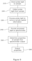
- Figure 9 illustrates such a method, but any of the process steps and operations discussed above may be implemented in such a method.
- probe light is directed to the sample 12.
- the probe light may be laser probe light, or some other probe light suitable for carrying out the desired spectroscopy as discussed above.
- Probe light scattered from the sample 12 is then collected at step 220.
- the collection of probe light may be arranged such that the probe light has been forward scattered through the sample (in a transmission geometry) or in other ways as discussed above.
- the scattering may involve various spectral processes such as Raman scattering, infrared absorption and so forth.
- the collected probe light is processed to remove some or all of the spatial information arising from the sample. This may be described as removing image information in respect of a collection region of the sample, or in other ways as set out above, and in particular Koehler integration may be used for this process. Typically during this process, light from each point of the collection region on the sample is mixed with the light from other points of the collection region, so as to be distributed across some or all of the output of the process.
- the processed collected light is then passed to a spectrometer at step 230, and the spectrometer is used to detect spectral features of the collected light.
- the processed light may be passed to an extended entrance port such as a slit of the spectrometer, which may typically be a dispersive spectrometer implemented using a diffraction grating or similar. Because such spectrometers are susceptible to slight variations in wavelength response or calibration along the entrance port or slit, providing collected light from which spatial information of the sample has been removed improves consistency of spectral response of the apparatus under slight movements or geometric variations of the sample.
- Spectral features output by the spectrometer such as a full or part spectrum, or properties of individual features such as one or more particular peak intensities, are then used at step 250 to determine one or more properties of the sample, such as presence or a measurement of one or more chemical components.
- properties, or information relating to such properties such as an alarm indicating a property falls outside a desired range, are output at step 260.
- Such computer systems will typically comprise one or more microprocessors to execute such computer program code, memory to store such programs and related data, and suitable input and output facilities which may include for example wired or wireless data connections, non-volatile storage, as well as visual displays, and input device such as keyboards and mice if required.
- the analyser 50 for example, as depicted in figures 1 and 2 may comprise one or more suitable computer systems programmed with suitable software to receive Raman spectral features S from the spectrometer 26, analyse and process those spectral features in various ways for example to reduce noise, transform into desired forms, and measure particular spectral features, and to match particular spectral features with those of known or expected components or characteristics of the sample under test in order to determine properties P of the sample.
- Libraries of spectral features which may be used for such comparisons are available for example from S.T. Japan or Sigma-Aldrich.
Landscapes
- Physics & Mathematics (AREA)
- Spectroscopy & Molecular Physics (AREA)
- General Physics & Mathematics (AREA)
- Health & Medical Sciences (AREA)
- Life Sciences & Earth Sciences (AREA)
- General Health & Medical Sciences (AREA)
- Pathology (AREA)
- Chemical & Material Sciences (AREA)
- Biochemistry (AREA)
- Immunology (AREA)
- Analytical Chemistry (AREA)
- Engineering & Computer Science (AREA)
- Molecular Biology (AREA)
- Biophysics (AREA)
- Medical Informatics (AREA)
- Veterinary Medicine (AREA)
- Public Health (AREA)
- Animal Behavior & Ethology (AREA)
- Surgery (AREA)
- Biomedical Technology (AREA)
- Heart & Thoracic Surgery (AREA)
- Bioinformatics & Cheminformatics (AREA)
- Medicinal Chemistry (AREA)
- Food Science & Technology (AREA)
- Pharmacology & Pharmacy (AREA)
- Nuclear Medicine, Radiotherapy & Molecular Imaging (AREA)
- Investigating, Analyzing Materials By Fluorescence Or Luminescence (AREA)
Claims (12)
- Vorrichtung zur Spektralanalyse einer Probe (12), aufweisend:eine Abgabeoptik (16), die so angeordnet ist, dass sie Probenlicht auf einen Abgabebereich (13) einer Probe (12) richtet; wobei die Probe eine feste pharmazeutische Darreichungsform ist;eine von der Abgabeoptik (16) getrennte Sammeloptik (20), die so angeordnet ist, dass sie Probenlicht sammelt, das von einem Sammelbereich (17) der Probe (12) gestreut wird; undein Spektrometer (26) mit einer Eintrittsöffnung (28), wobei das Spektrometer so angeordnet ist, dass es das gestreute Licht, das von der Sammeloptik (20) gesammelt und verarbeitet wurde, an der Eintrittsöffnung (28) des Spektrometers (26) empfängt und Spektralmerkmale in dem empfangenen Sondenlicht erkennt;einen Analysator (50), der so angeordnet ist, dass er die Spektralmerkmale vom Spektrometer empfängt, analysiert und verarbeitet, um eine oder mehrere Eigenschaften der festen pharmazeutischen Darreichungsform zu bestimmen;wobei die Sammeloptik (20) eine Köhler-Integrationsoptik (100) umfasst, die so angeordnet ist, dass sie das gestreute Licht sammelt und verarbeitet,wobei die Sammeloptik (20) ein Bündel von Lichtwellenleitern (32) mit einer Eintrittsfläche (34) umfasst, die so angeordnet ist, dass sie das gesammelte Sondenlicht nach der Verarbeitung durch die Köhler-Integrationsoptik (100) empfängt, und mit einer Austrittsfläche (36), die so angeordnet ist, dass sie das gesammelte Sondenlicht an die Eingangsöffnung (28) des Spektrometers (26) liefert;wobei die Köhler-Integrationsoptik (100) das gestreute Licht sammelt und verarbeitet, so dass das gestreute Licht von jedem Punkt des Sammelbereichs (17) gesammelt und verarbeitet wird, um über die Eintrittsfläche (34) des Bündels von optischen Fasern verteilt zu werden und folglich über die Eintrittsöffnung (28) des Spektrometers (26) verteilt zu werden; undwobei sich der Sammelbereich (17) auf einer dem Abgabebereich (13) gegenüberliegenden Seite der Probe (12) befindet.
- Vorrichtung nach Anspruch 1,
wobei die erfassten spektralen Merkmale Raman spektrale Merkmale sind. - Vorrichtung nach einem der vorhergehenden Ansprüche, wobei die Köhler-Integrationsoptik einen Kollektor, der so angeordnet ist, dass er das gesammelte Licht aus dem Sammelbereich der Probe empfängt, und einen Kondensor, der so angeordnet ist, dass er das gesammelte Licht aus dem Kollektor empfängt, umfasst;insbesondere, wobei die Köhler-Integrationsoptik eine Zwischenebene am oder in der Nähe des Kollektors und eine Ausgangsebene definiert, wobei der Kollektor so angeordnet ist, dass er ein Bild des Sammelbereichs der Probe am oder in der Nähe des Kondensators erzeugt, und der Kondensator so angeordnet ist, dass er ein Bild der Zwischenebene an der Ausgangsebene erzeugt;insbesondere, wobei die Sammeloptik ein Bündel von optischen Fasern umfasst, wobei das Bündel eine Eintrittsfläche, die so angeordnet ist, dass sie das gesammelte Probenlicht nach der Verarbeitung durch die Köhler-Integrationsoptik empfängt, und eine Austrittsfläche aufweist, die so angeordnet ist, dass sie das gesammelte Probenlicht an den Port des Spektrometers liefert, und wobei die Ausgangsebene an oder in der Nähe der Eintrittsfläche angeordnet ist.
- Vorrichtung nach Anspruch 3, wobei die Sammeloptik mindestens eine Gruppe von Kollimatorlinsen und mindestens einen Spektralfilter umfasst, der in der mindestens einen Gruppe von Kollimatorlinsen angeordnet ist, wobei die mindestens eine Gruppe von Kollimatorlinsen so angeordnet ist, dass das gesammelte Licht zumindest teilweise kollimiert wird, wenn es durch den mindestens einen Spektralfilter hindurchtritt, der in der Gruppe angeordnet ist;wobei optional eine Gruppe von Kollimatorlinsen Linsen des Kollektors sind und der mindestens eine Spektralfilter im Kollektor enthalten ist; und/oderwobei optional eine Gruppe von Kollimatorlinsen in einer Ausgangs-Relaislinsenanordnung enthalten ist, die so angeordnet ist, dass sie ein Bild der Ausgangsebene vom Kondensor weiterleitet, und ein oder mehrere Spektralfilter im Ausgangssignal enthalten sind.
- Vorrichtung nach Anspruch 4, wobei die Gruppe von Kollimatorlinsen in einer Proben-Relaislinsenanordnung enthalten ist, die so angeordnet ist, dass sie ein übertragenes virtuelles Bild des Sammelbereichs zur Abbildung durch den Kollektor erzeugt, und wobei ein oder mehrere Spektralfilter in dem Proben-Relais enthalten sind;
wahlweise ferner umfassend eine Probenblende zwischen der Probenrelaislinse und dem Kollektor, wobei die Probenrelaislinse so angeordnet ist, dass sie das weitergeleitete virtuelle Bild des Sammelbereichs an der Probenblende bildet. - Vorrichtung nach Anspruch 4 oder 5, wobei die erfassten spektralen Merkmale Raman-spektral sind, das auf den Abgabebereich der Probe gerichtete Sondenlicht mindestens eine Sondenwellenlänge aufweist und der mindestens eine Spektralfilter einen Spektralfilter umfasst, der so angeordnet ist, dass er Licht der Sondenwellenlängen blockiert, aber Licht der Raman-spektralen Merkmale durchlässt.
- Vorrichtung nach Anspruch 3 oder 4, die ferner eine Probenblende und eine Proben-Relaislinsenanordnung umfasst, die so angeordnet ist, dass sie ein übertragenes virtuelles Bild des Sammelbereichs an der Probenblende zur Abbildung durch den Kollektor erzeugt.
- Vorrichtung nach einem der Ansprüche 3 bis 7 umfasst ferner eine Kondensormembran an oder in der Nähe des Kondensors, so dass die Kondensormembran die Ausdehnung des virtuellen Bildes des Sammelbereichs, das durch den Kollektor an oder in der Nähe des Kondensors gebildet wird, begrenzt.
- Vorrichtung nach einem der Ansprüche 3 bis 8, wobei der Kollektor eine Kollektor-Linsenmatrix umfasst, der Kondensor eine Kondensor-Linsenmatrix umfasst;
wobei die Kollektor- und Kondensor-Linsenmatrix gegebenenfalls so co-fokal sind, dass die Linsenmatrizen die Öffnungen des Kollektors und des Kondensors unterabtasten und die Unterabtastungen an der Ausgangsebene überlagert werden. - Vorrichtung nach einem der vorhergehenden Ansprüche;wobei die pharmazeutische Dosierungsform mindestens eine der folgenden ist: eine Tablette; eine beschichtete Tablette; eine Kapsel; und eine Gelkapsel; und/oderwobei die pharmazeutische Dosierungsform mindestens eines der folgenden umfasst: Oberflächenmarkierungen; Prägung; Reliefprägung; eine Vielzahl von Oberflächenbereichen, die jeweils eine unterschiedliche Farbe aufweisen; und gedruckte Markierungen.
- Verfahren zur Spektralanalyse einer Probe (12), aufweisend:Leiten von Sondenlicht zu einem Abgabebereich (13) der Probe, wobei die Probe eine feste pharmazeutische Dosierungsform ist;Sammeln von Sondenlicht von einem Sammelbereich (17) der Probe;Verarbeiten des gesammelten Sondenlichts durch eine Köhler-Integrationsoptik (100), so dass das gesammelte Licht von jedem Punkt des Sammelbereichs (17) über eine Eingangsöffnung (28) eines Spektrometers (26) verteilt wird, umfassend Empfangen des gesammelten Sondenlichts durch eine Eintrittsfläche (34) eines Bündels von optischen Fasern (32) nach der Verarbeitung durch die Köhler-Integrationsoptik (100); unddas verarbeitete gesammelte Sondenlicht durch eine Austrittsfläche (36) des Bündels von Lichtwellenleitern (32) an die Eingangsöffnung (28) des Spektrometers (26) abzugeben;Empfangen des gesammelten Probenlichts durch eine Eintrittsfläche (34) eines Bündels von optischen Fasern (32) nach der Verarbeitung durch die Köhler-Integrationsoptik (100) und Abgeben des gesammelten Probenlichts durch eine Austrittsfläche (36) des Bündels von optischen Fasern (32) an die Eintrittsöffnung (28) des Spektrometers (26); undAnalysieren und Verarbeiten von Spektralmerkmalen, die vom Spektrometer ausgegeben werden, um eine oder mehrere Eigenschaften der festen pharmazeutischen Darreichungsform zu bestimmen;wobei sich der Abgabebereich (13) auf einer dem Sammelbereich (17) gegenüberliegenden Seite der Probe (12) befindet.
- Verfahren nach Anspruch 11,
wobei das Spektralmerkmal ein Raman-Spektralmerkmal ist.
Applications Claiming Priority (2)
| Application Number | Priority Date | Filing Date | Title |
|---|---|---|---|
| GB2007136.1A GB2594980B (en) | 2020-05-14 | 2020-05-14 | Spectral analysis of a sample |
| PCT/GB2021/050520 WO2021229201A1 (en) | 2020-05-14 | 2021-03-02 | Spectral analysis of a sample |
Publications (2)
| Publication Number | Publication Date |
|---|---|
| EP4150326A1 EP4150326A1 (de) | 2023-03-22 |
| EP4150326B1 true EP4150326B1 (de) | 2025-04-09 |
Family
ID=71135286
Family Applications (1)
| Application Number | Title | Priority Date | Filing Date |
|---|---|---|---|
| EP21709796.3A Active EP4150326B1 (de) | 2020-05-14 | 2021-03-02 | Spektralanalyse einer probe |
Country Status (5)
| Country | Link |
|---|---|
| US (1) | US12329496B2 (de) |
| EP (1) | EP4150326B1 (de) |
| CN (1) | CN115552224A (de) |
| GB (1) | GB2594980B (de) |
| WO (1) | WO2021229201A1 (de) |
Families Citing this family (5)
| Publication number | Priority date | Publication date | Assignee | Title |
|---|---|---|---|---|
| US12019272B2 (en) * | 2021-04-13 | 2024-06-25 | Oak Analytics Inc. | Optical spectrometer with high-efficiency optical coupling |
| JP7640397B2 (ja) * | 2021-07-28 | 2025-03-05 | アンリツ株式会社 | 物品検査装置 |
| JP2023137889A (ja) * | 2022-03-18 | 2023-09-29 | 株式会社トプコン | 穀物成分センサ及び穀物成分分析装置 |
| EP4671709A1 (de) | 2024-06-25 | 2025-12-31 | Serstech AB | Ramanspektroskopievorrichtung und verfahren zur durchführung von ramanspektroskopie an einer probe |
| CN119804417A (zh) * | 2025-01-26 | 2025-04-11 | 深圳技师学院(深圳高级技工学校) | 一种用于物质检测的激光扫描系统 |
Citations (1)
| Publication number | Priority date | Publication date | Assignee | Title |
|---|---|---|---|---|
| WO2007113566A2 (en) * | 2006-04-05 | 2007-10-11 | The Science And Technology Facilities Council | Raman analysis |
Family Cites Families (15)
| Publication number | Priority date | Publication date | Assignee | Title |
|---|---|---|---|---|
| DE3843876A1 (de) * | 1988-12-24 | 1990-07-12 | Leitz Wild Gmbh | Spektralmikroskop mit einem photometer |
| FI109149B (fi) * | 1999-09-29 | 2002-05-31 | Valtion Teknillinen | Spektrometri ja menetelmä optisen spektrin mittaamiseksi |
| US7126131B2 (en) * | 2003-01-16 | 2006-10-24 | Metrosol, Inc. | Broad band referencing reflectometer |
| WO2007092010A2 (en) * | 2005-02-09 | 2007-08-16 | Chemimage Corporation | System and method for electrostatic detection and identification of threat agents |
| US8623789B2 (en) * | 2009-09-21 | 2014-01-07 | Akonni Biosystems, Inc. | Integrated cartridge |
| US9662047B2 (en) | 2010-08-05 | 2017-05-30 | Massachusetts Institute Of Technology | Portable raman diagnostic system |
| US9915654B2 (en) * | 2012-09-28 | 2018-03-13 | The United States Of America, As Represented By The Secretary Of The Navy | Light microscopy chips and data analysis methodology for quantitative localized surface plasmon resonance (LSPR) biosensing and imaging |
| EP2946194B1 (de) * | 2013-01-17 | 2023-07-05 | Detector Electronics Corporation | Gasdetektor mit offener messstrecke |
| JP5884021B2 (ja) * | 2013-02-13 | 2016-03-15 | パナソニックIpマネジメント株式会社 | マルチスペクトル撮像装置およびマルチスペクトル撮像方法 |
| CN106705856B (zh) * | 2015-07-31 | 2019-05-14 | 南京理工大学 | 基于宽带光谱域显微干涉术的近红外位移传感装置及微位移量测量方法 |
| EP3336523A1 (de) * | 2016-12-14 | 2018-06-20 | F. Hoffmann-La Roche AG | Beleuchtungstechniken für proben |
| JP6861116B2 (ja) * | 2017-07-14 | 2021-04-21 | 株式会社荏原製作所 | 膜厚測定装置、研磨装置、および研磨方法 |
| CN109425572B (zh) * | 2017-08-30 | 2023-07-25 | 三星电子株式会社 | 用于光谱仪的收集光学系统和拉曼光谱系统 |
| CN110208294A (zh) * | 2019-06-18 | 2019-09-06 | 华东交通大学 | 基于柯勒照明的单像素显微成像方法及系统 |
| CN110286117A (zh) * | 2019-08-06 | 2019-09-27 | 北京华泰诺安探测技术有限公司 | 一种基于复眼透镜的拉曼探头 |
-
2020
- 2020-05-14 GB GB2007136.1A patent/GB2594980B/en active Active
-
2021
- 2021-03-02 CN CN202180034902.5A patent/CN115552224A/zh active Pending
- 2021-03-02 US US17/925,272 patent/US12329496B2/en active Active
- 2021-03-02 EP EP21709796.3A patent/EP4150326B1/de active Active
- 2021-03-02 WO PCT/GB2021/050520 patent/WO2021229201A1/en not_active Ceased
Patent Citations (1)
| Publication number | Priority date | Publication date | Assignee | Title |
|---|---|---|---|---|
| WO2007113566A2 (en) * | 2006-04-05 | 2007-10-11 | The Science And Technology Facilities Council | Raman analysis |
Also Published As
| Publication number | Publication date |
|---|---|
| US20230218174A1 (en) | 2023-07-13 |
| GB2594980A (en) | 2021-11-17 |
| US12329496B2 (en) | 2025-06-17 |
| EP4150326A1 (de) | 2023-03-22 |
| CN115552224A (zh) | 2022-12-30 |
| WO2021229201A1 (en) | 2021-11-18 |
| GB2594980B (en) | 2025-01-01 |
| GB202007136D0 (en) | 2020-07-01 |
Similar Documents
| Publication | Publication Date | Title |
|---|---|---|
| EP4150326B1 (de) | Spektralanalyse einer probe | |
| US7486395B2 (en) | System and method for a chemical imaging threat assessor with a probe | |
| US8094294B2 (en) | Multipoint method for identifying hazardous agents | |
| EP3743699B1 (de) | Vorrichtung zur ausrührung von raman-spektroskopie | |
| EP2021748B1 (de) | Spektrometer und interferometrisches verfahren | |
| US7542138B2 (en) | Sample container and system for a handheld spectrometer and method for using therefor | |
| US9182282B2 (en) | Multi-analyte optical computing system | |
| US7286222B2 (en) | Sample container and system for a handheld spectrometer and method for using therefor | |
| US9194799B2 (en) | Imaging based refractometers | |
| US7016037B2 (en) | Imaging spectrometer utilizing immersed gratings with accessible entrance slit | |
| US20120057743A1 (en) | System and method for fluorescence guided ingredient specific particle sizing | |
| US20130242115A1 (en) | Imaging based refractometer for hyperspectral refractive index detection | |
| US7321423B2 (en) | Real-time goniospectrophotometer | |
| Hamilton et al. | Hyperspectral imaging technology for pharmaceutical analysis | |
| US7864316B2 (en) | Spectrometric characterization of pharmaceutical heterogeneity | |
| US8643841B1 (en) | Angle-resolved spectroscopic instrument | |
| JP2018526647A (ja) | テストサンプルについての光吸収測定、および、基準サンプルについてのコンプライアンス測定を実施するための装置および方法 | |
| WO2025068325A1 (en) | Diffractive particle characterisation | |
| US11860103B2 (en) | Sample identification | |
| Vogt | Trends in remote spectroscopic sensing and imaging-experimental techniques and chemometric concepts | |
| US10578488B1 (en) | Compact light dispersion system | |
| US20110238327A1 (en) | Spectrometric characterization of heterogeneity | |
| WO2025235658A1 (en) | System and method for spectroscopic determination of chemical compositions from sample scans | |
| US20070159626A1 (en) | Method and Apparatus for High Resolution Spectroscopy | |
| Gorbunov et al. | Spectrophotometric apparatus for analyzing and monitoring the quality of a product |
Legal Events
| Date | Code | Title | Description |
|---|---|---|---|
| STAA | Information on the status of an ep patent application or granted ep patent |
Free format text: STATUS: UNKNOWN |
|
| STAA | Information on the status of an ep patent application or granted ep patent |
Free format text: STATUS: THE INTERNATIONAL PUBLICATION HAS BEEN MADE |
|
| PUAI | Public reference made under article 153(3) epc to a published international application that has entered the european phase |
Free format text: ORIGINAL CODE: 0009012 |
|
| STAA | Information on the status of an ep patent application or granted ep patent |
Free format text: STATUS: REQUEST FOR EXAMINATION WAS MADE |
|
| 17P | Request for examination filed |
Effective date: 20221209 |
|
| AK | Designated contracting states |
Kind code of ref document: A1 Designated state(s): AL AT BE BG CH CY CZ DE DK EE ES FI FR GB GR HR HU IE IS IT LI LT LU LV MC MK MT NL NO PL PT RO RS SE SI SK SM TR |
|
| P01 | Opt-out of the competence of the unified patent court (upc) registered |
Effective date: 20230527 |
|
| DAV | Request for validation of the european patent (deleted) | ||
| DAX | Request for extension of the european patent (deleted) | ||
| STAA | Information on the status of an ep patent application or granted ep patent |
Free format text: STATUS: EXAMINATION IS IN PROGRESS |
|
| 17Q | First examination report despatched |
Effective date: 20240321 |
|
| GRAP | Despatch of communication of intention to grant a patent |
Free format text: ORIGINAL CODE: EPIDOSNIGR1 |
|
| STAA | Information on the status of an ep patent application or granted ep patent |
Free format text: STATUS: GRANT OF PATENT IS INTENDED |
|
| RIC1 | Information provided on ipc code assigned before grant |
Ipc: A61B 5/00 20060101ALI20241105BHEP Ipc: G01J 3/02 20060101ALI20241105BHEP Ipc: G01J 3/44 20060101ALI20241105BHEP Ipc: G01N 21/95 20060101ALI20241105BHEP Ipc: G01N 21/47 20060101ALI20241105BHEP Ipc: G01N 21/31 20060101ALI20241105BHEP Ipc: G01N 21/3563 20140101ALI20241105BHEP Ipc: G01N 21/65 20060101AFI20241105BHEP |
|
| INTG | Intention to grant announced |
Effective date: 20241114 |
|
| GRAS | Grant fee paid |
Free format text: ORIGINAL CODE: EPIDOSNIGR3 |
|
| GRAA | (expected) grant |
Free format text: ORIGINAL CODE: 0009210 |
|
| STAA | Information on the status of an ep patent application or granted ep patent |
Free format text: STATUS: THE PATENT HAS BEEN GRANTED |
|
| AK | Designated contracting states |
Kind code of ref document: B1 Designated state(s): AL AT BE BG CH CY CZ DE DK EE ES FI FR GB GR HR HU IE IS IT LI LT LU LV MC MK MT NL NO PL PT RO RS SE SI SK SM TR |
|
| REG | Reference to a national code |
Ref country code: GB Ref legal event code: FG4D |
|
| REG | Reference to a national code |
Ref country code: CH Ref legal event code: EP |
|
| REG | Reference to a national code |
Ref country code: DE Ref legal event code: R096 Ref document number: 602021028877 Country of ref document: DE |
|
| REG | Reference to a national code |
Ref country code: IE Ref legal event code: FG4D |
|
| REG | Reference to a national code |
Ref country code: NL Ref legal event code: MP Effective date: 20250409 |
|
| PG25 | Lapsed in a contracting state [announced via postgrant information from national office to epo] |
Ref country code: NL Free format text: LAPSE BECAUSE OF FAILURE TO SUBMIT A TRANSLATION OF THE DESCRIPTION OR TO PAY THE FEE WITHIN THE PRESCRIBED TIME-LIMIT Effective date: 20250409 |
|
| REG | Reference to a national code |
Ref country code: AT Ref legal event code: MK05 Ref document number: 1783930 Country of ref document: AT Kind code of ref document: T Effective date: 20250409 |
|
| PG25 | Lapsed in a contracting state [announced via postgrant information from national office to epo] |
Ref country code: FI Free format text: LAPSE BECAUSE OF FAILURE TO SUBMIT A TRANSLATION OF THE DESCRIPTION OR TO PAY THE FEE WITHIN THE PRESCRIBED TIME-LIMIT Effective date: 20250409 Ref country code: ES Free format text: LAPSE BECAUSE OF FAILURE TO SUBMIT A TRANSLATION OF THE DESCRIPTION OR TO PAY THE FEE WITHIN THE PRESCRIBED TIME-LIMIT Effective date: 20250409 Ref country code: PT Free format text: LAPSE BECAUSE OF FAILURE TO SUBMIT A TRANSLATION OF THE DESCRIPTION OR TO PAY THE FEE WITHIN THE PRESCRIBED TIME-LIMIT Effective date: 20250811 |
|
| REG | Reference to a national code |
Ref country code: LT Ref legal event code: MG9D |
|
| PG25 | Lapsed in a contracting state [announced via postgrant information from national office to epo] |
Ref country code: GR Free format text: LAPSE BECAUSE OF FAILURE TO SUBMIT A TRANSLATION OF THE DESCRIPTION OR TO PAY THE FEE WITHIN THE PRESCRIBED TIME-LIMIT Effective date: 20250710 Ref country code: NO Free format text: LAPSE BECAUSE OF FAILURE TO SUBMIT A TRANSLATION OF THE DESCRIPTION OR TO PAY THE FEE WITHIN THE PRESCRIBED TIME-LIMIT Effective date: 20250709 |
|
| PG25 | Lapsed in a contracting state [announced via postgrant information from national office to epo] |
Ref country code: PL Free format text: LAPSE BECAUSE OF FAILURE TO SUBMIT A TRANSLATION OF THE DESCRIPTION OR TO PAY THE FEE WITHIN THE PRESCRIBED TIME-LIMIT Effective date: 20250409 |
|
| PG25 | Lapsed in a contracting state [announced via postgrant information from national office to epo] |
Ref country code: BG Free format text: LAPSE BECAUSE OF FAILURE TO SUBMIT A TRANSLATION OF THE DESCRIPTION OR TO PAY THE FEE WITHIN THE PRESCRIBED TIME-LIMIT Effective date: 20250409 |
|
| PG25 | Lapsed in a contracting state [announced via postgrant information from national office to epo] |
Ref country code: HR Free format text: LAPSE BECAUSE OF FAILURE TO SUBMIT A TRANSLATION OF THE DESCRIPTION OR TO PAY THE FEE WITHIN THE PRESCRIBED TIME-LIMIT Effective date: 20250409 |
|
| PG25 | Lapsed in a contracting state [announced via postgrant information from national office to epo] |
Ref country code: AT Free format text: LAPSE BECAUSE OF FAILURE TO SUBMIT A TRANSLATION OF THE DESCRIPTION OR TO PAY THE FEE WITHIN THE PRESCRIBED TIME-LIMIT Effective date: 20250409 |
|
| PG25 | Lapsed in a contracting state [announced via postgrant information from national office to epo] |
Ref country code: RS Free format text: LAPSE BECAUSE OF FAILURE TO SUBMIT A TRANSLATION OF THE DESCRIPTION OR TO PAY THE FEE WITHIN THE PRESCRIBED TIME-LIMIT Effective date: 20250709 |
|
| PG25 | Lapsed in a contracting state [announced via postgrant information from national office to epo] |
Ref country code: IS Free format text: LAPSE BECAUSE OF FAILURE TO SUBMIT A TRANSLATION OF THE DESCRIPTION OR TO PAY THE FEE WITHIN THE PRESCRIBED TIME-LIMIT Effective date: 20250809 |
|
| PG25 | Lapsed in a contracting state [announced via postgrant information from national office to epo] |
Ref country code: LV Free format text: LAPSE BECAUSE OF FAILURE TO SUBMIT A TRANSLATION OF THE DESCRIPTION OR TO PAY THE FEE WITHIN THE PRESCRIBED TIME-LIMIT Effective date: 20250409 |
|
| PG25 | Lapsed in a contracting state [announced via postgrant information from national office to epo] |
Ref country code: DK Free format text: LAPSE BECAUSE OF FAILURE TO SUBMIT A TRANSLATION OF THE DESCRIPTION OR TO PAY THE FEE WITHIN THE PRESCRIBED TIME-LIMIT Effective date: 20250409 Ref country code: SM Free format text: LAPSE BECAUSE OF FAILURE TO SUBMIT A TRANSLATION OF THE DESCRIPTION OR TO PAY THE FEE WITHIN THE PRESCRIBED TIME-LIMIT Effective date: 20250409 |
|
| PG25 | Lapsed in a contracting state [announced via postgrant information from national office to epo] |
Ref country code: CZ Free format text: LAPSE BECAUSE OF FAILURE TO SUBMIT A TRANSLATION OF THE DESCRIPTION OR TO PAY THE FEE WITHIN THE PRESCRIBED TIME-LIMIT Effective date: 20250409 |
|
| PG25 | Lapsed in a contracting state [announced via postgrant information from national office to epo] |
Ref country code: EE Free format text: LAPSE BECAUSE OF FAILURE TO SUBMIT A TRANSLATION OF THE DESCRIPTION OR TO PAY THE FEE WITHIN THE PRESCRIBED TIME-LIMIT Effective date: 20250409 |
|
| PG25 | Lapsed in a contracting state [announced via postgrant information from national office to epo] |
Ref country code: SK Free format text: LAPSE BECAUSE OF FAILURE TO SUBMIT A TRANSLATION OF THE DESCRIPTION OR TO PAY THE FEE WITHIN THE PRESCRIBED TIME-LIMIT Effective date: 20250409 |
|
| PG25 | Lapsed in a contracting state [announced via postgrant information from national office to epo] |
Ref country code: IT Free format text: LAPSE BECAUSE OF FAILURE TO SUBMIT A TRANSLATION OF THE DESCRIPTION OR TO PAY THE FEE WITHIN THE PRESCRIBED TIME-LIMIT Effective date: 20250409 |
|
| PLBE | No opposition filed within time limit |
Free format text: ORIGINAL CODE: 0009261 |
|
| STAA | Information on the status of an ep patent application or granted ep patent |
Free format text: STATUS: NO OPPOSITION FILED WITHIN TIME LIMIT |