EP4149708B1 - System for connecting electronic assemblies - Google Patents
System for connecting electronic assemblies Download PDFInfo
- Publication number
- EP4149708B1 EP4149708B1 EP21727397.8A EP21727397A EP4149708B1 EP 4149708 B1 EP4149708 B1 EP 4149708B1 EP 21727397 A EP21727397 A EP 21727397A EP 4149708 B1 EP4149708 B1 EP 4149708B1
- Authority
- EP
- European Patent Office
- Prior art keywords
- soldering
- module
- sintering system
- cold trap
- temperature
- Prior art date
- Legal status (The legal status is an assumption and is not a legal conclusion. Google has not performed a legal analysis and makes no representation as to the accuracy of the status listed.)
- Active
Links
- 230000000712 assembly Effects 0.000 title claims description 70
- 238000000429 assembly Methods 0.000 title claims description 70
- 238000001816 cooling Methods 0.000 claims description 161
- 238000000034 method Methods 0.000 claims description 143
- 230000008569 process Effects 0.000 claims description 136
- 238000005476 soldering Methods 0.000 claims description 90
- 238000005245 sintering Methods 0.000 claims description 62
- 229910000679 solder Inorganic materials 0.000 claims description 58
- 238000010438 heat treatment Methods 0.000 claims description 57
- 239000007789 gas Substances 0.000 claims description 54
- 239000012298 atmosphere Substances 0.000 claims description 22
- 238000007711 solidification Methods 0.000 claims description 15
- 230000008023 solidification Effects 0.000 claims description 15
- IJGRMHOSHXDMSA-UHFFFAOYSA-N Atomic nitrogen Chemical compound N#N IJGRMHOSHXDMSA-UHFFFAOYSA-N 0.000 claims description 12
- 239000007788 liquid Substances 0.000 claims description 7
- 229910052799 carbon Inorganic materials 0.000 claims description 6
- 229910001873 dinitrogen Inorganic materials 0.000 claims description 5
- 238000000605 extraction Methods 0.000 claims description 5
- 238000010926 purge Methods 0.000 claims description 4
- 238000000926 separation method Methods 0.000 claims description 2
- 238000003780 insertion Methods 0.000 claims 1
- 230000037431 insertion Effects 0.000 claims 1
- 239000000463 material Substances 0.000 description 21
- 238000011109 contamination Methods 0.000 description 10
- 239000000969 carrier Substances 0.000 description 9
- 239000000356 contaminant Substances 0.000 description 8
- BDAGIHXWWSANSR-UHFFFAOYSA-N Formic acid Chemical compound OC=O BDAGIHXWWSANSR-UHFFFAOYSA-N 0.000 description 7
- 239000000758 substrate Substances 0.000 description 7
- QVGXLLKOCUKJST-UHFFFAOYSA-N atomic oxygen Chemical compound [O] QVGXLLKOCUKJST-UHFFFAOYSA-N 0.000 description 6
- 238000004519 manufacturing process Methods 0.000 description 6
- 239000001301 oxygen Substances 0.000 description 6
- 229910052760 oxygen Inorganic materials 0.000 description 6
- 239000004065 semiconductor Substances 0.000 description 6
- 239000000126 substance Substances 0.000 description 6
- 238000004140 cleaning Methods 0.000 description 5
- 235000019253 formic acid Nutrition 0.000 description 5
- 230000008018 melting Effects 0.000 description 5
- 238000002844 melting Methods 0.000 description 5
- 239000002904 solvent Substances 0.000 description 5
- 238000010276 construction Methods 0.000 description 4
- 238000010586 diagram Methods 0.000 description 4
- 238000011010 flushing procedure Methods 0.000 description 4
- RYGMFSIKBFXOCR-UHFFFAOYSA-N Copper Chemical group [Cu] RYGMFSIKBFXOCR-UHFFFAOYSA-N 0.000 description 3
- 239000003570 air Substances 0.000 description 3
- 239000000919 ceramic Substances 0.000 description 3
- 239000007795 chemical reaction product Substances 0.000 description 3
- 239000003638 chemical reducing agent Substances 0.000 description 3
- 239000004020 conductor Substances 0.000 description 3
- 229910052802 copper Inorganic materials 0.000 description 3
- 239000010949 copper Substances 0.000 description 3
- 230000000694 effects Effects 0.000 description 3
- 238000011068 loading method Methods 0.000 description 3
- 229910052757 nitrogen Inorganic materials 0.000 description 3
- 238000003825 pressing Methods 0.000 description 3
- 239000012808 vapor phase Substances 0.000 description 3
- OKTJSMMVPCPJKN-UHFFFAOYSA-N Carbon Chemical compound [C] OKTJSMMVPCPJKN-UHFFFAOYSA-N 0.000 description 2
- ATJFFYVFTNAWJD-UHFFFAOYSA-N Tin Chemical compound [Sn] ATJFFYVFTNAWJD-UHFFFAOYSA-N 0.000 description 2
- 239000000654 additive Substances 0.000 description 2
- 230000000996 additive effect Effects 0.000 description 2
- 238000006243 chemical reaction Methods 0.000 description 2
- 238000009833 condensation Methods 0.000 description 2
- 230000005494 condensation Effects 0.000 description 2
- 238000000151 deposition Methods 0.000 description 2
- 238000001035 drying Methods 0.000 description 2
- 238000005516 engineering process Methods 0.000 description 2
- 230000004907 flux Effects 0.000 description 2
- 239000012535 impurity Substances 0.000 description 2
- 229910052751 metal Inorganic materials 0.000 description 2
- 239000002184 metal Substances 0.000 description 2
- 239000000203 mixture Substances 0.000 description 2
- 230000003647 oxidation Effects 0.000 description 2
- 238000007254 oxidation reaction Methods 0.000 description 2
- 239000012071 phase Substances 0.000 description 2
- 230000005855 radiation Effects 0.000 description 2
- 238000003860 storage Methods 0.000 description 2
- 238000011144 upstream manufacturing Methods 0.000 description 2
- XLYOFNOQVPJJNP-UHFFFAOYSA-N water Substances O XLYOFNOQVPJJNP-UHFFFAOYSA-N 0.000 description 2
- OSWFIVFLDKOXQC-UHFFFAOYSA-N 4-(3-methoxyphenyl)aniline Chemical compound COC1=CC=CC(C=2C=CC(N)=CC=2)=C1 OSWFIVFLDKOXQC-UHFFFAOYSA-N 0.000 description 1
- 229910001369 Brass Inorganic materials 0.000 description 1
- UFHFLCQGNIYNRP-UHFFFAOYSA-N Hydrogen Chemical compound [H][H] UFHFLCQGNIYNRP-UHFFFAOYSA-N 0.000 description 1
- OAICVXFJPJFONN-UHFFFAOYSA-N Phosphorus Chemical compound [P] OAICVXFJPJFONN-UHFFFAOYSA-N 0.000 description 1
- 239000000853 adhesive Substances 0.000 description 1
- 230000001070 adhesive effect Effects 0.000 description 1
- 229910052782 aluminium Inorganic materials 0.000 description 1
- XAGFODPZIPBFFR-UHFFFAOYSA-N aluminium Chemical compound [Al] XAGFODPZIPBFFR-UHFFFAOYSA-N 0.000 description 1
- 239000012080 ambient air Substances 0.000 description 1
- 239000011230 binding agent Substances 0.000 description 1
- 230000015572 biosynthetic process Effects 0.000 description 1
- 239000010951 brass Substances 0.000 description 1
- 239000003795 chemical substances by application Substances 0.000 description 1
- 239000000112 cooling gas Substances 0.000 description 1
- 239000000498 cooling water Substances 0.000 description 1
- 230000008021 deposition Effects 0.000 description 1
- 238000011161 development Methods 0.000 description 1
- 230000018109 developmental process Effects 0.000 description 1
- 238000001704 evaporation Methods 0.000 description 1
- 230000008020 evaporation Effects 0.000 description 1
- 239000004744 fabric Substances 0.000 description 1
- 239000000945 filler Substances 0.000 description 1
- 239000011888 foil Substances 0.000 description 1
- 239000011521 glass Substances 0.000 description 1
- 230000005484 gravity Effects 0.000 description 1
- 239000001307 helium Substances 0.000 description 1
- 229910052734 helium Inorganic materials 0.000 description 1
- SWQJXJOGLNCZEY-UHFFFAOYSA-N helium atom Chemical compound [He] SWQJXJOGLNCZEY-UHFFFAOYSA-N 0.000 description 1
- 239000001257 hydrogen Substances 0.000 description 1
- 229910052739 hydrogen Inorganic materials 0.000 description 1
- 239000011261 inert gas Substances 0.000 description 1
- 238000009413 insulation Methods 0.000 description 1
- 238000004377 microelectronic Methods 0.000 description 1
- 238000012544 monitoring process Methods 0.000 description 1
- 238000005192 partition Methods 0.000 description 1
- 229910052698 phosphorus Inorganic materials 0.000 description 1
- 239000011574 phosphorus Substances 0.000 description 1
- 239000004033 plastic Substances 0.000 description 1
- 239000004810 polytetrafluoroethylene Substances 0.000 description 1
- 229920001343 polytetrafluoroethylene Polymers 0.000 description 1
- 239000000843 powder Substances 0.000 description 1
- 239000002244 precipitate Substances 0.000 description 1
- 230000002265 prevention Effects 0.000 description 1
- 238000003908 quality control method Methods 0.000 description 1
- 230000009467 reduction Effects 0.000 description 1
- 230000000284 resting effect Effects 0.000 description 1
- 230000000630 rising effect Effects 0.000 description 1
- 239000007787 solid Substances 0.000 description 1
- 230000005654 stationary process Effects 0.000 description 1
- 238000000859 sublimation Methods 0.000 description 1
- 230000008022 sublimation Effects 0.000 description 1
- 239000004753 textile Substances 0.000 description 1
- 230000007723 transport mechanism Effects 0.000 description 1
Images


Classifications
-
- B—PERFORMING OPERATIONS; TRANSPORTING
- B23—MACHINE TOOLS; METAL-WORKING NOT OTHERWISE PROVIDED FOR
- B23K—SOLDERING OR UNSOLDERING; WELDING; CLADDING OR PLATING BY SOLDERING OR WELDING; CUTTING BY APPLYING HEAT LOCALLY, e.g. FLAME CUTTING; WORKING BY LASER BEAM
- B23K1/00—Soldering, e.g. brazing, or unsoldering
- B23K1/0008—Soldering, e.g. brazing, or unsoldering specially adapted for particular articles or work
- B23K1/0016—Brazing of electronic components
-
- B—PERFORMING OPERATIONS; TRANSPORTING
- B23—MACHINE TOOLS; METAL-WORKING NOT OTHERWISE PROVIDED FOR
- B23K—SOLDERING OR UNSOLDERING; WELDING; CLADDING OR PLATING BY SOLDERING OR WELDING; CUTTING BY APPLYING HEAT LOCALLY, e.g. FLAME CUTTING; WORKING BY LASER BEAM
- B23K3/00—Tools, devices, or special appurtenances for soldering, e.g. brazing, or unsoldering, not specially adapted for particular methods
- B23K3/08—Auxiliary devices therefor
- B23K3/085—Cooling, heat sink or heat shielding means
-
- B—PERFORMING OPERATIONS; TRANSPORTING
- B22—CASTING; POWDER METALLURGY
- B22F—WORKING METALLIC POWDER; MANUFACTURE OF ARTICLES FROM METALLIC POWDER; MAKING METALLIC POWDER; APPARATUS OR DEVICES SPECIALLY ADAPTED FOR METALLIC POWDER
- B22F3/00—Manufacture of workpieces or articles from metallic powder characterised by the manner of compacting or sintering; Apparatus specially adapted therefor ; Presses and furnaces
- B22F3/003—Apparatus, e.g. furnaces
-
- B—PERFORMING OPERATIONS; TRANSPORTING
- B23—MACHINE TOOLS; METAL-WORKING NOT OTHERWISE PROVIDED FOR
- B23K—SOLDERING OR UNSOLDERING; WELDING; CLADDING OR PLATING BY SOLDERING OR WELDING; CUTTING BY APPLYING HEAT LOCALLY, e.g. FLAME CUTTING; WORKING BY LASER BEAM
- B23K26/00—Working by laser beam, e.g. welding, cutting or boring
- B23K26/70—Auxiliary operations or equipment
- B23K26/702—Auxiliary equipment
- B23K26/703—Cooling arrangements
-
- B—PERFORMING OPERATIONS; TRANSPORTING
- B23—MACHINE TOOLS; METAL-WORKING NOT OTHERWISE PROVIDED FOR
- B23K—SOLDERING OR UNSOLDERING; WELDING; CLADDING OR PLATING BY SOLDERING OR WELDING; CUTTING BY APPLYING HEAT LOCALLY, e.g. FLAME CUTTING; WORKING BY LASER BEAM
- B23K35/00—Rods, electrodes, materials, or media, for use in soldering, welding, or cutting
- B23K35/22—Rods, electrodes, materials, or media, for use in soldering, welding, or cutting characterised by the composition or nature of the material
- B23K35/38—Selection of media, e.g. special atmospheres for surrounding the working area
- B23K35/383—Selection of media, e.g. special atmospheres for surrounding the working area mainly containing noble gases or nitrogen
-
- B—PERFORMING OPERATIONS; TRANSPORTING
- B22—CASTING; POWDER METALLURGY
- B22F—WORKING METALLIC POWDER; MANUFACTURE OF ARTICLES FROM METALLIC POWDER; MAKING METALLIC POWDER; APPARATUS OR DEVICES SPECIALLY ADAPTED FOR METALLIC POWDER
- B22F2999/00—Aspects linked to processes or compositions used in powder metallurgy
-
- B—PERFORMING OPERATIONS; TRANSPORTING
- B23—MACHINE TOOLS; METAL-WORKING NOT OTHERWISE PROVIDED FOR
- B23K—SOLDERING OR UNSOLDERING; WELDING; CLADDING OR PLATING BY SOLDERING OR WELDING; CUTTING BY APPLYING HEAT LOCALLY, e.g. FLAME CUTTING; WORKING BY LASER BEAM
- B23K2101/00—Articles made by soldering, welding or cutting
- B23K2101/36—Electric or electronic devices
Definitions
- the invention relates to a system for connecting electronic assemblies, in particular a soldering or sintering system with a transport device for transporting the electronic assemblies through the system, comprising several, gas-tight, separable modules for connecting the electronic assemblies to one another, with at least one module as a soldering or Sintering module and a module is designed as a cooling module.
- Such a system can be designed, for example, as a soldering device for producing a soldered connection between several components, in particular electronic assemblies. This can be designed by heating and melting solder material, which is arranged between the components to be connected, and/or by covering a component with solder material for a subsequent connection process. As a rule, the components and the solder material, which can be in the form of solder plates, solder paste or solder powder, are temporarily assembled into a stack before being introduced into the process chamber.
- soldering device large-area connections are produced in particular, in which, for example, semiconductor components, microelectronic components or power semiconductor chips, such as.
- B. Transistors or diodes on circuit boards, IGBTs, MOSFETs or diodes on metallized ceramic substrates or other circuit carriers are soldered or soldered together, or in which metallized ceramic substrates are soldered to metallic base plates and/or heat sinks.
- Circuit boards that are to be connected to heat sinks can also be soldered in a generic soldering device.
- the aim is to heat the melted solder together with the components to be connected in a controlled manner above the melting point of the solder and then cool it in a controlled manner below the solidification point of the solder in order to connect the components together without voids.
- the solder can be a soft or hard solder, especially a tin solder, but also a silver solder, brass solder or phosphorus solder.
- soldered connections usually takes place in a process chamber that is closed off from the environment and in particular can be evacuated, in which, for example, a base plate and a pressure plate can be arranged, between which a soldering group comprising the component or components and the solder material is accommodated.
- the base plate and the pressure plate can be adjustable in terms of their distance relative to one another in order to exert a pressing force on the soldering group.
- the pressure plate and/or the base plate can cause the components and the solder material to be heated and/or cooled.
- the plates mentioned can be thermally coupled to corresponding heat sources and/or heat sinks.
- Such a system can also be designed as a sintering device for producing a workpiece from at least one component using pressure sintering, in particular using low-temperature pressure sintering.
- a sintering device can have an upper tool and a lower tool, between which the at least one component is accommodated, the upper tool and the lower tool being adjustable relative to one another for applying a pressing force to the workpiece to be sintered, and at least one heating device for heating the workpiece to be sintered .
- a solid workpiece can be produced under the influence of heat and pressure from a so-called green body, which consists of a fine- or coarse-grained substance or mixture of substances.
- the contacted surfaces of the connection partners are connected mechanically, thermally and, if necessary, electrically.
- the insert considered here is used in particular for the mechanical and electrical and/or thermally conductive connection of two components, in particular electrical semiconductor components such as high-performance switching elements or semiconductor assemblies and a base body, usually a circuit board, in particular a DCB/AMB'S lead frame (Direct Copper Bonded/Active Metal Braze on a metallic cable carrier or connection frame), a heat sink or the like.
- two or more components in particular electronic components and substrates, can be connected to one another, in particular electrically and/or thermally conductive, by means of a joining material, in which case the connecting joining material is sintered.
- a corresponding device and a method are, for example, from DE 10 2008 009 510 B3 known.
- Other systems can be designed as automatic sintering or soldering systems, in particular automatic multi-chamber systems with several process chambers. These include at least one chamber or a module for electrically and/or thermally connecting an electrical component to another component group, an electrical circuit board or DCBs/AMB'S leadframes or a heat sink.
- components generally includes electronic assemblies, circuit carriers, substrates, substrate carriers, base plates, workpiece carriers, assembly carriers or the like made of metal, ceramic, plastic or other materials or any combination of materials, as well as components to be fastened thereon such as power semiconductor chips, (semiconductor) assemblies or the like.
- Workpiece carriers are often used that can accommodate several components or groups of components at the same time, which can simplify handling and increase throughput rates.
- Such systems can have at least one process chamber that can be closed in a gas-tight manner and in which the components are accommodated during the temperature treatment.
- a specific process atmosphere can be provided in this process chamber, which reduces or prevents undesirable chemical reactions, in particular oxidation of metallic surfaces of the workpiece, and/or triggers, promotes or catalyzes desired chemical reactions.
- the relative oxygen content can be reduced, for example to an oxygen content of 0.005% to 0.3%.
- an inert gas such as nitrogen (N 2 ) can be introduced into the process chamber.
- the process atmosphere can also contain a reducing agent, e.g. B. methanoic acid (CH 2 O 2 ) or nitrogen and hydrogen (N / H) containing forming gas.
- Providing the process atmosphere can also include influencing the pressure conditions, i.e. generating an overpressure or a negative pressure.
- Such systems often include several process chambers in which the components can be exposed to different process conditions or process atmospheres.
- the components or assemblies can be tempered to temperatures below the melting temperature of the solder material
- they can be heated to the soldering temperature and in a third process chamber there can be controlled cooling, with the properties of the process atmosphere changing from process chamber to process chamber can vary or can also be changed over time during the time spent in a respective chamber.
- the components or workpiece carriers in which a number of components are connected to one another simultaneously, rest within the modules in a so-called resting process in contrast to a flow process, which is possible with non-closed modules or process chambers is.
- several components of a flow production transport can be arranged in a workpiece carrier, i.e. clustered, guided through the system in a step-by-step process, and then individually released into another flow production.
- This means that a step-by-step, standing system can also be integrated into a continuous flow production process.
- the clustering and separation can be carried out automatically, with easier quality control and, if necessary, the addition of covers and the like, for example for a sintering process, being possible.
- components thereof e.g. binders or fillers
- binders or fillers can escape into the process atmosphere through sublimation or evaporation, which leads to unwanted contamination or contamination of components, the process chamber, components of the system contained therein or of downstream devices such as pumps, valves or pipes.
- Other substances such as fluxes, adhesives for fixing the components or components of the components to be connected, as well as reaction products of the components and atmospheres mentioned can also lead to such contamination.
- these workpiece carriers can be transported between the different modules or chambers with the help of transport devices also known as running strips.
- the individual chambers can be separated from each other with vacuum flat slides, to provide individually adjustable process atmospheres.
- These vacuum flat valves or locks are usually cooled to protect seals from heat damage.
- the solder material is brought into negative pressure at least twice at a temperature that at least corresponds to the liquidus temperature. Furthermore, methods and devices are shown in which a negative pressure is generated at least before the soldering process begins.
- a method for soldering in the vapor phase is shown, wherein a negative pressure is generated before, during and / or after melting the solder on the solder in the vapor phase zone around the solder.
- a device with two chambers ie a first chamber for the vapor phase zone and a second chamber for the negative pressure, is shown, with either the second chamber being located in the first chamber or being retractable into it.
- the DE 10 2007 005 345 B4 shows a method and a device for reflow soldering of assemblies provided with solder paste in a chamber with heating in the chamber.
- the assemblies are transported into the chamber using a transport mechanism and the chamber is then sealed off. Subsequently, the pressure in the chamber is increased above atmospheric pressure and the temperature is increased by a convection heater to melt the solder paste. While maintaining the temperature, the pressure is then reduced to atmospheric pressure.
- the DE 10 2014 106631 A1 which discloses the preamble of claim 1, shows a device for producing solder connections on assemblies of electronic components and circuit boards and has a transport system for these assemblies and a plurality of pressure chambers.
- the pressure chambers each have an independent heating device and a pressure adjustment device.
- the object of the invention is therefore to propose a system with which deposits of undesirable substances in the different modules and at the soldering points can be reduced or avoided.
- the object of the invention is to create a system in which the formation of deposits of undesirable substances in the modules and on the soldered material is reduced or avoided. It is the object of the invention to minimize the residence time of unwanted condensate on the walls of the module, particularly in closed modules in stationary processes and under controlled atmospheric influence.
- the subject of the invention is a soldering and/or sintering system for connecting electronic assemblies according to claim 1 with a transport device for transporting the electronic assemblies through the system, comprising several, gas-tight, separable modules for connecting the electronic assemblies to one another, with at least one module as solder - and/or sintering module and a module is designed as a cooling module.
- a further module is arranged between the soldering or sintering module and the cooling module, which is designed as a soft cooling module for cooling between a process temperature of the soldering or sintering module and an intermediate temperature, in particular below a solder solidification temperature.
- the soft cooling module is therefore connected upstream of the cooling module, whereby cooling can initially take place to a desired or achieved temperature, which in particular is not equal to the room temperature.
- the temperature to which at least the solder material is cooled in the soft cooling chamber is just below the solder solidification temperature. impurities Due to the soldering process, in particular solder paste residues, on the component or assembly can be avoided because the contaminants do not settle on the solder or condense on the electronic assemblies.
- condensation and deposition of the solder paste residues and/or from the atmosphere on the component or assembly as well as in the module itself can be at least reduced, in particular avoided.
- This is achieved, for example, by specifically causing the solder paste residues to condense in the area of the soft cooling module and preferably depositing there. Therefore, the contaminants can be removed directly from the soft cooling module before the final cooling and preferably do not reach the downstream cooling module. Sticking to the component or assemblies can thereby be avoided, which can improve the quality of the solder connection.
- a system in particular a soldering system, can be provided with reduced contamination of the individual chambers of the soldering process, especially when using solder paste and/or HCOOH.
- the soldering module can have a temperature of, for example, 250 °C.
- the electronic assemblies are preferably cooled to room temperature, ie 20 °C.
- the intermediate soft cooling module allows a so-called first, soft cooling to take place. This is in a range just below the solder solidification temperature.
- the solder solidification temperature is in the range from 150 °C to 220 °C.
- the solder can in particular be a tin or silver solder (AG).
- a further module can be arranged in front of the soldering module, for example a preheating module and/or an introduction module for introducing the electronic assemblies into the system.
- the soft cooling module does not fall under the Pressure Equipment Directive Directive 2014/68/EU.
- 2014/68/EU applies to containers, pipelines and pressure-retaining equipment or equipment with a safety function with an internal overpressure of more than 0.5 bar.
- An excess pressure of less than or equal to 0.5 bar can therefore preferably be present in the soft cooling module.
- the volume of the chamber can be around 50 liters or more, for example, other volumes are also conceivable.
- internal production control can be eliminated, which reduces the time required.
- pressure flooding can take place to 0.5 barg, with this pressure then being maintained.
- the value 0.5 barg means an excess pressure of 0.5 bar above atmospheric pressure.
- the temperature in the soft cooling module can be maintained or increased until the desired excess pressure is built up in the soft cooling module.
- Heating in the soft cooling chamber can generally take place via convection, for example by gas, via contact heating and/or via radiation heating, in particular IR light.
- the system includes a higher-level control system. This can be used to control all modules in the system.
- at least one module can have its own primary control circuit and/or safety circuit. This means that individual modules and/or individual work steps can be replaced without having to completely reprogram the higher-level control system.
- more than one module, in particular two or more modules can have their own control circuit and/or safety circuit.
- the soft cooling module can be set up to provide an overpressure of a process atmosphere of 1 bar, in particular up to 4.5 bar or even more.
- the excess pressure of -1 bar (vacuum) from a chamber arranged in front of it can be increased to over 1 bar, in particular up to 3.5 bar.
- Other pressures are also conceivable. Overall, pressure ranges for which the existing system of the system is designed make sense.
- the soft cooling module can be set up to provide a negative pressure below 1 bar, in particular a vacuum of -1 bar. This allows, for example, a vacuum run in the soldering system, which also leads to reduced contamination of the chambers during the soldering process, in particular with paste and/or formic acid, HCOOH.
- the soft cooling module can be designed as a pressure chamber and/or vacuum chamber.
- the soft cooling module can be separated from neighboring modules with vacuum flat slides in order to form the pressure chamber or vacuum chamber. These vacuum flat slides or locks can be cooled in order to protect seals arranged on them from heat damage.
- the soft cooling module includes a heating and/or a cooling device for controlled temperature control and cooling of the electronic assemblies from 500 ° C or below to a temperature below the solder solidification temperature, in particular to 150 ° C or less, which is in particular as heating and / or coolable contact plate is formed.
- the electronic assemblies are also tempered and cooled from a different temperature, for example 250 ° C, to a temperature below the solder solidification temperature.
- the contact plate can be designed as a heating plate
- a cooling device can be designed as a gas cooling device for cooling the contact plate by means of gas flow, preferably nitrogen gas flow, in particular helium gas flow, from a side of the heating plate facing away from the electronic assemblies.
- gas flow preferably nitrogen gas flow, in particular helium gas flow
- the heating plates can be cooled using cold nitrogen gas.
- the gas can, for example, flow from below onto the at least one switched off heating plate.
- the desired cooling can be achieved via a selected distance between the heating plate and the electronic components. In all cases, the solder is preferably cooled down to below the solidification point.
- the electronic assemblies can then be conveyed from the soft cooling module into the adjoining cooling module.
- the at least one heating plate can in particular be made of aluminum and/or copper.
- the heating plate is preferably made of copper.
- the contact plate can be designed in a sandwich construction.
- a cooling process can preferably take place using thermal oil.
- a heating process can take place via a heating cable.
- Such a sandwich plate can form a controllable, in particular heatable, contact plate and can also be referred to as a soft cooling plate.
- the contact plate can include heating conductors inserted in a meandering shape, in particular in the form of at least one tubular profile.
- a thermocouple in particular a substrate thermocouple, may be included, which is, for example, arranged centrally and/or designed to be flexible.
- the contact plate can be controlled, in particular motor-controlled, via a lifting unit system with a pressure-controlled vacuum-liquid feedthrough.
- an oil thermostat may also be included. It can be filled once with thermal oil.
- an oil temperature of less than or equal to 185 °C can be achieved in the soft cooling model. This is done, for example, using a reinforced water-cooled heat exchanger as an oil cooler.
- the amount of oil can be recorded, for example, via a double jacket guide.
- the thermostat can work autonomously and/or start signals and temperature specifications can be provided via a programmable logic controller (PLC). For practical reasons, a water temperature of 16°C at 35 l/min is particularly advantageous.
- PLC programmable logic controller
- the contact plate can be mechanically movable, in particular contactable and spaced apart with the electronic assemblies, and/or the contact plate can comprise a gas rake, preferably designed in a meandering shape.
- the gas rake can, for example, be arranged as an N2 gas rake for soft cooling under the at least one heating plate.
- the soft cooling module there is a gas flushing device for flushing the electronic assemblies, in particular with cold gas, preferably with cold nitrogen gas.
- the gas purging device can advantageously direct contaminants from the soldering additive and/or the atmosphere directly away from the soft cooling module and thus away from the electronic assemblies.
- an inlet valve for inlet of the gas into a process chamber of the soft cooling module can be included on the soft cooling module.
- a desired amount of pure gas can be supplied directly to the soft cooling module.
- an outlet valve can also be arranged on the soft cooling module in order to also drain a desired amount of (contaminated) gas from the soft cooling module. This allows the pressure within the soft cooling module to be controlled directly.
- the targeted discharge of the gas can result in the removal of contaminants from the soft cooling module. These contaminants therefore advantageously do not reach the downstream cooling module and are thus removed from the soldering points early before the electronic components or soldering points are finally cooled down.
- a gas collecting container can be included outside a process chamber of the soft cooling module, which is connected to the inlet valve and is designed to receive the gas discharged from the process chamber of the soft cooling module.
- the gas collecting container can, for example, serve as a buffer storage and storage tank for a cleaning and/or cooling gas, although this is not limiting.
- a cleaning device for cleaning the gas derived from the soft cooling module can be arranged in, before or after this gas collecting container. Consequently, the gas can be reused, providing a sustainable process and facility.
- an overpressure valve for controlling overpressure and/or a quick vent valve can be included on the soft cooling module.
- the overpressure relief valve can prevent an overpressure of greater than or equal to 0.5 bar. This can ensure that there is always only an overpressure of less than 0.5 bar in the soft cooling module, whereby an interpretation according to the Pressure Equipment Directive can be omitted.
- an overpressure of 4 to 6 bar can also be present in the soft cooling module.
- the overpressure can be adjusted to the soldering process.
- cooling takes place in the cooling module from a temperature below the solder solidification temperature, in particular from a temperature below 150 ° C to room temperature.
- the cooling module can therefore enable the final cooling of the electronic components after a cleaned state by passing the electronic assemblies through the soft cooling module.
- normal pressure or negative pressure, in particular vacuum can be present in the cooling module.
- the cooling module can be separated from the soft cooling module by a vacuum flat slide in order to enable different pressure conditions in two adjacent modules.
- a further module can be included upstream of the soldering or sintering module, which is designed as a preheating module.
- the preheating module is preferably arranged in front of the soldering module or in front of the sintering module.
- a cold trap can be included in a process chamber, preferably in the process chamber of the soft cooling module, in particular as a gas cooler in the gas outlet path of the process chamber.
- the cold trap may have a rib structure to increase a cooling surface and to allow condensate to drip off.
- the cold trap can have a drip tray that is set up to collect the condensate.
- the liquid condensate collected in the drip tray can be drained via the drip tray to a collecting container.
- the removal of the condensate can be increased by continuously draining it via a vacuum pump line.
- the vacuum pump can in particular also be used to extract a cooling and cleaning gas. By specifically evacuating the vacuum chamber, remaining solvents can evaporate and condense on the cold cold trap and are thus specifically captured.
- the cold trap can also serve as a gas cooler to protect the downstream valves and downstream pump technology.
- the cold trap can be designed as described below.
- the gas-tight separable modules or process chambers can be separated via vacuum flat slides, with the tightness of the vacuum flat slides increasing when the pressure increases and/or pressure compensation can take place via the vacuum flat slides if the pressure is too high.
- the vacuum flat slides can be designed as partitions. As the overpressure increases, these can seal more and more tightly, so that they cannot be opened under overpressure. This can be achieved in particular by not allowing a maximum force of a drive unit to open.
- the vacuum flat slides can be arranged in such a way that gas can be released if the internal pressure or overpressure is too high. This can be done, for example, in such a way that a valve plate is deformed so that gas can flow out into the atmosphere.
- no ambient air can penetrate into the module, in particular into the soft cooling chamber.
- this allows the at least one electronic assembly to pass through the system without being damaged by oxygen.
- the vacuum flat slides can be controlled via a sequence control.
- the sequence control can ensure that air or oxygen does not get into the modules, in particular into the soldering module and the soft cooling module, at any time. This means that energetically complex gas purging processes can be avoided. Due to the constant process atmosphere without oxygen, burns or contamination by oxygen from residues from the soldering process can be avoided.
- a method for soldering can take place with the following steps: evacuation of liquefied solder material in the module, in particular in the soldering module, transporting the electronic assembly under vacuum into the Soft cooling module, wherein the at least one electronic assembly does not experience any loss of temperature during transport.
- the invention furthermore relates to a system for connecting electronic assemblies, in particular a soldering and/or sintering system, preferably a previously described system with a soft cooling module, with a transport device for transporting the electronic assemblies through the system, comprising several modules that can be separated in a gas-tight manner for connecting of the electronic assemblies with each other, with at least one module being designed as a soldering and/or sintering module and one module being designed as a cooling module.
- a module can preferably be designed as a drying module for drying sinter paste.
- a module which is designed in particular as a soldering or sintering module, at least one heat source which can be contacted with the electronic assemblies and at least one cold trap, which has a surface temperature during operation, is arranged in a gas-tight sealable process chamber, which is lower than an operating temperature of the heat source.
- This system can in particular comprise at least one soft cooling chamber, and the cold trap can advantageously be arranged in the soft cooling chamber.
- one or more cold traps can be arranged in one or more modules, in particular the soldering or sintering module, a preheating module and/or a cooling module.
- Undesirable substances condense or resublimate at the cold trap, in particular components of solder pastes used as solder material and their reaction products, which evaporate or sublimate into the process atmosphere when the assemblies and in particular the solder material are heated together or from their reaction products which arise in the process.
- solder pastes in a soldering system without additional application of fluxes.
- the prevention of oxidation of the solder surfaces and the removal of existing oxide layers can be achieved by introducing reducing agents into the process atmosphere.
- the process chamber can be cleaned of air and thus of O2 by evacuation and flooding with N 2 so that oxygen-free conditions can be achieved.
- a reducing agent removes O 2 from the surface of the assemblies.
- the cold trap can be screwed onto the cold chamber wall on the back, i.e. the interior of the process chamber.
- Other types of assembly and other assembly locations are also conceivable.
- a specific process atmosphere can be provided in the process chamber, wherein the cold trap and the heat source are arranged relative to one another in such a way that, at least during a specific operating phase, there are flows in the process atmosphere solely due to convection, which is caused by a temperature difference between the cold trap and the Heat source is generated.
- the jacket i.e. the housing wall of the process chamber, can be cooled.
- a thin, high-performance infrared carbon heating film can be applied to the outer surface via one or more deep holes. This heats the jacket of the process chamber. During service work, the heating can be switched off and the chamber or module cooled.
- the surface temperature of the cold trap can be between -196 ° C (77k) up to 150 ° C, in particular 16 ° C to 25 ° C, and a cascadable surface temperature of the cold trap can preferably be provided.
- a cascaded cold trap a cascade with a falling temperature of the cold trap can be provided, for example in order to prevent the amounts of condensate from becoming too concentrated. This can the cascade with falling temperatures of the cold trap has a first stage of the cascade with a lower temperature than a second stage in order to promote the convection of the process gas in the process chamber.
- At least one additional heat source can be provided for heating the process chamber.
- Heating of the cold trap can advantageously be used to clean it of condensates in the process.
- the cold trap can be heated in suitable phases of the connection process in order to liquefy the condensates that have accumulated there or to improve their flow properties.
- the cold trap can then be cooled down again so that this can be done cyclically for cleaning purposes of the cold trap. Heating of the cold trap can be achieved, for example, by reducing the flow of the cooling water to 0 m/s.
- the operating temperature of the heat source and/or the additional heat source can be between 150°C and 400°C, or preferably between 200°C and 300°C.
- the operating temperature of the cold trap and the desired influence of the heat source basically depend on the process used and the material used and, if necessary, on the desired effect.
- At least one, in particular a plurality, of electronic assemblies can be arranged on a workpiece carrier, and preferably at least temporarily spaced from them in the direction of the cold trap, so that in particular the distance between the assemblies and the cold trap is less than the distance between the workpiece carrier and the cold trap.
- a plurality of assemblies can be arranged on a workpiece carrier. The assemblies can be spatially exposed on the workpiece carrier and spaced apart in the direction of the cold trap, for example stored elevated in the workpiece carrier, or stored in an adjustable height. A reduced spatial distance between the assemblies and the cold trap can thus be achieved in order to improve the convection effect of contaminants towards the cold trap.
- the cold trap can also have elevations in the areas of the assemblies on a surface facing the assemblies in order to reduce the spatial distance to the assemblies.
- These increases on the workpiece carrier and/or on the cold trap can be variable, e.g. spring-loaded or changeable by means of an actuator, so that a selective reduction in distance can only be provided when the cold trap is in active operation.
- the process chamber can be connected or connectable to an evacuation device via a pipeline, with an opening of the pipeline into the process chamber being provided immediately adjacent to the cold trap.
- the condensed residues can be specifically drained away via the pipeline.
- the cold trap can have several cooling fins, preferably running in a vertical direction. This increases the surface area of the cold trap in particular, which increases the efficiency. Furthermore, the cooling fins can also serve to drain the condensate from the cold trap. The cooling fins are therefore preferably aligned vertically, so that the condensate can be directed downwards along the fins by gravity alone, and thus along the shortest possible path.
- a collecting device for collecting condensate generated on the cold trap can be provided below the cold trap.
- the collecting device is preferably arranged over the entire width or length of the cooling fins, so that the condensate passed over the cooling fins is safely collected.
- the collecting device can be designed, for example, as a guide plate.
- the collecting device is designed to be inclined, so that a gradient is created over which the condensate can be directed specifically in one direction. At the end of the gradient, i.e. H.
- an opening for example a slot or individual bores, can be arranged in order to guide the condensate out of the collecting device.
- the heat source and/or the workpiece carrier with the assemblies can be adjustable relative to one another in terms of their distance in the direction of the cold trap. In this way, a spatial approximation of the assemblies or removal of the workpiece carrier can be achieved during a condensate extraction through the cold trap.
- the workpiece carrier can be heated separately, so that condensate can be prevented from forming there, and the temperature gradient to the cold trap can be maintained or increased. This allows the removal of impurities to be controlled in a targeted manner.
- a speed-controlled extraction vacuum pump with a liquid separator can be provided to produce a negative pressure in the process chamber.
- the liquid separator makes it possible, similar to a water pipe, to bind the condensate and clean the extracted atmosphere of condensate.
- the mouth of the vacuum pump in the process chamber can advantageously be arranged in the area of the cold trap in order to draw off condensate that collects there.
- At least one vacuum flat slide in particular two heatable vacuum flat slides, can be provided for inserting and/or removing the assemblies.
- the possibility of heating the vacuum flat slides prevents condensate from forming on the slides so that they do not form undesirable cold traps.
- the housing wall of the process chamber and/or the vacuum slide can advantageously be additionally heated electrically, so that a definable temperature difference and convection to the cold trap can be achieved, and the inner wall of the housing and the inner surface of the vacuum lock, i.e. the slide, are not exposed to condensate.
- PTFE grid heating mats up to 250°C or heating mats made of textile glass fabric with heating temperatures up to 450°C are available.
- Infrared heating mats for example made of rubber or carbon heating foils, can also be used, which can easily reach temperatures of 60°C, for example, but can also be made for high radiation output and higher temperature ranges. This means that the inner wall of the housing and/or the vacuum flat slide can be at least partially coated.
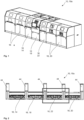
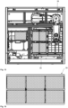
- Fig. 1 shows an embodiment of a system 10 according to the invention in an isometric view.
- the system 10 can be designed as a soldering system 10a and include several modules 16.
- the system 10 comprises at least five modules 16, whereby the first and last module 16 can each be further divided.
- the middle three modules 16 form a preheating module 14, a soldering or sintering module 18 and a soft cooling module 22.
- the soft cooling module is arranged between the soldering or sintering module 18 and the cooling module 20.
- the cooling module 20 forms the last module 16 of the system 10 in the embodiment shown.
- a discharge module can be connected downstream of the cooling module 20.
- the module 16 on the left in the illustration can therefore be designed as a loading module.
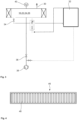
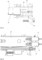
- Fig. 2 a sectional view of a further embodiment of a system 10 according to the invention is shown.
- the vacuum flat slides 44 can be seen between the individual modules 16.
- the housing is made of Fig. 1 not shown.
- This embodiment shows four modules 16, a preheating module 14, a soldering or sintering module 18, a soft cooling module 22 and a cooling module 20.
- the modules 16 are arranged one after the other in the order described.
- the soft cooling module 16 is spatially separated from the soldering or sintering module 18 and the cooling module 20 with a vacuum flat slide 44.
- a heating plate can be arranged in the soft cooling module 16, wherein the heating plate can be cooled from below with cold gas, in particular nitrogen. This allows the electronic assemblies to cool down to just below the solder solidification temperature.
- Fig. 3 shows a circuit diagram of an embodiment of a system 10 according to the invention.
- the soft cooling module 22 can be designed as a pressure chamber 24 or as a vacuum chamber 26.
- a pressure relief valve 30 is arranged on the soft cooling module 22.
- the soft cooling module 22 is connected to a backing pump 38 via an evacuation valve 36.
- a gas collecting container 32 is provided for flushing the electronic assemblies and is connected to the soft cooling module 22 via an inlet valve 28.
- the gas collecting container can, for example, collect the gas, in particular nitrogen, with which the electronic assemblies in the soft cooling module 22 were flushed.
- the gas is cleaned before, after or in the gas collecting container 2 in order to then be fed back to the soft cooling module 22 via a supply line. This means the gas can be reused.
- the soft cooling module 22 includes a quick vent valve 34. The structure described allows an overpressure, a negative pressure or a vacuum in the soft cooling module 22 to be controlled.
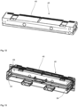
- Fig. 4 shows an embodiment of a cold trap 46.
- the cold trap 46 can be arranged in the process chamber of the soft cooling module 22.
- the cold trap 46 has ribs 46 in order to increase a cooling surface and to enable condensate to drip off.
- the cold trap 46 can have a drip tray (not shown) which is set up to collect the condensate.
- the cold trap 46 can also serve as a gas cooler to protect the downstream valves and the downstream pump technology.
- Fig. 5 is a circuit diagram of a further embodiment of an inventive Appendix 10 shown.
- a further pressure control valve 42 is arranged on the soft cooling module 22.
- this can have a connection to the exhaust air.
- an overpressure can be generated in the soft cooling module 22, whereby the overpressure can be, for example, less than 0.5 bar in order to avoid proof according to the Pressure Equipment Directive.
- the soft cooling module 22 can be designed according to the Pressure Equipment Directive and have an overpressure of, for example, 3 bar or more. Controlled temperature control down to just below the solder solidification temperature can take place via a heating and/or cooling device in the soft cooling module 22. In this way, contamination in the solder can be avoided, since these remain in the soft cooling module 22 before they have completely cooled down to room temperature in the downstream cooling module 20 and thus do not accumulate on the electronic assemblies.
- a flushing gas is therefore advantageously used in the soft cooling module 22, with which the contaminants are removed or flushed out directly from the soft cooling module 22.
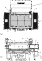
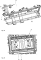
- Fig. 6 shows a top view of a process chamber 52.
- the process chamber 52 is preferably designed as a gas-tight sealable process chamber 52 and arranged in a module 16, which is designed as a soldering module 18.
- several electronic assemblies are arranged on a workpiece carrier 56.
- a heat source 50 shown in Fig. 7
- a cold trap 46 arranged in the process chamber 52.
- the process chamber 52 is a vacuum process chamber.
- a specific process atmosphere can be provided in the process chamber 52 by the heat source 50 and the cold trap 46.
- flows in the process atmosphere can arise solely through convection, which is generated by a temperature difference between the cold trap 46 and the heat source 50.
- Fig. 7 shows a sectional view of the process chamber 52 Fig. 6 .
- the heat source 50 is shown on the underside of the process chamber 52.
- the heat source 50 is therefore preferably located below the workpiece carrier 56.
- An additional heat source (not shown) can be arranged for additional heating of the process chamber 52.
- the cold area 72 protrudes as far as possible into the process chamber 52.
- the cold trap 46 results in less contamination of the modules 16 during the soldering process. This is achieved by collecting the condensate from the soldering paste and specifically directing it out of the system.
- Fig. 8 shows another view of the process chamber 52 Fig. 6 .
- the surfaces on which the remaining condensate evaporates are represented by the temperature control zones 76.
- targeted use of the vapor pressure of solvent can be exploited. Some solvents precipitate on the temperature control zones 76 because the vapor pressure is higher than at 100 ° C with a pressure of 950 bar.
- the residues of the solvent also evaporate for condensation on the cold surfaces, ie in the cold areas 72, of the cold trap 46 and are therefore specifically collected.
- the temperature control zone 76 the temperatures can be at 100 °C.
- the temperatures can be 150 ° C to 300 ° C.
- Fig. 9 shows a cold trap 46 with cooling fins 48.
- the cooling fins 48 can be arranged on the inner wall of the process chamber 52 and serve to increase the cooling surface. Furthermore, the cooling fins 48 can improve the dripping of the condensate.
- the illustration shows a view from the interior of the process chamber 52, with a workpiece carrier 56 being arranged on the floor of the process chamber 52.
- Fig. 10 shows a further embodiment of a cold trap 46 with cooling fins 48. Below the cooling fins 48, a collecting device 64 can be seen; this is designed to collect the condensate generated on the cold trap 46.
- Fig. 11 shows a side view of another cold trap 46.
- the direction of the dripping or the flow direction of the condensate is shown by the arrow directions.
- the collecting device 64 can be designed, for example, as a drip tray.
- the collected condensate flows via the collecting device 64 towards a collecting container 82. Continuous evacuation can be supported via a vacuum pump line.
- the condensate contains in particular solvents, unwanted deposits and/or contamination.
- Fig. 12 shows a possible cooling circuit in a cold trap 46, shown by the direction of the arrow.
- Fig. 13 shows a receiving element 69 for the cold trap 46 Fig. 12 .
- the cold trap 40 can therefore be mounted interchangeably.
- the cold trap 46 is inserted into the receiving element 69 from behind, in particular via guides 84 which are arranged on two opposite sides of the receiving element 69. In particular, thermal insulation is also arranged on the guides 84.
- the receiving element 69 is mounted directly on the process chamber 52 (not shown). Likewise, the receiving element 69 can form the process chamber 52 itself, whereby the cold trap 46 can be mounted directly on the process chamber 52.
- Fig. 14 shows a collecting device 64 of a cold trap 46.
- the collecting device 64 is designed as a drip tray, with the collected condensate being drained backwards into the receiving element 69 via an opening 65, in this embodiment designed as a slot.
- Fig. 15 shows a top view of a module 16 of the soldering system 10a with robot.
- the module 16 shown can in particular be the one in Fig. 1 represent module 16 shown on the far left, and in particular be designed as a loading station.
- the workpiece carriers 56 in particular are loaded with electronic assemblies 12, and in this embodiment this can be done via a robot arm 78.
- Fig. 16 shows an embodiment of a workpiece carrier 56. This is designed for six electronic assemblies 12. Such a workpiece carrier 56 is used in particular in a process chamber 52 as in Figs. 6 to 9 used.
- Fig. 17 shows a further embodiment of a cold trap 46.
- the cold trap 46 has a collecting device 64, which runs as an inclined plane on the underside of the cold trap 46.
- the collecting device 64 does not have a slot but rather individual openings 65 from which the condensate is drained out of the cold trap 46 and into the receiving element 69 (not shown).
- Fig. 18 shows an embodiment of a receiving element 69 for the cold trap 46 Fig. 17 .
- On the underside of the receiving element 69 several slopes 86 are arranged, via which the condensate can be directed out of the openings 56 of the cold trap 46.
- the condensate runs via the slopes 86 to an opening 88 and is discharged from the receiving element 69 via the opening 88.
- the receiving element 69 has two such openings 88, to which two slopes 86 each lead.
- the receiving element 69 forms a kind of receiving box for the cold trap.
- Fig. 19 shows a side view of the receiving element 69 with cold trap 46 the Figs. 17 and 18 . It can be seen that a pipe 60 is connected to the opening 88, which specifically removes the condensate. In other words, the process chamber 52 is connected via the pipeline 60. An opening of the pipeline 60, which communicates with the opening 88, is provided immediately adjacent to the cold trap 46. A heating sleeve 90 can be arranged around the pipeline 60.
- Some such construction with a receiving element 69 can also be referred to as an evacuation device 62.
- the evacuation device 62 can of course be designed differently than in Fig. 19 shown.
- Fig. 20 shows another view of the execution Fig. 19 . It can be seen that the receiving element 69 has two openings 88 on the underside, each of which is connected via a pipe 60.
- Fig. 21 shows a sectional view of the embodiment Fig. 19 .
- the cold trap 46 with the collecting device 64 in particular in the form of a collecting plate, is inserted into the receiving element 69 from one side.
- the cold trap 46 can be held guided in the receiving element 69 via guides 84.
- Fig. 22 shows a detailed view of the embodiment Fig. 20 .
- a heating element 92 is arranged on the underside of the receiving element 69, the connection 94 of which is also on the right side of the receiving element 69.
- This heating element 92 can, for example, form an additional heat source 54.
- Fig. 23 shows an isometric view of the receiving element 69 with opening element 69a.
- the opening element 69a is pivotally mounted on the receiving element 69.
- Fig. 24 shows a sectional view through a process chamber 52.
- a heating plate 96 is provided, which is provided with soft cooling 98.
- it can have a pivoting lid (not shown) which can be screwed to the process chamber 52. This allows the process chamber 52 be designed to be gas-tight.
- Fig. 25 shows another embodiment of a workpiece carrier 56.
- Fig. 26 shows another view of the embodiment Fig. 25 .
- the heating plate 96 can be seen directly below the receiving elements for the electronic assemblies 12 (not shown).
- the heating plate 96 can be designed as a contact plate in a sandwich construction.
- a cooling process can take place via thermal oil and/or a heating cable.
- Such a sandwich plate can form a controllable and heatable contact plate and can also be referred to as a soft cooling plate.
- heating conductors 98 inserted in a meandering shape are included in the heating plate 92.
- a thermocouple in particular a substrate thermocouple, may be included, which is, for example, arranged centrally and/or designed to be flexible.
Description
Die Erfindung betrifft eine Anlage zum Verbinden von elektronischen Baugruppen, insbesondere eine Löt- oder Sinteranlage mit einer Transportvorrichtung zum Transport der elektronischen Baugruppen durch die Anlage, umfassend mehrere, gasdicht abtrennbare Module zum Verbinden der elektronischen Baugruppen miteinander, wobei zumindest ein Modul als Löt- oder Sintermodul und ein Modul als Kühlmodul ausgebildet ist.The invention relates to a system for connecting electronic assemblies, in particular a soldering or sintering system with a transport device for transporting the electronic assemblies through the system, comprising several, gas-tight, separable modules for connecting the electronic assemblies to one another, with at least one module as a soldering or Sintering module and a module is designed as a cooling module.
Aus dem Stand der Technik sind eingangs genannte Anlagen zur Temperaturbehandlung von Bauteilen mit Gasdichte verschließbaren Kammern bzw. Modulen bekannt.The above-mentioned systems for the temperature treatment of components with gas-tight sealable chambers or modules are known from the prior art.
Eine derartige Anlage kann beispielsweise als eine Lötvorrichtung zum Herstellen einer Lötverbindung zwischen mehreren Bauteilen, insbesondere elektronischen Baugruppen, ausgebildet sein. Diese kann durch Erhitzen und Aufschmelzen von Lotmaterial, welches zwischen den zu verbindenden Bauteilen angeordnet ist, und/oder zum Überziehen eines Bauteils mit Lotmaterial für einen nachfolgenden Verbindungsprozess, ausgestaltet sein. In der Regel werden die Bauteile und das Lotmaterial, welches beispielsweise in Form von Lötplättchen, als Lotpaste oder als Lotpulver vorliegen kann, vor dem Einbringen in die Prozesskammer zu einem Stapel temporär zusammengefügt.Such a system can be designed, for example, as a soldering device for producing a soldered connection between several components, in particular electronic assemblies. This can be designed by heating and melting solder material, which is arranged between the components to be connected, and/or by covering a component with solder material for a subsequent connection process. As a rule, the components and the solder material, which can be in the form of solder plates, solder paste or solder powder, are temporarily assembled into a stack before being introduced into the process chamber.
Mithilfe einer derartigen Lötvorrichtung werden insbesondere großflächige Verbindungen hergestellt, bei denen beispielsweise Halbleiterbauelemente, Mikroelektronikbauteile oder Leistungshalbleiterchips, wie z. B. Transistoren oder Dioden auf Leiterplatten, IGBTs, MOSFETs oder Dioden auf metallisierte Keramiksubstrate oder sonstige Schaltungsträger gelötet bzw. miteinander verlötet werden, oder bei denen metallisierte Keramiksubstrate auf metallische Grundplatten und/oder Kühlkörper gelötet werden. Auch Leiterplatten, welche mit Kühlkörpern verbunden werden sollen, können in einer gattungsgemäßen Lötvorrichtung gelötet werden.With the help of such a soldering device, large-area connections are produced in particular, in which, for example, semiconductor components, microelectronic components or power semiconductor chips, such as. B. Transistors or diodes on circuit boards, IGBTs, MOSFETs or diodes on metallized ceramic substrates or other circuit carriers are soldered or soldered together, or in which metallized ceramic substrates are soldered to metallic base plates and/or heat sinks. Circuit boards that are to be connected to heat sinks can also be soldered in a generic soldering device.
Um ein optimales Lötergebnis zu erzielen, wird angestrebt, das aufgeschmolzene Lot zusammen mit den zu verbindenden Bauteilen kontrolliert über den Schmelzpunkt des Lotes zu erwärmen und anschließend kontrolliert unter den Erstarrungspunkt des Lotes abzukühlen, um die Bauteile lunkerfrei miteinander zu verbinden. Das Lot kann ein Weich- oder ein Hartlot sein, inbesondere ein Zinnlot, aber auch ein Silberlot, Messinglot oder Phosphorlot.In order to achieve an optimal soldering result, the aim is to heat the melted solder together with the components to be connected in a controlled manner above the melting point of the solder and then cool it in a controlled manner below the solidification point of the solder in order to connect the components together without voids. The solder can be a soft or hard solder, especially a tin solder, but also a silver solder, brass solder or phosphorus solder.
Das Herstellen von Lötverbindungen erfolgt in der Regel in einer von der Umgebung abgeschlossenen, insbesondere evakuierbaren Prozesskammer, in welcher zum Beispiel eine Basisplatte und eine Andruckplatte angeordnet sein können, zwischen denen eine das oder die Bauteile und das Lotmaterial umfassende Lötgruppe aufgenommen ist. Die Basisplatte und die Andruckplatte können zum Ausüben einer Presskraft auf die Lötgruppe relativ zueinander bezüglich ihres Abstandes verstellbar sein. Zugleich können die Andruckplatte und/oder die Basisplatte das Erhitzen und/oder das Abkühlen der Bauelemente und des Lotmaterials bewirken. Hierzu können die genannten Platten mit entsprechenden Wärmequellen und/oder Wärmesenken thermisch gekoppelt sein.The production of soldered connections usually takes place in a process chamber that is closed off from the environment and in particular can be evacuated, in which, for example, a base plate and a pressure plate can be arranged, between which a soldering group comprising the component or components and the solder material is accommodated. The base plate and the pressure plate can be adjustable in terms of their distance relative to one another in order to exert a pressing force on the soldering group. At the same time, the pressure plate and/or the base plate can cause the components and the solder material to be heated and/or cooled. For this purpose, the plates mentioned can be thermally coupled to corresponding heat sources and/or heat sinks.
Eine derartige Anlage kann auch als eine Sintervorrichtung zum Herstellen eines Werkstücks aus zumindest einer Komponente mittels Drucksintern, insbesondere mittels Niedertemperaturdrucksintern, ausgestaltet sein. Eine derartige Sintervorrichtung kann ein Oberwerkzeug und ein Unterwerkzeug, zwischen denen die zumindest eine Komponente aufgenommen ist, wobei das Oberwerkzeug und das Unterwerkzeug zum Aufbringen einer Presskraft auf das zu sinternde Werkstück relativ zueinander verstellbar sind, und zumindest eine Heizvorrichtung zum Erwärmen des zu sinternden Werkstücks umfassen.Such a system can also be designed as a sintering device for producing a workpiece from at least one component using pressure sintering, in particular using low-temperature pressure sintering. Such a sintering device can have an upper tool and a lower tool, between which the at least one component is accommodated, the upper tool and the lower tool being adjustable relative to one another for applying a pressing force to the workpiece to be sintered, and at least one heating device for heating the workpiece to be sintered .
In derartigen Sintervorrichtungen kann unter der Einwirkung von Hitze und Druck aus einem sogenannten Grünkörper, der aus einem fein- oder grobkörnigen Stoff oder Stoffgemisch besteht, ein festes Werkstück erzeugt werden. Neben dem Verpressen und Verdichten des Sintermaterials werden dabei die kontaktierten Flächen der Verbindungspartner mechanisch, thermisch und ggf. elektrisch verbunden. Der hier betrachtete Einsatz dient insbesondere zum mechanischen und elektrisch und/oder thermisch leitenden Verbinden zweier Bauteile, insbesondere elektrischer Halbleiterbauteile wie Hochleistungsschaltelemente oder Halbleiterbaugruppen und einem Grundkörper, in der Regel einer Platine, insbesondere eines DCBs/AMB'S Leadframes (Direct Copper Bonded / Active Metal Braze auf einem metallischen Leitungsträger bzw. Anschluss-Rahmens), einem Kühlkörper oder dergleichen.In such sintering devices, a solid workpiece can be produced under the influence of heat and pressure from a so-called green body, which consists of a fine- or coarse-grained substance or mixture of substances. In addition to pressing and compacting the sintered material, the contacted surfaces of the connection partners are connected mechanically, thermally and, if necessary, electrically. The insert considered here is used in particular for the mechanical and electrical and/or thermally conductive connection of two components, in particular electrical semiconductor components such as high-performance switching elements or semiconductor assemblies and a base body, usually a circuit board, in particular a DCB/AMB'S lead frame (Direct Copper Bonded/Active Metal Braze on a metallic cable carrier or connection frame), a heat sink or the like.
Weiterhin können bei einer Variante des Drucksinterns, dem NiedertemperaturDrucksintern, zwei oder mehr Bauelemente, insbesondere elektronische Bauelemente und Substrate, mittels eines Fügewerkstoffs miteinander, insbesondere elektrisch und/oder thermisch leitend, verbunden werden, wobei hierbei der verbindende Fügewerkstoff gesintert wird. Eine entsprechende Vorrichtung und ein Verfahren sind beispielsweise aus der
Weitere Anlagen können als automatischen Sinter- oder Lötanlagen, insbesondere automatischen Mehrkammer-Anlagen mit mehreren Prozesskammern, ausgebildet sein. Diese umfassen zumindest eine Kammer bzw. ein Modul zum elektrischen und/oder thermischen Verbinden eines elektrischen Bauteils mit einer weiteren Bauteilgruppe, einer elektrischen Platine oder DCBs/AMB'S Leadframes oder einem Kühlkörper.Other systems can be designed as automatic sintering or soldering systems, in particular automatic multi-chamber systems with several process chambers. These include at least one chamber or a module for electrically and/or thermally connecting an electrical component to another component group, an electrical circuit board or DCBs/AMB'S leadframes or a heat sink.
Unter dem Begriff "Bauteile" können allgemein elektronische Baugruppen, Schaltungsträger, Substrate, Substratträger, Grundplatten, Werkstückträger, Montageträger oder dergleichen aus Metall, Keramik, Kunststoff oder anderen Materialien oder beliebigen Materialkombinationen sowie darauf zu befestigende Bauelemente wie Leistungshalbleiterchips, (Halbleiter-) Baugruppen oder dergleichen verstanden werden.The term “components” generally includes electronic assemblies, circuit carriers, substrates, substrate carriers, base plates, workpiece carriers, assembly carriers or the like made of metal, ceramic, plastic or other materials or any combination of materials, as well as components to be fastened thereon such as power semiconductor chips, (semiconductor) assemblies or the like.
Oftmals werden Werkstückträger verwendet, welche mehrere Bauteile bzw. Bauteilgruppen zugleich aufnehmen können, wodurch die Handhabung vereinfachen und die Durchsatzraten erhöht werden kann.Workpiece carriers are often used that can accommodate several components or groups of components at the same time, which can simplify handling and increase throughput rates.
Derartige Anlagen können zumindest eine gasdicht verschließbare Prozesskammer aufweisen, in welcher die Bauteile während der Temperaturbehandlung aufgenommen sind. In dieser Prozesskammer kann eine spezifische Prozessatmosphäre bereitgestellt werden, die unerwünschte chemische Reaktionen, insbesondere eine Oxidation von metallischen Oberflächen des Werkstücks, reduziert oder verhindert, und/oder gewünschte chemische Reaktionen auslöst, begünstigt oder katalysiert. In der Prozessatmosphäre kann beispielsweise der relative Sauerstoffgehalt reduziert werden, beispielsweise auf einen Sauerstoffgehalt von 0,005 % bis 0,3 %. Hierfür kann beispielsweise ein Inertgas wie Stickstoff (N2) in die Prozesskammer eingeleitet werden. Die Prozessatmosphäre kann auch ein Reduktionsmittel, z. B. Methansäure (CH2O2) oder Stickstoff und Wasserstoff (N/H) beinhaltendes Formiergas umfassen.Such systems can have at least one process chamber that can be closed in a gas-tight manner and in which the components are accommodated during the temperature treatment. A specific process atmosphere can be provided in this process chamber, which reduces or prevents undesirable chemical reactions, in particular oxidation of metallic surfaces of the workpiece, and/or triggers, promotes or catalyzes desired chemical reactions. In the process atmosphere, for example, the relative oxygen content can be reduced, for example to an oxygen content of 0.005% to 0.3%. For this purpose, for example, an inert gas such as nitrogen (N 2 ) can be introduced into the process chamber. The process atmosphere can also contain a reducing agent, e.g. B. methanoic acid (CH 2 O 2 ) or nitrogen and hydrogen (N / H) containing forming gas.
Das Bereitstellen der Prozessatmosphäre kann auch eine Beeinflussung der Druckverhältnisse, d.h. das Erzeugen eines Überdrucks oder eines Unterdrucks umfassen.Providing the process atmosphere can also include influencing the pressure conditions, i.e. generating an overpressure or a negative pressure.
Häufig umfassen derartige Anlagen mehrere Prozesskammern, in denen die Bauteile unterschiedlichen Prozessbedingungen oder Prozessatmosphären ausgesetzt sein können. So kann beispielsweise in einer ersten Prozesskammer ein Temperieren der Bauteile oder Baugruppen auf Temperaturen unterhalb der Schmelztemperatur des Lotmaterials, in einer zweiten Prozesskammer ein Erwärmen auf die Löttemperatur und in einer dritten Prozesskammer ein kontrolliertes Abkühlen erfolgen, wobei jeweils die Eigenschaften der Prozessatmosphäre von Prozesskammer zu Prozesskammer variieren können oder auch während der Verweildauer in einer jeweiligen Kammer über die Zeit verändert werden können.Such systems often include several process chambers in which the components can be exposed to different process conditions or process atmospheres. For example, in a first process chamber the components or assemblies can be tempered to temperatures below the melting temperature of the solder material, in a second process chamber they can be heated to the soldering temperature and in a third process chamber there can be controlled cooling, with the properties of the process atmosphere changing from process chamber to process chamber can vary or can also be changed over time during the time spent in a respective chamber.
Aufgrund der abgeschlossenen Module bzw. Prozesskammern ruhen die Bauteile, bzw. Werkstückträger, in denen eine Anzahl von Bauteilen simultan miteinander verbunden werden, innerhalb der Module in einem sogenannten ruhenden Prozess im Gegensatz zu einem Fließprozess, der bei nicht-abgeschlossenen Modulen bzw. Prozesskammern möglich ist. Um weiterhin eine Fließfertigung zu gewährleisten, können mehrere Bauteile eines Fließfertigungstransports in einem Werkstückträger angeordnet, d.h. geclustert werden, in einem schrittweise stehenden Prozess durch die Anlage geführt, und hiernach wieder vereinzelt in eine weitere Fließfertigung entlassen werden. Somit kann auch eine, schrittweise stehend geführte Anlage in einem kontinuierlichen Fließfertigungsprozess eingebunden werden. Das Clustern und Vereinzeln kann automatisiert erfolgen, wobei eine erleichterte Qualitätskontrolle und ggf. das Hinzufügen von Abdeckungen und dergleichen, beispielsweise für einen Sinterprozess, möglich ist.Due to the closed modules or process chambers, the components or workpiece carriers, in which a number of components are connected to one another simultaneously, rest within the modules in a so-called resting process in contrast to a flow process, which is possible with non-closed modules or process chambers is. In order to continue to ensure flow production, several components of a flow production transport can be arranged in a workpiece carrier, i.e. clustered, guided through the system in a step-by-step process, and then individually released into another flow production. This means that a step-by-step, standing system can also be integrated into a continuous flow production process. The clustering and separation can be carried out automatically, with easier quality control and, if necessary, the addition of covers and the like, for example for a sintering process, being possible.
Beim Erwärmen des Lotmaterials oder des Fügewerkstoffs können Bestandteile daraus, z.B. Bindemittel oder Füllstoffe, durch Sublimation oder Verdampfen in die Prozessatmosphäre entweichen, was zu einer ungewollten Verschmutzung oder Kontamination von Bauteilen, der Prozesskammer, darin aufgenommener Komponenten der Anlage oder von nachgeordneten Einrichtungen wie Pumpen, Ventilen oder Rohren führen kann. Auch andere Substanzen wie Flussmittel, Haftmittel zur Fixierung der Bauteile oder Bestandteile der zu verbindenden Bauteile, sowie Reaktionsprodukte der genannten Bestandteile und Atmosphären können zu solchen Verunreinigungen führen.When the solder material or the joining material is heated, components thereof, e.g. binders or fillers, can escape into the process atmosphere through sublimation or evaporation, which leads to unwanted contamination or contamination of components, the process chamber, components of the system contained therein or of downstream devices such as pumps, valves or pipes. Other substances such as fluxes, adhesives for fixing the components or components of the components to be connected, as well as reaction products of the components and atmospheres mentioned can also lead to such contamination.
Bei automatischen Mehrkammer-Anlagen bzw. einer aus Mehrfachmodulen in Modulbauweise bestehenden Anlage kann ein Transport dieser Werkstückträger zwischen den verschieden Modulen bzw. Kammern mit Hilfe von auch als Laufleisten bezeichneten Transportvorrichtungen erfolgen. Die einzelnen Kammern können jeweils mit Vakuumflachschiebern voneinander getrennt sein, um individuell einstellbare Prozessatmosphären bereitzustellen. Diese Vakuumflachschieber bzw. Schleusen sind üblicherweise gekühlt, um Dichtungen vor Hitzeschäden zu schützen.In automatic multi-chamber systems or a system consisting of multiple modules in a modular design, these workpiece carriers can be transported between the different modules or chambers with the help of transport devices also known as running strips. The individual chambers can be separated from each other with vacuum flat slides, to provide individually adjustable process atmospheres. These vacuum flat valves or locks are usually cooled to protect seals from heat damage.
So ist aus der
In der
Die
Die
Bei bekannten Anlagen bzw. Verfahren besteht allgemein das Problem, dass Verunreinigungen, insbesondere durch den Lötzusatz und die Atmosphäre, nach der Abkühlung auf den Baugruppen bzw. Bauteilen und/oder in zumindest einer Kammer zurückbleiben. Diese Verunreinigungen führen zu Qualitätseinbußen beim Lötvorgang und können beispielsweise Lunker hervorrufen.In known systems or methods there is generally the problem that contamination, in particular due to the soldering additive and the atmosphere, remains on the assemblies or components and/or in at least one chamber after cooling. These contaminants lead to a loss of quality during the soldering process and can, for example, cause voids.
Aufgabe der Erfindung ist es daher, eine Anlage vorzuschlagen, mit welcher Ablagerungen von unerwünschten Substanzen in den unterschiedlichen Modulen sowie an den Lötstellen reduziert oder vermieden werden können.The object of the invention is therefore to propose a system with which deposits of undesirable substances in the different modules and at the soldering points can be reduced or avoided.
Weiterhin ist die Aufgabe der Erfindung, eine Anlage zu schaffen, bei welcher die Entstehung von Ablagerungen von unerwünschten Substanzen in den Modulen und am Lötgut reduziert oder vermieden wird. Dabei ist es Aufgabe der Erfindung, insbesondere in geschlossenen Modulen in stehenden Prozessen und unter gesteuertem Atmosphäreneinfluss eine Verweilzeit von unerwünschtem Kondensat an den Wänden des Moduls zu minimieren.Furthermore, the object of the invention is to create a system in which the formation of deposits of undesirable substances in the modules and on the soldered material is reduced or avoided. It is the object of the invention to minimize the residence time of unwanted condensate on the walls of the module, particularly in closed modules in stationary processes and under controlled atmospheric influence.
Diese Aufgabe wird durch eine Anlage nach dem unabhängigen Anspruch 1 gelöst. Vorteilhafte Weiterentwicklungen der Erfindung sind Gegenstand der Unteransprüche.This task is solved by a system according to
Gegenstand der Erfindung ist eine Lot- und/oder Sinteranlage zum Verbinden von elektronischen Baugruppen nach Anspruch 1 mit einer Transportvorrichtung zum Transport der elektronischen Baugruppen durch die Anlage, umfassend mehrere, Gasdichte abtrennbare Module zum Verbinden der elektronischen Baugruppen miteinander, wobei zumindest ein Modul als Löt- und/oder Sintermodul und ein Modul als Kühlmodul ausgebildet ist.The subject of the invention is a soldering and/or sintering system for connecting electronic assemblies according to
Es wird vorgeschlagen, dass zwischen dem Löt- oder Sintermodul und dem Kühlmodul ein weiteres Modul angeordnet ist, dass als Softabkühlmodul, zur Abkühlung zwischen einer Prozesstemperatur des Löt- oder Sintermodul und einer Zwischentemperatur, insbesondere unter einer Loterstarrungstemperatur, ausgebildet ist. Das Softabkühlmodul ist daher dem Kühlmodul vorgeschaltet, wodurch zunächst eine Abkühlung auf eine gewünschte bzw. erzielte Temperatur, die insbesondere ungleich der Raumtemperatur ist, erfolgen kann. Dabei liegt die Temperatur, bis zu welcher zumindest das Lotmaterial in der Softabkühlkammer abgekühlt wird, knapp unterhalb der Loterstarrungstemperatur. Verunreinigungen durch den Lötvorgang, insbesondere Lotpastenrückstände, am Bauteil bzw. an der Baugruppe können dadurch vermieden werden, da sich die Verunreinigungen nicht an dem Lotgut absetzen bzw. an den elektronischen Baugruppen kondensieren. Insbesondere können ein Kondensieren und Ablagern der Lotpastenrückstände und/oder aus der Atmosphäre am Bauteil bzw. der Baugruppe sowie in dem Modul selbst zumindest reduziert, insbesondere vermieden werden. Dies wird beispielsweise dadurch erreicht, dass die Lotpastenrückstände im Bereich des Softabkühlmoduls gezielt zur Kondensation gebracht werden und sich bevorzugt dort ablagern. Daher können die Verunreinigungen vor dem endgültigen Abkühlen direkt aus dem Softabkühlmodul entfernt werden und gelangen bevorzugt nicht in das nachgeschaltete Kühlmodul. Ein Anhaften an den Bauteil bzw. Baugruppen kann dadurch vermieden werden, wodurch die Qualität der Lötverbindung verbessert werden kann. Insgesamt kann eine Anlage, insbesondere eine Lötanlage, mit reduzierter Verschmutzung der einzelnen Kammern des Lötprozesses, insbesondere bei der Verwendung von Lötpaste und/oder HCOOH, bereitgestellt werden. Im Zusammenhang mit der dargestellten Erfindung können die Begriffe Kammer und Modul synonym verwendet werden. In dem Lötmodul kann eine Temperatur von beispielsweise 250 °C vorliegen. In dem Kühlmodul werden die elektronischen Baugruppen bevorzugt auf Raumtemperatur, d. h. 20 °C, abgekühlt. Durch das dazwischenliegende Softabkühlmodul kann eine sogenannte erste, softe Abkühlung erfolgen. Diese liegt in einem Bereich knapp unter der Loterstarrungstemperatur. Die Loterstarrungstemperatur liegt im Bereich von 150 °C bis 220 °C. Das Lot kann insbesondere ein Zinn- oder Silberlot (AG) sein. In dem Softabkühlmodul erfolgt daher eine Abkühlung von oberhalb der Liquidustemperatur von beispielsweise 250° auf unter die Solidustemperatur, d.h. der Loterstarrungstemperatur, d.h. eine geführte Abkühlung von oben durch das Schmelzintervall. Vor dem Lötmodul kann ein weiteres Modul angeordnet sein, beispielsweise ein Vorheizmodul und/oder ein Einschleusmodul zum Einbringen der elektronischen Baugruppen in die Anlage.It is proposed that a further module is arranged between the soldering or sintering module and the cooling module, which is designed as a soft cooling module for cooling between a process temperature of the soldering or sintering module and an intermediate temperature, in particular below a solder solidification temperature. The soft cooling module is therefore connected upstream of the cooling module, whereby cooling can initially take place to a desired or achieved temperature, which in particular is not equal to the room temperature. The temperature to which at least the solder material is cooled in the soft cooling chamber is just below the solder solidification temperature. impurities Due to the soldering process, in particular solder paste residues, on the component or assembly can be avoided because the contaminants do not settle on the solder or condense on the electronic assemblies. In particular, condensation and deposition of the solder paste residues and/or from the atmosphere on the component or assembly as well as in the module itself can be at least reduced, in particular avoided. This is achieved, for example, by specifically causing the solder paste residues to condense in the area of the soft cooling module and preferably depositing there. Therefore, the contaminants can be removed directly from the soft cooling module before the final cooling and preferably do not reach the downstream cooling module. Sticking to the component or assemblies can thereby be avoided, which can improve the quality of the solder connection. Overall, a system, in particular a soldering system, can be provided with reduced contamination of the individual chambers of the soldering process, especially when using solder paste and/or HCOOH. In connection with the invention presented, the terms chamber and module can be used synonymously. The soldering module can have a temperature of, for example, 250 °C. In the cooling module, the electronic assemblies are preferably cooled to room temperature, ie 20 °C. The intermediate soft cooling module allows a so-called first, soft cooling to take place. This is in a range just below the solder solidification temperature. The solder solidification temperature is in the range from 150 °C to 220 °C. The solder can in particular be a tin or silver solder (AG). In the soft cooling module, cooling takes place from above the liquidus temperature of, for example, 250° to below the solidus temperature, ie the solder solidification temperature, ie guided cooling from above through the melting interval. A further module can be arranged in front of the soldering module, for example a preheating module and/or an introduction module for introducing the electronic assemblies into the system.
Um den Montage- sowie Konstruktionsaufwand so gering wie möglich zu halten, kann es vorteilhaft sein, wenn das Softabkühlmodul nicht unter die Druckgeräterichtlinie Richtlinie 2014/68/EU fällt. Als Druckgeräte im Sinne dieser Richtlinie 2014/68/EU gelten beispielsweise Behälter, Rohrleitungen und druckhaltende Ausrüstungsteile bzw. Ausrüstungsteile mit Sicherheitsfunktion mit einem inneren Überdruck von mehr als 0,5 bar. In dem Softabkühlmodul kann daher bevorzugt ein Überdruck von kleiner oder gleich 0,5 bar vorliegen. Das Volumen der Kammer kann beispielhaft bei ca. 50 Liter oder darüber liegen, andere Volumina sind ebenso denkbar. So kann beispielsweise eine interne Fertigungskontrolle entfallen, wodurch der Zeitaufwand reduziert wird. Insbesondere kann ein Druckfluten auf 0,5 barü erfolgen, wobei anschließend dieser Druck gehalten wird. Der Wert 0,5 barü bedeutet ein Überdruck von 0,5 bar über dem atmosphärischen Druck.In order to keep the assembly and construction effort as low as possible, it can be advantageous if the soft cooling module does not fall under the Pressure Equipment Directive Directive 2014/68/EU. As pressure equipment within the meaning of this directive For example, 2014/68/EU applies to containers, pipelines and pressure-retaining equipment or equipment with a safety function with an internal overpressure of more than 0.5 bar. An excess pressure of less than or equal to 0.5 bar can therefore preferably be present in the soft cooling module. The volume of the chamber can be around 50 liters or more, for example, other volumes are also conceivable. For example, internal production control can be eliminated, which reduces the time required. In particular, pressure flooding can take place to 0.5 barg, with this pressure then being maintained. The value 0.5 barg means an excess pressure of 0.5 bar above atmospheric pressure.
Die Temperatur in dem Softabkühlmodul kann gehalten oder erhöht werden, bis der gewünschte Überdruck in dem Softabkühlmodul aufgebaut ist. Das Heizen in der Softabkühlkammer kann allgemein über Konvektion, beispielweise durch Gas, über Kontakterwärmung und/oder über Strahlungserwärmung, insbesondere IR-Licht erfolgen.The temperature in the soft cooling module can be maintained or increased until the desired excess pressure is built up in the soft cooling module. Heating in the soft cooling chamber can generally take place via convection, for example by gas, via contact heating and/or via radiation heating, in particular IR light.
Die Anlage umfasst eine übergeordnete Steuerung. Diese kann zur Steuerung aller Module der Anlage dienen. In einer bevorzugten Ausführungsform kann zumindest ein Modul einen eigenen primären Steuerkreis und/oder Sicherheitskreis aufweisen. Dadurch können einzelne Module und/oder einzelne Arbeitsschritte ausgetauscht werden, ohne dass eine komplette Neuprogrammierung der übergeordneten Steuerung erfolgen muss. Insbesondere kann mehr als ein Modul, insbesondere zwei oder mehr Module, einen eigenen Steuerkreis und/oder Sicherheitskreis aufweisen.The system includes a higher-level control system. This can be used to control all modules in the system. In a preferred embodiment, at least one module can have its own primary control circuit and/or safety circuit. This means that individual modules and/or individual work steps can be replaced without having to completely reprogram the higher-level control system. In particular, more than one module, in particular two or more modules, can have their own control circuit and/or safety circuit.
In einer bevorzugten Ausführungsform kann das Softabkühlmodul eingerichtet sein, einen Überdruck einer Prozessatmosphäre von 1 bar, insbesondere bis 4,5 bar oder auch mehr, bereitzustellen. Bevorzugt kann in dem Softabkühlmodul der Überdruck von -1 bar (Vakuum) aus einer davor angeordneten Kammer über 1 bar, insbesondere bis 3,5 bar, erhöht werden. Andere Drücke sind ebenso denkbar. Insgesamt sind Druckbereiche sinnvoll, für die das bereits bestehende System der Anlage ausgebildet ist.In a preferred embodiment, the soft cooling module can be set up to provide an overpressure of a process atmosphere of 1 bar, in particular up to 4.5 bar or even more. Preferably, in the soft cooling module, the excess pressure of -1 bar (vacuum) from a chamber arranged in front of it can be increased to over 1 bar, in particular up to 3.5 bar. Other pressures are also conceivable. Overall, pressure ranges for which the existing system of the system is designed make sense.
In einer bevorzugten Ausführungsform kann das Softabkühlmodul eingerichtet sein, einen Unterdruck unter 1 bar, insbesondere ein Vakuum von -1 bar, bereitzustellen. Dadurch kann beispielsweise ein Vakuumdurchlauf in der Lötanlage erfolgen, der ebenfalls zu einer reduzierten Verschmutzung der Kammern beim Lötprozess, insbesondere mit Paste und/oder Ameisensäure, HCOOH, führt.In a preferred embodiment, the soft cooling module can be set up to provide a negative pressure below 1 bar, in particular a vacuum of -1 bar. This allows, for example, a vacuum run in the soldering system, which also leads to reduced contamination of the chambers during the soldering process, in particular with paste and/or formic acid, HCOOH.
In einer bevorzugten Ausführungsform kann das Softabkühlmodul als Überdrucckammer und/oder Vakuumkammer ausgebildet sein. Das Softabkühlmodul kann mit Vakuumflachschiebern von benachbarten Modulen getrennt sein, um die Überruckkammer bzw. Vakuumkammer auszubilden. Diese Vakuumflachschieber bzw. Schleusen können gekühlt sein, um daran angeordnete Dichtungen vor Hitzeschäden zu schützen.In a preferred embodiment, the soft cooling module can be designed as a pressure chamber and/or vacuum chamber. The soft cooling module can be separated from neighboring modules with vacuum flat slides in order to form the pressure chamber or vacuum chamber. These vacuum flat slides or locks can be cooled in order to protect seals arranged on them from heat damage.
Erfindungsgemäß ist in dem Softabkühlmodul eine Heiz- und/oder eine Kühlvorrichtung zur gesteuerten Temperierung und Abkühlung der elektronischen Baugruppen von 500 °C oder darunter auf eine Temperatur unter der Loterstarrungstemperatur, insbesondere auf 150 °C oder weniger, umfasst, die insbesondere als heiz- und/oder kühlbare Kontaktplatte ausgeformt ist. Ebenso erfolgt eine Temperierung und Abkühlung der elektronischen Baugruppen von einer anderen Temperatur, beispielsweise 250 °C, auf eine Temperatur unter der Loterstarrungstemperatur.According to the invention, the soft cooling module includes a heating and/or a cooling device for controlled temperature control and cooling of the electronic assemblies from 500 ° C or below to a temperature below the solder solidification temperature, in particular to 150 ° C or less, which is in particular as heating and / or coolable contact plate is formed. The electronic assemblies are also tempered and cooled from a different temperature, for example 250 ° C, to a temperature below the solder solidification temperature.
In einer bevorzugten Ausführungsform kann die Kontaktplatte als Heizplatte ausgeführt sein, und eine Abkühlvorrichtung als Gaskühlvorrichtung zur Abkühlung der Kontaktplatte mittels Gasströmung, bevorzugt Stickstoffgasströmung, insbesondere Heliumgasströmung, von einer den elektronischen Baugruppen abgewandten Seite der Heizplatte ausgeführt sein. Dadurch kann ein gesteuertes Abkühlen vorteilhafterweise erreicht werden. Insbesondere kann nach dem Aufbau des gewünschten Drucks ein Abkühlen der Heizplatten über kaltes Stickstoffgas erfolgen. Das Gas kann beispielsweise von unten an die zumindest eine abgeschaltete Heizplatte angeströmt werden. In einer anderen Ausführungsform kann über einen gewählten Abstand zwischen der Heizplatte und den elektronischen Bauteilen eine gewünschte Abkühlung erzielt werden. In allen Fällen erfolgt bevorzugt eine Abkühlung des Lotes bis unterhalb des Erstarrungspunktes. Anschließend können die elektronischen Baugruppen aus dem Softabkühlmodul in das daran anschließende Kühlmodul gefördert werden.In a preferred embodiment, the contact plate can be designed as a heating plate, and a cooling device can be designed as a gas cooling device for cooling the contact plate by means of gas flow, preferably nitrogen gas flow, in particular helium gas flow, from a side of the heating plate facing away from the electronic assemblies. This allows controlled cooling to be advantageously achieved. In particular, after the desired pressure has been built up, the heating plates can be cooled using cold nitrogen gas. The gas can, for example, flow from below onto the at least one switched off heating plate. In another embodiment, the desired cooling can be achieved via a selected distance between the heating plate and the electronic components. In all cases, the solder is preferably cooled down to below the solidification point. The electronic assemblies can then be conveyed from the soft cooling module into the adjoining cooling module.
Die zumindest eine Heizplatte kann insbesondere aus Aluminium und/oder Kupfer ausgebildet sein. Bevorzugt ist die Heizplatte aus Kupfer ausgebildet.The at least one heating plate can in particular be made of aluminum and/or copper. The heating plate is preferably made of copper.
In einer bevorzugten Ausführungsform kann die Kontaktplatte in Sandwichbauweise ausgebildet sein. Bevorzugt kann dabei ein Kühlvorgang über Thermoöl erfolgen. Insbesondere kann ein Heizvorgang über ein Heizkabel erfolgen. Eine derartige Sandwichplatte kann eine steuerbare, insbesondere heizbare, Kontaktplatte ausbilden und auch als Softkühlplatte bezeichnet werden. Die Kontaktplatte kann mäanderförmig eingelegte Heizleiter, insbesondere in Form zumindest eines Rohrprofils, umfassen. Weiterhin kann ein Thermoelement, insbesondere ein Substratthermoelement, umfasst sein, das beispielsweise mittig angeordnet und/oder flexibel ausgebildet ist. Die Kontaktplatte kann über ein Hubeinheitensystem mit druckgeregelter Vakuum-Flüssigkeitsdurchführung gesteuert, insbesondere motorisch gesteuert, werden. In einer beispielhaften Ausführungsform können weiterhin ein Ölthermostat, ein Ausdehnungsbehälter, zumindest ein Sicherheitsventil und/oder eine magnetgekoppelte Thermalpumpe umfasst sein. Es kann eine Einmalbefüllung mit Thermoöl erfolgen. Mit der Kühlplatte kann beispielsweise eine Öltemperatur von kleiner oder gleich 185 °C in dem Softabkühlmodel erreicht werden. Dies erfolgt beispielsweise über einen verstärkten wassergekühlten Wärmetauscher als Ölkühler. Die Ölmenge kann beispielsweise über eine doppelte Mantelführung erfasst werden. Insbesondere kann das Thermostat autark arbeiten und/oder Startsignale und Temperaturvorgaben können über eine speicherprogrammierbare Steuerung (SPS) erfolgen. Insbesondere ist aus Praxisgründen eine Wassertemperatur von 16°C bei 35 l/min vorteilhaft.In a preferred embodiment, the contact plate can be designed in a sandwich construction. A cooling process can preferably take place using thermal oil. In particular, a heating process can take place via a heating cable. Such a sandwich plate can form a controllable, in particular heatable, contact plate and can also be referred to as a soft cooling plate. The contact plate can include heating conductors inserted in a meandering shape, in particular in the form of at least one tubular profile. Furthermore, a thermocouple, in particular a substrate thermocouple, may be included, which is, for example, arranged centrally and/or designed to be flexible. The contact plate can be controlled, in particular motor-controlled, via a lifting unit system with a pressure-controlled vacuum-liquid feedthrough. In an exemplary embodiment, an oil thermostat, an expansion tank, at least one safety valve and/or a magnetically coupled thermal pump may also be included. It can be filled once with thermal oil. With the cooling plate, for example, an oil temperature of less than or equal to 185 °C can be achieved in the soft cooling model. This is done, for example, using a reinforced water-cooled heat exchanger as an oil cooler. The amount of oil can be recorded, for example, via a double jacket guide. In particular, the thermostat can work autonomously and/or start signals and temperature specifications can be provided via a programmable logic controller (PLC). For practical reasons, a water temperature of 16°C at 35 l/min is particularly advantageous.
In einer bevorzugten Ausführungsform kann die Kontaktplatte mechanisch bewegbar sein, insbesondere mit den elektronischen Baugruppen kontaktierbar und beabstandbar sein und/oder die Kontaktplatte kann einen bevorzugt mäanderförmig ausgeführten Gasrechen umfassen. Der Gasrechen kann beispielsweise als N2-Gasrechen für die Softkühlung unter der zumindest einen Heizplatte angeordnet sein.In a preferred embodiment, the contact plate can be mechanically movable, in particular contactable and spaced apart with the electronic assemblies, and/or the contact plate can comprise a gas rake, preferably designed in a meandering shape. The gas rake can, for example, be arranged as an N2 gas rake for soft cooling under the at least one heating plate.
Erfindungsgemäß ist in dem Softabkühlmodul eine Gasspülvorrichtung zum Spülen der elektronischen Baugruppen, insbesondere mit kaltem Gas, bevorzugt mit kaltem Stickstoffgas, umfasst. Durch die Gasspülvorrichtung können vorteilhafterweise Verunreinigungen aus dem Lötzusatz und/oder der Atmosphäre direkt aus den Softabkühlmodul und damit von den elektronischen Baugruppen weggeleitet werden.According to the invention, in the soft cooling module there is a gas flushing device for flushing the electronic assemblies, in particular with cold gas, preferably with cold nitrogen gas. The gas purging device can advantageously direct contaminants from the soldering additive and/or the atmosphere directly away from the soft cooling module and thus away from the electronic assemblies.
In einer bevorzugten Ausführungsform kann an dem Softabkühlmodul ein Einlassventil zum Einlass des Gases in eine Prozesskammer des Softabkühlmoduls umfasst sein. Dadurch kann eine gewünschte Menge reinen Gases dem Softabkühlmodul direkt zugeführt werden. Insbesondere kann ebenso ein Auslassventil an dem Softabkühlmodul angeordnet sein, um auch eine gewünschte Menge an (verunreinigtem) Gas aus dem Softabkühlmodul abzuleiten. Dadurch kann der Druck innerhalb des Softabkühlmoduls direkt gesteuert werden. Insbesondere kann durch die gezielte Ableitung des Gases eine Ausleitung von Verunreinigungen an dem Softabkühlmodul erfolgen. Diese Verunreinigungen gelangen daher vorteilhafterweise nicht in das nachgeschaltete Kühlmodul und werden so frühzeitig vor der endgültigen Abkühlung der elektronischen Bauteilen bzw. Lötstellen von den Lötstellen entfernt.In a preferred embodiment, an inlet valve for inlet of the gas into a process chamber of the soft cooling module can be included on the soft cooling module. This means that a desired amount of pure gas can be supplied directly to the soft cooling module. In particular, an outlet valve can also be arranged on the soft cooling module in order to also drain a desired amount of (contaminated) gas from the soft cooling module. This allows the pressure within the soft cooling module to be controlled directly. In particular, the targeted discharge of the gas can result in the removal of contaminants from the soft cooling module. These contaminants therefore advantageously do not reach the downstream cooling module and are thus removed from the soldering points early before the electronic components or soldering points are finally cooled down.
In einer bevorzugten Ausführungsform kann außerhalb einer Prozesskammer des Softabkühlmoduls ein Gasauffangbehälter umfasst sein, der mit dem Einlassventil verbunden und zur Aufnahme des aus der Prozesskammer des Softabkühlmoduls ausgeleiteten Gases ausgebildet ist. Der Gasauffangbehälter kann beispielsweise als Pufferspeicher und Vorratstank für ein Reinigungs- und/oder Kühlgas dienen, wobei dies nicht eingrenzend ist. In, vor oder nach diesem Gasauffangbehälter kann eine Reinigungseinrichtung zur Reinigung des aus dem Softabkühlmodul abgeleiteten Gases angeordnet sein. Folglich kann das Gas wiederverwendet werden, wodurch ein nachhaltiger Prozess sowie eine nachhaltige Anlage bereitgestellt werden können.In a preferred embodiment, a gas collecting container can be included outside a process chamber of the soft cooling module, which is connected to the inlet valve and is designed to receive the gas discharged from the process chamber of the soft cooling module. The gas collecting container can, for example, serve as a buffer storage and storage tank for a cleaning and/or cooling gas, although this is not limiting. A cleaning device for cleaning the gas derived from the soft cooling module can be arranged in, before or after this gas collecting container. Consequently, the gas can be reused, providing a sustainable process and facility.
In einer bevorzugten Ausführungsform können an dem Softabkühlmodul ein Überdruckventil zum Kontrollieren eines Überdrucks und/oder ein Schnellentlüftungsventil umfasst sein. Das Überdruckbegrenzungsventil kann einen Überdruck von größer oder gleich 0,5 bar verhindern. Dadurch kann sichergestellt werden, dass in dem Softabkühlmodul immer lediglich ein Überdruck von kleiner 0,5 bar vorliegt, wobei eine Auslegung nach der Druckgeräterichtlinie entfallen kann.In a preferred embodiment, an overpressure valve for controlling overpressure and/or a quick vent valve can be included on the soft cooling module. The overpressure relief valve can prevent an overpressure of greater than or equal to 0.5 bar. This can ensure that there is always only an overpressure of less than 0.5 bar in the soft cooling module, whereby an interpretation according to the Pressure Equipment Directive can be omitted.
In einer bevorzugten Ausführungsform kann in dem Softabkühlmodul auch ein Überdruck von 4 bis 6 bar vorliegen. Der Überdruck kann an den Lötprozess angepasst werden.In a preferred embodiment, an overpressure of 4 to 6 bar can also be present in the soft cooling module. The overpressure can be adjusted to the soldering process.
Erfindungsgemäß erfolgt in dem Kühlmodul eine Abkühlung von einer Temperatur unterhalb der Loterstarrungstemperatur, insbesondere von einer Temperatur unter 150 °C auf Raumtemperatur. Das Kühlmodul kann daher die endgültige Abkühlung der elektronischen Bauteile nach einem gereinigten Zustand durch ein Durchlaufen der elektronischen Baugruppen durch das Softabkühlmodul ermöglichen.According to the invention, cooling takes place in the cooling module from a temperature below the solder solidification temperature, in particular from a temperature below 150 ° C to room temperature. The cooling module can therefore enable the final cooling of the electronic components after a cleaned state by passing the electronic assemblies through the soft cooling module.
In einer bevorzugten Ausführungsform kann in dem Kühlmodul Normaldruck oder Unterdruck, insbesondere Vakuum, vorliegen. Das Kühlmodul kann von dem Softabkühlmodul durch einen Vakuumflachschieber getrennt sein, um unterschiedliche Druckzustände in zwei benachbarten Modulen zu ermöglichen.In a preferred embodiment, normal pressure or negative pressure, in particular vacuum, can be present in the cooling module. The cooling module can be separated from the soft cooling module by a vacuum flat slide in order to enable different pressure conditions in two adjacent modules.
In einer bevorzugten Ausführungsform kann ein weiteres, dem Löt- oder Sintermodul vorgeschaltetes Modul umfasst sein, das als Vorheizmodul ausgebildet ist. Das Vorheizmodul ist bevorzugt vor dem Lötmodul bzw. vor dem Sintermodul angeordnet.In a preferred embodiment, a further module can be included upstream of the soldering or sintering module, which is designed as a preheating module. The preheating module is preferably arranged in front of the soldering module or in front of the sintering module.
In einer bevorzugten Ausführungsform kann eine Kühlfalle in einer Prozesskammer, bevorzugt in der Prozesskammer des Softabkühlmoduls, insbesondere als Gaskühler im Gasausgangsweg der Prozesskammer, umfasst sein. Die Kühlfalle kann eine Rippenstruktur zum Vergrößern einer Kühloberfläche und um ein Abtropfen von Kondensats zu ermöglichen aufweisen. Weiterhin kann die Kühlfalle ein Abtropfblech aufweisen, das zum Auffangen des Kondensats eingerichtet ist. Das flüssige aufgefangene Kondensat im Abtropfblech kann über das Abtropfblech zu einem Auffangbehälter abgeleitet werden. Die Abfuhr des Kondensats kann durch den kontinuierlichen Ablauf über eine Vakuumpumpleitung verstärkt werden. In einer Ausführungsform kann die Vakuumpumpe insbesondere auch zur Absaugung eines Kühl- und Reinigungsgases verwendet werden. Durch das gezieltes Evakuieren der Vakuumkammer können restlichen Lösemittel verdampfen und Kondensieren an der kalten Kältefalle und werden so gezielt aufgefangen. Die Kühlfalle kann auch als Gaskühler dienen, um die nachgeschalteten Ventile und die nachgeschaltete Pumpentechnik zu schützen.In a preferred embodiment, a cold trap can be included in a process chamber, preferably in the process chamber of the soft cooling module, in particular as a gas cooler in the gas outlet path of the process chamber. The cold trap may have a rib structure to increase a cooling surface and to allow condensate to drip off. Furthermore, the cold trap can have a drip tray that is set up to collect the condensate. The liquid condensate collected in the drip tray can be drained via the drip tray to a collecting container. The removal of the condensate can be increased by continuously draining it via a vacuum pump line. In one embodiment, the vacuum pump can in particular also be used to extract a cooling and cleaning gas. By specifically evacuating the vacuum chamber, remaining solvents can evaporate and condense on the cold cold trap and are thus specifically captured. The cold trap can also serve as a gas cooler to protect the downstream valves and downstream pump technology.
Insbesondere kann die Kühlfalle wie im Folgenden beschrieben ausgebildet sein.In particular, the cold trap can be designed as described below.
In einer bevorzugten Ausführungsform kann die Abtrennung der gasdicht abtrennbaren Module bzw. Prozesskammern über Vakuumflachschieber erfolgen, wobei eine Dichtigkeit der Vakuumflachschieber bei einer Druckerhöhung zunimmt und/oder es kann bei einem zu hohen Druck ein Druckausgleich über die Vakuumflachschieber erfolgen. So können die Vakuumflachschieber als Abschottungen ausgebildet sein. Diese können bei Erhöhung des Überdrucks immer dichter abschließen, sodass ein Öffnen unter Überdruck nicht erfolgen kann. Dies kann insbesondere dadurch erreicht werden, dass eine maximale Kraft einer Antriebseinheit das Öffnen nicht ermöglicht. Weiterhin oder alternativ können die Vakuumflachschieber derart angeordnet sein, dass bei zu hohem Innendruck bzw. Überdruck Gas abgelassen werden kann. Dies kann beispielweise derart erfolgen, dass eine Ventilplatte entsprechend verformt, dass Gas in die Atmosphäre ausströmen kann. Vorteilhafterweise kann gleichzeitig keine Umgebungsluft in das Modul, insbesondere in die Softabkühlkammer, eindringen. Vorteilhafterweise kann dadurch die zumindest eine elektronische Baugruppe ohne Schäden durch Sauerstoff die Anlage durchlaufen.In a preferred embodiment, the gas-tight separable modules or process chambers can be separated via vacuum flat slides, with the tightness of the vacuum flat slides increasing when the pressure increases and/or pressure compensation can take place via the vacuum flat slides if the pressure is too high. The vacuum flat slides can be designed as partitions. As the overpressure increases, these can seal more and more tightly, so that they cannot be opened under overpressure. This can be achieved in particular by not allowing a maximum force of a drive unit to open. Furthermore or alternatively, the vacuum flat slides can be arranged in such a way that gas can be released if the internal pressure or overpressure is too high. This can be done, for example, in such a way that a valve plate is deformed so that gas can flow out into the atmosphere. Advantageously, no ambient air can penetrate into the module, in particular into the soft cooling chamber. Advantageously, this allows the at least one electronic assembly to pass through the system without being damaged by oxygen.
In einer vorteilhaften Ausführungsform können die Vakuumflachschieber über eine Ablaufsteuerung angesteuert werden. Insbesondere kann über die Ablaufsteuerung erreicht werden, dass zu keinem Zeitpunkt Luft bzw. Sauerstoff in die Module, insbesondere in das Lötmodul und in das Softabkühlmodul, gelangt. Dadurch können energetische aufwändige Gasspülvorgänge vermieden werden. Aufgrund der konstanten Prozessatmosphäre ohne Sauerstoff können Verbrennungen bzw. Verunreinigungen durch Sauerstoff von Rückständen aus dem Lötprozess vermieden werden.In an advantageous embodiment, the vacuum flat slides can be controlled via a sequence control. In particular, the sequence control can ensure that air or oxygen does not get into the modules, in particular into the soldering module and the soft cooling module, at any time. This means that energetically complex gas purging processes can be avoided. Due to the constant process atmosphere without oxygen, burns or contamination by oxygen from residues from the soldering process can be avoided.
Vorteilhafterweise kann ein Verfahren zum Löten mit den folgenden Schritten ablaufen: Evakuieren von verflüssigtem Lotmaterial in dem Modul, insbesondere in dem Lötmodul, Transportieren der elektronischen Baugruppe unter Vakuum in das Softabkühlmodul, wobei die zumindest eine elektronische Baugruppe keinen Temperaturverlust während des Transports erfährt.Advantageously, a method for soldering can take place with the following steps: evacuation of liquefied solder material in the module, in particular in the soldering module, transporting the electronic assembly under vacuum into the Soft cooling module, wherein the at least one electronic assembly does not experience any loss of temperature during transport.
Gegenstand der Erfindung ist weiterhin eine Anlage zum Verbinden von elektronischen Baugruppen, insbesondere eine Löt- und/oder Sinteranlage, bevorzugt eine vorbeschriebene Anlage mit einer Softkühlmodul, mit einer Transportvorrichtung zum Transport der elektronischen Baugruppen durch die Anlage, umfassend mehrere, gasdicht abtrennbare Module zum Verbinden der elektronischen Baugruppen miteinander, wobei zumindest ein Modul als Löt- und/oder Sintermodul und ein Modul als Kühlmodul ausgebildet ist. Ein Modul kann vorzugsweise als Trocknungsmodul zum Trocknen von Sinterpaste ausgeführt sein.The invention furthermore relates to a system for connecting electronic assemblies, in particular a soldering and/or sintering system, preferably a previously described system with a soft cooling module, with a transport device for transporting the electronic assemblies through the system, comprising several modules that can be separated in a gas-tight manner for connecting of the electronic assemblies with each other, with at least one module being designed as a soldering and/or sintering module and one module being designed as a cooling module. A module can preferably be designed as a drying module for drying sinter paste.
Es wird vorgeschlagen, dass in einem Modul, das insbesondere als Löt- oder Sintermodul ausgebildet ist in einer gasdicht verschließbaren Prozesskammer zumindest eine mit den elektronischen Baugruppen kontaktierbare Wärmequelle zum Erwärmen der elektronischen Baugruppen und wenigstens eine Kühlfalle angeordnet ist, die im Betrieb eine Oberflächentemperatur aufweist, die niedriger als eine Betriebstemperatur der Wärmequelle ist.It is proposed that in a module, which is designed in particular as a soldering or sintering module, at least one heat source which can be contacted with the electronic assemblies and at least one cold trap, which has a surface temperature during operation, is arranged in a gas-tight sealable process chamber, which is lower than an operating temperature of the heat source.
Diese Anlage kann insbesondere zumindest eine Softkühlkammer umfassen, und die Kühlfalle kann vorteilhaft in der Softkühlkammer angeordnet sein. Alternativ kann die eine, oder auch eine Mehrzahl an Kühlfallen in einem bzw. in mehreren Modulen, insbesondere dem Löt- oder Sintermodul, einem Vorheizmodul und/oder einem Kühlmodul angeordnet sein.This system can in particular comprise at least one soft cooling chamber, and the cold trap can advantageously be arranged in the soft cooling chamber. Alternatively, one or more cold traps can be arranged in one or more modules, in particular the soldering or sintering module, a preheating module and/or a cooling module.
An der Kühlfalle kondensieren oder resublimieren unerwünschte Substanzen, insbesondere Bestandteile von als Lotmaterial verwendeten Lotpasten und deren Reaktionsprodukte, die beim gemeinsamen Erwärmen der Baugruppen und insbesondere des Lotmaterials in die Prozessatmosphäre verdampfen oder sublimieren bzw. aus deren Reaktionsprodukten, welche im Prozess entstehen.Undesirable substances condense or resublimate at the cold trap, in particular components of solder pastes used as solder material and their reaction products, which evaporate or sublimate into the process atmosphere when the assemblies and in particular the solder material are heated together or from their reaction products which arise in the process.
Hierdurch wird bei einer Lötanlage insbesondere die Verwendung von Lotpasten ohne zusätzliche Applikation von Flussmitteln ermöglicht. Die Unterbindung von Oxidation der Lötgutoberflächen sowie die Entfernung bereits vorhandener Oxidschichten kann durch die Einleitung von Reduktionsmitteln in die Prozessatmosphäre erreicht werden. So kann durch Evakuieren und Fluten mit N2 die Prozesskammer von Luft und somit von O2 gereinigt werden, so dass eine Sauerstofffreiheit erreicht werden kann. Ein Reduktionsmittel entfernt O2 von der Oberfläche der Baugruppen.This makes it possible, in particular, to use solder pastes in a soldering system without additional application of fluxes. The prevention of oxidation of the solder surfaces and the removal of existing oxide layers can be achieved by introducing reducing agents into the process atmosphere. The process chamber can be cleaned of air and thus of O2 by evacuation and flooding with N 2 so that oxygen-free conditions can be achieved. A reducing agent removes O 2 from the surface of the assemblies.
Die Kühlfalle kann auf der Rückseite, d.h. dem Innenraum der Prozesskammer auf die kalte Kammerwand aufgeschraubt werden. Andere Montagearten sowie andere Montageorte sind ebenso denkbar.The cold trap can be screwed onto the cold chamber wall on the back, i.e. the interior of the process chamber. Other types of assembly and other assembly locations are also conceivable.
In einer bevorzugten Ausführungsform kann in der Prozesskammer eine spezifische Prozessatmosphäre bereitgestellt werden, wobei die Kühlfalle und die Wärmequelle derart zueinander angeordnet sind, dass zumindest während einer spezifischen Betriebsphase Strömungen in der Prozessatmosphäre alleine aufgrund von Konvektion bestehen, welche durch eine Temperaturdifferenz zwischen der Kühlfalle und der Wärmequelle erzeugt wird. In einer weiteren Ausführungsform kann der Mantel, d.h. die Gehäusewandung der Prozesskammer, gekühlt werden. Beispielsweise kann über eine oder mehrere Tieflochbohrung auf die Außenfläche eine dünne Infrarot Carbon Heizfolie mit hoher Leistung aufgebracht werden. Diese beheizt den Mantel der Prozesskammer. Bei Servicearbeiten kann die Heizung abgeschaltet und die Kammer bzw. das Modul gekühlt werden.In a preferred embodiment, a specific process atmosphere can be provided in the process chamber, wherein the cold trap and the heat source are arranged relative to one another in such a way that, at least during a specific operating phase, there are flows in the process atmosphere solely due to convection, which is caused by a temperature difference between the cold trap and the Heat source is generated. In a further embodiment, the jacket, i.e. the housing wall of the process chamber, can be cooled. For example, a thin, high-performance infrared carbon heating film can be applied to the outer surface via one or more deep holes. This heats the jacket of the process chamber. During service work, the heating can be switched off and the chamber or module cooled.
In einer bevorzugten Ausführungsform kann die Oberflächentemperatur der Kühlfalle zwischen -196°C (77k) bis zu 150°C, insbesondere 16°C bis 25 °C, betragen, und wobei bevorzugt eine kaskadierbare Oberflächentemperatur der Kühlfalle bereitstellbar ist. Bei einer kaskadierte Kühlfalle kann eine Kaskade mit fallender Temperatur der Kühlfalle bereitgestellt werden, um beispielweise die Mengen des Kondensats nicht zu stark aufzukonzentrieren zu lassen. Dabei kann die Kaskade mit fallenden Temperaturen der Kühlfalle eine erste Stufe der Kaskade mit einer niedrigeren Temperatur als eine zweite Stufe aufweisen, um die Konvektion des Prozessgases in der Prozesskammer zu begünstigen.In a preferred embodiment, the surface temperature of the cold trap can be between -196 ° C (77k) up to 150 ° C, in particular 16 ° C to 25 ° C, and a cascadable surface temperature of the cold trap can preferably be provided. In the case of a cascaded cold trap, a cascade with a falling temperature of the cold trap can be provided, for example in order to prevent the amounts of condensate from becoming too concentrated. This can the cascade with falling temperatures of the cold trap has a first stage of the cascade with a lower temperature than a second stage in order to promote the convection of the process gas in the process chamber.
In einer bevorzugten Ausführungsform kann zumindest eine Zusatzwärmequelle zum Erwärmen der Prozesskammer vorgesehen sein. Vorteilhafterweise kann eine Beheizung der Kühlfalle dazu verwendet werden, um diese von Kondensaten im Prozess abzureinigen. Hierzu kann in geeigneten Phasen im Verbindungsprozess die Kühlfalle beheizt werden, um die dort angesammelten Kondensate zu verflüssigen bzw. deren Fließeigenschaften zu verbessern. Anschließend kann die Kühlfalle wieder abgekühlt werden, so dass dies zyklisch zu Reinigungszwecken der Kühlfalle durchgeführt werden kann. Die Erwärmung der Kühlfalle kann beispielsweise durch eine Reduzierung des Durchflusses des Kühlwassers bis auf 0m/s erreicht werden.In a preferred embodiment, at least one additional heat source can be provided for heating the process chamber. Heating of the cold trap can advantageously be used to clean it of condensates in the process. For this purpose, the cold trap can be heated in suitable phases of the connection process in order to liquefy the condensates that have accumulated there or to improve their flow properties. The cold trap can then be cooled down again so that this can be done cyclically for cleaning purposes of the cold trap. Heating of the cold trap can be achieved, for example, by reducing the flow of the cooling water to 0 m/s.
In einer bevorzugten Ausführungsform kann die Betriebstemperatur der Wärmequelle und/oder der Zusatzwärmequelle zwischen 150°C und 400°C, bzw. bevorzugt zwischen 200°C und 300°C betragen. Die Betriebstemperatur der Kühlfalle und der gewünschte Einfluss der Wärmequelle hängen grundsätzlich vom eingesetzten Prozess und von dem eingesetzten Material und ggf. von dem gewünschten Effekt ab.In a preferred embodiment, the operating temperature of the heat source and/or the additional heat source can be between 150°C and 400°C, or preferably between 200°C and 300°C. The operating temperature of the cold trap and the desired influence of the heat source basically depend on the process used and the material used and, if necessary, on the desired effect.
In einer bevorzugten Ausführungsform kann zumindest ein, insbesondere eine Mehrzahl von elektronischen Baugruppen, auf einem Werkstückträger angeordnet sein, und bevorzugt von diesen in Richtung Kühlfalle zumindest zeitweise beabstandet sein, sodass insbesondere der Abstand der Baugruppen zur Kühlfalle geringer als der Abstand Werkstückträger zur Kühlfalle ist. Vorteilhafterweise können eine Mehrzahl von Baugruppen auf einem Werkstückträger angeordnet sein. Dabei können die Baugruppen auf dem Werkstückträger räumlich exponiert und in Richtung Kühlfalle beabstandet sein, z.B. erhöht im Werkstückträger gelagert sein, oder in der Höhe verstellbar gelagert sein. Somit kann ein verringerter räumlicher Abstand der Baugruppen zur Kühlfalle erreicht werden, um eine Konvektionswirkung von Verunreinigungen hin zur Kühlfalle zu verbessern.In a preferred embodiment, at least one, in particular a plurality, of electronic assemblies can be arranged on a workpiece carrier, and preferably at least temporarily spaced from them in the direction of the cold trap, so that in particular the distance between the assemblies and the cold trap is less than the distance between the workpiece carrier and the cold trap. Advantageously, a plurality of assemblies can be arranged on a workpiece carrier. The assemblies can be spatially exposed on the workpiece carrier and spaced apart in the direction of the cold trap, for example stored elevated in the workpiece carrier, or stored in an adjustable height. A reduced spatial distance between the assemblies and the cold trap can thus be achieved in order to improve the convection effect of contaminants towards the cold trap.
Auch kann die Kühlfalle in den Bereichen der Baugruppen auf einer der Baugruppen zugewandten Oberfläche Erhöhungen aufweisen, um den räumlichen Abstand zu den Baugruppen zu verringern. Diese Erhöhungen auf dem Werkstückträger und/oder auf der Kühlfalle können variabel, z.B. federbelastet oder mittels Aktuator veränderlich sein, so dass selektiv eine Abstandverringerung nur im aktiven Betrieb der Kühlfalle bereitstellbar ist.The cold trap can also have elevations in the areas of the assemblies on a surface facing the assemblies in order to reduce the spatial distance to the assemblies. These increases on the workpiece carrier and/or on the cold trap can be variable, e.g. spring-loaded or changeable by means of an actuator, so that a selective reduction in distance can only be provided when the cold trap is in active operation.
In einer bevorzugten Ausführungsform kann wenigstens ein Teilbereich der Prozesskammer, insbesondere wenigstens eine Wandungsfläche der Prozesskammer und/oder eine Oberfläche einer in der Prozesskammer angeordneten Transportvorrichtung, welche zum Einbringen und/oder Entnehmen von Baugruppen vorgesehen ist, als Temperierzone ausgebildet sein, wobei die Temperierzone im Betrieb eine zwischen der Oberflächentemperatur der Kühlfalle und der Betriebstemperatur der Wärmequelle liegende Temperatur aufweist, wobei die Temperatur der Temperierzone bevorzugt zwischen 50°C und 150°C, insbesondere zwischen 80°C und 120°C beträgt. Die Temperierzone ist bevorzugt im Bereich der Außenseiten der Prozesskammer ausgebildet.In a preferred embodiment, at least a portion of the process chamber, in particular at least one wall surface of the process chamber and/or a surface of a transport device arranged in the process chamber, which is provided for inserting and/or removing assemblies, can be designed as a temperature control zone, the temperature control zone being in the Operation has a temperature lying between the surface temperature of the cold trap and the operating temperature of the heat source, the temperature of the temperature control zone preferably being between 50 ° C and 150 ° C, in particular between 80 ° C and 120 ° C. The temperature control zone is preferably formed in the area of the outside of the process chamber.
In einer bevorzugten Ausführungsform kann die Prozesskammer über eine Rohrleitung mit einer Evakuierungsvorrichtung verbunden oder verbindbar sein, wobei eine Mündung der Rohrleitung in die Prozesskammer unmittelbar benachbart zu der Kühlfalle vorgesehen ist. Über die Rohrleitung können die kondensierten Rückstände gezielt abgeleitet werden.In a preferred embodiment, the process chamber can be connected or connectable to an evacuation device via a pipeline, with an opening of the pipeline into the process chamber being provided immediately adjacent to the cold trap. The condensed residues can be specifically drained away via the pipeline.
In einer bevorzugten Ausführungsform kann die Kühlfalle mehrere, bevorzugt in vertikaler Richtung verlaufende, Kühlrippen aufweisen. Dadurch wird insbesondere die Oberfläche der Kühlfalle vergrößert, wodurch der Wirkungsgrad erhöht wird. Weiterhin können die Kühlrippen gleichzeitig zur Ableitung des Kondensats aus der Kühlfalle dienen. Die Kühlrippen sind daher bevorzugt vertikal ausgerichtet, sodass das Kondensat entlang der Rippen allein durch die Schwerkraft vertikal, und damit auf dem kürzest möglichen Weg, nach unten geleitet werden kann.In a preferred embodiment, the cold trap can have several cooling fins, preferably running in a vertical direction. This increases the surface area of the cold trap in particular, which increases the efficiency. Furthermore, the cooling fins can also serve to drain the condensate from the cold trap. The cooling fins are therefore preferably aligned vertically, so that the condensate can be directed downwards along the fins by gravity alone, and thus along the shortest possible path.
In einer bevorzugten Ausführungsform kann unterhalb der Kühlfalle eine Auffangvorrichtung zum Auffangen von an der Kühlfalle erzeugtem Kondensat vorgesehen sein. Die Auffangvorrichtung ist bevorzugt über die komplette Breite bzw. Länge der Kühlrippen angeordnet, sodass das über die Kühlrippen geleitete Kondensat sicher aufgefangen wird. Die Auffangvorrichtung kann beispielsweise als Leitblech ausgebildet sein. Insbesondere ist die Auffangvorrichtung dabei geneigt ausgebildet, sodass ein Gefälle entsteht, über welches das Kondensat gezielt in eine Richtung gelenkt werden kann. Am Ende des Gefälles, d. h. auf einer Seite der Auffangvorrichtung, kann insbesondere eine Öffnung, beispielsweise ein Schlitz oder einzelne Bohrungen, angeordnet sein, um das Kondensat aus der Auffangvorrichtung herauszuleiten.In a preferred embodiment, a collecting device for collecting condensate generated on the cold trap can be provided below the cold trap. The collecting device is preferably arranged over the entire width or length of the cooling fins, so that the condensate passed over the cooling fins is safely collected. The collecting device can be designed, for example, as a guide plate. In particular, the collecting device is designed to be inclined, so that a gradient is created over which the condensate can be directed specifically in one direction. At the end of the gradient, i.e. H. On one side of the collecting device, in particular an opening, for example a slot or individual bores, can be arranged in order to guide the condensate out of the collecting device.
In einer vorteilhaften Ausführungsform können die Wärmequelle, und/oder der Werkstückträger mit den Baugruppen in Richtung Kühlfalle relativ zueinander bezüglich ihres Abstandes verstellbar sein. Hierdurch kann eine räumliche Annäherung der Baugruppen bzw. Entfernen des Werkstückträgers während einer Kondensatextraktion durch die Kühlfalle erreicht werden.In an advantageous embodiment, the heat source and/or the workpiece carrier with the assemblies can be adjustable relative to one another in terms of their distance in the direction of the cold trap. In this way, a spatial approximation of the assemblies or removal of the workpiece carrier can be achieved during a condensate extraction through the cold trap.
In einer vorteilhaften Ausführungsform kann der Werkstückträger separat beheizbar sein, so dass verhindert werden kann dass sich dort Kondensat abschlägt, und der Temperaturgradient zur Kühlfalle beibehalten oder auch erhöht werden kann. Dadurch kann der Abtransport von Verunreinigungen gezielt gesteuert werden.In an advantageous embodiment, the workpiece carrier can be heated separately, so that condensate can be prevented from forming there, and the temperature gradient to the cold trap can be maintained or increased. This allows the removal of impurities to be controlled in a targeted manner.
In einer vorteilhaften Ausführungsform kann eine drehzahlgeregelte Extraktions-Vakuumpumpe mit einem Flüssigkeitsabscheider zur Herstellung eines Unterdrucks in der Prozesskammer vorgesehen ist. Durch den Flüssigkeitsabscheider ergibt sich die Möglichkeit, ähnlich wie bei einer Wasserpfeife, das Kondensat zu binden und die abgesaugte Atmosphäre von Kondensat zu reinigen. Die Mündung der Vakuumpumpe in der Prozesskammer kann dabei vorteilhaft im Bereich der Kühlfalle angeordnet sein, um dort sich sammelndes Kondensat abzuziehen.In an advantageous embodiment, a speed-controlled extraction vacuum pump with a liquid separator can be provided to produce a negative pressure in the process chamber. The liquid separator makes it possible, similar to a water pipe, to bind the condensate and clean the extracted atmosphere of condensate. The mouth of the vacuum pump in the process chamber can advantageously be arranged in the area of the cold trap in order to draw off condensate that collects there.
In einer vorteilhaften Ausführungsform kann zur Einführung und/oder Entnahme der Baugruppen zumindest ein Vakuumflachschieber, insbesondere an zwei gegenüberliegenden Seiten der Prozesskammer zwei beheizbare Vakuumflachschieber vorgesehen sein. Durch die Möglichkeit einer Beheizung der Vakuumflachschieber wird ein Abscheiden von Kondensat an den Schiebern vermieden, so dass diese nicht unerwünschte Kältefallen ausbilden.In an advantageous embodiment, at least one vacuum flat slide, in particular two heatable vacuum flat slides, can be provided for inserting and/or removing the assemblies. The possibility of heating the vacuum flat slides prevents condensate from forming on the slides so that they do not form undesirable cold traps.
Vorteilhaft kann die Gehäusewandung der Prozesskammer und/oder der Vakuumschieber zusätzlich elektrisch beheizt werde, so dass eine definierbare Temperaturdifferenz und Konvektion zur Kühlfalle erreichbar ist, und Gehäuseinnenwandung und Innenfläche der Vakuumschleuse, d.h. des Schiebers nicht mit Kondensat beaufschlagt wird. Dazu bieten sich beispielsweise PTFE Gitter Heizmatte bis 250°C oder Heizmatten aus Textilglasgewebe an, mit Heiztemperaturen bis 450°C. Auch können Infrarot-Heizmatten, beispielsweise aus Gummi oder Carbon-Heizfolien eingesetzt werden, die Temperaturen von beispielsweise 60°C mühelos erreichen können, aber auch für hohe Strahlungsleistung und höheren Temperaturbereichen konfektioniert werden können. Damit kann die Gehäuseinnenwandung und/oder der Vakuumflachschieber zumindest teilweise beschichtet werden.The housing wall of the process chamber and/or the vacuum slide can advantageously be additionally heated electrically, so that a definable temperature difference and convection to the cold trap can be achieved, and the inner wall of the housing and the inner surface of the vacuum lock, i.e. the slide, are not exposed to condensate. For example, PTFE grid heating mats up to 250°C or heating mats made of textile glass fabric with heating temperatures up to 450°C are available. Infrared heating mats, for example made of rubber or carbon heating foils, can also be used, which can easily reach temperatures of 60°C, for example, but can also be made for high radiation output and higher temperature ranges. This means that the inner wall of the housing and/or the vacuum flat slide can be at least partially coated.
Weitere Vorteile ergeben sich aus der vorliegenden Zeichnungen und Zeichnungsbeschreibungen. In den Zeichnungen sind Ausführungsbeispiele der Erfindung dargestellt. Die Zeichnungen, die Beschreibung und die Ansprüche enthalten zahlreiche Merkmale in Kombination. Der Fachmann wird die Merkmale zweckmäßigerweise auch einzeln betrachten und zu sinnvollen weiteren Kombinationen zusammenfassen.Further advantages result from the present drawings and drawing descriptions. Exemplary embodiments of the invention are shown in the drawings. The drawings, description and claims contain numerous features in combination. The person skilled in the art will also expediently consider the features individually and combine them into further sensible combinations.
Es zeigt:
- Fig. 1
- eine Ausführungsform einer erfindungsgemäßen Anlage in einer isometrischen Ansicht;
- Fig. 2
- eine Schnittdarstellung einer weiteren Ausführungsform einer erfindungsgemäßen Anlage;
- Fig. 3
- ein Schaltbild einer Ausführungsform einer erfindungsgemäßen Anlage;
- Fig. 4
- eine Ausführungsform einer Kühlfalle;
- Fig. 5
- ein Schaltbild einer weiteren Ausführungsform einer erfindungsgemäßen Anlage;
- Fig. 6
- eine Draufsicht auf eine Prozesskammer;
- Fig. 7
- eine Schnittansicht der Prozesskammer aus
Fig. 6 ; - Fig. 8
- eine weitere Ansicht der Prozesskammer aus
Fig. 6 ; - Fig. 9
- eine Kühlfalle mit Kühlrippen;
- Fig. 10
- eine weitere Ausführungsform einer Kühlfalle mit Kühlrippen;
- Fig. 11
- eine Seitenansicht einer weiteren Kühlfalle;
- Fig. 12
- einen möglichen Kühlkreislauf in einer Kühlfalle;
- Fig. 13
- ein Aufnahmeelement für die Kühlfalle aus Fog. 12;
- Fig. 14
- eine Auffangvorrichtung einer Kühlfalle;
- Fig. 15
- eine Draufsicht auf ein Modul der Lötanlage mit Roboter;
- Fig. 16
- eine Ausführungsform eines Werkstückträgers;
- Fig. 17
- eine weitere Ausführungsform einer Kühlfalle;
- Fig. 18
- eine Ausführungsform eines Aufnahmeelements für die Kühlfalle aus
Fig. 17 ; - Fig. 19
- eine Seitenansicht des Aufnahmeelements mit Kühlfalle aus den
Figs. 17 ;und 18 - Fig. 20
- eine weitere Ansicht der Ausführung aus
Fig. 19 ; - Fig. 21
- eine Schnittansicht der Ausführungsform aus
Fig. 19 ; - Fig. 22
- eine Detailansicht der Ausführungsform aus
Fig. 20 ; - Fig. 23
- eine isometrische Darstellung des Aufnahmeelements mit Öffnungselement;
- Fig. 24
- eine Schnittdarstellung durch eine Prozesskammer;
- Fig. 25
- eine weitere Ausführungsform eines Werkstückträgers;
- Fig. 26
- eine weitere Ansicht der Ausführungsform aus
Fig. 25 .
- Fig. 1
- an embodiment of a system according to the invention in one isometric view;
- Fig. 2
- a sectional view of a further embodiment of a system according to the invention;
- Fig. 3
- a circuit diagram of an embodiment of a system according to the invention;
- Fig. 4
- an embodiment of a cold trap;
- Fig. 5
- a circuit diagram of a further embodiment of a system according to the invention;
- Fig. 6
- a top view of a process chamber;
- Fig. 7
- a sectional view of the process chamber
Fig. 6 ; - Fig. 8
- another view of the trial chamber
Fig. 6 ; - Fig. 9
- a cold trap with cooling fins;
- Fig. 10
- another embodiment of a cold trap with cooling fins;
- Fig. 11
- a side view of another cold trap;
- Fig. 12
- a possible cooling circuit in a cold trap;
- Fig. 13
- a receiving element for the cold trap made of fog. 12;
- Fig. 14
- a cold trap collection device;
- Fig. 15
- a top view of a module of the soldering system with robot;
- Fig. 16
- an embodiment of a workpiece carrier;
- Fig. 17
- another embodiment of a cold trap;
- Fig. 18
- an embodiment of a receiving element for the cold trap
Fig. 17 ; - Fig. 19
- a side view of the receiving element with cold trap from the
Figs. 17 and 18 ; - Fig. 20
- another view of the execution
Fig. 19 ; - Fig. 21
- a sectional view of the embodiment
Fig. 19 ; - Fig. 22
- a detailed view of the embodiment
Fig. 20 ; - Fig. 23
- an isometric representation of the receiving element with opening element;
- Fig. 24
- a sectional view through a process chamber;
- Fig. 25
- another embodiment of a workpiece carrier;
- Fig. 26
- another view of the embodiment
Fig. 25 .
In den Figuren sind gleiche oder gleichartige Komponenten mit gleichen Bezugszeichen beziffert.In the figures, identical or similar components are numbered with the same reference numerals.
In
In
In all den dargestellten Ausführungsformen kann in dem Softabkühlmodul 22 ein Überdruck erzeugt werden, wobei der Überdruck beispielsweise kleiner als 0,5 bar sein kann, um einem Nachweis nach der Druckgeräterichtlinie zu umgehen. Ebenso kann das Softabkühlmodul 22 nach der Druckgeräterichtlinie ausgelegt werden und einen Überdruck von beispielsweise 3 bar der mehr aufweisen. Über eine Heiz- und oder Kühlvorrichtung in dem Softabkühlmodul 22 kann eine gesteuerte Temperierung bis knapp unterhalb der Loterstarrungstemperatur erfolgen. So können Verunreinigungen im Lot vermieden werden, da diese vor der kompletten Abkühlung bis zur Raumtemperatur in dem nachgeschalteten Kühlmodul 20 bereits im Softabkühlmodul 22 zurückbleiben und sich so nicht auf den elektronischen Baugruppen ansammeln. Vorteilhafterweise wird daher in dem Softabkühlmodul 22 ein Spülgas eingesetzt, mit welchem die Verunreinigungen direkt aus dem Softabkühlmodul 22 entfernt bzw. herausgespült werden.In all of the embodiments shown, an overpressure can be generated in the
Einige derartige Konstruktion mit einem Aufnahmeelement 69 kann ebenso als Evakuierungsvorrichtung 62 bezeichnet werden. Dabei kann die Evakuierungsvorrichtung 62 selbstverständlich anders ausgebildet sein als in
- 1010
- AnlageAttachment
- 10a10a
- LötanlageSoldering system
- 1212
- elektronischen Baugruppenelectronic assemblies
- 1414
- VorheizmodulPreheating module
- 1616
- Modulmodule
- 1818
- Löt- oder SintermodulSoldering or sintering module
- 2020
- KühlmodulCooling module
- 2222
- SoftabkühlmodulSoft cooling module
- 2424
- ÜberdruckkammerHyperbaric chamber
- 2626
- Vakuumkammervacuum chamber
- 2828
- EinlassventilInlet valve
- 3030
- ÜberdruckventilPressure relief valve
- 3232
- GasauffangbehälterGas collection container
- 3434
- SchnellentlüftungsventilQuick exhaust valve
- 3636
- EvakuierventilEvacuation valve
- 3838
- VorpumpeBacking pump
- 4040
- DrucküberwachungskammerPressure monitoring chamber
- 4242
- DruckregelventilPressure control valve
- 4444
- VakuumflachschieberVacuum flat valve
- 4646
- KühlfalleCold trap
- 4747
- Anschluss KühlfalleCold trap connection
- 4848
- Rippen/KühlrippenFins/cooling fins
- 5050
- Wärmequelleheat source
- 5252
- ProzesskammerTrial Chamber
- 5454
- ZusatzwärmequelleAdditional heat source
- 5656
- WerkstückträgerWorkpiece carrier
- 5858
- TransportvorrichtungTransport device
- 6060
- Rohrleitungpipeline
- 6262
- EvakuierungsvorrichtungEvacuation device
- 6464
- AuffangvorrichtungCollection device
- 6565
- Öffnungopening
- 6666
- Extraktions-VakuumpumpeExtraction vacuum pump
- 6868
- FlüssigkeitsabscheiderLiquid separator
- 6969
- AufnahmeelementRecording element
- 69a69a
- Öffnungselement für AufnahmeelementOpening element for receiving element
- 7272
- Kalter BereichCold area
- 7474
- Heißer BereichHot area
- 7676
- TemperierzoneTemperature control zone
- 7878
- RoboterarmRobot arm
- 8080
- KühlelementCooling element
- 8282
- AuffangbehälterCollection container
- 8484
- Führungenguides
- 8686
- SchrägeOblique
- 8888
- Öffnungopening
- 9090
- HeizmanschetteHeating sleeve
- 9292
- Heizelement für AufnahmeelementHeating element for receiving element
- 9494
- Anschluss für HeizelementConnection for heating element
- 9696
- Heizplatteheating plate
- 9898
- HeizleiterHeating conductor
Claims (30)
- Soldering and/or sintering system (10a) for connecting electronic assemblies (12), with a transport device for conveying the electronic assemblies (12) through the system (10a), comprising a plurality of gas-tightly separable modules (16) for connecting the electronic assemblies (12) to one another, wherein at least one module (16) is designed as a soldering and/or sintering module (18) and one module (16) as a cooling module (20), characterized in that the soldering and/or sintering system comprises a higher-level control for controlling the modules, wherein between the soldering or sintering module (18) and the cooling module (20) a further module (16) is arranged that is designed as a soft cooling module (22) for cooling between a process temperature of the soldering or sintering module (18) and an intermediate temperature below a solder solidification temperature, wherein in the soft cooling module (22) a heating and/or a cooling device is comprised for controlled temperature adjustment and cooling down of the electronic assemblies (12) from 500 °C or below to the intermediate temperature below the solder solidification temperature, which is in the range from 220 °C to 150 °C, wherein in the soft cooling module (22) a gas purging device for purging the electronic assemblies (12), in particular using cold gas, preferably with cold nitrogen gas, is comprised.
- Soldering and/or sintering system (10a) according to claim 1, characterized in that the soft cooling module (22) is configured to provide a positive pressure for a process atmosphere of 1 bar, in particular up to 4.5 bar.
- Soldering and/or sintering system (10a) according to claim 1 or 2, characterized in that the soft cooling module (22) is configured to provide a negative pressure of below 1 bar, in particular a vacuum.
- Soldering and/or sintering system (10a) according to any of the preceding claims, characterized in that the soft cooling module (22) is designed as a positive pressure chamber (24) and/or vacuum chamber (26).
- Soldering and/or sintering system (10a) according to any of the preceding claims, characterized in that the heating and/or a cooling device is designed as a heatable and/or coolable contact plate.
- Soldering and/or sintering system (10a) according to claim 5, characterized in that the contact plate is designed as a heating plate, and a cooling device as a gas cooling device for cooling down the contact plate by means of a gas flow, in particular a nitrogen gas flow, from a side of the heating plate facing away from the electronic assemblies (12).
- Soldering and/or sintering system (10a) according to claim 5 or 6, characterized in that the contact plate is mechanically movable, in particular can be brought into contact with and kept at a distance from the electronic assemblies (12) and/or the contact plate comprises a gas rack preferably designed in meandering form.
- Soldering and/or sintering system (10a) according to claim 1, characterized in that an inlet valve (28) for admitting the gas into a process chamber of the soft cooling module (22) is comprised on the soft cooling module (22).
- Soldering and/or sintering system (10a) according to claim 1 or 8, characterized in that a gas collection container (32) is comprised outside a process chamber of the soft cooling module (22) which is connected to the inlet valve (28) and is designed to receive the gas extracted from the process chamber of the soft cooling module (22).
- Soldering and/or sintering system (10a) according to any of the preceding claims, characterized in that a positive pressure valve (30) for checking a positive pressure and/or a quick bleed valve (34) is comprised on the soft cooling module (22).
- Soldering and/or sintering system (10a) according to any of the preceding claims, characterized in that a positive pressure of 4 to 6 bar prevails in the soft cooling module (22).
- Soldering and/or sintering system (10a) according to any of the preceding claims, characterized in that cooling down from a temperature below the solder solidification temperature to room temperature takes place in the cooling module (20), in particular from a temperature below 200 °C to room temperature.
- Soldering and/or sintering system (10a) according to any of the preceding claims, characterized in that a normal pressure or negative pressure, in particular a vacuum, prevails in the cooling module (20).
- Soldering and/or sintering system (10a) according to any of the preceding claims, characterized in that a further module (16) connected in front of the soldering or sintering module (18) is comprised that is designed as a preheating module (14).
- Soldering and/or sintering system (10a) according to any of the preceding claims, characterized in that a cold trap (46) is comprised in the process chamber of the soft cooling module (22), in particular as a gas cooler in the gas outlet path of the process chamber.
- Soldering and/or sintering system (10a) according to any of the preceding claims, characterized in that the separation of the gas-tightly separable modules (16) is achieved using vacuum insertable gate valves (44), wherein a tightness of the vacuum insertable gate valves (44) increases as the pressure increases and/or pressure equalization using the vacuum insertable gate valves (44) takes place when the pressure is too high.
- Soldering and/or sintering system (10a) according to claim 1, characterized in that in a module (16) designed in particular as a soldering or sintering module (18) or as a soft cooling module (22) in a gas-tightly sealable process chamber (52) at least one heat source (50) contactable with the electronic assemblies (12) for heating the electronic assemblies (12) and at least one cold trap (46) are arranged, the latter having in operation a surface temperature which is lower than an operating temperature of the heat source (50).
- Soldering and/or sintering system (10a) according to claim 17, characterized in that a specific process atmosphere is provided in the process chamber (52), wherein the cold trap (46) and the heat source (50) are arranged relative to one another such that at least during a specific operating phase currents are present in the process atmosphere solely due to convection, which is generated by a temperature difference between the cold trap (46) and the heat source (50).
- Soldering and/or sintering system (10a) according to claim 17 or 18, characterized in that the surface temperature of the cold trap (46) is between -196 °C (77k) and 150 °C, in particular 16 °C to 25 °C, and wherein a cascadable surface temperature of the cold trap (46) is preferably providable.
- Soldering and/or sintering system (10a) according to any of claims 17 to 19, characterized in that at least one additional heat source (54) for heating the process chamber (52) is provided.
- Soldering and/or sintering system (10a) according to any of claims 17 to 20, characterized in that the operating temperature of the heat source (50) and/or of the additional heat source (54) is between 150 °C and 400 °C, or preferably between 200 °C and 300 °C.
- Soldering and/or sintering system (10a) according to any of claims 17 to 21, characterized in that at least one and in particular a plurality of assemblies (12) is arranged on a workpiece carrier (56) and preferably at a distance therefrom in the direction of the cold trap (46) at least at times, such that the distance of the assemblies (12) to the cold trap (46) is less than the distance of the workpiece carrier (56) to the cold trap (46).
- Soldering and/or sintering system (10a) according to any of claims 17 to 22, characterized in that at least one partial area of the process chamber (52), in particular at least one wall surface of the process chamber (52) and/or a surface of a transport device (58) arranged in the process chamber (56) and provided to insert and/or remove assemblies, is designed as a temperature adjustment zone, wherein said temperature adjustment zone has during operation a temperature between the surface temperature of the cold trap (46) and the operating temperature of the heat source (50), wherein the temperature of the temperature adjustment zone is preferably between 50°C and 150°C, in particular between 80°C and 120°C.
- Soldering and/or sintering system (10a) according to any of claims 17 to 23, characterized in that the process chamber (52) is connected or connectable via a pipeline (60) to an evacuation device (62), wherein an outlet of the pipeline (60) into the process chamber (52) is provided immediately adjacent to the cold trap (46).
- Soldering and/or sintering system (10a) according to any of claims 17 to 24, characterized in that the cold trap (46) has a plurality of cooling fins (48) preferably extending in the vertical direction.
- Soldering and/or sintering system (10a) according to any of claims 17 to 25, characterized in that a collection device (64) is provided underneath the cold trap (46) to collect condensate generated at the cold trap (46).
- Soldering and/or sintering system (10a) according to claim 22, characterized in that the heat source (50) and/or the workpiece carrier (56) with the assemblies (12) are adjustable in their distances relative to one another in the direction of the cold trap (46).
- Soldering and/or sintering system (10a) according to claim 22, characterized in that the workpiece carrier (56) is separately heatable.
- Soldering and/or sintering system (10a) according to any of claims 17 to 28, characterized in that a speed-controlled extraction vacuum pump (66) with a liquid separator (68) is provided for creating a negative pressure in the process chamber (52).
- Soldering and/or sintering system (10a) according to any of claims 17 to 29, characterized in that at least one heatable vacuum insertable gate valve, in particular two heatable vacuum insertable gate valves at two opposite sides of the process chamber (52) are provided for insertion and/or removal of the assemblies (12).
Applications Claiming Priority (3)
| Application Number | Priority Date | Filing Date | Title |
|---|---|---|---|
| DE102020113320 | 2020-05-15 | ||
| DE102020119527 | 2020-07-23 | ||
| PCT/EP2021/062871 WO2021229073A1 (en) | 2020-05-15 | 2021-05-14 | System for connecting electronic assemblies |
Publications (3)
| Publication Number | Publication Date |
|---|---|
| EP4149708A1 EP4149708A1 (en) | 2023-03-22 |
| EP4149708B1 true EP4149708B1 (en) | 2024-01-10 |
| EP4149708C0 EP4149708C0 (en) | 2024-01-10 |
Family
ID=76076317
Family Applications (1)
| Application Number | Title | Priority Date | Filing Date |
|---|---|---|---|
| EP21727397.8A Active EP4149708B1 (en) | 2020-05-15 | 2021-05-14 | System for connecting electronic assemblies |
Country Status (7)
| Country | Link |
|---|---|
| US (1) | US20230191518A1 (en) |
| EP (1) | EP4149708B1 (en) |
| JP (1) | JP2023518120A (en) |
| KR (1) | KR102572094B1 (en) |
| CN (1) | CN115605310A (en) |
| MX (1) | MX2022014325A (en) |
| WO (1) | WO2021229073A1 (en) |
Families Citing this family (2)
| Publication number | Priority date | Publication date | Assignee | Title |
|---|---|---|---|---|
| US11633797B2 (en) * | 2019-11-15 | 2023-04-25 | General Electric Company | Braze joints for a component and methods of forming the same |
| EP4032648A1 (en) * | 2021-01-25 | 2022-07-27 | Infineon Technologies AG | Arrangement for forming a connection |
Citations (2)
| Publication number | Priority date | Publication date | Assignee | Title |
|---|---|---|---|---|
| DE3843191C2 (en) * | 1988-12-22 | 1994-09-15 | Broadcast Television Syst | Soldering device |
| EP0427020B1 (en) * | 1989-11-06 | 1996-04-17 | Herbert Streckfuss Maschinenbau- Und Verwaltungs-Kg | Method and device for processing soldering joint partners |
Family Cites Families (9)
| Publication number | Priority date | Publication date | Assignee | Title |
|---|---|---|---|---|
| JPH0714353Y2 (en) * | 1988-07-08 | 1995-04-05 | 中外炉工業株式会社 | Roller hearth type heat treatment furnace |
| DE4024181C1 (en) * | 1990-07-30 | 1992-02-13 | Siemens Nixdorf Informationssysteme Ag, 4790 Paderborn, De | Vapour phase soldering installation - has valve in by=pass opening in dependence on preset temp. of sec. medium in soldering tank |
| DE19953654A1 (en) * | 1999-11-08 | 2001-05-23 | Pink Gmbh Vakuumtechnik | Method and device for producing a solder connection |
| DE10237494B4 (en) | 2002-08-16 | 2005-08-18 | IBL-Löttechnik GmbH | Method and apparatus for soldering in the vapor phase |
| DE102007005345B4 (en) | 2007-02-02 | 2014-06-18 | Seho Systemtechnik Gmbh | Method for reflow soldering and device for carrying out the method |
| DE102008009510B3 (en) | 2008-02-15 | 2009-07-16 | Danfoss Silicon Power Gmbh | Method for low-temperature pressure sintering |
| DE102008021240B4 (en) * | 2008-04-28 | 2012-11-22 | Ersa Gmbh | Apparatus for thermal treatment of workpieces and method for determining the thermal process stability in such a device |
| DE202011107022U1 (en) | 2011-10-21 | 2012-04-05 | Asscon Systemtechnik-Elektronik Gmbh | Device for soldering |
| DE102014106631B4 (en) * | 2013-05-10 | 2021-12-02 | Seho Systemtechnik Gmbh | Device and method for producing soldered connections |
-
2021
- 2021-05-14 JP JP2022569040A patent/JP2023518120A/en active Pending
- 2021-05-14 EP EP21727397.8A patent/EP4149708B1/en active Active
- 2021-05-14 MX MX2022014325A patent/MX2022014325A/en unknown
- 2021-05-14 KR KR1020227040317A patent/KR102572094B1/en active IP Right Grant
- 2021-05-14 WO PCT/EP2021/062871 patent/WO2021229073A1/en active Application Filing
- 2021-05-14 CN CN202180035333.6A patent/CN115605310A/en active Pending
- 2021-05-14 US US17/924,921 patent/US20230191518A1/en active Pending
Patent Citations (2)
| Publication number | Priority date | Publication date | Assignee | Title |
|---|---|---|---|---|
| DE3843191C2 (en) * | 1988-12-22 | 1994-09-15 | Broadcast Television Syst | Soldering device |
| EP0427020B1 (en) * | 1989-11-06 | 1996-04-17 | Herbert Streckfuss Maschinenbau- Und Verwaltungs-Kg | Method and device for processing soldering joint partners |
Also Published As
| Publication number | Publication date |
|---|---|
| KR102572094B1 (en) | 2023-08-30 |
| MX2022014325A (en) | 2022-12-08 |
| JP2023518120A (en) | 2023-04-27 |
| WO2021229073A1 (en) | 2021-11-18 |
| US20230191518A1 (en) | 2023-06-22 |
| EP4149708A1 (en) | 2023-03-22 |
| KR20220158868A (en) | 2022-12-01 |
| CN115605310A (en) | 2023-01-13 |
| EP4149708C0 (en) | 2024-01-10 |
Similar Documents
| Publication | Publication Date | Title |
|---|---|---|
| EP4149708B1 (en) | System for connecting electronic assemblies | |
| DE19982566B4 (en) | Device and method for processing a substrate | |
| WO2007137547A1 (en) | Method and device for heat treatment, especially connection by soldering | |
| DE60310291T2 (en) | Process and apparatus for gas phase coating | |
| EP2144296B2 (en) | Method for manufacturing a semiconductive layer | |
| DE102008022784A1 (en) | Apparatus and method for annealing objects in a processing chamber | |
| DE102014114093A1 (en) | Method and apparatus for low temperature pressure sintering | |
| EP3618993B1 (en) | Method of producing a solder connection of components using adhesive material for temporary connection of the components | |
| EP2870625B1 (en) | Assembly and method for processing substrates | |
| DE19911887C1 (en) | Process for reflow soldering in a vapor phase vacuum soldering system | |
| DE102014106631B4 (en) | Device and method for producing soldered connections | |
| EP3618994B1 (en) | Method of producing a solder connection, using base and pressure plates and a stop device | |
| EP3600730B1 (en) | Device, method and system for the additive manufacture of workpieces | |
| DE102009011496A1 (en) | Process and device for the thermal conversion of metallic precursor layers into semiconducting layers with chalcogen recovery | |
| EP2609619B1 (en) | Device and method for processing wafers | |
| DE102006034600A1 (en) | Method for producing a solder joint | |
| EP2768625B1 (en) | Device and method for soldering | |
| DE2244913C2 (en) | Method and device for the heat treatment of steel strip | |
| DE19515566C2 (en) | Cleaning device | |
| EP1979930A1 (en) | Apparatus for degassing a wafer-like substrate | |
| WO2003031372A2 (en) | Method for the production of metal-ceramic composite materials, especially metal-ceramic substrates and ceramic composite material produced according to said method, especially a metal-ceramic substrate. | |
| WO2013178260A1 (en) | Device and method for bonding substrates | |
| EP2592173A2 (en) | Assembly and method for performing a low temperature ALD process | |
| CH671350A5 (en) | ||
| DE102010041110A1 (en) | Substrate treatment plant for treating e.g. glass substrate, has flap valve installed at vertical chamber wall or bulkhead wall, that is selectively opened and closed through opening for allowing passage of substrates |
Legal Events
| Date | Code | Title | Description |
|---|---|---|---|
| STAA | Information on the status of an ep patent application or granted ep patent |
Free format text: STATUS: UNKNOWN |
|
| STAA | Information on the status of an ep patent application or granted ep patent |
Free format text: STATUS: THE INTERNATIONAL PUBLICATION HAS BEEN MADE |
|
| PUAI | Public reference made under article 153(3) epc to a published international application that has entered the european phase |
Free format text: ORIGINAL CODE: 0009012 |
|
| STAA | Information on the status of an ep patent application or granted ep patent |
Free format text: STATUS: REQUEST FOR EXAMINATION WAS MADE |
|
| 17P | Request for examination filed |
Effective date: 20221215 |
|
| AK | Designated contracting states |
Kind code of ref document: A1 Designated state(s): AL AT BE BG CH CY CZ DE DK EE ES FI FR GB GR HR HU IE IS IT LI LT LU LV MC MK MT NL NO PL PT RO RS SE SI SK SM TR |
|
| P01 | Opt-out of the competence of the unified patent court (upc) registered |
Effective date: 20230602 |
|
| DAV | Request for validation of the european patent (deleted) | ||
| DAX | Request for extension of the european patent (deleted) | ||
| GRAP | Despatch of communication of intention to grant a patent |
Free format text: ORIGINAL CODE: EPIDOSNIGR1 |
|
| STAA | Information on the status of an ep patent application or granted ep patent |
Free format text: STATUS: GRANT OF PATENT IS INTENDED |
|
| INTG | Intention to grant announced |
Effective date: 20231006 |
|
| GRAS | Grant fee paid |
Free format text: ORIGINAL CODE: EPIDOSNIGR3 |
|
| GRAA | (expected) grant |
Free format text: ORIGINAL CODE: 0009210 |
|
| STAA | Information on the status of an ep patent application or granted ep patent |
Free format text: STATUS: THE PATENT HAS BEEN GRANTED |
|
| AK | Designated contracting states |
Kind code of ref document: B1 Designated state(s): AL AT BE BG CH CY CZ DE DK EE ES FI FR GB GR HR HU IE IS IT LI LT LU LV MC MK MT NL NO PL PT RO RS SE SI SK SM TR |
|
| REG | Reference to a national code |
Ref country code: GB Ref legal event code: FG4D Free format text: NOT ENGLISH |
|
| REG | Reference to a national code |
Ref country code: CH Ref legal event code: EP |
|
| REG | Reference to a national code |
Ref country code: DE Ref legal event code: R096 Ref document number: 502021002450 Country of ref document: DE |
|
| REG | Reference to a national code |
Ref country code: IE Ref legal event code: FG4D Free format text: LANGUAGE OF EP DOCUMENT: GERMAN |
|
| U01 | Request for unitary effect filed |
Effective date: 20240124 |
|
| U07 | Unitary effect registered |
Designated state(s): AT BE BG DE DK EE FI FR IT LT LU LV MT NL PT SE SI Effective date: 20240130 |
|
| P04 | Withdrawal of opt-out of the competence of the unified patent court (upc) registered |
Effective date: 20240126 |