EP4149407B1 - Abfallstation für medikamente - Google Patents
Abfallstation für medikamente Download PDFInfo
- Publication number
- EP4149407B1 EP4149407B1 EP21729723.3A EP21729723A EP4149407B1 EP 4149407 B1 EP4149407 B1 EP 4149407B1 EP 21729723 A EP21729723 A EP 21729723A EP 4149407 B1 EP4149407 B1 EP 4149407B1
- Authority
- EP
- European Patent Office
- Prior art keywords
- medication
- wasting
- wasted
- waste container
- station
- Prior art date
- Legal status (The legal status is an assumption and is not a legal conclusion. Google has not performed a legal analysis and makes no representation as to the accuracy of the status listed.)
- Active
Links
Images


Classifications
-
- G—PHYSICS
- G07—CHECKING-DEVICES
- G07C—TIME OR ATTENDANCE REGISTERS; REGISTERING OR INDICATING THE WORKING OF MACHINES; GENERATING RANDOM NUMBERS; VOTING OR LOTTERY APPARATUS; ARRANGEMENTS, SYSTEMS OR APPARATUS FOR CHECKING NOT PROVIDED FOR ELSEWHERE
- G07C9/00—Individual registration on entry or exit
- G07C9/00174—Electronically operated locks; Circuits therefor; Nonmechanical keys therefor, e.g. passive or active electrical keys or other data carriers without mechanical keys
- G07C9/00896—Electronically operated locks; Circuits therefor; Nonmechanical keys therefor, e.g. passive or active electrical keys or other data carriers without mechanical keys specially adapted for particular uses
-
- G—PHYSICS
- G16—INFORMATION AND COMMUNICATION TECHNOLOGY [ICT] SPECIALLY ADAPTED FOR SPECIFIC APPLICATION FIELDS
- G16H—HEALTHCARE INFORMATICS, i.e. INFORMATION AND COMMUNICATION TECHNOLOGY [ICT] SPECIALLY ADAPTED FOR THE HANDLING OR PROCESSING OF MEDICAL OR HEALTHCARE DATA
- G16H20/00—ICT specially adapted for therapies or health-improving plans, e.g. for handling prescriptions, for steering therapy or for monitoring patient compliance
- G16H20/10—ICT specially adapted for therapies or health-improving plans, e.g. for handling prescriptions, for steering therapy or for monitoring patient compliance relating to drugs or medications, e.g. for ensuring correct administration to patients
- G16H20/13—ICT specially adapted for therapies or health-improving plans, e.g. for handling prescriptions, for steering therapy or for monitoring patient compliance relating to drugs or medications, e.g. for ensuring correct administration to patients delivered from dispensers
-
- G—PHYSICS
- G06—COMPUTING OR CALCULATING; COUNTING
- G06Q—INFORMATION AND COMMUNICATION TECHNOLOGY [ICT] SPECIALLY ADAPTED FOR ADMINISTRATIVE, COMMERCIAL, FINANCIAL, MANAGERIAL OR SUPERVISORY PURPOSES; SYSTEMS OR METHODS SPECIALLY ADAPTED FOR ADMINISTRATIVE, COMMERCIAL, FINANCIAL, MANAGERIAL OR SUPERVISORY PURPOSES, NOT OTHERWISE PROVIDED FOR
- G06Q10/00—Administration; Management
- G06Q10/30—Administration of product recycling or disposal
-
- G—PHYSICS
- G16—INFORMATION AND COMMUNICATION TECHNOLOGY [ICT] SPECIALLY ADAPTED FOR SPECIFIC APPLICATION FIELDS
- G16H—HEALTHCARE INFORMATICS, i.e. INFORMATION AND COMMUNICATION TECHNOLOGY [ICT] SPECIALLY ADAPTED FOR THE HANDLING OR PROCESSING OF MEDICAL OR HEALTHCARE DATA
- G16H40/00—ICT specially adapted for the management or administration of healthcare resources or facilities; ICT specially adapted for the management or operation of medical equipment or devices
- G16H40/20—ICT specially adapted for the management or administration of healthcare resources or facilities; ICT specially adapted for the management or operation of medical equipment or devices for the management or administration of healthcare resources or facilities, e.g. managing hospital staff or surgery rooms
-
- A—HUMAN NECESSITIES
- A61—MEDICAL OR VETERINARY SCIENCE; HYGIENE
- A61M—DEVICES FOR INTRODUCING MEDIA INTO, OR ONTO, THE BODY; DEVICES FOR TRANSDUCING BODY MEDIA OR FOR TAKING MEDIA FROM THE BODY; DEVICES FOR PRODUCING OR ENDING SLEEP OR STUPOR
- A61M5/00—Devices for bringing media into the body in a subcutaneous, intra-vascular or intramuscular way; Accessories therefor, e.g. filling or cleaning devices, arm-rests
- A61M5/178—Syringes
-
- B—PERFORMING OPERATIONS; TRANSPORTING
- B09—DISPOSAL OF SOLID WASTE; RECLAMATION OF CONTAMINATED SOIL
- B09B—DISPOSAL OF SOLID WASTE NOT OTHERWISE PROVIDED FOR
- B09B2101/00—Type of solid waste
- B09B2101/65—Medical waste
Definitions
- Diversion may refer to the transfer of a controlled substance to a third party who is not legally (or otherwise) authorized to receive, possess, administer, and/or consume the controlled substance.
- High-value and/or controlled prescription medications notably opioids, may be especially prone to diversion.
- prescription medications may be diverted while being loaded into and/or retrieved from a dispensing cabinet.
- Some prescription medications such as morphine, hydromorphone, fentanyl, and/or the like, may be administered to a patient via a pump, for example, a patient-controlled analgesic (PCA) pump, that is capable of holding more doses of the prescription medication than is needed by the patient or administering partial doses for a patient.
- PCA patient-controlled analgesic
- the extra or residual doses of prescription medication may be susceptible to being diverted by the clinicians. For example, some of the prescription medication may be removed before being loaded into the pump and/or administered to the patient. Alternatively and/or additionally, prescription medication that remains in the pump and/or that has not been administered to the patient may be held back instead of properly disposed of at a wasting site.
- Systems, methods, and articles of manufacture, including computer program products, are provided for securely and efficiently wasting medications and auditing the wasting of medications.
- Diversion of a medication may occur at any point in time including, for example, during the shipping, receiving, stocking, dispensing, administering, or wasting of the medication.
- Prescription pain medication may be especially prone to diversion due to a lack of sufficient custodial oversight, for example, during the shipping, receiving, stocking, dispensing, administering, or wasting of the prescription pain medication.
- dispensing cabinets at medical facilities may be accessible to multiple clinicians or other personnel or users.
- different users may be responsible for different aspects of dispensing, administering, and/or wasting of the medication. Thus, even if diversion is detected, it may be difficult to determine when the diversion actually occurred and to further identify the person or persons responsible for the diversion.
- a wasting system consistent with implementations of the current subject matter includes a wasting station.
- the wasting station includes features for securely receiving, storing, and identifying wasted medication for later analysis, such as during an audit.
- the wasting station may further include capabilities to analyze waste items.
- the wasting system may including one or more sensors and may provide for waste containers that include electronic tags, biomarkers, and/or reagents that may be used to analyze waste items.
- the wasting system including the wasting station may be used to dispose of fluid medications, such as medication from a syringe, an intravenous bag or other types of fluid containers, and/or leftover solid medications, such as pills, patches, or other solids after a portion of the medication has been administered to a patient.
- the wasting system may allow for multiple syringes to be emptied into a waste container in various sequences.
- the wasting system may accurately measure and/or track the dispensed weight and/or volume of the wasted medication that is deposited into and/or captured by a waste container.
- the wasting system may additionally and/or alternatively identify the wasted medication, such as when the medication is deposited into the waste container.
- the wasting system may additionally and/or alternatively secure the wasting station, such that only authorized users may access one or more components of the wasting station.
- a medication may be wasted at the wasting station.
- wasting stations do not provide for the ability to control access to the waste container. These wasting stations allow a clinician or other user easy access to the waste container after the medication is wasted, and do little to prevent or limit diversion of wasted medication.
- wasting stations may not include sufficient preventative measures that reduce the likelihood that the waste containers will be removed by an unauthorized user, at an unauthorized time, and/or the like.
- the wasting system including the wasting station described herein includes one or more locking systems and/or authentication systems that helps to ensure that only an authorized user is granted access to the waste container to waste medication and/or remove the waste container.
- wasting stations generally fail to provide accurate measurements of the amount of waste be wasted into a particular waste container and/or fail to verify the amount of waste that actually enters the waste container.
- some wasting stations may only rely on a sensor, such as a flow sensor, to determine the amount of waste that has been deposited into a waste container. While such sensors may determine the amount of waste that passes the flow sensor, wasting stations using only these sensors to detect the amount of waste deposited to the waste container fail to accurately measure the amount of waste actually deposited into the waste container.
- a sensor such as a flow sensor
- the wasting system including the wasting station described herein includes one or more sensors, such as a weight sensor, load sensor and/or load cell, and/or the like, that determines a weight of the medication wasted into the waste container to verify and/or otherwise calculate an accurate amount of waste that has been wasted into the waste container. This helps to prevent or limit diversion by verifying that the correct amount of medication has actually been deposited into the waste container. This also helps during a later audit, as the wasting system can track and/or compare the amount of medication that should have been deposited into the waste container and the amount of medication actually deposited into the waste container. The wasting system may additionally and/or alternatively track the user and the weight measurements for later analysis and/or audit, to help identify a clinician or other user engaging in diversion.
- sensors such as a weight sensor, load sensor and/or load cell, and/or the like
- some wasting stations take a significant amount of time to identify medications being wasted and/or to waste the medication being deposited into the waste container.
- the wasting process may take up to 30 minutes, an hour, or longer to identify the medication being wasted and/or to deposit the waste into the waste container.
- the wasting system may waste (e.g., via an automated process and/or via a batch waste process) medication more efficiently and/or quickly, thereby reducing the resources required to waste medication and allowing users to perform additional tasks during the wasting process. This may also improve the user experience of the wasting system while wasting medication.
- FIG. 1A depicts a system diagram illustrating a wasting system 100 consistent with implementations of the current subject matter.
- the wasting system 100 may be used, for example, for wasting medications (e.g., fluid and/or solid medications) after a medication has been dispensed, administered to a patient, and/or during one or more other wasting workflows.
- the "wasting" of a medication may refer to the disposal of a substance in accordance with institutional guidelines and/or government regulations.
- the wasting system 100 includes a wasting station 110, a user interface 130 accessible to a clinician 135, and a witnessing client 150 accessible to a witness 155.
- the user interface 130 and the witnessing client 150 may be communicatively coupled to the wasting station 110, for example, via a network.
- the user interface 130 and/or the witnessing client 150 may be part of and/or integrated with the wasting station 110.
- the wasting station 110, the user interface 130, and the witnessing client 150 may be implemented as or include processor-based devices, for example, a smartphone, a tablet computer, a wearable apparatus, a desktop computer, a laptop computer, a workstation, or the like.
- the network may be a wired and/or wireless network including, for example, a public land mobile network (PLMN), a local area network (LAN), a virtual local area network (VLAN), a wide area network (WAN), the Internet, a short range radio connection, for example a BLUETOOTH ® compatible connection, a peer-to-peer mesh network, or the like.
- PLMN public land mobile network
- LAN local area network
- VLAN virtual local area network
- WAN wide area network
- the Internet a short range radio connection, for example a BLUETOOTH ® compatible connection, a peer-to-peer mesh network, or the like.
- the proper wasting of certain medications may require the controlled substance to be collected in a designated receptacle (e.g., the wasting station 110) while in the presence of one or more witnesses, such as the witness 155.
- the witnessing client 150 allows for the witness 155 to observe a wasting process and may provide for remote observation.
- the witnessing client 150 may be in communication with the wasting station 110 over one or more of: a local area network, a wireless connection, and a direct connection.
- the witnessing client 150 may include, for example, a laptop computer or a dedicated computer that allows a witness 155 to observe a wasting process taking place at the wasting station 110.
- the witnessing client 150 may be located near or at the wasting station 110. Alternatively, the witnessing client 150 may be remote, for example, at a physical location that is separate from the wasting station 110, allowing the witness 155 to observe the wasting process remotely, for example, using a camera on the wasting station 110. As such, the witnessing client 150 may reduce or eliminate the need to seek an authorized witness 155 to observe the wasting operation in real-time at the wasting station 110.
- the witnessing client 150 may request credentials from the witness 155. For example, the witnessing client 150 may be prompted to enter a user name and password, scan a badge using a card reader, perform a fingerprint scan or a retina scan, and/or use facial recognition to identify the witness 155.
- the witnessing client 150 may transmit a control message to the wasting station 110 to collect the credential information.
- the control message may activate a scanning device (e.g., camera, badge reader, optical scanner, etc.) associated with the wasting station 110 or cause display of a user interface to collect the credential information.
- the witnessing client 150 may include a display that is updated with actions performed by the clinician 135 during the wasting process.
- the witnessing client 150 may include the ability to communicate, view, and/or record the wasting process. Records captured at the witnessing client 150 may be stored and used during an audit of the wasting process.
- the user interface 130 may be in communication with and/or form a part of the wasting station 110.
- the user interface 130 may be integrated with at least a portion of the wasting station 110 and/or be coupled to the wasting station 110 via a local area network, a wireless connection, and/or a direct connection.
- the user interface 130 may include, for example, a display, a touch display, a keyboard, a mouse, one or more cameras, a card reader, a barcode scanner, a retina scanner, and/or a fingerprint scanner.
- the wasting system 100 may include features to ensure coordination between the witnessing client 150 and the wasting station 110. For example, when remotely witnessing an event, the witness may require certain verifications that what is being witnessed and attested to is actually what is happening. Further, the wasting system 100 may coordinate the collection of event information (e.g., scans, credential presentation, authentication, authorization, waste container location, wasting station operational state, connectivity status (e.g., connection, disconnection, retry attempt), etc.). Accordingly, the wasting system 100 may include features to provide assurance to the users that the remote witnessing is secured and authentic along with features to capture and correlate the information collected by the separate devices (e.g., the witnessing client 150, the wasting station 110, and/or the like).
- event information e.g., scans, credential presentation, authentication, authorization, waste container location, wasting station operational state, connectivity status (e.g., connection, disconnection, retry attempt), etc.
- the wasting system 100 may include features to provide assurance to the users that the remote witnessing
- a user such as a clinician 135 (e.g., a doctor, nurse, or other staff member or personnel), also referred to herein as a "user,” may interact with the user interface 130 to access the functions of the wasting station 110.
- the user interface 130 may display prompts on the display and/or accept inputs from the clinician 135 to guide the clinician 135 through the wasting workflow, thereby confirming each step is complete, secure, and auditable.
- the user interface 130 may authenticate the clinician 135 prior to allowing the clinician 135 to use the wasting station 110. For example, the user interface 130 may prompt the clinician 135 for a username and password or other identifying information. Alternatively or additionally, the user interface 130 may read the clinician's badge using a card reader. Alternatively or additionally, the user interface 130 may obtain biometric information from the clinician 135 including, for example, a retina scan, fingerprint scan, and/or facial recognition features.
- the wasting station 110 may securely collect and store waste and/or one or more waste containers 125 as part of a wasting workflow.
- the wasting station 110 may be configured to receive and handle the waste, which as noted above, may be in the form of solids, liquids, medication dispensers, or applicators, such as syringes, patches, IV bags, and/or the like. Additionally and/or alternatively, the wasting station 110 may be configured to receive and handle one or more waste containers 125, in which the medication in the form of solids or liquids, or medication dispensers or applicators, is contained.
- the one or more waste containers 125 may include a bottle, a bin, and/or the like for receiving and storing the wasted medication.
- the waste container 125 may include one or more substances to neutralize the wasted medication held within the waste container 125.
- the waste container 125 may be removable from the wasting station 110 by an authorized clinician or other personnel.
- the removal of the waste container 125 may be subject to authentication by the wasting station 110, where the authentication is a verification that the clinician (e.g., the clinician 135) or other personnel (e.g., the auditor 160) are authorized to handle the dispensed waste container.
- Such authentication may include, for example, prompting by the user interface 130 for the clinician 135 or the auditor 160 to enter a username and password or other identifying information.
- the user interface 130 may read the clinician's or the auditor's badge using a card reader.
- the user interface 130 may obtain biometric information from the clinician 135 or the auditor 160 including, for example, a retina scan, fingerprint scan, and/or facial recognition features. Authentication of the clinician 135 or other personnel may cause the wasting station 110 to disengage one or more locking systems, such as removal of an enclosure surrounding the waste container 125, actuation of a locking arm 311 to allow for removal of the waste container 125, release of a smart lock, and/or the like.
- biometric information from the clinician 135 or the auditor 160 including, for example, a retina scan, fingerprint scan, and/or facial recognition features.
- Authentication of the clinician 135 or other personnel may cause the wasting station 110 to disengage one or more locking systems, such as removal of an enclosure surrounding the waste container 125, actuation of a locking arm 311 to allow for removal of the waste container 125, release of a smart lock, and/or the like.
- both an analysis facility 170 and a disposal facility 180 may be provided as part of the wasting system 100.
- the waste container 125 may subsequently be transferred to one or more of the analysis facility 170 and/or the disposal facility 180.
- Such transfer may be performed by the clinician 135 or the auditor 160, for example, after authentication of the auditor 160, or other authenticated user.
- the transfer of the waste container 125 from the wasting station 110 may be tracked and recorded by the wasting station 110 as part of a record detailing the wasting process wasting the wasted medication.
- the wasting station 110 may collect and store information about the wasting process. The stored information may be used during an audit to ensure compliance with rules and regulations governing the safe disposal of medications.
- the wasting process may include establishing a chain of custody for the waste container 125.
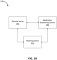
- the wasting station 110 may be part of a system 190 that includes a remote server 192 and a medication dispensing station 194.
- the wasting station 110 and the medication dispensing station 194 may be an integrated unit or more be separate stations remote from one another.
- the wasting station 110, the remote server 192, and the medication dispensing station 194 may be communicatively coupled to one another via a network.
- the network may be a wired and/or wireless network including, for example, a public land mobile network (PLMN), a local area network (LAN), a virtual local area network (VLAN), a wide area network (WAN), the Internet, a short range radio connection, for example Bluetooth, a peer-to-peer mesh network, and/or the like.
- PLMN public land mobile network
- LAN local area network
- VLAN virtual local area network
- WAN wide area network
- the Internet the Internet
- a short range radio connection for example Bluetooth, a peer-to-peer mesh network, and/or the like
- the remote server 192 may provide data and/or instructions to the wasting station 110 to implement one or more features of the wasting process consistent with implementations of the current subject matter. For example, the remote server 192 may coordinate the communication session between the wasting station 110 and a witnessing client. Additionally and/or alternatively, the remote server 192 may cause the wasting station 110 to begin, continue, and/or stop one or more wasting processes.
- FIG. 2 is a block diagram depicting aspects of the wasting station 110, consistent with implementations of the current subject matter.
- the wasting station 110 may include a controller 230 which controls one or more functions of the wasting station 110.
- the controller 230 may include, for example one or more processors, one or more computers, one or more programmable logic controllers, and/or the like.
- the controller 230 may include actuators, for example, motors, solenoids, and/or the like.
- the controller 230 may use the actuators to move mechanisms, such as a locking system 300, a manifold assembly 260, a sequencing mechanism (e.g., sequencing mechanism 266, 866), a plunger mechanism 868, a medication dispenser, and/or the like into a desired position.
- the controller 230 may include or be coupled to one or more sensors 250, for example, limit switches, flow sensors, optical sensors, tachometers, encoders, load cells, weight sensors, torque sensors, and/or the like.
- the controller 230 may use the sensors 250 to detect whether a mechanism, such as the locking system, manifold assembly, sequencing mechanism, plunger mechanism and/or medication dispenser is, for example, in position, out of position, moving, applying a force, applying a torque, and/or the like.
- the wasting station 110 may also include the user interface 130 (which may include a badge reader 238, a biometrics scanner 240, a display 236, a user input 234, and/or the like), the locking system 300 (which may include a locking mechanism 310, an enclosure 312, a smart lock 314, and/or the like), an medication analyzer 242, a camera 248, the waste container 125, a sensor 250, a manifold assembly 260, and a base 270, which are described in more detail below.
- the user interface 130 which may include a badge reader 238, a biometrics scanner 240, a display 236, a user input 234, and/or the like
- the locking system 300 which may include a locking mechanism 310, an enclosure 312, a smart lock 314, and/or the like
- an medication analyzer 242 which may include a camera 248, the waste container 125, a sensor 250, a manifold assembly 260, and a base 270, which are described in more detail below.
- the manifold assembly 260 may receive one or more medication dispensers, such as syringes.
- the manifold assembly 260 may include one, two, three, four, five, six, seven, eight, or more slots, in which at least a portion of the medication dispensers may be coupled and/or inserted.
- the manifold assembly 260 includes an interior cavity, which collects the medication dispensed from at least one of the medication dispensers.
- the interior cavity may hold at least a portion of the dispensed medication for a period of time (e.g., 1 to 10 seconds, 1 to 30 seconds, 1 to 60 seconds, 1 to 2 minutes, 1 to 10 minutes, 1 to 30 minutes, 1 to 60 minutes, 1 to 120 minutes and/or other ranges therebetween).
- the interior cavity defines a channel through which the dispensed medication passes from the medication dispenser to the waste container 125.
- the manifold assembly 260 may be positioned above the waste container 125 to allow the wasted medication to pass from the medication dispenser to the waste container 125 or the interior cavity more easily, such as via gravity, or physical manipulation of the medication dispenser (e.g., depression of a syringe, squeezing an IV bag, and/or the like).
- the manifold assembly 260 includes one or more valves to allow the medication to pass from the medication dispenser into the interior cavity, and/or from the interior cavity to the waste container 125.
- the manifold assembly 260 may include a sequencing mechanism that rotates and/or otherwise moves the manifold assembly 260 into the proper position such that the medication dispenser is appropriately located above the waste container 125. As described herein, the manifold assembly 260 may rotate and/or move so that each medication dispenser may dispense the wasted medication at the appropriate time, such as when each medication dispenser is in the proper position to waste the wasted medication.
- the waste container 125 may include a bottle, a bin, and/or the like for receiving and storing the wasted medication.
- the waste container 125 may be removably positioned on the base 270.
- the base 270 may support the waste container 125 and/or the locking system 300.
- the base 270 may include one or more sensors 250 and/or the user interface 130.
- the one or more sensors 250 may include one or more weight sensors or load cells 250A.
- the one or more weight sensors 250A may be positioned on or may be integrated with the base 270.
- the one or more weight sensors 250A may measure and/or calculate a weight of the medication wasted and deposited into the waste container 125.
- the one or more weight sensors 250A may measure a total weight of the waste container 125 and the waste deposited into the waste container 125.
- the controller 230 may remove a weight of the waste container 125 from the total weight of the waste container 125 and the waste deposited into the waste container 125 to determine the actual weight of the waste deposited into the waste container 125.
- the weight of the waste container 125 is predetermined.
- the one or more weight sensors 250A measures a weight of the waste container 125 before any waste is deposited into the waste container 125 to obtain the weight of the waste container 125.
- the controller 230 and/or the one or more weight sensors 250A measures a change in the total weight to determine the actual weight of the waste deposited into the waste container 125, such as after each medication dispenser is emptied into the waste container 125.
- the controller 230 determines a volume of the wasted medication that has been deposited into the waste container 125 based on the total weight, the actual weight of the wasted medication deposited into the waste container 125, the change in the total weight, and/or the like. As explained in more detail herein, based on the measured and/or calculated weight and/or volume of wasted medication, the wasting station 110 (e.g., via the controller 230) may determine whether a diversion of medication has occurred. For example, the controller 230 may compare the measured and/or calculated weight and/or volume of wasted medication with an expected weight and/or volume of wasted medication to verify whether the expected weight and/or volume is equal to the measured and/or calculated weight and/or volume.
- the controller 230 may determine that no diversion has occurred.
- the controller 230 may determine that a suspected diversion has occurred.
- the controller 230 may flag the waste process for further review, and/or may store, or transmit to a database, various aspects of the wasting process, such as the clinician ID, the type of medication wasted, the expected weight and/or volume of wasted medication, the measured weight and/or volume of wasted medication, and/or the like. Flagging an item for review may include storing, in a data storage device, a review indicator for the waste process. Additionally and/or alternatively, the controller 230 may trigger an alert (e.g., an audio, visual, message, or other alert) upon the detection of suspected diversion. In other implementations, however, an alert generated at the wasting station 110 may not be generated.
- an alert e.g., an audio, visual, message, or other alert
- an alert may not be generated and/or an alert may be generated at a remote location to warn a supervisor, auditor, and/or other personnel.
- the clinician 135 may not know whether the wasted medication is being flagged for audit, providing an incentive for the clinician 135 to not engage in diversion of medications.
- the wasting station 110 including the weight sensor 250A described herein more accurately measures a volume of medication that has been wasted and actually deposited into the waste container 125.
- the wasting station 110 may take into account one or more factors, such as the difference between the expected weight and/or volume of wasted medication and the measured weight and/or volume of wasted medication, the wasting user, the witnessing user, a wasting location, the substance (e.g., medication) being wasted, or other properties detectable or accessible by the wasting station 110.
- the risk of diversion may be less than when wasting a controlled substance such as oxycodone, fentanyl, and/or the like.
- a risk score may be generated based on one or more of the factors described herein, such as the difference between the expected weight and/or volume of wasted medication and the measured weight and/or volume of wasted medication, the wasting user, witnessing user, wasting location, substance being wasted, or other property detectable or accessible by the wasting station 110.
- risk score corresponds to (e.g., is greater than, less than, or equal to) a threshold
- substance being wasted may be flagged for later audit and/or an alert may be generated.
- risk scores are described in, for example, U.S. Patent Publication No. US20170109497A1 entitled “Controlled substance diversion detection systems and methods,” commonly owned and assigned, which is incorporated by reference in its entirety.
- the user interface 130 may include a badge reader 238, a biometrics scanner 240, a display 236, a user input 234, and/or the like.
- the user interface 130 may be coupled to or integrated with the wasting station 110, such as the base 270 of the wasting station 110.
- the user interface 130 forms a part of the wasting station 110, and at least a portion of the user interface 130 is coupled to an external client device, such as a computer, mobile phone, and/or the like, which is communicatively coupled to the wasting station 110.
- the user interface 130 may receive data that is used for a later audit of the wasted medication at the wasting station 110.
- the wasting station 110 may include one or more auditing features.
- the one or more auditing features may be features that allow for the wasted medication and/or the waste container 125 to be tracked and associated with a user, such as the clinician 135.
- the wasting station 110 may record information collected when the waste is deposited, including the identification tag (barcode, RFID tag, etc.) of the clinician 135 and/or the identity of the clinician 135 who deposited the waste, videos recorded during the wasting process, and physical property measurements taken during the wasting process.
- the user interface 130 may provide the badge reader 238 for reading an identification code of the clinician 135 and/or the biometrics scanner 240 for obtaining biometric features of the clinician 135.
- the identification code of the clinician 135 and/or the biometric features of the clinician may be received by the user interface 130 and be stored as a part of a record.
- the record may be linked to or associated with the clinician 135 for tracking and later auditing.
- the record may also include time and date details to associate timing with the wasting process.
- the user interface 130 includes a display 236.
- the display 236 may display one or more measured and/or calculated aspects during the wasting process. For example, the display 236 may display a weight and/or a volume of the wasted medication deposited into the waste container 125 and/or a total weight of the wasted medication and the waste container 125. In some implementations, the display 236 presents the type of medication deposited into the waste container 125.
- the user interface 130 includes a user input 234.
- the user input 234 may include dials, buttons, icons, selectable areas, or other perceivable indicia presented via the user interface 130 that, when interacted with (e.g., clicked, touched, selected, etc.), initiates an exchange of data for the wasting station 110 to present via the user interface 130.
- the user input 234 may receive information about the medication being wasted, such as an expected volume and/or weight of the medication to be wasted and deposited into the waste container 125 and/or a type of medication to be wasted and deposited into the waste container 125.
- the wasting station 110 includes one or more cameras 248.
- the camera 248 may be used to monitor and/or record the wasting process, including recording video of the user who places or otherwise connects the medication dispenser to the wasting station 110 and/or deposits the wasted medication into the wasting station 110.
- One or more cameras 248 may be used to record video of the waste item as it is placed in the waste container 125 and/or coupled to the wasting station 110.
- the one or more cameras 248 may be used for image analysis of a medication and/or medication dispenser. Image analysis of the medication and/or medication dispenser may include identification of medications based on, for example, color, size, shape, and/or markings on the medication and/or medication dispenser.
- the wasting station 110 may include a medication analyzer 242.
- the medication analyzer 242 may analyze the wasted medication.
- the medication analyzer 242 may be integrated with and/or be coupled to one or more of the sensors 250, such as a medication analysis sensor 250B, such as a flow sensor, an optical sensor, and/or a spectrometer.
- the sensor 250B and/or the medication analyzer 242 may be positioned between the manifold assembly 260 and the waste container 125 such that the wasted medication passes through and/or around the sensor 250B from the manifold assembly 260 and/or the medication dispenser to the waste container 125.
- the senor 250B is positioned along a flow path of the wasted medication from the manifold assembly 260 and/or the medication dispenser to the waste container 125, and the wasted medication contacts the sensor 250B.
- the sensor 250B may measure one or more aspects of the medication as the medication contacts and/or passes the sensor 250B.
- the sensor 250B may measure a flow rate, a volume of medication that passes the sensor 250B, a type of medication, a color for the medication, and/or the like.
- the medication analyzer 242 may be separate and/or remote from the base 270, the waste container 125, and/or the manifold assembly 260. In other implementations, the medication analyzer 242 forms a part of at least one of the base 270, the waste container 125, and/or the manifold assembly 260. As noted above, the medication analyzer 242 may perform analysis of liquid and/or solid wasted medication. For example, the medication analyzer 242 and/or the sensor 250B may perform, on a wasted medication, Raman spectroscopy, refractometry, image analysis (e.g., color, size, shape, markings, and/or the like), and/or the like to determine the type of medication being wasted.
- image analysis e.g., color, size, shape, markings, and/or the like
- the medication analyzer 242 holds at least a portion of the wasted medication as the wasted medication passes between the manifold assembly 260 and the waste container 125 to perform the analysis, such as via the sensor 250B. In other implementations, the medication analyzer 242 and/or the sensor 250B performs analysis of the wasted medication as the wasted medication passes between the manifold assembly 260 and the waste container 125.
- the medication analyzer 242 and/or the sensor 250B measures one or more aspects of the wasted medication at various times during the wasting process, such as at the beginning, middle, and end of the wasting process to confirm that the same medication is being wasted throughout the entire wasting process. This helps to prevent or reduce the likelihood of diversion as it may be more difficult for users to remove the medication being wasted and/or replace the medication with another substance during the wasting process.
- the wasting station 110 may include one or more sensors 250, such as the sensors 250A, 250B. Each of the one or more sensors 250 may be positioned at various locations on and/or in the wasting station 110, such as between the manifold assembly 260 and the waste container 125, along the flow path of the wasted medication, at the base 270, and/or the like.
- the one or more sensors 250 may measure one or more properties (e.g., physical properties) of the wasted medication and/or the waste container 125 as the wasted medication is being deposited, stored, and/or analyzed.
- the one or more sensors 250 may include one or more flow rate sensors, color sensors, density sensors, scales, load cells, weight sensors, spectrometers, optical sensors, temperature sensors, and/or other sensors.
- the wasting station 110 may include a locking system 300.
- the locking system 300 may include one or more locking features, such as a locking mechanism 310, an enclosure 312, and a smart lock 314, which help to secure the waste container and/or the wasting process.
- the locking features may help to limit or prevent diversion of the wasted medication at various stages of the wasting process by, for example, limiting access to and/or the removal of the waste container 125, the one or more sensors 250, and/or the like, to authorized personnel, such as personnel that have been verified by the wasting station 110 and/or personnel whose credentials have been received and/or stored by the wasting station 110 for later audit.
- the locking mechanism 310 includes a locking arm 311 that may be mounted on a surface of the wasting station 110.
- a locking arm 311 may be rotatably coupled to the base 270 of the wasting station 110.
- the locking arm 311 may include another end that is coupled to and/or surrounds an open end of the waste container 125 when the wasting station 110 is in a first or locked position.
- the wasting station 110 Upon receipt of credentials of an authorized user, the wasting station 110 (e.g., via the controller 230) may transmit a command to move the locking arm 311 to a second or unlocked position.
- the locking arm 311 may pivot or rotate (e.g., about a hinge) from the first position away from the waste container 125 to provide access to the waste container 125 in the second position for removal.
- the waste container 125 may be detached and/or removed from the wasting station 110.
- the manifold assembly 260 and/or one or more of the sensors 250 are coupled to and/or are supported by a portion of the locking arm 311. In such implementations, the manifold assembly 260 and/or one or more of the sensors 250 move from the first position to the second position together with the locking arm 311 when the user is authorized to remove the waste container 125.
- the locking arm 311 of the locking mechanism 310 helps to ensure that only an authorized user is provided access to the waste container 125 and/or its contents, such as during removal of the waste container 125 from the wasting station 110. This helps to limit or prevent diversion of the wasted medication.
- the locking system 300 includes the enclosure 312.
- the enclosure 312 surrounds at least a portion of the wasting station 110, such as at least the waste container 125 during the wasting process. Similar to the locking arm 311, upon receipt of credentials of an authorized user, the wasting station 110 (e.g., via the controller 230) may transmit a command to move the enclosure from a first or locked position in which the enclosure surrounds at least the waste container 125 to a second or unlocked position.
- the enclosure 312 helps to ensure that only an authorized user is provided access to the waste container 125 and/or its contents, such as during removal of the waste container 125 from the wasting station 110. This help to limit or prevent diversion of the wasted medication.
- the locking system 300 includes a smart lock 314, which may be separate from and/or integrated with one or more of the other locking features, such as the locking mechanism 310 and/or the enclosure 312.
- the smart lock 314 may be configured to release or engage based on multiple factors that are dynamically assessed. For example, the smart lock 314 may be applied to the waste container 125 of the wasting station 110.
- the smart lock 314 may include location awareness to determine a current location of the smart lock 314.
- the smart lock 314 may consider the location along with the credentials of a user when the user requests access to the locked element.
- the smart lock 314 may determine, based on the location and/or user credentials, whether to release the smart lock 314.
- the smart lock 314 may include additional and/or other sensors.
- the smart lock 314 may include a temperature sensor to record the environment around the locked element. This temperature information may affect the results of tests performed on waste items stored in the locked element.
- the smart lock 314 may include a memory element to store the sensor, location, time, and/or other information detected or generated by the smart lock 314.
- the smart lock 314 may include a communications module for transmitting sensor data along with access requests. Thus, if the clinician 135 is suspected of diverting medications, the wasting station 110 may flag for an audit the wasted medication and/or the waste container 125.
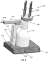
- FIGS. 3-6 illustrate an example of the wasting station 110 including the base 270 including one or more of the sensors 250 such as the weight sensor, the waste container 125, the locking system 300, the medication analyzer 242 including one or more sensors 250 such as the flow sensor and/or the optical sensor, and/or the manifold assembly 260.
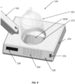
- FIG. 4 illustrates a close-up view of the base 270, consistent with implementations of the current subject matter.
- the base 270 may support the locking mechanism 310 and/or the waste container 125.
- the base 270 may include a recess 272 in which a portion of the waste container 125 is supported.
- the recess 272 helps to secure at least a portion, such as a bottom portion, of the waste container 125, to prevent or limit unauthorized removal of the waste container 125 from the wasting station 110.
- the base 270 does not include the recess 272, and instead includes a flat surface that supports the waste container 125.
- the recess 272 may include one or more sensors, such as a weight sensor (e.g., a sensor, scale, and/or load cell) 250A.
- the weight sensor 250A may be positioned on and/or may be integrated with a portion of the base 270, such as a bottom surface of the recess 272.
- the one or more weight sensors 250A may measure and/or calculate a weight of the medication wasted and deposited into the waste container 125.
- the one or more weight sensors 250A may measure a total weight of the waste container 125 and the waste deposited into the waste container 125.
- the controller 230 may remove a weight of the waste container 125 from the total weight of the waste container 125 and the waste deposited into the waste container 125 to determine the actual weight of the waste deposited into the waste container 125.
- the controller 230 and/or the one or more weight sensors 250A measures a change in the total weight to determine the actual or measured weight of the waste deposited into the waste container 125, such as after each medication dispenser is emptied into the waste container 125.
- the base 270 includes the user interface 130.
- the user interface 130 includes a display 236, which may display a weight and/or a volume of the wasted medication deposited into the waste container 125 and/or a total weight of the wasted medication and the waste container 125.
- the display 236 may additionally and/or alternatively present a volume remaining in the waste container 125.
- the controller 230 of the wasting station 110 may determine that no more medication may be wasted into the waste container 125, such as when the waste container 125 is full or has reached a predefined maximum weight and/or volume, or that no more medication may be wasted into the waste container 125 within an amount of time (e.g., 1 minute, 5 minutes, 10 minutes, 30 minutes, 1 hour, and/or the like). In such implementations, the controller 230 may determine that no more medication may be wasted into the waste container 125 based on the weight and/or volume of the medication already wasted into the waste container 125. The controller 230 may generate, via the user interface 130, one or more perceivable alerts (visual, audio, and/or the like), that indicate that the waste container 125 should be removed and no more medication should be wasted into the waste container 125.
- perceivable alerts visual, audio, and/or the like
- the user interface 130 includes a user input 234.
- the user input 234 may include dials, buttons, icons, selectable areas, or other perceivable indicia presented via the user interface 130 that, when interacted with (e.g., clicked, touched, selected, etc.), initiates an exchange of data for the wasting station 110 to present via the user interface 130.
- the user input 234 may receive information about the medication being wasted, such as an expected volume and/or weight of the medication to be wasted and deposited into the waste container 125 and/or a type of medication to be wasted and deposited into the waste container 125.
- the information about the medication being wasted may be entered by the user before the wasting process.
- the controller 230 may compare one or more measurements, such as an identified type of medication and/or a measured volume of wasted medication to the entered information about the medication, such as the type of medication and/or the expected volume of wasted medication, to determine whether a diversion has occurred, and/or a suspected diversion has occurred.
- the user interface includes an authentication feature 274, such as one or more a badge reader for reading an identification code of the clinician 135 and/or a biometrics scanner for obtaining one or more biometric features of the clinician 135.
- the authentication feature 274 may authenticate a user before, during, and/or after medication has been wasted and deposited into the wasting station 110.
- the locking mechanism 310 may move from a locked position to an unlocked position, allowing the authorized user to remove the waste container 125.
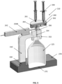
- FIG. 5 illustrates cross-sectional view of the wasting station 110, consistent with implementations of the current subject matter.
- the wasting station 110 includes a locking mechanism 310.
- the locking mechanism 310 secures the waste container 125 during the wasting process to limit or prevent diversion of the wasted medication at various stages of the wasting process by, for example, limiting access to and/or the removal of the waste container 125, the one or more sensors 250, and/or the like, to authorized personnel, such as personnel that have been authorized by the wasting station 110 and/or personnel whose credentials have been received and/or stored by the wasting station 110 for later audit.
- the locking mechanism 310 includes a locking arm 311 that may be coupled to the base 270.
- the locking mechanism 310 may include a first end 330 pivotably coupled to the base 270, and a second end 332 coupled to an open end of the waste container 125.
- the waste container 125 may include an open end that is configured to receive the wasted medication, and a closed end opposite the open end. The closed end may be positioned within the recess of the base 270.
- the second end 332 of the locking mechanism 310 may cover and/or surround at least a portion of the open end of the waste container 125 to prevent access to the contents of the waste container 125.
- the second end 332 may include a channel 334.
- the channel 334 extends through the second end 332 of the locking mechanism 310 to define at least a portion of the flow path between the medication dispenser and the waste container 125.
- the channel 334 may be in fluid communication with the manifold assembly 260 and/or the medication dispenser.
- the second end 332 of the locking mechanism 310 alone, or together with the manifold assembly 260 provides a closed system that allows the wasted medication to pass from the medication dispenser to the waste container 125 without allowing access to the wasted medication along the flowpath between the medication dispenser and the waste container 125.
- the wasting station 110 described herein securely stores the wasted medication and helps to prevent or limit diversion of the wasted medication.
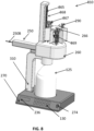
- the wasting station 110 may transmit a command to move the locking arm 311 from a first locked position (see FIGS. 3 and 5 ) to a second or unlocked position (see FIG. 6 ).
- the locking arm 311 may move (e.g., rotate, pivot, slide, and/or the like) from the first position away from the waste container 125 to provide access to the waste container 125 in the second position, for removal.
- the waste container 125 may be detached and/or removed from the wasting station 110.
- the locking mechanism 310 helps to ensure that only an authorized user is provided access to the waste container 125 and/or its contents, such as during removal of the waste container 125 from the wasting station 110. This help to limit or prevent diversion of the wasted medication.
- the locking mechanism 310 supports the manifold assembly 260 and/or the one or more sensors 250.
- the manifold assembly 260 and/or one or more of the sensors 250 may move from the first position to the second position together with the locking mechanism 310 when the user is authorized to remove the waste container 125.
- the wasting station 110 also includes the medication analyzer 242, which may analyze the wasted medication.
- the medication analyzer 242 may be integrated with and/or be coupled to one or more of the sensors 250, such as a medication analysis sensor 250B, such as a flow sensor, an optical sensor, and/or a spectrometer.
- the sensor 250B and/or the medication analyzer 242 may be positioned between the manifold assembly 260 and the waste container 125 such that the wasted medication passes through and/or around the sensor 250B from the manifold assembly 260 and/or the medication dispenser to the waste container 125.
- the senor 250B is positioned along a flow path of the wasted medication from the manifold assembly 260 and/or the medication dispenser to the waste container 125, and the wasted medication contacts the sensor 250B.
- the sensor 250B may measure one or more aspects of the medication as the medication contacts and/or passes the sensor 250B.
- the sensor 250B may measure a flow rate, a volume of medication that passes the sensor 250B, a type of medication, and/or the like.
- the medication analyzer 242 may perform an analysis of the wasted medication, to determine the type of medication being wasted. This may be useful to verify that the medication being wasted is the same as the type of medication expected to be wasted, based on, for example, the type of medication received via the user interface 130. In some implementations, the medication analyzer 242 holds at least a portion of the wasted medication to perform the analysis, such as via the sensor 250B. In other implementations, the medication analyzer 242 performs the analysis of the wasted medication as the wasted medication passes along the flow path between the manifold assembly 260 and the waste container 125.
- the medication analyzer 242 and/or the sensor 250B measures one or more aspects of the wasted medication at various times during the wasting process, such as at the beginning, middle, and end of the wasting process to confirm that the same medication is being wasted throughout the entire wasting process. This helps to prevent or reduce the likelihood of diversion as it may be more difficult for users to remove the medication being wasted and/or replace the medication with another substance during the wasting process.
- one or more medication dispensers 290 may be coupled to the wasting station 110.
- the one or more medication dispensers 290 may be coupled to the manifold assembly 260.
- the manifold assembly 260 may be cylindrical, rectangular, oval, and/or have another shape.
- the manifold assembly 260 shown in FIGS. 3-6 includes four slots 261, each configured to receive at least a portion, such as a tip end, of a corresponding medication dispenser 290.
- the slots 261 may form openings that extend through an outer surface of the manifold assembly 260.
- the manifold assembly 260 includes one, two, three, four, five, six, seven, eight, or more slots 261, each of which receive a corresponding medication dispenser 290.
- the slots 261 include a coupling feature 263 (see FIGS. 7 and 9 ) that is configured to receive at least a portion of the medication dispenser 290.
- FIG. 5 illustrates a cross-sectional view of the wasting station 110, showing an interior of the manifold assembly 260.
- the manifold assembly 260 includes an interior cavity 262.
- the interior cavity 262 may include one or more compartments 264.
- the one or more compartments 264 includes a single compartment occupying the entire interior cavity 262 that is configured to receive the medication dispensed from at least one of the medication dispensers 290.
- the one or more compartments 264 includes one, two, three, four, five, six, seven, eight, or more compartments 264, which correspond to each of the slots 261.
- each of the one or more compartments 264 may be positioned below and/or adjacent to a corresponding slot 261.
- the one or more compartments 264 of the interior cavity 262 collect the wasted medication dispensed from each corresponding medication dispenser 290.
- Each of the one or more compartments 264 may be configured to hold all or a portion of the medication dispensed from one or more of the medication dispensers 290.
- the one or more compartments 264 of the interior cavity 262 may hold at least a portion of the dispensed medication for a period of time (e.g., 1 to 10 seconds, 1 to 30 seconds, 1 to 60 seconds, 1 to 2 minutes, 1 to 10 minutes, 1 to 30 minutes, 1 to 60 minutes, 1 to 120 minutes and/or other ranges therebetween).
- the interior cavity defines a channel through which the dispensed medication passes from the medication dispenser to the waste container 125, either directly, or indirectly through a portion of the locking mechanism 310.
- the manifold assembly 260 may be positioned above the waste container 125 to allow the wasted medication to pass from the medication dispenser 290 to the waste container 125 or the interior cavity 262 more easily, such as via gravity, or by physical manipulation of the medication dispenser 290 (e.g., depression of a syringe, squeezing an IV bag, and/or the like).
- the manifold assembly 260 includes one or more valves to allow the medication to pass from the medication dispenser into the interior cavity, and/or from the interior cavity to the waste container 125.
- the one or more valves may be controlled by the controller 230.
- the controller 230 may open and/or close the one or more valves depending on which medication dispenser 290 is dispensing the medication into the waste container 125.
- At least one of the valves is coupled to a flush line.
- the flush line is configured to deliver a flushing solution to the manifold assembly 260 and/or to the flow path of the wasted medication to clean at least a portion of the flow path from the medication dispenser to the waste container 125.
- the controller 230 is configured to actuate the flush valve to allow the flushing solution to clean the flow path periodically, after a predetermined amount of medication has been wasted, after each medication dispenser 290 has been emptied, and/or at other designated time intervals.
- Flushing at least a portion of the flow path of the wasted medication helps to ensure that the flow path does not become clogged and/or that the one or more sensors are accurately measuring and/or identifying the wasted medication being deposited into the waste container 125.
- the one or more valves may allow at least some of the wasted medication to pass between the compartment 264 and the waste container 125.
- the manifold assembly 260 may include a sequencing mechanism 266.
- the sequencing mechanism 266 causes the manifold assembly 260 to rotate and/or otherwise move into a proper position such that the desired medication dispenser 290, and/or compartment 264 is appropriately located along the flow path to the waste container 125.
- the controller 230 may cause the sequencing mechanism 266 to rotate the manifold assembly 260 in a sequence.
- the sequencing mechanism 266 may rotate (e.g., automatically) the manifold assembly 260 to the next medication dispenser to dispense the wasted medication at set time intervals, after the current medication dispenser is emptied, and/or after a predetermined amount of medication has been deposited into the waste container 125.
- the sequencing mechanism 266 and/or the manifold assembly 260 allow for multiple medication dispensers 290 to be coupled to the wasting station 110, and allow for sequencing of the wasted medication to pass through the medication analyzer 242 from the manifold assembly 260 and/or the medication dispenser 290 after the medication analyzer 242 has identified the wasted medication from the corresponding medication dispenser.
- the sequencing mechanism 266 may rotate the manifold assembly 260 by 90 degrees, 180 degrees, 270 degrees, and/or the like. The sequencing mechanism helps to more efficiently and/or quickly dispense the medication into the waste container 125 with, or without, requiring a clinician to manipulate the medication dispenser.
- FIG. 7 illustrates another example of the wasting station 110, consistent with implementations of the current subject matter, in which the wasting station 110 includes an enclosure 700.
- the enclosure 700 may be formed of plastic, metal, or another material to secure at least the waste container 125, the locking mechanism 310, the sensor 250B, the manifold assembly 260, and/or the medication dispenser 290.
- the enclosure 700 is supported by the base 270 and surrounds at least a portion of the waste container 125 and the locking mechanism 310 to prevent unauthorized access to the waste container 125 and its contents, thereby reducing or eliminating the risk of diversion of the wasted medication.
- the enclosure 700 may be removably coupled to the wasting station 110, such as to the base 270.
- the controller 230 may open at least a portion of the enclosure 700 to allow access to the waste container 125.
- the controller 230 may cause the enclosure 700 to unlock, thereby allowing for the enclosure to be removed, and/or to pivot along with the locking mechanism 310 when the locking mechanism 310 moves from the unlocked position to the unlocked positon.
- the enclosure 700 may provide enhanced security for the wasting station 110, as a second means (e.g., in addition to the locking mechanism 310) of preventing unauthorized access to the waste container 125.
- the enclosure 700 is not removable until the wasting station 110 grants access to the waste container 125 via a dual-authentication process.
- the wasting station 110 may grant a first authorization to allow the locking mechanism 310 to be unlocked and a second authorization to allow the enclosure to be moved.
- the wasting station 110 may grant a first authorization to allow the enclosure to be moved and a second authorization for the locking mechanism 310 to be unlocked.
- the enclosure 700 may also shield at least a portion of the flow path between the medication dispenser 290 and the waste container 125, including the medication analyzer 242, from manipulation from an unauthorized user during the wasting process.
- FIGS. 8-11 illustrate an example of a wasting station 810, consistent with implementations of the current subject matter.
- the wasting station 810 illustrated in FIGS. 8-11 may include one or more of the same or similar properties and/or components of the wasting station 110, such as the base 270 (including one or more of the sensors 250 such as the weight sensor), the waste container 125, the locking system 300, the medication analyzer 242 including one or more sensors 250 such as the flow sensor and/or the optical sensor, and/or the manifold assembly 260.
- the wasting station 810 may additionally and/or alternatively include a sequencing mechanism 866, a plunger mechanism 868, and/or an enclosure 800.
- the wasting station 810 may allow for the medication to be wasted from the medication dispenser 290 automatically, without intervention from a user during the wasting process.
- the wasting station 810 includes the sequencing mechanism 866 and the plunger mechanism 868.
- the sequencing mechanism 866 may be the same or similar to the sequencing mechanism 266, and may include one or more of the same features and/or function as the sequencing mechanism 266.
- the sequencing mechanism 866 and the plunger mechanism 868 may be supported by and/or form a part of the manifold assembly 260.
- the sequencing mechanism 866 positions the medication dispenser 290 to the plunger mechanism 868, which causes the medication dispenser 290 (e.g., by depressing, squeezing, and/or another type of physical manipulation) to dispense the wasted medication.
- the sequencing mechanism 866 may extend from the manifold assembly 260.
- the sequencing mechanism may include structure shaped as a cylinder, rectangle, square, and/or the like.
- the sequencing mechanism 866 may include one or more attachment features 869 to secure at least one (one, two, three, four, five, six, seven, eight, or more medication dispensers) to the sequencing mechanism 866.
- the one or more attachment features 869 may include a clamp, magnet, snap-fit, or another attachment feature that secures the medication dispenser 290 to the sequencing mechanism 866.
- the one or more attachment features 869 may include one, two, three, four, five, six, seven, eight, or more attachment features 869, each of which configured to receive and secure at least a portion of a corresponding medication dispenser 290. As shown in FIG. 8 , for example, the attachment feature 869 wraps around at least a portion of the medication dispenser 290 to secure the medication dispenser to the sequencing mechanism 866. The attachment feature 269 may hold the medication dispenser 290 in an upright position to allow for the medication dispenser 290 to more easily couple to the slot 261 when the medication dispenser 290 is located by the sequencing mechanism 866 within the plunger mechanism 868.
- the sequencing mechanism 866 may include one or more walls 863 that extend radially outwardly from a central portion of the sequencing mechanism 866 (see FIGS. 10-11 ).
- the one or more walls 863 are positioned between adjacent attachment features 869.
- the one or more walls 863 are configured to separate the medication dispensers when the medication dispensers are coupled to the wasting station 810.
- the sequencing mechanism 866 rotates and/or otherwise moves into a proper position such that the desired medication dispenser 290 is appropriately within and/or coupled to the plunger mechanism 868.
- the controller 230 may cause the sequencing mechanism 866 to rotate the medication dispensers 290 in a sequence.
- the sequencing mechanism 866 may rotate (e.g., automatically), after a first medication dispenser has dispensed the wasted medication, to a second, third, or fourth medication dispenser to dispense the wasted medication at set time intervals, after the first medication dispenser is emptied, and/or after a predetermined amount of medication has been deposited into the waste container 125.
- the sequencing mechanism 866 allows for multiple medication dispensers 290 to be coupled to the wasting station 110, and allows for sequencing of the wasted medication to pass to the waste container 125 after the medication analyzer 242 has identified the wasted medication from the corresponding medication dispenser.
- the sequencing mechanism 866 may rotate in sequence by 60 degrees, 90 degrees, 120 degrees, 180 degrees, 240 degrees, 270 degrees, 300 degrees, 330 degrees, 360 degrees, and/or the like, to position the next medication dispenser.
- the sequencing mechanism 866 helps to more efficiently and/or quickly dispense the medication into the waste container 125 without requiring a clinician to manipulate the medication dispenser.
- the plunger mechanism 868 includes a dispensing feature 867 and a track 865.
- the dispensing feature 867 is configured to slide along the track 865.
- the dispensing feature 867 is configured to contact a portion of the medication dispenser 290 to cause at least some of the wasted medication to be dispensed from the medication dispenser.
- the dispensing feature 867 is configured to slide along the track 865 and contact and depress a plunger of the medication dispenser (e.g., a syringe in this scenario) to cause the wasted medication to be dispensed from the medication dispenser 290.
- the plunger mechanism 868 may include a motor or other power source, and/or may be coupled to an external power source.
- the controller 230 may activate the plunger mechanism 868 to cause the plunger mechanism 868 to contact the medication dispenser 290.
- the controller 230 may send a command to the plunger mechanism 868 to cause the plunger mechanism to dispense at least some of the wasted medication from the medication dispenser 290.
- the plunger mechanism 868 causes the medication dispenser to dispense all of the wasted medication from the medication dispenser.
- the plunger mechanism 868 (e.g., after receiving a command from the controller 230) causes the medication dispenser to dispense a first portion of the wasted medication from the medication dispenser to be analyzed by the medication analyzer 242.
- the plunger mechanism (e.g., after receiving a command from the controller 230) causes the medication dispenser to dispense the remaining portion of the wasted medication from the medication dispenser after the medication analyzer 242 has identified the wasted medication.
- the wasting station 810 may include one or more valves, such as a flush valve, that are coupled to a flush line.
- the flush line is configured to deliver a flushing solution through the slot 261 of the manifold assembly 260 and/or to the flow path of the wasted medication to clean at least a portion of the flow path from the medication dispenser to the waste container 125.
- the controller 230 is configured to actuate the flush valve to allow the flushing solution to clean the flow path periodically, after a predetermined amount of medication has been wasted, after each medication dispenser 290 has been emptied, and/or at other designated time intervals. Flushing at least a portion of the flow path of the wasted medication helps to ensure that the flow path does not become clogged and/or that the one or more sensors are accurately measuring and/or identifying the wasted medication being deposited into the waste container 125.
- FIGS. 10 and 11 illustrate an example of the enclosure 800, which may be the same or similar to the enclosure 700, and may include one or more of the same features and/or function as the enclosure 700.
- the enclosure 800 may be formed of plastic, metal, or another material.
- the enclosure 800 may be supported by the base 270, and may secure at least a portion of the wasting station 810, such as the waste container 125, the locking mechanism 310, the sensor 250B, the manifold assembly 260, the sequencing mechanism 866, the plunger mechanism 868, and/or the medication dispensers 290 coupled to the wasting station 810.
- the wasting station 810 such as the waste container 125, the locking mechanism 310, the sensor 250B, the manifold assembly 260, the sequencing mechanism 866, the plunger mechanism 868, and/or the medication dispensers 290 coupled to the wasting station 810.
- the wasting station 810 such as the waste container 125, the locking mechanism 310, the sensor 250B, the manifold assembly 260, the sequencing mechanism 866
- the enclosure 800 is supported by the base 270 and surrounds the remaining components of the wasting station 810 to prevent unauthorized access to the waste container 125 and its contents and/or the medication dispensers coupled to the wasting station 810, thereby reducing or eliminating the risk of diversion of the wasted medication during the wasting process.
- the enclosure 800 may be removably coupled to the wasting station 810, such as to the base 270.
- the controller 230 may open at least a portion of the enclosure 800 to allow access to the waste container 125, at least one medication dispenser 290, and/or the like.
- the enclosure 800 may include an access door 802.
- the controller 230 may open the access door 802 to allow access to the waste container 125, at least one medication dispenser 290, and/or the like.
- the access door 802 provides access to at least one of the medication dispensers 290 coupled to the sequencing mechanism 866 for removal of the medication dispenser 290.
- the access door 802 provides access to at least one open position on the sequencing mechanism 866 at which no medication dispenser 290 is coupled to the sequencing mechanism 866.
- the sequencing mechanism 866 may be capable of receiving a new medication dispenser at the open position.
- the access door 802 provides access to an open position on the sequencing mechanism 866 between two adjacent walls 863. Once the medication dispenser 290 is coupled to the sequencing mechanism 866, the sequencing mechanism 866 moves the medication dispenser away from the access door 802.
- the walls 863 and the access door 802, together with attachment features 869 may help to prevent or reduce the likelihood of unauthorized removal of the medication dispenser. This helps to ensure that only empty medication dispensers can be removed by an authorized user.
- the enclosure 800 may only be opened by authorized user for removal of an empty medication dispenser, loading of a medication dispenser to the wasting station 810, and/or removal of the waste container 125.
- the controller 230 may cause the enclosure 800 to unlock, thereby allowing for the enclosure to be removed, and/or to pivot along with the locking mechanism 310 when the locking mechanism 310 moves from the unlocked position to the unlocked positon.
- the enclosure 800 may provide enhanced security for the wasting station 810, as a second means (e.g., in addition to the locking mechanism 310) of preventing unauthorized access to the waste container 125.
- FIG. 12 depicts a flowchart illustrating an example process 1200, consistent with implementations of the current subject matter.
- a wasting station (e.g., the wasting station 110, 810), via a controller (e.g., the controller 230), may authenticate a user, such as the clinician 135, using the wasting station.
- the wasting station may receive one or more credentials from the user, such as via a user interface (e.g., the user interface 130).
- the user via the user interface, may be prompted to enter a user name and password, provide a fingerprint scan, provide a retina scan, swipe an employee card, or provide other information, such as biometric information, to verify the user is authorized to use the wasting station 110.
- the wasting station may perform a wasting workflow.
- the wasting station may receive, via the user interface, a type of medication to be wasted and a quantity of medication to be wasted.
- the wasting station may receive an indication, such as via the user interface, that the wasting workflow should begin.
- the wasting station may receive one or more medication dispensers.
- the user may couple one or more medication dispensers to the wasting station.
- a manifold assembly e.g., the manifold assembly 260
- a sequencing mechanism e.g., the sequencing mechanism 266, 866
- one or more slots e.g., the slots 261
- the user may position the medication dispenser such that an end of the medication that dispenses the wasted medication is coupled to a corresponding slot.
- the sequencing mechanism may receive at least a portion of the medication dispenser.
- the user may couple the medication dispenser to one or more attachment features on the sequencing mechanism.
- the wasting station includes an enclosure that surrounds at least the sequencing mechanism. After the wasting station authorizes the user, the controller of the wasting station may cause an access door in the enclosure to open, allowing access to at least one of the attachment features for the user to load the medication dispenser onto the wasting station.
- the controller causes rotation of the medication dispenser, such as via the sequencing mechanism.
- the medication dispenser is rotated by the wasting station to position the medication dispenser to dispense the wasted medication along a flow path (e.g., through the manifold assembly and/or medical analyzer) to a waste container coupled to the wasting station.
- a flow path e.g., through the manifold assembly and/or medical analyzer
- the user may physically manipulate the medication dispenser to dispense the medication.
- rotation of the medication dispenser causes the medication dispenser to couple with a plunger mechanism.
- the plunger mechanism may contact the medication dispenser to cause the wasted medication to be dispensed.
- such configurations may provide an automated process that efficiently wastes medication. This may also allow for a closed system that causes the wasted medication to be dispensed into the waste container while preventing unauthorized access to the wasted medication and/or the waste container.
- the wasting station may include one or more valves, such as a flush valve, that are coupled to a flush line.
- the flush line is configured to deliver a flushing solution through at least a portion of the flow path clean at least the portion of the flow path.
- the controller is configured to actuate the flush valve to allow the flushing solution to clean the flow path periodically, after a predetermined amount of medication has been wasted, after each medication dispenser has been emptied, and/or at other designated time intervals. Flushing at least a portion of the flow path of the wasted medication helps to ensure that the flow path does not become clogged and/or that the one or more sensors accurately measure and/or identify the wasted medication being deposited into the waste container.
- the wasting station may perform one or more wasting workflows to help limit or prevent diversion of the wasted medication.
- FIG. 13 depicts an example wasting workflow 1300, consistent with implementations of the current subject matter.
- the wasting station may receive, via the user interface, an expected volume of the wasted medication to be wasted.
- the one or more weight sensors described herein may measure a measured weight of the wasted medication deposited into the waste container.
- the base of the wasting station may include a weight sensor positioned beneath the waste container.
- the weight sensor may measure a weight of the waste container, including its contents.
- the weight sensor may determine the measured weight of the wasted medication deposited into the waste container by subtracting a weight of the waste container.
- the wasting station may determine a measured volume of the wasted medication deposited into the waste container. For example, the controller may convert the measured weight of the wasted medication to the measured volume of the wasted medication. In some implementations, the controller converts the measured weight of the wasted medication to the measured volume of the wasted medication based on a density of the wasted medication. The controller may retrieve the density of the wasted medication from a database of the wasting station and/or communicatively coupled to the wasting station. In other implementations, the wasting station receives the density of the wasted medication via the user interface.
- the wasting station (e.g., the controller) compares the measured volume of the wasted medication to the expected volume of the wasted medication. For example, the wasting station may determine whether the measured volume is the same as or within an acceptable range of the expected volume.
- the wasting station may determine whether a suspected diversion has occurred. For example, the wasting station may determine that a suspected diversion of the wasted medication has occurred based upon a determination that the measured volume is not the same as or is not within an acceptable range of the expected volume. Based on the determination of the suspected diversion, the wasting station may store information associated with the user, either collected during authorization of the user or from a database, and information associated with the wasted medication, such as the expected volume, the measured volume, and/or the like, for later audit. In some implementations, based on the determination of the suspected diversion, the wasting station generates an alert, flags the wasting workflow for later audit, generates an alert at a remote location, and/or the like.
- the wasting station may determine that a suspected diversion of the wasted medication has not occurred based upon a determination that the measured volume is the same as or is within an acceptable range of the expected volume. Based on the determination that no suspected diversion has occurred, the wasting station may store information associated with the user, either collected during authorization of the user or from a database, and information associated with the wasted medication, such as the expected volume, the measured volume, and/or the like, for later audit.
- FIG. 14 depicts another example wasting workflow 1400, consistent with implementations of the current subject matter.
- the wasting station may receive, via the user interface, an expected medication type of the wasted medication to be wasted.
- the medication analyzer (e.g., the medication analyzer 242) including one or more sensors, such as the optical sensor, described herein may identify an actual medication type of the wasted medication deposited into the waste container.
- the medication analyzer may identify the medication type of the wasted medication as the wasted medication passes along the flow path. Additionally and/or alternatively, the medication analyzer collects a portion of the wasted medication to analyze.
- the wasting station (e.g., the controller) compares the expected medication type to the actual medication type of the wasted medication. For example, the wasting station may determine whether the identified actual medication type is the same as the expected medication type.
- the wasting station may determine whether a suspected diversion has occurred. For example, the wasting station may determine that a suspected diversion of the wasted medication has occurred based upon a determination that the actual medication type is not the same as the expected medication type. Based on the determination of the suspected diversion, the wasting station may store information associated with the user, either collected during authorization of the user or from a database, and information associated with the wasted medication, such as the expected medication type, the actual medication type, and/or the like, for later audit. In some implementations, based on the determination of the suspected diversion, the wasting station generates an alert, flags the wasting workflow for later audit, generates an alert at a remote location, and/or the like.
- the wasting station may determine that a suspected diversion of the wasted medication has not occurred based upon a determination that the actual medication type is the same as the expected medication type. Based on the determination that no suspected diversion has occurred, the wasting station may store information associated with the user, either collected during authorization of the user or from a database, and information associated with the wasted medication, such as the expected medication type, the actual medication type, and/or the like, for later audit.
- the wasting station may enable access to the waste container for removal of the waste container.
- the wasting station determines that the waste container is ready for removal, such as when the waste container has reached its maximum storage capacity and/or after a medication dispenser has been emptied. Additionally and/or alternatively, the wasting station may receive a request to access and/or remove the waste container.
- the wasting station may authenticate the user.
- the wasting station may receive one or more credentials from the user, such as via the user interface, which may be associated with the wasted medication, the removal and/or access of the waste container, and/or the like, and stored for later audit.
- the user via the user interface, may be prompted to enter a user name and password, provide a fingerprint scan, provide a retina scan, swipe an employee card, or provide other information, such as biometric information, to verify the user is authorized to use the wasting station.
- the wasting station may unlock an enclosure surrounding at least a portion of the wasting station. Additionally and/or alternatively, to enable access to the waste container for removal of the waste container, the wasting station may cause a locking mechanism securing the waste container to the wasting station to unlock. Unlocking the locking mechanism may include pivoting the locking mechanism from a first position, in which a portion of the locking mechanism is positioned over an open end of the waste container, to a second positon, in which the portion of the locking mechanism is positioned away from the open end of the waste container, and allows access to the waste container.
- the wasting station may create a record of the access to the waste container. For example, as noted above, the wasting station may associate one or more of the credentials of the user with one or more details about the wasted medication. The wasting station may store the association between the user and the wasted medication and/or the waste container for later audit.
- the wasting station described herein may accurately measure and/or track the dispensed weight and/or volume of the wasted medication that is deposited into and/or captured by the waste container.
- the wasting system may additionally and/or alternatively identify the wasted medication, such as when the medication is deposited into the waste container. This helps to limit or prevent diversion of the wasted medication, by creating records of the wasting process for later audit, and by providing a system that flags a particular wasting process for later audit at least when the system determines that a suspected diversion has occurred.
- the wasting system may additionally and/or alternatively secure the wasting station, such that only authorized users may access one or more components of the wasting station, further preventing or limiting diversion of the wasted medication.
- the wasting station described herein may reduce the resources required to waste medication and allows users to perform additional tasks while the wasting station performs the wasting process. This may also improve the user experience of the wasting system while wasting medication.
- FIG. 11 depicts a block diagram illustrating a computing system 1100 consistent with implementations of the current subject matter.
- the computing system 1100 may be used to implement one or more components of the wasting system 100, such as the various components of the wasting station 110.
- the computing system 1100 may include a processor 1110, a memory 1120, a storage device 1130, and input/output device 1140.
- the processor 1110, the memory 1120, the storage device 1130, and the input/output device 1140 may be interconnected via a system bus 1150.
- the processor 1110 is capable of processing instructions for execution within the computing system 1100. Such executed instructions may implement one or more components of the wasting system 100, such as the wasting station 110.
- the processor 1110 may be a single-threaded processor.
- the processor 1110 may be a multi-threaded processor.
- the processor 1110 is capable of processing instructions stored in the memory 1120 and/or on the storage device 1130 to display graphical information for a user interface provided via the input/output device 1140.
- the memory 1120 is a computer readable medium such as volatile or nonvolatile that stores information within the computing system 1100.
- the memory 1120 may store data structures representing configuration object databases, for example.
- the storage device 1130 is capable of providing persistent storage for the computing system 1100.
- the storage device 1130 may be a floppy disk device, a hard disk device, an optical disk device, a tape device, a solid-state device, and/or any other suitable persistent storage means.
- the input/output device 1140 provides input/output operations for the computing system 1100.
- the input/output device 1140 includes a keyboard and/or pointing device.
- the input/output device 1140 includes a display unit for displaying graphical user interfaces.
- the input/output device 1140 may provide input/output operations for a network device.
- the input/output device 1140 may include Ethernet ports or other networking ports to communicate with one or more wired and/or wireless networks (e.g., a local area network (LAN), a wide area network (WAN), the Internet).
- LAN local area network
- WAN wide area network
- the Internet the Internet
- the computing system 1100 may be used to execute various interactive computer software applications that may be used for organization, analysis, and/or storage of data in various formats.
- the computing system 1100 may be used to execute any type of software applications. These applications may be used to perform various functionalities, e.g., planning functionalities (e.g., generating, managing, editing of spreadsheet documents, word processing documents, and/or any other objects, etc.), computing functionalities, communications functionalities, etc.
- the applications may include various add-in functionalities or may be standalone computing products and/or functionalities.
- the functionalities may be used to generate the user interface provided via the input/output device 1140.
- the user interface may be generated and presented to a user by the computing system 1100 (e.g., on a computer screen monitor, etc.).
- One or more aspects or features of the subject matter described herein can be realized in digital electronic circuitry, integrated circuitry, specially designed ASICs, field programmable gate arrays (FPGAs) computer hardware, firmware, software, and/or combinations thereof.
- These various aspects or features can include implementation in one or more computer programs that are executable and/or interpretable on a programmable system including at least one programmable processor, which can be special or general purpose, coupled to receive data and instructions from, and to transmit data and instructions to, a storage system, at least one input device, and at least one output device.
- the programmable system or computing system may include clients and servers. A client and server are remote from each other and typically interact through a communication network. The relationship of client and server arises by virtue of computer programs running on the respective computers and having a client-server relationship to each other.
- machine-readable medium refers to any computer program product, apparatus and/or device, such as for example magnetic discs, optical disks, memory, and Programmable Logic Devices (PLDs), used to provide machine instructions and/or data to a programmable processor, including a machine-readable medium that receives machine instructions as a machine-readable signal.
- machine-readable signal refers to any signal used to provide machine instructions and/or data to a programmable processor.
- the machine-readable medium can store such machine instructions non-transitorily, such as for example as would a non-transient solid-state memory or a magnetic hard drive or any equivalent storage medium.
- the machine-readable medium can alternatively or additionally store such machine instructions in a transient manner, such as for example, as would a processor cache or other random access memory associated with one or more physical processor cores.
- one or more aspects or features of the subject matter described herein can be implemented on a computer having a display device, such as for example a cathode ray tube (CRT) or a liquid crystal display (LCD) or a light emitting diode (LED) monitor for displaying information to the user and one or more hardware buttons, a keyboard and/or a pointing device, such as for example a mouse or a trackball, by which the user may provide input to the computer.
- a display device such as for example a cathode ray tube (CRT) or a liquid crystal display (LCD) or a light emitting diode (LED) monitor for displaying information to the user and one or more hardware buttons, a keyboard and/or a pointing device, such as for example a mouse or a trackball, by which the user may provide input to the computer.
- CTR cathode ray tube
- LCD liquid crystal display
- LED light emitting diode
- Other kinds of devices can be used to provide for interaction with
- feedback provided to the user can be any form of sensory feedback, such as for example visual feedback, auditory feedback, or tactile feedback; and input from the user may be received in any form, including acoustic, speech, or tactile input.
- Other possible input devices include touch screens or other touch-sensitive devices such as single or multi-point resistive or capacitive track pads, voice recognition hardware and software, optical scanners, optical pointers, digital image capture devices, hardware buttons, and associated interpretation software, and the like.
- spatially relative terms such as, for example, “under”, “below”, “lower”, “over”, “upper” and the like, may be used herein for ease of description to describe one element or feature's relationship to another element(s) or feature(s) as illustrated in the figures. It will be understood that the spatially relative terms are intended to encompass different orientations of the device in use or operation in addition to the orientation depicted in the figures. For example, if a device in the figures is inverted, elements described as “under” or “beneath” other elements or features would then be oriented “over” the other elements or features. Thus, the exemplary term “under” can encompass both an orientation of over and under.
- the device may be otherwise oriented (rotated 90 degrees or at other orientations) and the spatially relative descriptors used herein interpreted accordingly.
- the terms “upwardly”, “downwardly”, “vertical”, “horizontal” and the like are used herein for the purpose of explanation only unless specifically indicated otherwise.
- first and second may be used herein to describe various features/elements (including steps), these features/elements should not be limited by these terms, unless the context indicates otherwise. These terms may be used to distinguish one feature/element from another feature/element. Thus, a first feature/element discussed below could be termed a second feature/element, and similarly, a second feature/element discussed below could be termed a first feature/element without departing from the teachings provided herein.
- a numeric value may have a value that is +/- 0.1% of the stated value (or range of values), +/- 1% of the stated value (or range of values), +/- 2% of the stated value (or range of values), +/- 5% of the stated value (or range of values), +/- 10% of the stated value (or range of values), etc. Any numerical values given herein should also be understood to include about or approximately that value, unless the context indicates otherwise.
- phrases such as, for example, "at least one of' or “one or more of” may occur followed by a conjunctive list of elements or features.
- the term “and/or” may also occur in a list of two or more elements or features. Unless otherwise implicitly or explicitly contradicted by the context in which it is used, such a phrase is intended to mean any of the listed elements or features individually or any of the recited elements or features in combination with any of the other recited elements or features.
- the phrases “at least one of A and B;” “one or more of A and B;” and “A and/or B” are each intended to mean "A alone, B alone, or A and B together.”
- a similar interpretation is also intended for lists including three or more items.
- phrases “at least one of A, B, and C;” “one or more of A, B, and C;” and “A, B, and/or C” are each intended to mean “A alone, B alone, C alone, A and B together, A and C together, B and C together, or A and B and C together.”
- Use of the term “based on,” above and in the claims is intended to mean, “based at least in part on,” such that an unrecited feature or element is also permissible.
- a "user interface” (also referred to as an interactive user interface, a graphical user interface or a UI) may refer to a network based interface including data fields and/or other control elements for receiving input signals or providing electronic information and/or for providing information to the user in response to any received input signals.
- Control elements may include dials, buttons, icons, selectable areas, or other perceivable indicia presented via the UI that, when interacted with (e.g., clicked, touched, selected, etc.), initiates an exchange of data for the device presenting the UI.
- a UI may be implemented in whole or in part using technologies such as hyper-text mark-up language (HTML), FLASH TM , JAVA TM , .NET TM , C, C++, web services, or rich site summary (RSS).
- HTTP hyper-text mark-up language
- FLASH TM FLASH TM
- JAVA TM JAVA TM
- .NET TM C
- C++ web services
- RSS rich site summary
- a UI may be included in a stand-alone client (for example, thick client, fat client) configured to communicate (e.g., send or receive data) in accordance with one or more of the aspects described.
- the communication may be to or from a medical device or server in communication therewith.
- determining may include calculating, computing, processing, deriving, generating, obtaining, looking up (e.g., looking up in a table, a database or another data structure), ascertaining and the like via a hardware element without user intervention.
- determining may include receiving (e.g., receiving information), accessing (e.g., accessing data in a memory) and the like via a hardware element without user intervention.
- Determining may include resolving, selecting, choosing, establishing, and the like via a hardware element without user intervention.
- the terms “provide” or “providing” encompass a wide variety of actions.
- “providing” may include storing a value in a location of a storage device for subsequent retrieval, transmitting a value directly to the recipient via at least one wired or wireless communication medium, transmitting or storing a reference to a value, and the like.
- “Providing” may also include encoding, decoding, encrypting, decrypting, validating, verifying, and the like via a hardware element.
- a message encompasses a wide variety of formats for communicating (e.g., transmitting or receiving) information.
- a message may include a machine readable aggregation of information such as an XML document, fixed field message, comma separated message, JSON, a custom protocol, or the like.
- a message may, in some implementations, include a signal utilized to transmit one or more representations of the information. While recited in the singular, it will be understood that a message may be composed, transmitted, stored, received, etc. in multiple parts.
- a “selective” process may include determining one option from multiple options.
- a “selective” process may include one or more of: dynamically determined inputs, preconfigured inputs, or user-initiated inputs for making the determination.
- an n-input switch may be included to provide selective functionality where n is the number of inputs used to make the selection.
- correspond encompasses a structural, functional, quantitative and/or qualitative correlation or relationship between two or more objects, data sets, information and/or the like, preferably where the correspondence or relationship may be used to translate one or more of the two or more objects, data sets, information and/or the like so to appear to be the same or equal. Correspondence may be assessed using one or more of a threshold, a value range, fuzzy logic, pattern matching, a machine learning assessment model, or combinations thereof.
- data generated or detected can be forwarded to a "remote" device or location, where "remote,” means a location or device other than the location or device at which the program is executed.
- a remote location could be another location (e.g., office, lab, etc.) in the same city, another location in a different city, another location in a different state, another location in a different country, etc.
- office, lab, etc. e.g., office, lab, etc.
- the two items can be in the same room but separated, or at least in different rooms or different buildings, and can be at least one mile, ten miles, or at least one hundred miles apart.
- Communication references transmitting the data representing that information as electrical signals over a suitable communication channel (e.g., a private or public network).
- a suitable communication channel e.g., a private or public network.
- Forceing an item refers to any means of getting that item from one location to the next, whether by physically transporting that item or otherwise (where that is possible) and includes, at least in the case of data, physically transporting a medium carrying the data or communicating the data. Examples of communicating media include radio or infra-red transmission channels as well as a network connection to another computer or networked device, and the internet or including email transmissions and information recorded on websites and the like.
Landscapes
- Engineering & Computer Science (AREA)
- Business, Economics & Management (AREA)
- Health & Medical Sciences (AREA)
- General Business, Economics & Management (AREA)
- Public Health (AREA)
- General Health & Medical Sciences (AREA)
- Primary Health Care (AREA)
- Medical Informatics (AREA)
- Epidemiology (AREA)
- General Physics & Mathematics (AREA)
- Human Resources & Organizations (AREA)
- Physics & Mathematics (AREA)
- Medicinal Chemistry (AREA)
- Bioinformatics & Cheminformatics (AREA)
- Chemical & Material Sciences (AREA)
- Life Sciences & Earth Sciences (AREA)
- Theoretical Computer Science (AREA)
- Operations Research (AREA)
- Entrepreneurship & Innovation (AREA)
- Economics (AREA)
- Sustainable Development (AREA)
- Marketing (AREA)
- Strategic Management (AREA)
- Biomedical Technology (AREA)
- Quality & Reliability (AREA)
- Tourism & Hospitality (AREA)
- Accommodation For Nursing Or Treatment Tables (AREA)
- Medical Preparation Storing Or Oral Administration Devices (AREA)
- Control And Other Processes For Unpacking Of Materials (AREA)
- Animal Behavior & Ethology (AREA)
- Veterinary Medicine (AREA)
Claims (15)
- Entsorgungsstation (110), die dazu konfiguriert ist, ein verbrauchtes Medikament aus einem Medikamentenspender aufzunehmen, umfassend:eine Basis (270), die Folgendes umfasst:
einen Gewichtssensor (250A), welcher zur Messung des Gewichts eines von der Basis (270) getragenen Abfallbehälters (125) konfiguriert ist, wobei die Entsorgungsstation (110) dazu konfiguriert, auf der Grundlage des gemessenen Gewichts ein Volumen des verbrauchten Medikaments, das sich in dem Abfallbehälter (125) befindet, zu bestimmen;einen Verriegelungsmechanismus (310), der Folgendes umfasst:ein erstes Ende (330), das zum Koppeln mit der Basis (270) konfiguriert ist; undein zweites Ende (332), das zum Koppeln mit dem Abfallbehälter (125) konfiguriert ist, wenn sich der Verriegelungsmechanismus (310) in einer ersten Position befindet und von dem Abfallbehälter (125) entkoppelt ist, wenn sich der Verriegelungsmechanismus (310) von der ersten Position in eine zweite Position bewegt, wodurch die Entnahme des Abfallbehälters (125) ermöglicht wird;eine Verteileranordnung (260), welche einen inneren Hohlraum (262) aufweist, welcher dazu konfiguriert ist, mindestens einen Teil des verbrauchten Medikaments aus dem Medikamentenspender aufzunehmen, wobei mindestens der Teil des verbrauchten Medikaments dazu konfiguriert ist, aus dem inneren Hohlraum (262) in den Abfallbehälter (125) zu gelangen; undeine Medikamentenanalyseeinheit (242), welche entlang eines Flusswegs zwischen der Verteileranordnung (260) und dem Abfallbehälter (125) positioniert ist, wobei die Medikamentenanalyseeinheit (242) einen Sensor (250B) umfasst, um einen oder mehrere Aspekte des verbrauchten Medikaments zu messen. - Entsorgungsstation (110) gemäß Anspruch 1, wobei die Verteileranordnung (260) einen Sequenzierungsmechanismus (266) umfasst, wobei der Sequenzierungsmechanismus (266) dazu konfiguriert ist, die Verteileranordnung (260) zu drehen, um es einem zweiten Medikamentenspender zu ermöglichen, das verschwendete Medikament in den inneren Hohlraum (262) abzugeben.
- Entsorgungsstation (110) gemäß Anspruch 1 oder 2, wobei die Verteileranordnung (260) ein erstes Ventil, welches dazu konfiguriert ist, den Durchgang des verbrauchten Medikaments zwischen dem inneren Hohlraum (262) und dem Abfallbehälter (125) zu ermöglichen, und/oder ein zweites Ventil, welches dazu konfiguriert ist, den Durchgang des verbrauchten Medikaments zwischen dem Medikamentenspender und dem inneren Hohlraum (262) zu ermöglichen, umfasst.
- Entsorgungsstation (110) gemäß Anspruch 1, wobei der Sensor (250B) eines oder mehrere der folgenden Elemente umfasst: einen Durchflusssensor und einen optischen Sensor; wobei der Durchflusssensor dazu konfiguriert ist, das Volumen des verbrauchten Medikaments zu bestimmen; und wobei der optische Sensor dazu konfiguriert ist, einen Typ des verbrauchten Medikaments zu identifizieren.
- Entsorgungsstation (110) gemäß einem der Ansprüche 1 bis 5, wobei die Basis (270) eine Aussparung (272) umfasst, wobei die Aussparung (272) dazu konfiguriert ist, einen geschlossenen Abschnitt des Abfallbehälters (125) zu sichern, wobei der Verriegelungsmechanismus (310) dazu konfiguriert ist, einen geöffneten Abschnitt des Abfallbehälters (125) zu sichern, wobei der geöffnete Abschnitt dem geschlossenen Abschnitt gegenüberliegt, wobei der geöffnete Abschnitt dazu konfiguriert ist, das verbrauchte Medikament aufzunehmen, und wobei die Aussparung (272) bevorzugt den Gewichtssensor (250A) umfasst.
- Entsorgungsstation (110) gemäß einem der Ansprüche 1 bis 6, wobei die Basis (270) weiterhin eine Benutzerschnittstelle (130) umfasst, welche dazu konfiguriert ist, eine oder mehrere Eingaben durch einen Benutzer (135) zu empfangen, wobei die Eingabe ein erwartetes Volumen des verbrauchten Medikaments umfasst.
- Entsorgungsstation (110) gemäß einem der Ansprüche 1 bis 6, welche weiterhin ein Gehäuse (312) umfasst, welches dazu konfiguriert ist, zumindest den Abfallbehälter (125) und zumindest einen Abschnitt des Verriegelungsmechanismus (310) zu umgeben.
- Entsorgungsstation (110) gemäß einem der Ansprüche 1 bis 7, welche weiterhin einen Kolbenmechanismus (868) umfasst, der dazu konfiguriert ist, den Medikamentenspender niederdrückt, um zu bewirken, dass das verbrauchte Medikament aus dem Medikamentenspender bewegt wird.
- Entsorgungsstation (110) gemäß Anspruch 8, welche weiterhin einen Sequenzierungsmechanismus (266) umfasst, wobei der Sequenzierungsmechanismus (266) dazu konfiguriert ist, den Medikamentenspender in Kontakt mit dem Kolbenmechanismus (868) zu halten und zu positionieren, wodurch der Kolbenmechanismus (868) den Medikamentenspender herunterdrücken kann.
- Entsorgungsstation (110) gemäß Anspruch 9, wobei der Sequenzierungsmechanismus (266) dazu konfiguriert ist, den Medikamentenspender in Kontakt mit dem Kolbenmechanismus (868) zu drehen.
- Entsorgungsstation (110) gemäß einem der Ansprüche 1 bis 10, ferner umfassend eine Steuerung/Regelung (320) und mindestens einen Speicher, der Anweisungen speichert, wobei der mindestens eine Speicher Anweisungen speichert, die, wenn sie von der Steuerung (230) ausgeführt werden, zu Operationen führen, die umfassen:Authentifizieren des Benutzers (135);Durchführen eines Verbrauchsworkflows;Ermöglichen eines Zugangs zu dem Abfallbehälter (125) zur Entnahme des Abfallbehälters (125); undErstellen eines Protokolls über den Zugriff auf den Abfallbehälter (125).
- Entsorgungsstation (110) gemäß Anspruch 11, wobei das Ermöglichen des Zugangs weiterhin umfasst: Veranlassen, dass der Verriegelungsmechanismus (310) sich von der ersten Position in die zweite Position bewegt.
- Entsorgungsstation (110) gemäß einem der Ansprüche 11 bis 12, wobei das Durchführen des Verbrauchsworkflows weiterhin umfasst:Authentifizieren des Benutzers (135), wobei das Authentifizieren den Empfang einer Identifikation des Benutzers (135) umfasst;Empfangen eines erwarteten Medikationstyps des verbrauchten Medikaments;Identifizieren des tatsächlichen Medikationstyps des verschwendeten Medikaments;Vergleichen des erwarteten Medikationstyps mit dem tatsächlichen Medikationstyp;Erfassen einer vermuteten Abzweigung, wobei die Erfassung das Bestimmen umfasst, dass der tatsächliche Medikationstyp nicht mit dem erwarteten Medikationstyp übereinstimmt;Speichern der Identifikation des Benutzers (135), des erwarteten Medikationstyps und des tatsächlichen Medikationstyps.
- Entsorgungsstation (110) gemäß einem der Ansprüche 11 bis 13, wobei das Durchführen des Verbrauchsworkflows weiterhin umfasst:Authentifizieren des Benutzers (135), wobei das Authentifizierern den Empfang einer Identifikation des Benutzers (135) umfasst;Empfangen einer erwarteten Menge des verbrauchten Medikaments;Messen eines gemessenen Gewichts des in den Abfallbehälter (125) eingebrachten verbrauchten Medikaments über den Gewichtssensor (250A);Bestimmen eines gemessenen Volumens des verbrauchten Medikaments, das in den Abfallbehälter (125) eingebracht wurde, basierend auf dem gemessenen Gewicht;Vergleichen des gemessenen Volumens des verbrauchten Medikaments mit dem erwarteten Volumen des verbrauchten Medikaments;Erfassen einer vermuteten Abzweigung, wobei das Erfassen das Bestimmen umfasst, dass das gemessene Volumen nicht mit dem erwarteten Volumen übereinstimmt; undSpeichern der Identifikation des Benutzers (135), des erwarteten Volumens und des tatsächlichen Volumens.
- Entsorgungsstation (110) gemäß einem der Ansprüche 1 bis 14, wobei der Verriegelungsmechanismus (310) zumindest einen Abschnitt des Flusswegs definiert.
Applications Claiming Priority (2)
| Application Number | Priority Date | Filing Date | Title |
|---|---|---|---|
| US202063024983P | 2020-05-14 | 2020-05-14 | |
| PCT/US2021/031795 WO2021231438A1 (en) | 2020-05-14 | 2021-05-11 | Wasting station for medications |
Publications (3)
| Publication Number | Publication Date |
|---|---|
| EP4149407A1 EP4149407A1 (de) | 2023-03-22 |
| EP4149407C0 EP4149407C0 (de) | 2025-02-05 |
| EP4149407B1 true EP4149407B1 (de) | 2025-02-05 |
Family
ID=76250462
Family Applications (1)
| Application Number | Title | Priority Date | Filing Date |
|---|---|---|---|
| EP21729723.3A Active EP4149407B1 (de) | 2020-05-14 | 2021-05-11 | Abfallstation für medikamente |
Country Status (6)
| Country | Link |
|---|---|
| US (1) | US12125573B2 (de) |
| EP (1) | EP4149407B1 (de) |
| CN (1) | CN115811967A (de) |
| AU (1) | AU2021270860A1 (de) |
| CA (1) | CA3183423A1 (de) |
| WO (1) | WO2021231438A1 (de) |
Families Citing this family (2)
| Publication number | Priority date | Publication date | Assignee | Title |
|---|---|---|---|---|
| US20230077660A1 (en) * | 2021-09-10 | 2023-03-16 | Cerner Innovation, Inc. | Intelligent system for automatically testing and selecting from multiple data models for accurate diversion prediction |
| US20240203571A1 (en) * | 2022-12-16 | 2024-06-20 | Vetsnap Corp. | Systems and techniques for managing controlled substance inventory data |
Family Cites Families (158)
| Publication number | Priority date | Publication date | Assignee | Title |
|---|---|---|---|---|
| US4551133A (en) | 1984-04-16 | 1985-11-05 | American Hospital Supply Corporation | Patient controlled medication infusion system |
| US5961036A (en) | 1996-07-12 | 1999-10-05 | Diebold, Incorporated | Apparatus and method for accepting return of unused medical items |
| AU6047498A (en) | 1997-03-03 | 1998-09-22 | University Of Florida | Method and system for interactive prescription and distribution of drugs in conducting medical studies |
| US5945651A (en) | 1997-07-17 | 1999-08-31 | Chorosinski; Leonard | Remotely programmable medication dispensing system |
| US6842736B1 (en) | 1998-10-21 | 2005-01-11 | David J. Brzozowski | Drug auditing method and system |
| US8666757B2 (en) | 1999-07-28 | 2014-03-04 | Fair Isaac Corporation | Detection of upcoding and code gaming fraud and abuse in prospective payment healthcare systems |
| US9427520B2 (en) | 2005-02-11 | 2016-08-30 | Carefusion 303, Inc. | Management of pending medication orders |
| US20040172283A1 (en) | 2003-02-09 | 2004-09-02 | Vanderveen Timothy W. | Medication management and event logger and analysis system |
| US6868344B1 (en) | 2001-06-22 | 2005-03-15 | Vigilant Devices, Llc | Controlled substance analysis, wastage disposal and documentation system, apparatus and method |
| US6650964B2 (en) | 2002-04-16 | 2003-11-18 | Mckesson Automation Inc. | Medication dispensing apparatus override check and communication system |
| US7184897B2 (en) | 2002-06-19 | 2007-02-27 | Vigilant Devices, Llc | Controlled substance analysis, wastage disposal and documentation system, apparatus and method |
| US20080319795A1 (en) | 2002-11-21 | 2008-12-25 | Cdex, Inc. | System and methods for detection and identification of chemical substances |
| US20130262138A1 (en) | 2003-02-09 | 2013-10-03 | Carefusion 303, Inc. | Medication preparation queue |
| EP2284743A3 (de) | 2003-03-28 | 2013-08-14 | CareFusion 303, Inc. | Infusionsdatenkommunikationssystem |
| WO2005029286A2 (en) | 2003-09-19 | 2005-03-31 | Vesta Medical, Llc | System and method for sorting medical waste for disposal |
| US7275645B2 (en) | 2003-09-19 | 2007-10-02 | Vesta Medical, Llc | Handheld medical waste sorting device |
| US7562025B2 (en) | 2003-09-19 | 2009-07-14 | Vesta Medical, Llc | Waste sorting system with query function, and method thereof |
| US7660724B2 (en) | 2003-09-19 | 2010-02-09 | Vesta Medical, Llc | Waste sorting system utilizing removable liners |
| US7303081B2 (en) | 2003-09-19 | 2007-12-04 | Vesta Medical, Llc | Handheld medical waste sorting method |
| US7318529B2 (en) | 2003-09-19 | 2008-01-15 | Vest Medical, Llc | Method for sorting discarded and spent pharmaceutical items |
| US8195328B2 (en) | 2003-09-19 | 2012-06-05 | Vesta Medical, Llc | Combination disposal and dispensing apparatus and method |
| US7311207B2 (en) | 2003-09-19 | 2007-12-25 | Vesta Medical, Llc | System for sorting discarded and spent pharmaceutical items |
| US8340981B1 (en) | 2004-03-02 | 2012-12-25 | Cave Consulting Group, Inc. | Method, system, and computer program product for physician efficiency measurement and patient health risk stratification utilizing variable windows for episode creation |
| US20060062734A1 (en) | 2004-09-20 | 2006-03-23 | Melker Richard J | Methods and systems for preventing diversion of prescription drugs |
| AU2006212697B2 (en) | 2005-02-08 | 2007-08-09 | Sartin Group Pty Ltd | A method and apparatus for tracking the distribution of pharmaceutical products |
| US8753308B2 (en) | 2006-01-06 | 2014-06-17 | Acelrx Pharmaceuticals, Inc. | Methods for administering small volume oral transmucosal dosage forms using a dispensing device |
| US8357114B2 (en) | 2006-01-06 | 2013-01-22 | Acelrx Pharmaceuticals, Inc. | Drug dispensing device with flexible push rod |
| WO2007129319A2 (en) | 2006-05-06 | 2007-11-15 | Irody Inc | System and method for real time management of a drug regimen |
| US20080082360A1 (en) | 2006-09-29 | 2008-04-03 | Clear-View-Technologies, Inc | Inventory monitoring and control applications |
| US7693603B2 (en) | 2007-01-22 | 2010-04-06 | John David Higham | Pharmaceutical dispensing system with coordinate guidance |
| US7805391B2 (en) | 2007-02-26 | 2010-09-28 | International Business Machines Corporation | Inference of anomalous behavior of members of cohorts and associate actors related to the anomalous behavior |
| US8231578B2 (en) | 2007-02-28 | 2012-07-31 | Hospira, Inc. | System and method for sequencing channels in a multi-channel infusion pump |
| US20080306796A1 (en) | 2007-06-07 | 2008-12-11 | Cardinal Health 303, Inc. | Method and system for providing closed-loop operations consulting and optimization |
| US8280550B2 (en) | 2008-06-17 | 2012-10-02 | Omnicell, Inc. | Cabinet with remote integration |
| WO2009037615A1 (en) | 2007-09-21 | 2009-03-26 | International Business Machines Corporation | System and method for analyzing electronic data records |
| US20090160646A1 (en) | 2007-12-20 | 2009-06-25 | General Electric Company | System and method for monitoring and tracking inventories |
| JP5897798B2 (ja) | 2008-11-19 | 2016-03-30 | 株式会社根本杏林堂 | 漏出検出システム |
| US20100169063A1 (en) | 2008-12-31 | 2010-07-01 | The General Electric Company | System and Method of Modeling the Pharmacodynamic Effect to Drugs Delivered to a Patient |
| US8319669B2 (en) | 2009-04-22 | 2012-11-27 | Jeffrey C Weller | Text entry device with radial keypad layout |
| US9177269B2 (en) | 2009-05-29 | 2015-11-03 | International Business Machines Corporation | Complexity reduction of user tasks |
| JP2011022705A (ja) | 2009-07-14 | 2011-02-03 | Hitachi Ltd | 証跡管理方法、システム、及びプログラム |
| US8284068B2 (en) | 2009-07-14 | 2012-10-09 | Sam Johnson | Activity monitor to alleviate controlled substance abuse |
| US8147479B1 (en) | 2009-07-14 | 2012-04-03 | Cell Precision, LLC | Monitoring stress on a therapeutic agent during patient delivery |
| US8558659B2 (en) | 2009-07-29 | 2013-10-15 | Carefusion 303, Inc. | Urgent access medication dispensing station |
| WO2011039676A2 (en) | 2009-09-29 | 2011-04-07 | Koninklijke Philips Electronics N.V. | Assessing patient compliance |
| US20110082440A1 (en) | 2009-10-06 | 2011-04-07 | General Electric Company | Method and system for delivering analgesic drugs |
| US20120316897A1 (en) | 2011-06-10 | 2012-12-13 | AI Cure Technologies, Inc. | Method and Apparatus for Monitoring Medication Adherence |
| US20110161108A1 (en) | 2009-12-30 | 2011-06-30 | Mckesson Automation Inc. | Systems and methods for detecting diversion in drug dispensing |
| WO2011119511A1 (en) * | 2010-03-24 | 2011-09-29 | Vesta Medical, Llc | Systems and methods for disposing narcotic and other regulated waste |
| US20170017760A1 (en) | 2010-03-31 | 2017-01-19 | Fortel Analytics LLC | Healthcare claims fraud, waste and abuse detection system using non-parametric statistics and probability based scores |
| US9044377B2 (en) * | 2010-04-27 | 2015-06-02 | Cactus, Llc | Pharmaceutical waste disposal assembly |
| WO2012011997A1 (en) | 2010-04-27 | 2012-01-26 | The Travelers Companies, Inc. | System and method for detecting drug fraud and abuse |
| US8606596B1 (en) | 2010-06-27 | 2013-12-10 | Crisi Medical Systems, Inc. | Medication waste and data collection system |
| US8738177B2 (en) | 2010-07-01 | 2014-05-27 | MedAvil, Inc. | Vending machine for storage, labeling and dispensing of a container |
| AU2015264875B2 (en) | 2010-08-13 | 2017-10-12 | Respiratory Motion, Inc. | Devices and methods for respiratory variation monitoring by measurement of respiratory volumes, motion and variability |
| PH12013500457A1 (en) | 2010-09-09 | 2013-06-10 | S E A Medical Systems Inc | Systems and methods for intravenous drug management using immitance spectroscopy |
| US9636273B1 (en) | 2010-12-06 | 2017-05-02 | Vatex Explorations, LLC | Drug monitoring methods and systems |
| US9836485B2 (en) | 2011-02-25 | 2017-12-05 | International Business Machines Corporation | Auditing database access in a distributed medical computing environment |
| US9283321B2 (en) * | 2011-03-04 | 2016-03-15 | Becton, Dickinson And Company | Smart medication waste disposal |
| WO2012151332A1 (en) | 2011-05-02 | 2012-11-08 | Omnicell, Inc. | Facility-wide medication management systems |
| US10293107B2 (en) | 2011-06-22 | 2019-05-21 | Crisi Medical Systems, Inc. | Selectively Controlling fluid flow through a fluid pathway |
| US20130018356A1 (en) * | 2011-07-13 | 2013-01-17 | Crisi Medical Systems, Inc. | Characterizing medication container preparation, use, and disposal within a clinical workflow |
| US9910965B2 (en) | 2011-09-16 | 2018-03-06 | Aesynt Incorporated | Systems, methods and computer program product for monitoring interactions with a medication storage device |
| US8790307B2 (en) | 2011-12-01 | 2014-07-29 | Picolife Technologies, Llc | Drug delivery device and methods therefor |
| US10762173B2 (en) | 2011-12-05 | 2020-09-01 | Omnicell, Inc. | System and method for managing inventory at dispensing units |
| WO2013120029A1 (en) | 2012-02-10 | 2013-08-15 | Abiogenix Inc. | Dispensing device |
| GB201202368D0 (en) | 2012-02-10 | 2012-03-28 | Trakel Ltd | Tracking method |
| US9700247B2 (en) | 2012-03-21 | 2017-07-11 | Hill-Rom Services, Inc. | Patient support apparatus with redundant identity verification |
| US9443370B2 (en) | 2012-03-26 | 2016-09-13 | Omnicare, Inc. | Method and apparatus for onsite distribution of medications and medical supplies |
| US20130282392A1 (en) | 2012-04-20 | 2013-10-24 | Scott Wurm | System and method of securely storing, dispensing, and inventorying medications and samples |
| US8725532B1 (en) | 2012-06-29 | 2014-05-13 | Mckesson Financial Holdings | Systems and methods for monitoring controlled substance distribution |
| US11116892B2 (en) | 2012-08-28 | 2021-09-14 | Osprey Medical, Inc. | Medium injection diversion and measurement |
| US20140081652A1 (en) | 2012-09-14 | 2014-03-20 | Risk Management Solutions Llc | Automated Healthcare Risk Management System Utilizing Real-time Predictive Models, Risk Adjusted Provider Cost Index, Edit Analytics, Strategy Management, Managed Learning Environment, Contact Management, Forensic GUI, Case Management And Reporting System For Preventing And Detecting Healthcare Fraud, Abuse, Waste And Errors |
| US11246800B2 (en) * | 2012-10-05 | 2022-02-15 | Alixa Rx, Llc | Locking canister for dispensing medications |
| US20140149131A1 (en) | 2012-11-27 | 2014-05-29 | Covectra, Inc. | Methods and systems for drug diversion tracking |
| US9342484B2 (en) | 2013-01-30 | 2016-05-17 | Carefusion 303, Inc. | Variable dose dispensing system |
| US20170083681A1 (en) | 2013-02-16 | 2017-03-23 | Michael Phillip Sprintz | Method and apparatus for generating a clinical presentation related to controlled substance abuse or diversion |
| WO2014127234A1 (en) | 2013-02-16 | 2014-08-21 | Diversion Detection Technologies, Llc | Method and apparatus for detecting controlled substance abuse or diversion |
| US9355071B2 (en) | 2013-03-01 | 2016-05-31 | Sas Institute Inc. | System and method for Multivariate outlier detection |
| US9354178B2 (en) | 2013-03-05 | 2016-05-31 | Smiths Detection Inc. | Transmission raman sample analysis |
| US20140276560A1 (en) | 2013-03-13 | 2014-09-18 | Carefusion 303, Inc. | Infusion Management Platform For Medication Container Volume Tracking |
| WO2014145074A1 (en) | 2013-03-15 | 2014-09-18 | Makefield Llc | Functional desiccants |
| US9523635B2 (en) | 2013-06-20 | 2016-12-20 | Rigaku Raman Technologies, Inc. | Apparatus and methods of spectral searching using wavelet transform coefficients |
| US9202052B1 (en) | 2013-06-21 | 2015-12-01 | Emc Corporation | Dynamic graph anomaly detection framework and scalable system architecture |
| US20160166766A1 (en) | 2013-07-12 | 2016-06-16 | Oscillari Llc | Acoustic based drug delivery monitor |
| US9561324B2 (en) | 2013-07-19 | 2017-02-07 | Bigfoot Biomedical, Inc. | Infusion pump system and method |
| US20150061832A1 (en) | 2013-09-05 | 2015-03-05 | University Of Utah Research Foundation | Directly observed thearpy using mobile technology |
| TW201517616A (zh) | 2013-10-18 | 2015-05-01 | Amaryllo International Inc | 監視攝影裝置之控制方法及控制系統 |
| US9171280B2 (en) | 2013-12-08 | 2015-10-27 | Kit Check, Inc. | Medication tracking |
| US9576355B2 (en) | 2014-01-31 | 2017-02-21 | Catamaran Corporation | System and method of monitoring and confirming medication dosage |
| US9779407B2 (en) | 2014-08-08 | 2017-10-03 | Brighterion, Inc. | Healthcare fraud preemption |
| GB201405561D0 (en) | 2014-03-27 | 2014-05-14 | Smiths Detection Watford Ltd | Detector inlet and sampling method |
| US20210005324A1 (en) | 2018-08-08 | 2021-01-07 | Hc1.Com Inc. | Methods and systems for a health monitoring command center and workforce advisor |
| US9572748B2 (en) * | 2014-03-28 | 2017-02-21 | Celico Partnership | Prescription container and service for monitoring patients |
| US20150286783A1 (en) | 2014-04-02 | 2015-10-08 | Palo Alto Research Center Incorporated | Peer group discovery for anomaly detection |
| US20150294079A1 (en) | 2014-04-11 | 2015-10-15 | Pierre R. Bergougnan | Telehealth system and process |
| US20150362350A1 (en) | 2014-05-09 | 2015-12-17 | Marqmetrix, Inc. | External Sensing Device for Machine Fluid Status and Machine Operation Status |
| CA2948490A1 (en) | 2014-05-09 | 2015-11-12 | Marqmetrix, Inc. | Constant fluid level and equipment monitor |
| WO2015187682A1 (en) | 2014-06-02 | 2015-12-10 | Marqmetrix, Inc. | External sensing device for machine fluid status and machine operation status |
| US10473585B2 (en) | 2014-06-16 | 2019-11-12 | Murphy Brown, Llc | Method and system for measuring a physical parameter of a particulate material |
| US10489555B2 (en) * | 2014-07-21 | 2019-11-26 | Qualanex, Llc | Medication processing kiosk |
| US10101269B2 (en) | 2014-07-30 | 2018-10-16 | Smiths Detection Inc. | Estimation of water interference for spectral correction |
| US9752935B2 (en) | 2014-08-29 | 2017-09-05 | Marqmetrix, Inc. | Portable analytical equipment |
| WO2016036657A1 (en) | 2014-09-03 | 2016-03-10 | Zebra Skimmers Corp. | Liquid supply systems |
| US20160161705A1 (en) | 2014-12-04 | 2016-06-09 | Marqmetrix, Inc. | Removable optical assembly |
| US20160259911A1 (en) | 2015-03-03 | 2016-09-08 | Danny P. Koester | Automated Medication Adherence System |
| US20160259904A1 (en) | 2015-03-03 | 2016-09-08 | Abide Technologies, Llc | System and method for providing dispensing security for controlled substances within a care facility |
| US20160283691A1 (en) | 2015-03-23 | 2016-09-29 | Ammar Ali | System, Method and Container Assembly for Prevention of Drug Diversion and for Compliance Assurance |
| US10591388B2 (en) | 2015-04-27 | 2020-03-17 | Virtual Fluid Monitoring Services LLC | Fluid analysis and monitoring using optical spectroscopy |
| US20170032102A1 (en) | 2015-05-01 | 2017-02-02 | Ahkeo Ventures LLC | Systems and methods for medical dispensing, management and monitoring |
| AU2016257732B2 (en) | 2015-05-04 | 2021-07-01 | Carefusion 303, Inc. | Fluid infusion systems and methods |
| US9796526B2 (en) | 2015-07-27 | 2017-10-24 | Call2Recycle, Inc. | Receptacle for secure collection of waste |
| US20170076065A1 (en) | 2015-09-10 | 2017-03-16 | Lynx Rx, Inc. | System, device, and automated method for verification of medication integrity and chain of custody |
| US9953160B2 (en) | 2015-10-13 | 2018-04-24 | Paypal, Inc. | Applying multi-level clustering at scale to unlabeled data for anomaly detection and security |
| US10515722B2 (en) | 2015-10-15 | 2019-12-24 | Omnicell, Inc. | Medical equipment with diversion mechanism |
| US10915604B2 (en) | 2015-10-16 | 2021-02-09 | Carefusion 303, Inc. | Controlled substance diversion detection systems and methods |
| US20180247703A1 (en) | 2015-11-13 | 2018-08-30 | Mayo Foundation For Medical Education And Research | Medication administration auditing systems and methods |
| US10032344B2 (en) | 2016-03-29 | 2018-07-24 | Vigilant Waste Technologies, Inc. | Systems, apparatuses, and methods for disposing and documenting the disposal of controlled substances |
| US10675221B2 (en) | 2016-07-26 | 2020-06-09 | The Regents Of The University Of California | Systems and methods for controlling and monitoring medication dispensation |
| US20180039736A1 (en) | 2016-08-08 | 2018-02-08 | Alicia Williams | System and Method for Automated Tracking and Analysis of Pharmaceutical Use within Healthcare Facilities |
| US11752274B2 (en) | 2016-08-17 | 2023-09-12 | Sawhney Nisha | Injection monitoring device and system |
| US10345242B2 (en) | 2016-11-08 | 2019-07-09 | B&W Tek Llc | Reverse intensity correction for Raman spectral library search |
| US10956538B2 (en) | 2016-12-03 | 2021-03-23 | Verily Life Sciences Llc | Low-power systems and methods for determining measurement times of values obtained by a measuring device |
| US20180165417A1 (en) | 2016-12-14 | 2018-06-14 | David R. Hall | Bathroom Telemedicine Station |
| US10631777B2 (en) | 2017-01-11 | 2020-04-28 | Boston Scientific Neuromodulation Corporation | Pain management based on functional measurements |
| US11670422B2 (en) | 2017-01-13 | 2023-06-06 | Microsoft Technology Licensing, Llc | Machine-learning models for predicting decompensation risk |
| US9958324B1 (en) | 2017-02-15 | 2018-05-01 | MarqMetrix Inc. | Enclosed benchtop raman spectrometry device |
| US10408675B2 (en) | 2017-02-15 | 2019-09-10 | Marqmetrix, Inc. | Enclosed benchtop Raman spectrometry device |
| WO2018160756A1 (en) | 2017-02-28 | 2018-09-07 | Marqmetrix Inc | Fluid flow cell including a spherical lens |
| US10187288B2 (en) | 2017-03-09 | 2019-01-22 | Caterpillar Inc. | Communicating data link information using a light source |
| CA3062858A1 (en) | 2017-05-12 | 2018-11-15 | The Regents Of The University Of Michigan | Individual and cohort pharmacological phenotype prediction platform |
| US10522252B2 (en) | 2017-06-16 | 2019-12-31 | Carefusion 303, Inc. | Opioid management system |
| US20180365385A1 (en) | 2017-06-16 | 2018-12-20 | University Hospitals Of Cleveland | Monitoring and evaluating patient reactions to medications |
| US20190139638A1 (en) | 2017-06-19 | 2019-05-09 | Codonics, Inc. | Method and apparatus for labeling and tracking medicinal substances |
| US10318729B2 (en) | 2017-07-26 | 2019-06-11 | Forcepoint, LLC | Privacy protection during insider threat monitoring |
| WO2019028004A1 (en) | 2017-07-31 | 2019-02-07 | Smiths Detection Inc. | SYSTEM FOR DETERMINING THE PRESENCE OF A SUBSTANCE OF INTEREST IN A SAMPLE |
| US11448588B2 (en) | 2017-08-07 | 2022-09-20 | Horiba, Ltd. | Analyzer, analysis method, analyzer program, and analysis learning device |
| JP6981817B2 (ja) | 2017-08-31 | 2021-12-17 | 株式会社堀場製作所 | 分光分析装置及び分光分析方法 |
| US20190088354A1 (en) | 2017-09-01 | 2019-03-21 | Kit Check, Inc. | Identifying discrepancies between events from disparate systems |
| US11170484B2 (en) | 2017-09-19 | 2021-11-09 | Aic Innovations Group, Inc. | Recognition of suspicious activities in medication administration |
| US20190117883A1 (en) | 2017-10-23 | 2019-04-25 | Cerebral Therapetuics LLC | Syringe for delivering medications to implanted drug delivery systems and methods for use thereof |
| US11424020B2 (en) | 2017-12-08 | 2022-08-23 | Actual Healthcare Solutions | Cloud-based interactive digital medical imaging and patient health information exchange platform |
| US11081220B2 (en) | 2018-02-02 | 2021-08-03 | Carefusion 303, Inc. | System and method for dispensing medication |
| WO2019170685A1 (en) | 2018-03-06 | 2019-09-12 | Blisterpartner B.V. | System and method for medication preparation and verification |
| CA3099146A1 (en) | 2018-05-04 | 2019-11-07 | Carefusion 303, Inc. | Peer community based anomalous behavior detection |
| US20190355461A1 (en) | 2018-05-21 | 2019-11-21 | Henry Ford Health System | Prescription medication diversion analysis and reporting |
| US11135131B2 (en) * | 2018-09-14 | 2021-10-05 | Board Of Trustees Of Michigan State University | Medication bottle with anti-tampering features |
| SE542892C2 (en) | 2018-12-06 | 2020-08-18 | Eleiko Group Ab | Open barbell with stand |
| US12064797B2 (en) * | 2018-12-27 | 2024-08-20 | Stryker Corporation | Method of disposing of waste receiver, waste receiver for pharmaceutical waste and method of assembling the waste receiver |
| DE112020000335T5 (de) | 2019-01-07 | 2021-10-21 | Carefusion 303, Inc. | Auf maschinellem lernen basierende sicherheitssteuerung |
| US11984212B2 (en) | 2019-01-10 | 2024-05-14 | Carefusion 303, Inc. | System for monitoring dose pattern and patient response |
| US10980940B2 (en) | 2019-01-18 | 2021-04-20 | Carefusion 303, Inc. | Medication tracking system |
| US20200312442A1 (en) * | 2019-04-01 | 2020-10-01 | Abbey Garrett LLC | Waste management apparatus, system, and method |
| EP3948759A4 (de) | 2019-04-05 | 2022-12-21 | Midas Healthcare Solutions, Inc. | Systeme und verfahren zur medikamentenverwaltung |
| US11481739B1 (en) * | 2019-04-17 | 2022-10-25 | Deberenia McKinzie | Medication disposal, treatment and reconciliation kiosk device |
| US11037666B1 (en) | 2019-05-29 | 2021-06-15 | Bottomline Technologies, Inc. | Method and apparatus for detecting diverted drugs |
| MX2022000842A (es) | 2019-07-24 | 2022-03-17 | Carefusion 303 Inc | Estacion de desecho inteligente para medicamentos. |
| CN115380333A (zh) | 2020-02-11 | 2022-11-22 | 康尔福盛303公司 | 转移检测系统 |
-
2021
- 2021-05-11 WO PCT/US2021/031795 patent/WO2021231438A1/en not_active Ceased
- 2021-05-11 AU AU2021270860A patent/AU2021270860A1/en active Pending
- 2021-05-11 CN CN202180047982.8A patent/CN115811967A/zh active Pending
- 2021-05-11 EP EP21729723.3A patent/EP4149407B1/de active Active
- 2021-05-11 CA CA3183423A patent/CA3183423A1/en active Pending
- 2021-05-11 US US17/317,507 patent/US12125573B2/en active Active
Also Published As
| Publication number | Publication date |
|---|---|
| EP4149407A1 (de) | 2023-03-22 |
| EP4149407C0 (de) | 2025-02-05 |
| CA3183423A1 (en) | 2021-11-18 |
| WO2021231438A1 (en) | 2021-11-18 |
| AU2021270860A1 (en) | 2022-12-08 |
| US12125573B2 (en) | 2024-10-22 |
| CN115811967A (zh) | 2023-03-17 |
| US20210358257A1 (en) | 2021-11-18 |
Similar Documents
| Publication | Publication Date | Title |
|---|---|---|
| US20250226075A1 (en) | Modular witnessing device | |
| US20210027259A1 (en) | Smart wasting station for medications | |
| US12249421B2 (en) | Opioid management system | |
| US20220254470A1 (en) | Systems and methods for medication management | |
| JP7725483B2 (ja) | 流用検知システム | |
| EP4149407B1 (de) | Abfallstation für medikamente | |
| EP4664480A2 (de) | Umleitungserkennungssystem |
Legal Events
| Date | Code | Title | Description |
|---|---|---|---|
| STAA | Information on the status of an ep patent application or granted ep patent |
Free format text: STATUS: UNKNOWN |
|
| STAA | Information on the status of an ep patent application or granted ep patent |
Free format text: STATUS: THE INTERNATIONAL PUBLICATION HAS BEEN MADE |
|
| PUAI | Public reference made under article 153(3) epc to a published international application that has entered the european phase |
Free format text: ORIGINAL CODE: 0009012 |
|
| STAA | Information on the status of an ep patent application or granted ep patent |
Free format text: STATUS: REQUEST FOR EXAMINATION WAS MADE |
|
| 17P | Request for examination filed |
Effective date: 20221130 |
|
| AK | Designated contracting states |
Kind code of ref document: A1 Designated state(s): AL AT BE BG CH CY CZ DE DK EE ES FI FR GB GR HR HU IE IS IT LI LT LU LV MC MK MT NL NO PL PT RO RS SE SI SK SM TR |
|
| DAV | Request for validation of the european patent (deleted) | ||
| DAX | Request for extension of the european patent (deleted) | ||
| GRAP | Despatch of communication of intention to grant a patent |
Free format text: ORIGINAL CODE: EPIDOSNIGR1 |
|
| STAA | Information on the status of an ep patent application or granted ep patent |
Free format text: STATUS: GRANT OF PATENT IS INTENDED |
|
| INTG | Intention to grant announced |
Effective date: 20240906 |
|
| GRAS | Grant fee paid |
Free format text: ORIGINAL CODE: EPIDOSNIGR3 |
|
| GRAA | (expected) grant |
Free format text: ORIGINAL CODE: 0009210 |
|
| STAA | Information on the status of an ep patent application or granted ep patent |
Free format text: STATUS: THE PATENT HAS BEEN GRANTED |
|
| AK | Designated contracting states |
Kind code of ref document: B1 Designated state(s): AL AT BE BG CH CY CZ DE DK EE ES FI FR GB GR HR HU IE IS IT LI LT LU LV MC MK MT NL NO PL PT RO RS SE SI SK SM TR |
|
| REG | Reference to a national code |
Ref country code: GB Ref legal event code: FG4D |
|
| REG | Reference to a national code |
Ref country code: CH Ref legal event code: EP |
|
| REG | Reference to a national code |
Ref country code: IE Ref legal event code: FG4D |
|
| REG | Reference to a national code |
Ref country code: DE Ref legal event code: R096 Ref document number: 602021025767 Country of ref document: DE |
|
| U01 | Request for unitary effect filed |
Effective date: 20250226 |
|
| U07 | Unitary effect registered |
Designated state(s): AT BE BG DE DK EE FI FR IT LT LU LV MT NL PT RO SE SI Effective date: 20250304 |
|
| U20 | Renewal fee for the european patent with unitary effect paid |
Year of fee payment: 5 Effective date: 20250423 |
|
| PG25 | Lapsed in a contracting state [announced via postgrant information from national office to epo] |
Ref country code: RS Free format text: LAPSE BECAUSE OF FAILURE TO SUBMIT A TRANSLATION OF THE DESCRIPTION OR TO PAY THE FEE WITHIN THE PRESCRIBED TIME-LIMIT Effective date: 20250505 |
|
| PG25 | Lapsed in a contracting state [announced via postgrant information from national office to epo] |
Ref country code: PL Free format text: LAPSE BECAUSE OF FAILURE TO SUBMIT A TRANSLATION OF THE DESCRIPTION OR TO PAY THE FEE WITHIN THE PRESCRIBED TIME-LIMIT Effective date: 20250205 |
|
| PG25 | Lapsed in a contracting state [announced via postgrant information from national office to epo] |
Ref country code: ES Free format text: LAPSE BECAUSE OF FAILURE TO SUBMIT A TRANSLATION OF THE DESCRIPTION OR TO PAY THE FEE WITHIN THE PRESCRIBED TIME-LIMIT Effective date: 20250205 |
|
| PGFP | Annual fee paid to national office [announced via postgrant information from national office to epo] |
Ref country code: GB Payment date: 20250423 Year of fee payment: 5 |
|
| PG25 | Lapsed in a contracting state [announced via postgrant information from national office to epo] |
Ref country code: NO Free format text: LAPSE BECAUSE OF FAILURE TO SUBMIT A TRANSLATION OF THE DESCRIPTION OR TO PAY THE FEE WITHIN THE PRESCRIBED TIME-LIMIT Effective date: 20250505 Ref country code: IS Free format text: LAPSE BECAUSE OF FAILURE TO SUBMIT A TRANSLATION OF THE DESCRIPTION OR TO PAY THE FEE WITHIN THE PRESCRIBED TIME-LIMIT Effective date: 20250605 |
|
| PG25 | Lapsed in a contracting state [announced via postgrant information from national office to epo] |
Ref country code: HR Free format text: LAPSE BECAUSE OF FAILURE TO SUBMIT A TRANSLATION OF THE DESCRIPTION OR TO PAY THE FEE WITHIN THE PRESCRIBED TIME-LIMIT Effective date: 20250205 |
|
| PG25 | Lapsed in a contracting state [announced via postgrant information from national office to epo] |
Ref country code: GR Free format text: LAPSE BECAUSE OF FAILURE TO SUBMIT A TRANSLATION OF THE DESCRIPTION OR TO PAY THE FEE WITHIN THE PRESCRIBED TIME-LIMIT Effective date: 20250506 |
|
| PG25 | Lapsed in a contracting state [announced via postgrant information from national office to epo] |
Ref country code: SM Free format text: LAPSE BECAUSE OF FAILURE TO SUBMIT A TRANSLATION OF THE DESCRIPTION OR TO PAY THE FEE WITHIN THE PRESCRIBED TIME-LIMIT Effective date: 20250205 |
|
| PG25 | Lapsed in a contracting state [announced via postgrant information from national office to epo] |
Ref country code: CZ Free format text: LAPSE BECAUSE OF FAILURE TO SUBMIT A TRANSLATION OF THE DESCRIPTION OR TO PAY THE FEE WITHIN THE PRESCRIBED TIME-LIMIT Effective date: 20250205 |
|
| PG25 | Lapsed in a contracting state [announced via postgrant information from national office to epo] |
Ref country code: SK Free format text: LAPSE BECAUSE OF FAILURE TO SUBMIT A TRANSLATION OF THE DESCRIPTION OR TO PAY THE FEE WITHIN THE PRESCRIBED TIME-LIMIT Effective date: 20250205 |