EP4149151B1 - Verfahren und vorrichtung zur verwendung in einem knoten einer drahtlosen kommunikation - Google Patents
Verfahren und vorrichtung zur verwendung in einem knoten einer drahtlosen kommunikation Download PDFInfo
- Publication number
- EP4149151B1 EP4149151B1 EP21847310.6A EP21847310A EP4149151B1 EP 4149151 B1 EP4149151 B1 EP 4149151B1 EP 21847310 A EP21847310 A EP 21847310A EP 4149151 B1 EP4149151 B1 EP 4149151B1
- Authority
- EP
- European Patent Office
- Prior art keywords
- type monitoring
- relevant parameter
- monitoring
- signal
- time
- Prior art date
- Legal status (The legal status is an assumption and is not a legal conclusion. Google has not performed a legal analysis and makes no representation as to the accuracy of the status listed.)
- Active
Links
Images


Classifications
-
- H—ELECTRICITY
- H04—ELECTRIC COMMUNICATION TECHNIQUE
- H04W—WIRELESS COMMUNICATION NETWORKS
- H04W72/00—Local resource management
- H04W72/04—Wireless resource allocation
- H04W72/044—Wireless resource allocation based on the type of the allocated resource
- H04W72/0453—Resources in frequency domain, e.g. a carrier in FDMA
-
- H—ELECTRICITY
- H04—ELECTRIC COMMUNICATION TECHNIQUE
- H04W—WIRELESS COMMUNICATION NETWORKS
- H04W74/00—Wireless channel access
- H04W74/08—Non-scheduled access, e.g. ALOHA
- H04W74/0808—Non-scheduled access, e.g. ALOHA using carrier sensing, e.g. carrier sense multiple access [CSMA]
-
- H—ELECTRICITY
- H04—ELECTRIC COMMUNICATION TECHNIQUE
- H04W—WIRELESS COMMUNICATION NETWORKS
- H04W72/00—Local resource management
- H04W72/04—Wireless resource allocation
- H04W72/044—Wireless resource allocation based on the type of the allocated resource
-
- H—ELECTRICITY
- H04—ELECTRIC COMMUNICATION TECHNIQUE
- H04L—TRANSMISSION OF DIGITAL INFORMATION, e.g. TELEGRAPHIC COMMUNICATION
- H04L5/00—Arrangements affording multiple use of the transmission path
- H04L5/0001—Arrangements for dividing the transmission path
- H04L5/0014—Three-dimensional division
- H04L5/0023—Time-frequency-space
-
- H—ELECTRICITY
- H04—ELECTRIC COMMUNICATION TECHNIQUE
- H04L—TRANSMISSION OF DIGITAL INFORMATION, e.g. TELEGRAPHIC COMMUNICATION
- H04L5/00—Arrangements affording multiple use of the transmission path
- H04L5/003—Arrangements for allocating sub-channels of the transmission path
- H04L5/0053—Allocation of signalling, i.e. of overhead other than pilot signals
-
- H—ELECTRICITY
- H04—ELECTRIC COMMUNICATION TECHNIQUE
- H04L—TRANSMISSION OF DIGITAL INFORMATION, e.g. TELEGRAPHIC COMMUNICATION
- H04L5/00—Arrangements affording multiple use of the transmission path
- H04L5/0091—Signalling for the administration of the divided path, e.g. signalling of configuration information
-
- H—ELECTRICITY
- H04—ELECTRIC COMMUNICATION TECHNIQUE
- H04W—WIRELESS COMMUNICATION NETWORKS
- H04W24/00—Supervisory, monitoring or testing arrangements
- H04W24/02—Arrangements for optimising operational condition
-
- H—ELECTRICITY
- H04—ELECTRIC COMMUNICATION TECHNIQUE
- H04W—WIRELESS COMMUNICATION NETWORKS
- H04W72/00—Local resource management
- H04W72/04—Wireless resource allocation
- H04W72/044—Wireless resource allocation based on the type of the allocated resource
- H04W72/0446—Resources in time domain, e.g. slots or frames
-
- H—ELECTRICITY
- H04—ELECTRIC COMMUNICATION TECHNIQUE
- H04L—TRANSMISSION OF DIGITAL INFORMATION, e.g. TELEGRAPHIC COMMUNICATION
- H04L5/00—Arrangements affording multiple use of the transmission path
- H04L5/003—Arrangements for allocating sub-channels of the transmission path
- H04L5/0032—Distributed allocation, i.e. involving a plurality of allocating devices, each making partial allocation
- H04L5/0033—Distributed allocation, i.e. involving a plurality of allocating devices, each making partial allocation each allocating device acting autonomously, i.e. without negotiation with other allocating devices
-
- H—ELECTRICITY
- H04—ELECTRIC COMMUNICATION TECHNIQUE
- H04L—TRANSMISSION OF DIGITAL INFORMATION, e.g. TELEGRAPHIC COMMUNICATION
- H04L5/00—Arrangements affording multiple use of the transmission path
- H04L5/003—Arrangements for allocating sub-channels of the transmission path
- H04L5/0048—Allocation of pilot signals, i.e. of signals known to the receiver
Definitions
- the present application relates to a transmission method and apparatus in a wireless communications system, and in particular, to a transmission solution and apparatus related to an unlicensed spectrum in wireless communication.
- a key technology of NR is to support beam-based signal transmission.
- a main application scenario of the technology is to enhance coverage of NR devices operating in a millimeter-wave frequency band (for example, a frequency band above 6 GHz).
- a beam-based transmission technology is also needed in a low frequency band (for example, a frequency band below 6 GHz) to support massive antennas.
- a radio frequency signal forms a relatively strong beam in a specific spatial direction, but the signal is relatively weak in other directions.
- a beam of a transmitting set and a beam of a receiving set may be accurately aligned with each other, so that a signal is sent and received with relatively strong power, thereby improving coverage performance.
- Beam measurement and feedback of an NR system operating in a millimeter-wave frequency band may be implemented by using a plurality of synchronization broadcast signal blocks (SS/PBCH block, (SSB)) and a plurality of channel state information-reference signals (CSI-RS). Different SSBs or CSI-RSs may be transmitted by using different beams.
- SSB synchronization broadcast signal blocks
- CSI-RS channel state information-reference signals
- Different SSBs or CSI-RSs may be transmitted by using different beams.
- UE implements beam alignment by measuring an SSB or a CSI-RS sent by a next generation Node B (gNB) and feeding back an SSB index or a CSI-RS resource number.
- gNB next generation Node B
- 3GPP Release 17 considers extending application of NR to an unlicensed spectrum above 52.6 GHz.
- LBT Listen Before Talk
- a Listen Before Talk (LBT) technology is used to avoid interference caused when a plurality of transmitting sets occupy a same frequency resource.
- beam-based signal transmission is obviously directional, and thus a directional LBT technology is more suitable to be used to avoid interference.
- a transmitting set (a base station or user equipment) first performs energy detection in a defer duration. If a result of the detection indicates that a channel is idle, backoff needs to be performed, and energy detection is performed during the backoff. Time of the backoff is counted by using a clear channel assessment (CCA) slot duration as a unit. A quantity of slot durations of the backoff is obtained by the transmitting set via random selection in a contention window size (CWS). Therefore, a duration period of Cat 4 LBT is uncertain.
- Category 2 LBT (Cat 2 LBT, referring to 3GPP TR36.889) is another type of LBT.
- Cat 2 LBT determines whether a channel is idle by evaluating strength of energy in a specific period of time. A duration period of Cat 2 LBT is certain.
- NR uses a similar mechanism.
- Cat 4 LBT is also referred to as a Type 1 downlink channel access procedure.
- Cat 4 LBT is also referred to as a Type 1 uplink channel access procedure.
- Cat 2 LBT is also referred to as a Type 2 downlink channel access procedure.
- Cat 2 LBT is also referred to as a Type 2 uplink channel access procedure.
- a Type 2 uplink channel access procedure For specific definitions, reference may be made to 3GPP TS37.213.
- Cat 4 LBT in the present application is also used to represent a Type 1 downlink channel access procedure or a Type 1 uplink channel access procedure.
- Cat 2 LBT in the present application is also used to represent a Type 2 downlink channel access procedure or a Type 2 uplink channel access procedure.
- omni directional LBT or quasi-omni directional LBT when LBT succeeds, a node may send a wireless signal in any direction.
- directional LBT when LBT succeeds, only a wireless signal in a direction same as that of the directional LBT can be sent.
- the omni directional LBT or quasi-omni directional LBT is impacted by wireless signals in all directions, while the directional LBT is impacted only by wireless signals in some directions. Therefore, the directional LBT is easier to succeed.
- "LBT succeeds" is used to indicate that a result of LBT is a channel being idle; and “LBT fails" is used to indicate that a result of LBT is a channel being busy.
- ZTE ET AL "Discussion on channel access procedure for NR-U" (3GPP DRAFT; R1-1909974 DISCUSSION ON CHANNEL ACCESS PROCEDURE FOR NR-U, 3RD GENERATION PARTNERSHIP PROJECT(3GPP), MOBILE COMPETENCE CENTRE; 650, ROUTE DES LUCIOLES; F-06921SOPHIA-ANTIPOLIS CEDEX ), discloses two different periods of LBT. The CCA depends on the energy measurement in both periods.
- WO2019/195465A1 discloses two different LBT with two different multi-antenna configurations, in two periods.
- a method may comprise receiving an indication to transmit using a first LBT configuration of the plurality of LBT configurations. An attempt to acquire a channel may then be made using the first LBT configuration. The indication to transmit may additionally indicate a second LBT configuration of the plurality of LBT configurations. Data may be transmitted on the channel when the attempt to acquire the channel is successful. An attempt to acquire the channel using the second LBT configuration of the plurality of LBT configurations may be made when the attempt to acquire the channel using the first LBT configuration fails.
- EP3214890A1 discloses two different CCA sections with two different CCA levels, and the CCA is met when both LBT are free.
- a communication method of a radio reception device includes a step of performing the carrier sense based on a first CCA level and a second CCA level, and a step of performing the carrier sense based on the first CCA level, in the first CCA section, based on information indicating the first CCA section.
- the inventors find through research that a directional LBT technology helps improve spectrum reuse efficiency and transmission performance of an NR system operating on an unlicensed spectrum.
- a directional LBT technology helps improve spectrum reuse efficiency and transmission performance of an NR system operating on an unlicensed spectrum.
- signal transmission can be performed only in a beam direction where the LBT succeeds, but is limited in a direction where the directional LBT is not performed or fails. Therefore, how to make full use of advantages of directional LBT and omni directional LBT/quasi-omni directional LBT is a problem to be resolved.
- the present application provides a solution to the foregoing problem. It should be noted that, although the foregoing description uses, as an example, a scenario in which transmission is performed through an air interface between a gNB and UE in a cellular network on an unlicensed spectrum, the present application is also applicable to other communication scenarios (such as a wireless local area network scenario, and a sidelink transmission scenario between user equipment and user equipment), and to a licensed spectrum, and can obtain a similar technical effect. In addition, using a unified solution for different scenarios (including but are not limited to a cellular network, a wireless local area network, sidelink transmission, a licensed spectrum, and an unlicensed spectrum) also helps reduce hardware complexity and costs.
- an embodiment and features in the embodiment of a first node of the present application may be applied to a second node, and vice versa.
- the embodiments in the present application and features in the embodiments may be arbitrarily combined with each other.
- a multi-antenna relevant parameter used for performing energy detection may be switched during LBT, instead of being switched after the LBT is completed. This enhances flexibility of LBT and improves a success probability of LBT.
- a multi-antenna relevant parameter can be changed only to a multi-antenna relevant parameter associated with a same or higher detection threshold to perform energy detection, thereby guaranteeing fairness of contention access on an unlicensed spectrum.
- switching to a narrower receive beam may be performed to continue performing remaining energy detection, thereby helping improve a success rate of LBT.
- Embodiment 1 illustrates a processing flowchart of a first node according to an embodiment of the present application, as shown in FIG. 1 .
- each block denotes a step.
- a sequence of steps in the blocks does not represent a specific temporal sequence relationship.
- the first node in the present application receives a first information block in Step 101; performs first access detection in a first sub-band in Step 102; and sends a first signal in a first time-frequency resource block or abstains from sending of the first signal in the first time-frequency resource block in Step 103.
- the first information block is used to indicate a first time-frequency resource block.
- the first access detection includes more than one time of first type monitoring.
- the first signal is sent in the first time-frequency resource block when a quantity of times of the first type monitoring, in the first access detection, with monitoring results indicating that a channel is idle is not less than Q1.
- Sending of the first signal is abstained from in the first time-frequency resource block when a quantity of times of the first type monitoring, in the first access detection, with monitoring results indicating that a channel is idle is less than Q1.
- An end time of the first access detection is not later than a start time of the first time-frequency resource block, the monitoring result of one time of the first type monitoring includes a channel being idle or a channel being busy, and Q1 is a positive integer.
- the first access detection includes Q2 times of first type monitoring and Q3 times of first type monitoring, the Q2 times of first type monitoring are earlier than the Q3 times of first type monitoring in time domain, Q2 is a positive integer, and Q3 is a positive integer.
- a first multi-antenna relevant parameter is used in the Q2 times of first type monitoring
- a second multi-antenna relevant parameter is used in the Q3 times of first type monitoring
- the second multi-antenna relevant parameter is different from the first multi-antenna relevant parameter.
- a quantity of times of the first type monitoring, in the Q2 times of first type monitoring, with monitoring results indicating that a channel is idle is less than Q1.
- the first information block is dynamic signaling.
- the first information block is layer 1 (L1) signaling.
- the first information block is layer 1 (L1) control signaling.
- the first information block is cell-specific.
- the first information block is user group-specific.
- the first information block includes all or part of higher-layer signaling.
- the first information block includes all or part of RRC-layer signaling.
- the first information block includes one or more fields of an RRC IE.
- the first information block includes all or part of MAC-layer signaling.
- the first information block includes one or more fields of a MAC CE.
- the first information block includes one or more fields of PHY-layer signaling.
- the first information block is semi-statically configured.
- the first information block is dynamically configured.
- the first information block is transmitted on a sidelink.
- the first information block is transmitted on an uplink.
- the first information block is transmitted on a backhaul.
- the first information block is transmitted through a Uu interface.
- the first information block is transmitted through a PC5 interface.
- the first information block is transmitted via groupcast.
- the first information block is transmitted via broadcast.
- the first information block includes sidelink control information (SCI).
- SCI sidelink control information
- the first information block includes one or more fields of SCI.
- the first information block includes one or more fields of an SCI format.
- the first information block includes downlink control information (DCI).
- DCI downlink control information
- the first information block includes one or more fields of DCI.
- the first information block includes one or more fields of a DCI format.
- the first information block is sent on a physical downlink shared channel (PDSCH).
- PDSCH physical downlink shared channel
- the first information block is sent on a physical downlink control channel (PDCCH).
- PDCH physical downlink control channel
- the first information block is sent on a physical sidelink control channel (PSCCH).
- PSCCH physical sidelink control channel
- the first information block is sent on a physical sidelink shared channel (PSSCH).
- PSSCH physical sidelink shared channel
- the first information block is transmitted on a licensed spectrum.
- the first information block is transmitted on an unlicensed spectrum.
- the first information block includes at least some fields in higher-layer signaling ConfiguredGrantConfig.
- a name of the first information block includes ConfiguredGrant.
- the first information block includes a DCI format used for scheduling a physical uplink shared channel (PUSCH).
- PUSCH physical uplink shared channel
- the first information block includes a DCI Format 0_0.
- the first information block includes a DCI Format 0_1.
- the first information block includes a DCI Format 0_2.
- the first information block is scrambled by a configured scheduling-radio network temporary identifier (CS-RNTI).
- CS-RNTI scheduling-radio network temporary identifier
- the first signal includes a baseband signal.
- the first signal includes a wireless signal.
- the first signal is transmitted on a sidelink.
- the first signal is transmitted on an uplink.
- the first signal is transmitted on a backhaul.
- the first signal is transmitted through a Uu interface.
- the first signal is transmitted through a PC5 interface.
- the first signal carries a transport block (TB).
- TB transport block
- the first signal carries a code block (CB).
- CB code block
- the first signal carries a code block group (CBG).
- CBG code block group
- the first signal includes control information.
- the first signal includes SCI.
- the first signal includes one or more fields of SCI.
- the first signal includes one or more fields of an SCI format.
- the first signal includes uplink control information (UCI).
- UCI uplink control information
- the first signal includes one or more fields of UCI.
- the first signal includes one or more fields of a UCI format.
- the first signal includes a PUSCH.
- the first signal includes a physical uplink control channel (PUCCH).
- PUCCH physical uplink control channel
- the first signal includes a PDSCH.
- the first signal includes a PSCCH.
- the first signal includes a PSSCH.
- the first signal includes a physical sidelink feedback channel (PSFCH).
- PSFCH physical sidelink feedback channel
- the first signal is transmitted on a licensed spectrum.
- the first signal is transmitted on an unlicensed spectrum.
- the first signal includes an uplink reference signal.
- the first signal includes a sidelink reference signal.
- the first signal includes a demodulation reference signal (DMRS).
- DMRS demodulation reference signal
- the first signal includes a sounding reference signal (SRS).
- SRS sounding reference signal
- the first signal includes a configured grant-uplink signal.
- the first signal includes a dynamically scheduled uplink signal.
- the first signal includes a semi-statically scheduled uplink signal.
- the first signal includes a configured grant-PUSCH (CG-PUSCH).
- CG-PUSCH configured grant-PUSCH
- the first signal includes a dynamically scheduled PUSCH.
- the first signal includes a semi-statically scheduled PUSCH.
- the first multi-antenna relevant parameter includes a spatial domain filter.
- the first multi-antenna relevant parameter includes a transmission configuration indicator (TCI).
- TCI transmission configuration indicator
- the first multi-antenna relevant parameter includes a spatial relevant parameter.
- the first multi-antenna relevant parameter includes a QCL parameter.
- the first multi-antenna relevant parameter includes a transmit beam.
- the first multi-antenna relevant parameter includes a receive beam.
- the first multi-antenna relevant parameter includes a spatial transmission filter.
- the first multi-antenna relevant parameter includes a spatial reception filter.
- the first multi-antenna relevant parameter includes a spatial relation relationship with a reference signal.
- the first multi-antenna relevant parameter includes a QCL relationship with a reference signal.
- the second multi-antenna relevant parameter includes a spatial domain filter.
- the second multi-antenna relevant parameter includes a TCI.
- the second multi-antenna relevant parameter includes a spatial relevant parameter.
- the second multi-antenna relevant parameter includes a QCL parameter.
- the second multi-antenna relevant parameter includes a transmit beam.
- the second multi-antenna relevant parameter includes a receive beam.
- the second multi-antenna relevant parameter includes a spatial transmission filter.
- the second multi-antenna relevant parameter includes a spatial reception filter.
- the second multi-antenna relevant parameter includes a spatial relation relationship with a reference signal.
- the second multi-antenna relevant parameter includes a QCL relationship with a reference signal.
- the reference signal includes one of ⁇ an SSB, a CSI-RS, an SRS, and a DMRS ⁇ .
- the QCL parameter includes a QCL type.
- the QCL parameter includes a QCL association relationship with another signal.
- the QCL parameter includes a spatial relation relationship with another signal.
- a QCL association relationship between one signal and another signal is: all or some of large-scale properties of a wireless signal sent on an antenna port corresponding to the another signal can be deduced from all or some of large-scale properties of a wireless signal sent on an antenna port corresponding to the one signal.
- large-scale properties of a wireless signal include one or more of ⁇ a delay spread, a Doppler spread, a Doppler shift, a path loss, an average gain, an average delay, and spatial Rx parameters ⁇ .
- spatial Rx parameters include one or more of ⁇ a receive beam, a reception analog beamforming matrix, a reception analog beamforming vector, a receive beamforming vector, a reception spatial filter, and a spatial domain reception filter ⁇ .
- a QCL association relationship between one signal and another signal is: each of the one signal and the another signal includes at least one same QCL parameter.
- the QCL parameter includes one or more of ⁇ a delay spread, a Doppler spread, a Doppler shift, a path loss, an average gain, an average delay, and spatial Rx parameters ⁇ .
- a QCL association relationship between one signal and another signal is: at least one QCL parameter of the another signal can be deduced from at least one QCL parameter of the one signal.
- a QCL type between one signal and another signal being QCL-TypeD indicates that spatial Rx parameters of a wireless signal sent on an antenna port corresponding to the another signal can be deduced from spatial Rx parameters of a wireless signal sent on an antenna port corresponding to the one signal.
- a QCL type between one signal and another signal being QCL-TypeD indicates that the one reference signal and the another reference signal can be received by using a same spatial Rx parameter.
- a spatial relation relationship between one signal and another signal is the another signal is sent by a spatial filter receiving the one signal.
- a spatial relation relationship between one signal and another signal is the another signal is received by a spatial filter sending the one signal.
- the first time-frequency resource block includes a positive integer quantity of resource elements (REs) in frequency domain.
- REs resource elements
- the first time-frequency resource block includes a positive integer quantity of resource blocks (RBs) in frequency domain.
- the first time-frequency resource block includes a positive integer quantity of resource block groups (RBGs) in frequency domain.
- RBGs resource block groups
- the first time-frequency resource block includes a positive integer quantity of control channel elements (CCEs) in frequency domain.
- CCEs control channel elements
- the first time-frequency resource block includes a positive integer quantity of multi-carrier symbols in time domain.
- the first time-frequency resource block includes a positive integer quantity of slots in time domain.
- the first time-frequency resource block includes a positive integer quantity of sub-frames in time domain.
- the first time-frequency resource block includes a plurality of consecutive multi-carrier symbols in time domain.
- the first time-frequency resource block includes a plurality of consecutive resource blocks in frequency domain.
- the first time-frequency resource block includes a plurality of inconsecutive resource blocks in frequency domain.
- the first sub-band includes a positive integer quantity of RBs. In an embodiment, the first sub-band includes a positive integer quantity of RBGs.
- the first sub-band includes a positive integer quantity of carrier components (CCs).
- CCs carrier components
- the first sub-band includes a positive integer quantity of LBT channel bandwidths.
- the first time-frequency resource block belongs to the first sub-band in frequency domain.
- the first time-frequency resource block does not belong to the first sub-band in frequency domain.
- Q1 is equal to 1.
- Q1 is greater than 1.
- a priority parameter of the first signal is used to determine Q1.
- a priority parameter of the first signal is used to determine a candidate integer N1, where N1 is a positive integer.
- Q1 is an integer ranging from 0 to the candidate integer N1.
- the first node randomly determines Q1 from 0 to the candidate integer N1.
- a monitoring result of the last one of the Q2 times of first type monitoring indicates that a channel is busy.
- a quantity of times of the first type monitoring, in the Q2 times of first type monitoring, with monitoring results indicating that a channel is busy is greater than a first quantity threshold; and the first quantity threshold is a positive integer.
- a quantity of times of the first type monitoring, in the Q2 times of first type monitoring, with monitoring results indicating that a channel is busy is not less than a first quantity threshold; and the first quantity threshold is a positive integer.
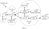
- Embodiment 2 illustrates a schematic diagram of a network architecture according to the present application, as shown in FIG. 2 .
- FIG. 2 shows a diagram of a network architecture 200 of a 5G NR system, a Long-Term Evolution (LTE) system, and a Long Term Evolution-Advanced (LTE-A) system.
- the 5G NR or LTE network architecture 200 may be referred to as a 5G System (5GS)/an Evolved Packet System (EPS) 200 or another suitable term.
- the 5GS/EPS 200 may include one or more user equipments (UEs) 201, a next-generation radio access network (NG-RAN) 202, a 5G Core Network (5GC)/an Evolved Packet Core (EPC) 210, a Home Subscriber Server (HSS)/Unified Data Management (UDM) 220, and an Internet service 230.
- UEs user equipments
- NG-RAN next-generation radio access network
- EPC Evolved Packet Core
- HSS Home Subscriber Server
- UDM Unified Data Management
- the 5GS/EPS may interconnect with other access networks, but these entities/interfaces are not shown for simplicity. As shown in the figure, the 5GS/EPS provides a packet-switched service. However, those skilled in the art will readily understand that the various concepts presented throughout the present application may be extended to a network that provides a circuit-switched service or another cellular network.
- the NG-RAN includes an NR Node B (gNB) 203 and another gNB 204.
- the gNB 203 provides termination of a user plane protocol and a control plane protocol towards the UE 201.
- the gNB 203 may be connected to the another gNB 204 via an Xn interface (for example, a backhaul).
- the gNB 203 may also be referred to as a base station, a base transceiver station, a wireless base station, a wireless transceiver, a transceiver function, a basic service set (BSS), an extended service set (ESS), a transmission and reception point (TRP), or another suitable term.
- the gNB 203 provides the UE 201 with an access point to the 5GC/EPC 210.
- Examples of the UE 201 include a cellular phone, a smart phone, a Session Initiation Protocol (SIP) phone, a laptop computer, a personal digital assistant (PDA), a satellite radio apparatus, a non-terrestrial base station communication apparatus, a satellite mobile communications apparatus, a global positioning system, a multimedia apparatus, a video apparatus, a digital audio player (such as an MP3 player), a camera, a game console, an unmanned aerial vehicle, an aircraft, a narrowband-internet of Things device, a machine type communications device, a land vehicle, an automobile, a wearable device, or any other similar functional apparatuses.
- SIP Session Initiation Protocol
- PDA personal digital assistant
- satellite radio apparatus a non-terrestrial base station communication apparatus
- a satellite mobile communications apparatus a global positioning system
- multimedia apparatus such as an MP3 player
- a digital audio player such as an MP3 player
- a camera such as an MP3 player
- game console an unmanned aerial vehicle,
- the UE 201 may also be referred, by a person skilled in the art, to as a mobile station, a subscriber station, a mobile unit, a subscriber unit, a wireless unit, a remote unit, a mobile apparatus, a wireless apparatus, a wireless communications apparatus, a remote apparatus, a mobile subscriber station, an access terminal, a mobile terminal, a wireless terminal, a remote terminal, a handset, a user agent, a mobile client, a client, or another suitable term.
- the gNB 203 is connected to the 5GC/EPC 210 via an S1/NG interface.
- the 5GC/EPC 210 includes a Mobility Management Entity (MME)/Authentication Management Field (AMF)/Session Management Function (SMF) 211, another MME/AMF/SMF 214, a Service Gateway (S-GW)/User Plane Function (UPF) 212, and a Packet Data Network Gateway (P-GW)/UPF 213.
- MME Mobility Management Entity
- AMF Access Management Field
- S-GW Service Gateway
- UPF User Plane Function
- P-GW Packet Data Network Gateway
- the MME/AMF/SMF 211 is a control node that handles signaling between the UE 201 and the 5GC/EPC 210.
- the MME/AMF/SMF 211 provides bearing and connection management.
- IP Internet Protocol
- the P-GW provides UE IP address allocation and other functions.
- the P-GW/UPF 213 is connected to the Internet service 230.
- the Internet service 230 includes an Internet protocol service corresponding to an operator, and may specifically include an Internet service, an intranet service, an IP multimedia subsystem (IMS) service, and a packet switching streaming service.
- IMS IP multimedia subsystem
- the first node in the present application includes the gNB 203.
- the second node in the present application includes the gNB 203.
- the second node in the present application includes the UE 241.
- the first node in the present application includes the UE 241.
- the second node in the present application includes the UE 201.
- the second node in the present application includes the gNB 204.
- the user equipment in the present application includes the UE 201.
- the user equipment in the present application includes the UE 241.
- the base station in the present application includes the gNB 203.
- the base station device in the present application includes the gNB 204.
- the UE 201 supports sidelink transmission.
- the UE 201 supports a PC5 interface.
- the UE 201 supports a Uu interface.
- the UE 241 supports sidelink transmission.
- the UE 241 supports a PC5 interface.
- the gNB 203 supports a Uu interface.
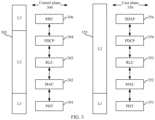
- Embodiment 3 illustrates a schematic diagram of a radio protocol architecture of each of a user plane and a control plane according to an embodiment of the present application, as shown in FIG. 3.
- FIG. 3 is a schematic diagram illustrating an embodiment of a radio protocol architecture for each of a user plane 350 and a control plane 300.
- FIG. 3 uses layer 1, layer 2, and layer 3 to display the radio protocol architecture of the control plane 300 used for a first node (UE or an RSU in V2X, an in-vehicle device, or an in-vehicle communication module) and a second node (a gNB, UE or an RSU in V2X, an in-vehicle device, or an in-vehicle communication module), or between two UEs.
- a first node UE or an RSU in V2X, an in-vehicle device, or an in-vehicle communication module
- a gNB UE or an RSU in V2X, an in-vehicle device
- the layer 1 is a lowest layer and various physical layer (PHY) signal processing functions are implemented at this layer.
- the L1 layer is referred to as PHY 301 herein.
- the layer 2 (L2 layer) 305 is disposed on the PHY 301, and responsible for a link between the first node and the second node and a link between two UEs through the PHY 301.
- the L2 layer 305 includes a Medium Access Control (MAC) sublayer 302, a Radio Link Control (RLC) sublayer 303, and a Packet Data Convergence Protocol (PDCP) sublayer 304, and these sublayers are terminated at the second node.
- MAC Medium Access Control
- RLC Radio Link Control
- PDCP Packet Data Convergence Protocol
- the PDCP sublayer 304 provides data encryption and integrity protection, and further provides cross-area movement support of the first node to the second node.
- the RLC sublayer 303 provides segmentation and reassembly of data packets, implements retransmission of a lost data packet via ARQ, and further provides repeated data packet detection and protocol error detection.
- the MAC sublayer 302 provides mapping between a logical channel and a transport channel and reuse of the logical channel, and is responsible for allocating, between first nodes, various radio resources (for example, resource blocks) in a cell.
- the MAC sublayer 302 is further responsible for a HARQ operation.
- a Radio Resource Control (RRC) sublayer 306 in the layer 3 (L3 layer) in the control plane 300 is responsible for obtaining a radio resource (namely, a radio bearer) and configuring a lower layer by using RRC signaling between the second node and the first node.
- the radio protocol architecture of the user plane 350 includes layer 1 (L1 layer) and layer 2 (L2 layer).
- a PHY layer 351, a PDCP sublayer 354 in the L2 layer 355, an RLC sublayer 353 in the L2 layer 355, and a MAC sublayer 352 in the L2 layer 355 of the radio protocol architecture, used for the first node and the second node, in the user plane 350 are substantially the same as the corresponding layers and sublayers in the control plane 300, but the PDCP sublayer 354 further provides header compression used for an upper layer data packet to reduce wireless transmission overheads.
- the L2 layer 355 in the user plane 350 further includes a Service Data Adaptation Protocol (SDAP) sublayer 356.
- SDAP sublayer 356 is responsible for mapping between QoS flows and data radio bearers (DRBs), to support service diversity.
- the first node may be provided with several upper layers above the L2 layer 355, including a network layer (for example, an IP layer) terminating at the P-GW on the network side and an application layer terminating at the other end of connection (for example, a remote UE and a server).
- a network layer for example, an IP layer
- an application layer terminating at the other end of connection (for example, a remote UE and a server).
- the radio protocol architectures in FIG. 3 are applicable to the first node in the present application.
- radio protocol architectures in FIG. 3 are applicable to the second node in the present application.
- the first information block in the present application is generated at the PHY 351.
- the first information block in the present application is generated at the MAC 352.
- the first information block in the present application is generated at the PHY 301.
- the first information block in the present application is generated at the MAC 302.
- the first information block in the present application is generated at the RRC 306.
- the first signal in the present application is generated at the PHY 351.
- the first signal in the present application is generated at the MAC 352.
- the first signal in the present application is generated at the PHY 301.
- the first signal in the present application is generated at the MAC 302.
- the first signal in the present application is generated at the RRC 306.
- Embodiment 4 illustrates a schematic diagram of a first communications device and a second communications device according to the present application, as shown in FIG. 4.
- FIG. 4 is a block diagram of a first communications device 410 and a second communications device 450 communicating with each other in an access network.
- the first communications device 410 includes a controller/processor 475, a memory 476, a receive processor 470, a transmit processor 416, a multi-antenna receive processor 472, a multi-antenna transmit processor 471, transmitters/receivers 418, and antennas 420.
- the second communications device 450 includes a controller/processor 459, a memory 460, a data source 467, a transmit processor 468, a receive processor 456, a multi-antenna transmit processor 457, a multi-antenna receive processor 458, transmitters/receivers 454, and antennas 452.
- an upper-layer data packet from a core network is provided for the controller/processor 475.
- the controller/processor 475 implements functionality of the L2 layer.
- the controller/processor 475 provides header compression, encryption, packet segmentation and reordering, multiplexing between a logical channel and a transport channel, and allocation to radio resources of the second communications device 450 based on various priority measurements.
- the controller/processor 475 is further responsible for retransmission of a lost data packet, and signaling to the second communications device 450.
- the transmit processor 416 and the multi-antenna transmit processor 471 implement various signal processing functions of the L1 layer (namely, the physical layer).
- the transmit processor 416 implements encoding and interleaving to facilitate forward error correction (FEC) at the second communications device 450, and mapping of a signal cluster based on various modulation schemes (such as binary phase shift keying (BPSK), quadrature phase shift keying (QPSK), M-phase shift keying (M-PSK), and M-quadrature amplitude modulation (M-QAM)).
- FEC forward error correction
- the multi-antenna transmit processor 471 performs digital spatial precoding on a coded and modulated symbol, including codebook-based precoding and non-codebook-based precoding, and beamforming processing, to generate one or more spatial streams.
- the transmit processor 416 maps each spatial stream to a subcarrier, multiplexes the mapped spatial stream with a reference signal (for example, a pilot signal) in time domain and/or frequency domain, and then uses inverse fast Fourier transform (IFFT) to generate a physical channel that carries a time-domain multi-carrier symbol stream. Then, the multi-antenna transmit processor 471 performs an operation of analog precoding receiving/beamforming on the time-domain multi-carrier symbol stream. Each transmitter 418 converts a baseband multi-carrier symbol stream provided by the multi-antenna transmit processor 471 into a radio frequency stream, and then provides the radio frequency stream for different antennas 420.
- a reference signal for example, a pilot signal
- IFFT inverse fast Fourier transform
- each receiver 454 receives, at the second communications device 450, a signal through its corresponding antenna 452.
- Each receiver 454 recovers information modulated onto a radio-frequency carrier, converts the radio frequency stream into a baseband multi-carrier symbol stream, and provides the baseband multi-carrier symbol stream for the receive processor 456.
- the receive processor 456 and the multi-antenna receive processor 458 implement various signal processing functions of the L1 layer.
- the multi-antenna receive processor 458 performs an operation of analog precoding receiving/beamforming on the baseband multi-carrier symbol stream from the receiver 454.
- the receive processor 456 uses a Fourier transform (FFT) to convert, from time domain to frequency domain via fast, the baseband multi-carrier symbol stream obtained after the operation of analog precoding receiving/beamforming.
- FFT Fourier transform
- a physical layer data signal and a reference signal are demultiplexed by the receive processor 456.
- the reference signal is used for channel estimation, and the data signal is recovered after multi-antenna detection performed by the multi-antenna receive processor 458, to obtain any spatial stream that uses the second communications device 450 as a destination. Symbols on each spatial stream are demodulated and recovered in the receive processor 456, and a soft decision is generated.
- the receive processor 456 then decodes and de-interleaves the soft decision to recover upper-layer data and a control signal that are transmitted by the first communications device 410 on the physical channel.
- the upper-layer data and the control signal are then provided for the controller/processor 459.
- the controller/processor 459 implements functions of the L2 layer, and may be associated with the memory 460that stores program code and data.
- the memory 460 may be referred to as a computer-readable medium.
- the controller/processor 459 provides demultiplexing between a transport channel and a logical channel, packet reassembly, decryption, header decompression, and control signal processing, to recover an upper-layer data packet from a core network.
- the upper-layer data packet is then provided for all protocol layers above the L2 layer, or various control signals for the L3 layer for processing by the L3 layer.
- an upper-layer data packet is provided for the controller/processor 459 by using the data source 467.
- the data source 467 represents all protocol layers above the L2 layer.
- the controller/processor 459 implements header compression, encryption, packet segmentation and reordering, and multiplexing between a logical channel and a transport channel based on a wireless resource, to implement L2 layer functions for the user plane and the control plane.
- the controller/processor 459 is further responsible for retransmission of a lost data packet, and signaling to the first communications device 410.
- the transmit processor 468 performs modulation, mapping, and channel encoding processing.
- the multi-antenna transmit processor 457 performs digital multi-antenna spatial precoding, including codebook-based precoding and non-codebook-based precoding, and beamforming processing. Then the transmit processor 468 modulates a generated spatial stream into a multi-carrier/single-carrier symbol stream, and the multi-carrier/single-carrier symbol stream is provided for different antennas 452 via the transmitters 454 after undergoing an analog precoding/beamforming operation in the multi-antenna transmit processor 457. Each transmitter 454 first converts a baseband symbol stream provided by the multi-antenna transmit processor 457 into a radio-frequency symbol stream, and then provides the radio-frequency symbol stream for the antennas 452.
- a function at the first communications device 410 is similar to a receiving function at the second communications device 450 described in the transmission from the first communications device 410 to the second communications device 450.
- Each receiver 418 receives a radio frequency signal through its corresponding antenna 420, converts the received radio frequency signal into a baseband signal, and provides the baseband signal for the multi-antenna receive processor 472 and the receive processor 470.
- the receive processor 470 and the multi-antenna receive processor 472 jointly implement functions of the L1 layer.
- the controller/processor 475 implements functions of the L2 layer.
- the controller/processor 475 may be associated with the memory 476 that stores program code and data.
- the memory 476 may be referred to as a computer-readable medium.
- the controller/processor 475 In the transmission from the second communications device 450 to the first communications device 410, the controller/processor 475 provides demultiplexing between a transport channel and a logical channel, packet reassembly, decryption, header decompression, and control signal processing, to recover an upper-layer data packet from UE 450.
- the controller/processor 475 may provide the upper-layer data packet to a core network.
- the first node in the present application includes the second communications device 450; and the second node in the present application includes the first communications device 410.
- the first node in the present application includes the first communications device 410; and the second node in the present application includes the second communications device 450.
- the first node in the present application includes the second communications device 450; and the second node in the present application includes the second communications device 450.
- the second communications device 450 includes: at least one controller/processor.
- the at least one controller/processor is responsible for a HARQ operation.
- the first communications device 410 includes: at least one controller/processor.
- the at least one controller/processor is responsible for a HARQ operation.
- the first communications device 410 includes: at least one controller/processor.
- the at least one controller/processor is responsible for a HARQ operation by performing error detection according to a positive acknowledgment (ACK) protocol and/or a negative acknowledgment (NACK) protocol.
- ACK positive acknowledgment
- NACK negative acknowledgment
- the second communications device 450 includes: at least one memory and at least one processor.
- the at least one memory includes a computer program code.
- the at least one memory and the computer program code are configured to be used with the at least one processor.
- the second communications device 450 is at least configured to: receive a first information block, where the first information block is used to indicate a first time-frequency resource block; perform first access detection in a first sub-band, where the first access detection includes more than one time of first type monitoring; and send the first signal in the first time-frequency resource block when a quantity of times of the first type monitoring, in the first access detection, with monitoring results indicating that a channel is idle is not less than Q1; or abstain from sending of the first signal in the first time-frequency resource block when a quantity of times of the first type monitoring, in the first access detection, with monitoring results indicating that a channel is idle is less than Q1.
- An end time of the first access detection is not later than a start time of the first time-frequency resource block, the monitoring result of one time of the first type monitoring includes a channel being idle or a channel being busy, and Q1 is a positive integer.
- the first access detection includes Q2 times of first type monitoring and Q3 times of first type monitoring, the Q2 times of first type monitoring are earlier than the Q3 times of first type monitoring in time domain, Q2 is a positive integer, and Q3 is a positive integer.
- a first multi-antenna relevant parameter is used in the Q2 times of first type monitoring, a second multi-antenna relevant parameter is used in the Q3 times of first type monitoring, and the second multi-antenna relevant parameter is different from the first multi-antenna relevant parameter.
- a quantity of times of the first type monitoring, in the Q2 times of first type monitoring, with monitoring results indicating that a channel is idle is less than Q1.
- the second communications device 450 includes: a memory storing a computer-readable instruction program.
- the computer-readable instruction program When being executed by the at least one processor, the computer-readable instruction program performs actions. The actions include: receiving a first information block, where the first information block is used to indicate a first time-frequency resource block; performing first access detection in a first sub-band, where the first access detection includes more than one time of first type monitoring; and sending the first signal in the first time-frequency resource block when a quantity of times of the first type monitoring, in the first access detection, with monitoring results indicating that a channel is idle is not less than Q1; or abstaining from sending of the first signal in the first time-frequency resource block when a quantity of times of the first type monitoring, in the first access detection, with monitoring results indicating that a channel is idle is less than Q1.
- An end time of the first access detection is not later than a start time of the first time-frequency resource block, the monitoring result of one time of the first type monitoring includes a channel being idle or a channel being busy, and Q1 is a positive integer.
- the first access detection includes Q2 times of first type monitoring and Q3 times of first type monitoring, the Q2 times of first type monitoring are earlier than the Q3 times of first type monitoring in time domain, Q2 is a positive integer, and Q3 is a positive integer.
- a first multi-antenna relevant parameter is used in the Q2 times of first type monitoring, a second multi-antenna relevant parameter is used in the Q3 times of first type monitoring, and the second multi-antenna relevant parameter is different from the first multi-antenna relevant parameter.
- a quantity of times of the first type monitoring, in the Q2 times of first type monitoring, with monitoring results indicating that a channel is idle is less than Q1.
- the first communications device 410 includes: at least one memory and at least one processor.
- the at least one memory includes a computer program code.
- the at least one memory and the computer program code are configured to be used with the at least one processor.
- the first communications device 410 is at least configured to: send a first information block, where the first information block is used to indicate a first time-frequency resource block; and monitor a first signal in the first time-frequency resource block.
- First access detection performed in a first sub-band is used to determine whether the first signal is sent.
- the first access detection includes more than one time of first type monitoring.
- the first signal is sent in the first time-frequency resource block when a quantity of times of the first type monitoring, in the first access detection, with monitoring results indicating that a channel is idle is not less than Q1; or the first signal is not sent in the first time-frequency resource block when a quantity of times of the first type monitoring, in the first access detection, with monitoring results indicating that a channel is idle is less than Q1.
- An end time of the first access detection is not later than a start time of the first time-frequency resource block, the monitoring result of one time of the first type monitoring includes a channel being idle or a channel being busy, and Q1 is a positive integer.
- the first access detection includes Q2 times of first type monitoring and Q3 times of first type monitoring, the Q2 times of first type monitoring are earlier than the Q3 times of first type monitoring in time domain, Q2 is a positive integer, and Q3 is a positive integer.
- a first multi-antenna relevant parameter is used in the Q2 times of first type monitoring
- a second multi-antenna relevant parameter is used in the Q3 times of first type monitoring
- the second multi-antenna relevant parameter is different from the first multi-antenna relevant parameter.
- a quantity of times of the first type monitoring, in the Q2 times of first type monitoring, with monitoring results indicating that a channel is idle is less than Q1.
- the first communications device 410 includes: a memory storing a computer-readable instruction program.
- the computer-readable instruction program When being executed by the at least one processor, the computer-readable instruction program performs actions. The actions include: sending a first information block, where the first information block is used to indicate a first time-frequency resource block; and monitoring a first signal in the first time-frequency resource block. First access detection performed in a first sub-band is used to determine whether the first signal is sent. The first access detection includes more than one time of first type monitoring.
- the first signal is sent in the first time-frequency resource block when a quantity of times of the first type monitoring, in the first access detection, with monitoring results indicating that a channel is idle is not less than Q1; or the first signal is not sent in the first time-frequency resource block when a quantity of times of the first type monitoring, in the first access detection, with monitoring results indicating that a channel is idle is less than Q1.
- An end time of the first access detection is not later than a start time of the first time-frequency resource block, the monitoring result of one time of the first type monitoring includes a channel being idle or a channel being busy, and Q1 is a positive integer.
- the first access detection includes Q2 times of first type monitoring and Q3 times of first type monitoring, the Q2 times of first type monitoring are earlier than the Q3 times of first type monitoring in time domain, Q2 is a positive integer, and Q3 is a positive integer.
- a first multi-antenna relevant parameter is used in the Q2 times of first type monitoring
- a second multi-antenna relevant parameter is used in the Q3 times of first type monitoring
- the second multi-antenna relevant parameter is different from the first multi-antenna relevant parameter.
- a quantity of times of the first type monitoring, in the Q2 times of first type monitoring, with monitoring results indicating that a channel is idle is less than Q1.
- At least one of the antenna 452, the receiver 454, the multi-antenna receive processor 458, the receive processor 456, the controller/processor 459, the memory 460, and the data source 467 is configured to receive the first signaling in the present application.
- At least one of the antenna 452, the receiver 454, the multi-antenna receive processor 458, the receive processor 456, the controller/processor 459, the memory 460, and the data source 467 is configured to receive the second signaling in the present application.
- At least one of the antenna 452, the receiver 454, the multi-antenna receive processor 458, the receive processor 456, the controller/processor 459, the memory 460, and the data source 467 is configured to receive the first signal in the present application.
- At least one of the antenna 420, the receiver 418, the multi-antenna receive processor 472, the receive processor 470, the controller/processor 475, and the memory 476 is configured to send the first signaling in the present application.
- At least one of the antenna 420, the receiver 418, the multi-antenna receive processor 472, the receive processor 470, the controller/processor 475, and the memory 476 is configured to send the second signaling in the present application.
- At least one of the antenna 420, the receiver 418, the multi-antenna receive processor 472, the receive processor 470, the controller/processor 475, and the memory 476 is configured to send the first signal in the present application.
- Embodiment 5 illustrates a transmission flowchart of a wireless signal according to an embodiment of the present application, as shown in FIG. 5 .
- a first node U1 communicates with a second node U2 through an air interface.
- a sequence of steps in the blocks in FIG. 5 does not represent a specific temporal sequence relationship.
- Step S11 For the first node U1 , a first information block is received in Step S11; first access detection is performed in Step S12; and a first signal is sent in Step S13.
- the first information block is sent in Step S21; and the first signal is received in Step S22.
- the first information block is used to indicate a first time-frequency resource block.
- the first access detection includes more than one time of first type monitoring.
- the first node U1 sends a first signal in the first time-frequency resource block when a quantity of times of the first type monitoring, in the first access detection, with monitoring results indicating that a channel is idle is not less than Q1.
- the first node U1 abstains from sending of the first signal in the first time-frequency resource block when a quantity of times of the first type monitoring, in the first access detection, with monitoring results indicating that a channel is idle is less than Q1.
- An end time of the first access detection is not later than a start time of the first time-frequency resource block, the monitoring result of one time of the first type monitoring includes a channel being idle or a channel being busy, and Q1 is a positive integer.
- the first access detection includes Q2 times of first type monitoring and Q3 times of first type monitoring, the Q2 times of first type monitoring are earlier than the Q3 times of first type monitoring in time domain, Q2 is a positive integer, and Q3 is a positive integer.
- a first multi-antenna relevant parameter is used in the Q2 times of first type monitoring, a second multi-antenna relevant parameter is used in the Q3 times of first type monitoring, and the second multi-antenna relevant parameter is different from the first multi-antenna relevant parameter.
- a quantity of times of the first type monitoring, in the Q2 times of first type monitoring, with monitoring results indicating that a channel is idle is less than Q1.
- the air interface between the second node U2 and the first node U1 includes a PC5 interface.
- the air interface between the second node U2 and the first node U1 includes a sidelink.
- the air interface between the second node U2 and the first node U1 includes a Uu interface.
- the air interface between the second node U2 and the first node U1 includes a cellular link.
- the air interface between the second node U2 and the first node U1 includes a radio interface between user equipment and user equipment.
- the air interface between the second node U2 and the first node U1 includes a radio interface between a base station device and user equipment.
- Embodiment 6 illustrates a schematic diagram showing time resources occupied by first access detection and a first time-frequency resource block according to an embodiment of the present application, as shown in FIG. 6 .
- a block filled with a gray background indicates a time resource included by the first access detection.
- the first access detection includes more than one time of first type monitoring; the more than one time of first type monitoring is arranged sequentially in time domain; and the first time-frequency resource block is after the first access detection in time domain.
- any two of the more than one time of first type monitoring have a same duration period.
- any two of the more than one time of first type monitoring have different duration periods.
- a duration period of any two of the more than one time of first type monitoring is one of 4 microseconds, 5 microseconds, 7 microseconds, 9 microseconds, 16 microseconds, and 25 microseconds.
- intervals between every two temporally consecutive times of the more than one time of first type monitoring are the same.
- the first access detection is a channel access procedure.
- the first access detection is a channel access procedure on an unlicensed spectrum.
- the first access detection is a Type 1 uplink channel access procedure.
- Type 1 uplink channel access procedure refers to 3GPP TS37.213.
- the first access detection is a Type 1 downlink channel access procedure.
- Type 1 downlink channel access procedure refers to 3GPP TS37.213.
- the first access detection is one time of category 4 LBT (Cat 4 LBT).
- the first type monitoring includes one time of energy detection.
- the first type monitoring includes a plurality of times of energy detection.
- the first type monitoring includes coherent detection.
- the first type monitoring includes a cyclic redundancy check (CRC).
- CRC cyclic redundancy check
- the first type monitoring includes jamming sensing.
- a duration period of the first type monitoring is a sensing slot duration.
- the sensing slot duration refer to 3GPP TS37.213.
- the first receiving set performs energy detection in the first interval.
- the first time-frequency resource block is configured to send the first signal.
- the first receiving set performs a plurality of times of energy detection in the first interval.
- the first time-frequency resource block is configured to send the first signal.
- the first information block is used to indicate a priority parameter of the first signal.
- the first information block is used to indicate a type of the first access detection.
- the first information block is used to indicate that a type of the first access detection is Cat 4 LBT.
- the first information block is used to indicate that a type of the first access detection is a Type 1 uplink access procedure.
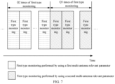
- Embodiment 7 illustrates a schematic diagram showing time resources respectively occupied by Q2 times of first type monitoring and Q3 times of first type monitoring included by first access detection and multi-antenna relevant parameters of the Q2 times of first type monitoring and the Q3 times of first type monitoring according to an embodiment of the present application, as shown in FIG. 7 .
- a block filled with horizontal stripes denotes a schematic diagram of a time domain resource of Q2 times of first type monitoring performed by using a first multi-antenna relevant parameter
- a block filled with diagonal stripes denotes a schematic diagram of a time domain resource of Q3 times of first type monitoring performed by using a second multi-antenna relevant parameter.
- the Q2 times of first type monitoring are arranged successively in time domain; the Q3 times of first type monitoring are arranged successively in time domain; and the Q3 times of first type monitoring are after the Q2 times of first type monitoring in time domain.
- a total quantity of times of the first type monitoring, in the Q2 times of first type monitoring and the Q3 times of first type monitoring, with monitoring results indicating that a channel is idle is Q1.
- a total quantity of times of the first type monitoring, in the Q2 times of first type monitoring and the Q3 times of first type monitoring, with monitoring results indicating that a channel is idle is less than Q1.
- Q3 is equal to 1.
- Q3 is greater than 1.
- the first receiving set uses the second multi-antenna relevant parameter to perform the Q3 times of first type monitoring; or when the first condition set is unsatisfied, the first receiving set uses the first multi-antenna relevant parameter to perform the Q3 times of first type monitoring.
- the first condition set includes: a monitoring result of the last one of the Q2 times of first type monitoring indicating that a channel is busy.
- the first condition set includes: a quantity of times of the first type monitoring, in the Q2 times of first type monitoring, with monitoring results indicating that a channel is busy being greater than a first quantity threshold that is a positive integer.
- the first condition set includes: a quantity of times of the first type monitoring, in the Q2 times of first type monitoring, with monitoring results indicating that a channel is busy being not less than a first quantity threshold that is a positive integer.
- the first condition set includes: the first node being configured with the second multi-antenna relevant parameter.
- the first access detection includes dynamic frequency selection (DFS).
- DFS dynamic frequency selection
- a monitoring result of the first type monitoring indicates that a channel is busy; or when the strength of the signal in the first sub-band is less than the candidate power threshold, a monitoring result of the first type monitoring indicates that a channel is idle.
- the candidate power threshold is related to the multi-antenna relevant parameter of the first type monitoring.
- a unit of the candidate power threshold is dBm.
- the candidate power threshold is defined in a radiation interface boundary (RIB).
- RIB radiation interface boundary
- the candidate power threshold is defined in an antenna connector.
- the candidate power threshold is defined in Over The Air (OTA).
- OTA Over The Air
- a unit of the candidate power threshold is watt.
- the candidate power threshold is the first power threshold
- the candidate power threshold is the second power threshold.
- the first power threshold is associated with the first multi-antenna relevant parameter and used to determine the monitoring results of the Q2 times of first type monitoring;
- the second power threshold is associated with the second multi-antenna relevant parameter and used to determine the monitoring results of the Q3 times of first type monitoring; and the second power threshold is not less than the first power threshold.
- the first type monitoring includes measurement of a reference signal.
- the first type monitoring includes measurement of a CSI-RS.
- the first type monitoring includes measurement of an SSB.
- the first type monitoring is used to determine reference signal received power (RSRP).
- RSRP reference signal received power
- the first type monitoring is used to determine a received signal strength indicator (RSSI).
- RSSI received signal strength indicator
- the first type monitoring is used to determine a signal to interference and noise ratio (SINR).
- SINR signal to interference and noise ratio
- the first type monitoring is used to determine a channel quality indicator (CQI).
- CQI channel quality indicator
- the first type monitoring includes measurement of a beam.
- the first type monitoring includes measurement of CSI.
- the first type monitoring includes determining beam measurement.
- the first type monitoring includes determining whether to perform beam switching.
- a quantity of times of the first type monitoring, in the Q2 times of first type monitoring, with monitoring results indicating that a channel is configured to determine the second multi-antenna relevant parameter is configured to determine the second multi-antenna relevant parameter.
- the quantity of times of the first type monitoring, in the Q2 times of first type monitoring, with monitoring results indicating that a channel is configured to determine the second multi-antenna relevant parameter from N multi-antenna relevant parameters; the second multi-antenna relevant parameter is one of the N multi-antenna relevant parameters; and N is a positive integer greater than 1.
- a first integer is the quantity of times of the first type monitoring, in the Q2 times of first type monitoring, with monitoring results indicating that a channel is idle; the first integer is used to determine a first coefficient; and the first coefficient belongs to a first value range.
- the N multi-antenna relevant parameters are in a one-to-one correspondence with N value ranges, respectively; and the second multi-antenna relevant parameter is a multi-antenna relevant parameter, in the N multi-antenna relevant parameters, corresponding to the first value range.
- the first coefficient is determined based on a value obtained after dividing the first integer by Q2.
- the first coefficient is equal to the value obtained after dividing the first integer by Q2.
- the first coefficient is linearly related to the value obtained after dividing the first integer by Q2.
- the first coefficient is determined based on a value obtained after dividing the first integer by Q1.
- the first coefficient is equal to the value obtained after dividing the first integer by Q1.
- the first coefficient is linearly related to the value obtained after dividing the first integer by Q1.
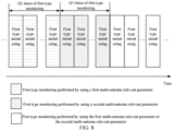
- Embodiment 8 illustrates a schematic diagram showing time resources respectively occupied by remaining times of first type monitoring, included by first access detection, other than Q2 times of first type monitoring and Q3 times of first type monitoring and multi-antenna relevant parameters of the remaining times of first type monitoring according to an embodiment of the present application, as shown in FIG. 8 .
- FIG. 8 illustrates a schematic diagram showing time resources respectively occupied by remaining times of first type monitoring, included by first access detection, other than Q2 times of first type monitoring and Q3 times of first type monitoring and multi-antenna relevant parameters of the remaining times of first type monitoring according to an embodiment of the present application, as shown in FIG. 8 .
- FIG. 8 illustrates a schematic diagram showing time resources respectively occupied by remaining times of first type monitoring, included by first access detection, other than Q2 times of first type monitoring and Q3 times of first type monitoring and multi-antenna relevant parameters of the remaining times of first type monitoring according to an embodiment of the present application, as shown in FIG. 8 .
- a block filled with horizontal stripes denotes a schematic diagram of a time domain resource of Q2 times of first type monitoring performed by using a first multi-antenna relevant parameter
- a block filled with diagonal stripes denotes a schematic diagram of a time domain resource of Q3 times of first type monitoring performed by using a second multi-antenna relevant parameter
- a block filled with white denotes a schematic diagram of a time domain resource occupied by remaining times of first type monitoring, performed by using the first or second multi-antenna relevant parameter, other than the Q2 times of first type monitoring and the Q3 times of first type monitoring.
- the Q2 times of first type monitoring are arranged successively in time domain; the Q3 times of first type monitoring are arranged successively in time domain; the Q3 times of first type monitoring are after the Q2 times of first type monitoring in time domain; and a positive integer quantity of first type monitoring exist after the Q3 times of first type monitoring.
- the Q2 times of first type monitoring, the Q3 times of first type monitoring, and the remaining times of first type monitoring other than the Q2 times of first type monitoring and the Q3 times of first type monitoring are all of first type monitoring included by the first access detection.
- the Q2 times of first type monitoring, the Q3 times of first type monitoring, and the remaining times of first type monitoring other than the Q2 times of first type monitoring and the Q3 times of first type monitoring are some of first type monitoring included by the first access detection.
- a total quantity of times of the first type monitoring, among the Q2 times of first type monitoring, the Q3 times of first type monitoring, and the remaining times of first type monitoring other than the Q2 times of first type monitoring and the Q3 times of first type monitoring, with monitoring results indicating that a channel is idle is Q1.
- a total quantity of times of the first type monitoring, among the Q2 times of first type monitoring, the Q3 times of first type monitoring, and the remaining times of first type monitoring other than the Q2 times of first type monitoring and the Q3 times of first type monitoring, with monitoring results indicating that a channel is idle is less than Q1.
- the first receiving set uses the second multi-antenna relevant parameter to perform the remaining times of first type monitoring other than the Q2 times of first type monitoring and the Q3 times of first type monitoring; or when the second condition set is unsatisfied, the first receiving set uses the first multi-antenna relevant parameter to perform the remaining times of first type monitoring other than the Q2 times of first type monitoring and the Q3 times of first type monitoring.
- the first receiving set uses the second multi-antenna relevant parameter to perform the remaining times of first type monitoring other than the Q2 times of first type monitoring and the Q3 times of first type monitoring; or when the second condition set is unsatisfied, the first receiving set independently selects the first multi-antenna relevant parameter or the second multi-antenna relevant parameter to perform the remaining times of first type monitoring other than the Q2 times of first type monitoring and the Q3 times of first type monitoring.
- the sentence "the first receiving set independently selects the first multi-antenna relevant parameter or the second multi-antenna relevant parameter to perform the remaining times of first type monitoring other than the Q2 times of first type monitoring and the Q3 times of first type monitoring" includes: the first receiving set independently selects the first multi-antenna relevant parameter or the second multi-antenna relevant parameter based on a first measure to perform the remaining times of first type monitoring other than the Q2 times of first type monitoring and the Q3 times of first type monitoring.
- the first measure includes a channel measurement result in the first sub-band.
- the first measure includes a channel occupancy ratio in the first sub-band.
- the first measure includes a channel vacancy ratio in the first sub-band.
- the first measure includes interference intensity measurement in the first sub-band.
- the first measure includes a modulation and coding scheme of the first signal.
- the first measure includes a multi-antenna relevant parameter of the first signal; and the multi-antenna relevant parameter of the first signal includes a QCL association relationship between the first signal and a reference signal.
- the first measure includes a multi-antenna relevant parameter of the first signal; and the multi-antenna relevant parameter of the first signal includes a QCL association relationship between a reference signal included by the first signal and another reference signal.
- the second condition set includes: all monitoring results of the Q3 times of first type monitoring indicating that a channel is idle.
- the second condition set includes: a quantity of times of the first type monitoring, in the Q3 times of first type monitoring, with monitoring results indicating that a channel is idle being greater than a second quantity threshold that is a positive integer.
- the second condition set includes: a quantity of times of the first type monitoring, in the Q3 times of first type monitoring, with monitoring results indicating that a channel is idle being not less than a second quantity threshold that is a positive integer.
- a value of Q3 is equal to 1.
- a value of Q3 is greater than 1.
- Embodiment 9 illustrates a schematic diagram showing widths of a first receive beam and a second receive beam of the first node according to an embodiment of the present application, as shown in FIG. 9 .
- widths of the first receive beam and the second receive beam are denoted by two different ellipses.
- the first multi-antenna relevant parameter in the present application includes the first receive beam; and the second multi-antenna relevant parameter in the present application includes the second receive beam.
- an interference node exists in a coverage range of the first receive beam. When the interference node starts to send a signal, a monitoring result of the first type monitoring performed by using the first receive beam indicates that a channel is busy.
- a monitoring result of the first type monitoring performed by using the second receive beam indicates that a channel is idle. Therefore, in a process of the first access detection, if an interference node appears and causes failure of the first type monitoring, switching from the first receive beam to the second receive beam helps improve a success probability of access detection.
- the second multi-antenna relevant parameter is spatially associated with the first multi-antenna relevant parameter.
- the second multi-antenna relevant parameter and the first multi-antenna relevant parameter belongs to a same multi-antenna relevant parameter set, and the multi-antenna relevant parameter set includes a plurality of multi-antenna relevant parameters.
- a spatial direction of the second multi-antenna relevant parameter is a sub-set of a spatial direction of the first multi-antenna relevant parameter.
- the first multi-antenna relevant parameter includes a first spatial reception filter
- the second multi-antenna relevant parameter includes a second spatial reception filter
- a spatial direction of the first spatial reception filter includes a spatial direction of the second spatial reception filter
- the first multi-antenna relevant parameter includes an omnidirectional reception filter; and the second multi-antenna relevant parameter includes a directional reception filter.
- the first multi-antenna relevant parameter includes a quasi-omni directional reception filter; and the second multi-antenna relevant parameter includes a directional reception filter.
- the first multi-antenna relevant parameter includes an omnidirectional receive beam; and the second multi-antenna relevant parameter includes a directional receive beam.
- the first multi-antenna relevant parameter includes a quasi-omni directional receive beam; and the second multi-antenna relevant parameter includes a directional receive beam.
- the first type monitoring performed by using the first multi-antenna relevant parameter includes performing omnidirectional LBT.
- the first type monitoring performed by using the first multi-antenna relevant parameter includes performing quasi-omni directional LBT.
- the first type monitoring performed by using the second multi-antenna relevant parameter includes performing directional LBT.
- a multi-antenna relevant parameter of the first signal is used to determine the second multi-antenna relevant parameter.
- the multi-antenna relevant parameter of the first signal includes a transmission spatial filter of the first signal; the second multi-antenna relevant parameter includes a reception spatial filter; and a spatial direction of the transmission spatial filter of the first signal is within a spatial direction of the reception spatial filter included by the second multi-antenna relevant parameter.
- the multi-antenna relevant parameter of the first signal includes a transmission spatial filter of the first signal; the second multi-antenna relevant parameter includes a reception spatial filter; and a spatial direction of the transmission spatial filter of the first signal is the same as a spatial direction of the reception spatial filter included by the second multi-antenna relevant parameter.
- the multi-antenna relevant parameter of the first signal is the same as the second multi-antenna relevant parameter.
- the multi-antenna relevant parameter of the first signal and the second multi-antenna relevant parameter are associated with a same reference signal.
- a reference signal associated with the multi-antenna relevant parameter of the first signal and a reference signal associated with the second multi-antenna relevant parameter have a spatial association relationship.
- a reference signal associated with the multi-antenna relevant parameter of the first signal and a reference signal associated with the second multi-antenna relevant parameter have a QCL relationship.
- the multi-antenna relevant parameter of the first signal includes a transmission spatial filter of the first signal; the first multi-antenna relevant parameter includes a reception spatial filter; and a spatial direction of the transmission spatial filter of the first signal is included in a spatial direction of the reception spatial filter included by the first multi-antenna relevant parameter.
- the multi-antenna relevant parameter of the first signal includes a transmission spatial filter of the first signal; the first multi-antenna relevant parameter includes a reception spatial filter; and a spatial direction of the transmission spatial filter of the first signal is the same as a spatial direction of the reception spatial filter included by the first multi-antenna relevant parameter.
- the multi-antenna relevant parameter of the first signal is the same as the first multi-antenna relevant parameter.
- the multi-antenna relevant parameter of the first signal and the first multi-antenna relevant parameter are associated with a same reference signal.
- a reference signal associated with the multi-antenna relevant parameter of the first signal and a reference signal associated with the first multi-antenna relevant parameter have a spatial association relationship.
- a reference signal associated with the multi-antenna relevant parameter of the first signal and a reference signal associated with the first multi-antenna relevant parameter have a QCL relationship.
- Embodiment 10 illustrates a schematic diagram of first type channel sensing according to an embodiment of the present application, as shown in FIG. 10 .
- the first access detection in the present application includes the first type channel sensing.
- the first type monitoring in the present application includes the energy detection.
- the first type channel sensing includes performing a plurality of times of energy detection in a plurality of time sub-pools in the first sub-band, to obtain a plurality of detection values.
- a wireless signal is sent in the first sub-band when and only when Q1 of the plurality of detection values are less than a first sensing threshold, and Q1 is a positive integer.
- a process of the plurality of times of energy detection may be described by using a flowchart in FIG. 10 .
- the first node or the second node is in an idle state in Step S1001; whether sending is required is determined in Step S1002; energy detection is performed in a defer duration in Step S1003; whether all sensing slot durations in the defer duration are idle is determined in Step S1004; if all the sensing slot durations are idle, a first counter is set to Q1 in Step S1005; or if all the sensing slot durations are not idle, the process returns to Step S1004; whether the first counter is 0 is determined in Step S1006; if the first counter is 0, a wireless signal is sent in the first sub-band in the present application in Step S1007; or if the first counter is not 0, energy detection is performed in an additional sensing slot duration in Step S1008; whether the additional sensing slot duration is idle is determined in Step S1009; and if the additional sensing slot duration is idle, 1 is subtracted from the first counter in Step S1010, and then the process returns to Step S1006; or if the additional
- any sensing slot duration in a given time duration includes one of the plurality of time sub-pools; and the given time duration is any duration of all defer durations, all additional sensing slot durations, and all additional defer durations in FIG. 10 .
- performing energy detection in a given time duration is: performing the energy detection in all sensing slot durations in the given time duration; and the given time duration is any duration of all defer durations, all additional sensing slot durations, and all additional defer durations in FIG. 10 .
- determining through energy detection that a given time duration is idle is: determining through energy detection that all the sensing slot durations included in the given duration are idle; and the given time duration is any duration of all defer durations, all additional sensing slot durations, and all additional defer durations in FIG. 10 .
- determining through energy detection that a given sensing slot duration is idle is: sensing, in a given time unit by the first node, powers of all wireless signals in the first sub-band, and averaging the powers by time; an obtained receiving power is less than the first sensing threshold; and the given time unit is a persistent time segment in the given sensing slot duration.
- a duration period of the given time unit is not less than 4 microseconds.
- determining through energy detection that a given sensing slot duration is idle is: sensing, in a given time unit by the first node, energies of all wireless signals in the first sub-band, and averaging the energies by time; an obtained receiving energy is less than the first sensing threshold; and the given time unit is a persistent time segment in the given sensing slot duration.
- a duration period of the given time unit is not less than 4 microseconds.
- determining through energy detection that a given sensing slot duration is idle is: performing, by the first node, the energy detection in a time sub-pool included by the given sensing slot duration; an obtained detection value is less than the first sensing threshold; the time sub-pool belongs to the plurality of time sub-pools; and the detection value belongs to the plurality of detection values.
- performing energy detection in a given time duration is: performing the energy detection in all time sub-pools in the given time duration; the given time duration is any duration of all defer durations, all additional sensing slot durations, and all additional defer durations in FIG. 10 ; and all the time sub-pools belong to the plurality of time sub-pools.
- determining through energy detection that a given time duration is idle is: performing the energy detection in all time sub-pools included in the given time duration; all obtained detection values are less than the first sensing threshold; the given time duration is any duration of all defer durations, all additional sensing slot durations, and all additional defer durations in FIG. 10 ; all the time sub-pools belong to the plurality of time sub-pools; and the detection values belong to the plurality of detection values.
- a duration period of a defer duration is 16 microseconds plus M2 9 microseconds; and M2 is a positive integer.
- a defer duration includes (M1+1) time sub-pools of the plurality of time sub-pools; and M1 is a positive integer.
- a priority class corresponding to the first signal in the present application is used to determine M1.
- the priority class is a channel access priority class.
- the channel access priority class refers to 3GPP TS37.213.
- M2 is one of 1, 2, 3, and 7.
- the plurality of times of energy detection are used to determine whether the first sub-band is idle.
- the plurality of times of energy detection are used to determine whether the first sub-band can be used by the first node in transmission of a wireless signal.
- the plurality of times of energy detection are used to determine whether the first sub-band can be used by the first node in transmission of a wireless signal that is spatially associated with the plurality of times of energy detection.
- the plurality of times of energy detection is energy detection in LBT.
- LBT For a specific definition of LBT, refer to 3GPP TS37.213.
- the plurality of times of energy detection is energy detection in CCA.
- CCA For a specific definition of CCA, refer to 3GPP TR36.889.
- any one of the plurality of times of energy detection is implemented in a manner defined in 3GPP TS37.213.
- any one of the plurality of times of energy detection is implemented by performing energy detection in Wi-Fi.
- any one of the plurality of times of energy detection is implemented by measuring an RSSI.
- any one of the plurality of times of energy detection is implemented in an energy detection manner in LTE LAA.
- all units of the plurality of times of energy detection are dBm.
- all units of the plurality of times of energy detection are mW.
- all units of the plurality of times of energy detection are Joule.
- a unit of the first sensing threshold is dBm.
- a unit of the first sensing threshold is mW.
- a unit of the first sensing threshold is Joule.
- the first sensing threshold is less than or equal to -72 dBm.
- the first sensing threshold is any value less than or equal to a first given value.
- the first given value is predefined.
- the first given value is configured through higher-layer signaling; and the first node is user equipment.
- the first type included in the first candidate type set in the present application includes the first candidate channel sensing operation.
- the first type monitoring in the present application includes category 2 channel sensing.
- channel sensing in the present application includes category 2 channel sensing.
- an operation of the category 2 channel sensing includes separately performing Q4 times of energy detection in a second time window of the first sub-band, to obtain Q4 detection values; and Q4 is a positive integer.
- the first sub-band is used to send a wireless signal when and only when Q5 of the Q4 detection values are less than the first sensing threshold; and Q5 is a positive integer not greater than Q4.
- a length of the second time window is predefined.
- the length of the second time window is one of 9 microseconds, 16 microseconds, 25 microseconds, 5 microseconds, 8 microseconds, and 13 microseconds.
- Embodiment 11 illustrates a schematic diagram of a time-domain relationship among a plurality of times of first type monitoring included by first access detection, a first time-frequency resource block, and a channel occupancy time according to an embodiment of the present application, as shown in FIG. 11 .
- the first access detection includes more than one time of first type monitoring.
- the more than one time of first type monitoring is arranged sequentially in time domain; the first time-frequency resource block is after the first access detection in time domain; the first time-frequency resource block includes a second information block; and the channel occupancy time is after the second time-frequency resource block in time domain.
- the channel occupancy time includes channel occupancy time (COT).
- COT channel occupancy time
- the channel occupancy time includes part of the COT.
- the second information block includes UCI.
- the second information block includes UCI transmitted on a PUSCH.
- the second information block includes configured grant-uplink control information (CG-UCI).
- CG-UCI configured grant-uplink control information
- the first signal includes a second information block; and the second information block is used to indicate that the second multi-antenna relevant parameter is used in the first access detection.
- the second information block is used to indicate the second multi-antenna relevant parameter.
- the second multi-antenna relevant parameter belongs to a first multi-antenna relevant parameter group; and the first multi-antenna relevant parameter group includes N multi-antenna relevant parameters.
- the first multi-antenna relevant parameter belongs to the first multi-antenna relevant parameter group.
- the second information block is used to indicate the second multi-antenna relevant parameter from the N multi-antenna relevant parameters.
- no channel occupancy time after the first time window is shared to a receiver of the first signal; and a time domain resource occupied by the first signal belongs to the first time window.
- channel occupancy time after the first time window is shared to a receiver of the first signal; and a time domain resource occupied by the first signal belongs to the first time window.
- the first time window includes a time domain resource occupied by a signal sent by the receiver of the first signal to the first node; the time domain resource occupied by the signal sent by the receiver of the first signal to the first node does not exceed M multi-carrier symbols; and M is a positive integer.
- a value of M is one of 1, 2, 4, 8, and 16.
- the signal sent by the receiver of the first signal to the first node includes control information.
- the signal sent by the receiver of the first signal to the first node includes Hybrid Automatic Repeat Request-ACKnowledgment (HARQ-ACK) information.
- HARQ-ACK Hybrid Automatic Repeat Request-ACKnowledgment
- Embodiment 12 illustrates a structural block diagram of a processing apparatus used in a first node, as shown in FIG. 12 .
- the first node 1200 includes a first receiving set 1201 and a first transmitting set 1202.
- the first receiving set 1201 includes at least one of the antenna 452, the transmitter/receiver 454, the multi-antenna receive processor 458, the receive processor 456, the controller/processor 459, the memory 460, and the data source 467 in FIG. 4 of the present application.
- the first transmitting set 1202 includes at least one of the antenna 420, the transmitter/receiver 418, the multi-antenna transmit processor 471, the transmit processor 416, the controller/processor 475, and the memory 476 in FIG. 4 of the present application.
- the first receiving set 1201 is configured to receive a first information block; the first information block is used to indicate a first time-frequency resource block; the first receiving set 1201 is configured to perform first access detection in a first sub-band; the first access detection includes more than one time of first type monitoring; the first transmitting set 1202 is configured to: send a first signal in the first time-frequency resource block when a quantity of times of the first type monitoring, in the first access detection, with monitoring results indicating that a channel is idle is not less than Q1; or abstain from sending of the first signal in the first time-frequency resource block when a quantity of times of the first type monitoring, in the first access detection, with monitoring results indicating that a channel is idle is less than Q1.
- An end time of the first access detection is not later than a start time of the first time-frequency resource block; the monitoring result of one time of the first type monitoring includes a channel being idle or a channel being busy; and Q1 is a positive integer.
- the first access detection includes Q2 times of first type monitoring and Q3 times of first type monitoring, the Q2 times of first type monitoring are earlier than the Q3 times of first type monitoring in time domain, Q2 is a positive integer, and Q3 is a positive integer.
- a first multi-antenna relevant parameter is used in the Q2 times of first type monitoring, a second multi-antenna relevant parameter is used in the Q3 times of first type monitoring, and the second multi-antenna relevant parameter is different from the first multi-antenna relevant parameter.
- a quantity of times of the first type monitoring, in the Q2 times of first type monitoring, with monitoring results indicating that a channel is idle is less than Q1.
- the first node 1200 is user equipment.
- the first node 1200 is a relay node.
- the first node 1200 is a base station.
- the first node 1200 is a vehicle-mounted communications device.
- the first node 1200 is user equipment supporting V2X communication.
- the first node 1200 is a relay node supporting V2X communication.
- the first node 1200 is a base station device supporting IAB.
- Embodiment 13 illustrates a structural block diagram of a processing apparatus used in a first node, as shown in FIG. 13 .
- a second node 1300 includes a second transmitting set 1301 and a second receiving set 1302.
- the second transmitting set 1301 includes at least one of the antenna 420, the transmitter/receiver 418, the multi-antenna transmit processor 471, the transmit processor 416, the controller/processor 475, and the memory 476 in FIG. 4 of the present application.
- the second receiving set 1302 includes at least one of the antenna 452, the transmitter/receiver 454, the multi-antenna receive processor 458, the receive processor 456, the controller/processor 459, the memory 460, and the data source 467 in FIG. 4 of the present application.
- the second transmitting set 1301 is configured to send a first information block; the first information block is used to indicate a first time-frequency resource block; and the second receiving set 1302 is configured to monitor a first signal in the first time-frequency resource block.
- First access detection performed in a first sub-band is used to determine whether the first signal is sent.
- the first access detection includes more than one time of first type monitoring.
- the first signal is sent in the first time-frequency resource block when a quantity of times of the first type monitoring, in the first access detection, with monitoring results indicating that a channel is idle is not less than Q1; or the first signal is not sent in the first time-frequency resource block when a quantity of times of the first type monitoring, in the first access detection, with monitoring results indicating that a channel is idle is less than Q1.
- An end time of the first access detection is not later than a start time of the first time-frequency resource block, the monitoring result of one time of the first type monitoring includes a channel being idle or a channel being busy, and Q1 is a positive integer.
- the first access detection includes Q2 times of first type monitoring and Q3 times of first type monitoring, the Q2 times of first type monitoring are earlier than the Q3 times of first type monitoring in time domain, Q2 is a positive integer, and Q3 is a positive integer.
- a first multi-antenna relevant parameter is used in the Q2 times of first type monitoring
- a second multi-antenna relevant parameter is used in the Q3 times of first type monitoring
- the second multi-antenna relevant parameter is different from the first multi-antenna relevant parameter.
- a quantity of times of the first type monitoring, in the Q2 times of first type monitoring, with monitoring results indicating that a channel is idle is less than Q1.
- the first power threshold is associated with the first multi-antenna relevant parameter and used to determine the monitoring results of the Q2 times of first type monitoring; a second power threshold is associated with the second multi-antenna relevant parameter and used to determine the monitoring results of the Q3 times of first type monitoring; and the second power threshold is not less than the first power threshold.
- the second multi-antenna relevant parameter is spatially associated with the first multi-antenna relevant parameter.
- a multi-antenna relevant parameter of the first signal is used to determine the second multi-antenna relevant parameter.
- a priority parameter of the first signal is used to determine Q1.
- the first signal includes a second information block; and the second information block is used to indicate that the second multi-antenna relevant parameter is used in the first access detection.
- the monitoring results of the Q3 times of first type monitoring are used to determine, from the first multi-antenna relevant parameter and the second multi-antenna relevant parameter, a multi-antenna relevant parameter for performing remaining times of first type monitoring, in the first access detection, other than the Q2 times of first type monitoring and the Q3 times of first type monitoring.
- the second node 1300 is user equipment.
- the second node 1300 is a relay node.
- the second node 1300 is a base station.
- the second node 1300 is a vehicle-mounted communications device.
- the second node 1300 is user equipment supporting V2X communication.
- the second node 1300 is a relay node supporting V2X communication.
- the second node 1300 is a base station device supporting IAB.
- each module unit in the foregoing embodiments may be implemented in a form of hardware, or may be implemented in a form of a software function module, and the present application is not limited to any specific form of a combination of hardware and software.
- the first node in the present application includes, but is not limited to, wireless communications devices such as a mobile phone, a tablet computer, a notebook, a prepaid Internet card, a low-power device, an eMTC device, an NB-IoT device, an in-vehicle communications device, an aircraft, an airplane, an unmanned aerial vehicle, and a remote control airplane.
- wireless communications devices such as a mobile phone, a tablet computer, a notebook, a prepaid Internet card, a low-power device, an eMTC device, an NB-IoT device, an in-vehicle communications device, an aircraft, an airplane, an unmanned aerial vehicle, and a remote control airplane.
- the second node in the present application includes, but is not limited to, wireless communications devices such as a mobile phone, a station, or network side device in the present application includes, but is not limited to, wireless communications devices such as a macro cell base station, a micro cell base station, a home base station, a relay base station, an eNB, a gNB, a TRP, a GNSS, a relay satellite, a satellite base station, and an air base station.
- wireless communications devices such as a macro cell base station, a micro cell base station, a home base station, a relay base station, an eNB, a gNB, a TRP, a GNSS, a relay satellite, a satellite base station, and an air base station.
Landscapes
- Engineering & Computer Science (AREA)
- Signal Processing (AREA)
- Computer Networks & Wireless Communication (AREA)
- Mobile Radio Communication Systems (AREA)
Claims (10)
- Ein erster Knoten (1200), der konfiguriert ist, um für drahtlose Kommunikation verwendet zu werden, beinhaltend:eine erste Empfangseinheit (1201), die konfiguriert ist, um einen ersten Informationsblock zu empfangen, wobei der erste Informationsblock verwendet wird, um einen ersten Zeit-Frequenz-Ressourcenblock anzugeben; undwobei die erste Empfangseinheit (1201) konfiguriert ist, um eine erste Zugriffserkennung in einem ersten Teilband durchzuführen, wobei die erste Zugriffserkennung mehr als eine Zeit einer Überwachung ersten Typs beinhaltet; undeine erste Übertragungseinheit (1202), die für Folgendes konfiguriert ist: Senden eines ersten Signals in dem ersten Zeit-Frequenz-Ressourcenblock, wenn eine Anzahl von Zeiten der Überwachung ersten Typs, in der ersten Zugriffserkennung, wobei Überwachungsergebnisse angeben, dass ein Kanal frei ist, nicht kleiner als Q1 ist; oderVerzichten auf das Senden eines ersten Signals in dem ersten Zeit-Frequenz-Ressourcenblock, wenn eine Anzahl von Zeiten der Überwachung ersten Typs, in der ersten Zugriffserkennung, wobei Überwachungsergebnisse angeben, dass ein Kanal frei ist, kleiner als Q1 ist,wobei eine Endzeit der ersten Zugriffserkennung nicht später als eine Startzeit des ersten Zeit-Frequenz-Ressourcenblocks ist, wobei das Überwachungsergebnis einer Zeit der Überwachung ersten Typs beinhaltet, dass ein Kanal frei ist oder ein Kanal belegt ist, und Q1 eine positive ganze Zahl ist; die erste Zugriffserkennung Q2 Zeiten einer Überwachung ersten Typs und Q3 Zeiten einer Überwachung ersten Typs beinhaltet, wobei die Q2 Zeiten einer Überwachung ersten Typs im Zeitbereich früher sind als die Q3 Zeiten einer Überwachung ersten Typs, wobei Q2 eine ganze positive Zahl ist und Q3 eine ganze positive Zahl ist; ein erster multiantennenrelevanter Parameter in den Q2 Zeiten einer Überwachung ersten Typs verwendet wird, ein zweiter multiantennenrelevanter Parameter in den Q3 Zeiten einer Überwachung ersten Typs verwendet wird und sich der zweite multiantennenrelevante Parameter von dem ersten multiantennenrelevanten Parameter unterscheidet; und eine Anzahl von Zeiten der Überwachung ersten Typs, in den Q2 Zeiten einer Überwachung ersten Typs, wobei Überwachungsergebnisse angeben, dass ein Kanal frei ist, kleiner als Q1 ist.
- Erster Knoten (1200) gemäß Anspruch 1, wobei eine erste Leistungsschwelle mit dem ersten multiantennenrelevanten Parameter assoziiert ist und verwendet wird, um die Überwachungsergebnisse der Q2 Zeiten einer Überwachung ersten Typs zu bestimmen; eine zweite Leistungsschwelle mit dem zweiten multiantennenrelevanten Parameter assoziiert ist und verwendet wird, um die Überwachungsergebnisse der Q3 Zeiten einer Überwachung ersten Typs zu bestimmen; und die zweite Leistungsschwelle nicht kleiner als die erste Leistungsschwelle ist.
- Erster Knoten (1200) gemäß Anspruch 1 oder 2, wobei der zweite multiantennenrelevante Parameter mit dem ersten multiantennenrelevanten Parameter räumlich assoziiert ist.
- Erster Knoten (1200) gemäß einem der Ansprüche 1 bis 3, wobei ein multiantennenrelevanter Parameter des ersten Signals verwendet wird, um den zweiten multiantennenrelevanten Parameter zu bestimmen.
- Erster Knoten (1200) gemäß einem der Ansprüche 1 bis 4, wobei ein Prioritätsparameter des ersten Signals verwendet wird, um Q1 zu bestimmen.
- Erster Knoten (1200) gemäß einem der Ansprüche 1 bis 5, wobei das erste Signal einen zweiten Informationsblock beinhaltet und der zweite Informationsblock verwendet wird, um anzugeben, dass der zweite multiantennenrelevante Parameter in der ersten Zugriffserkennung verwendet wird.
- Erster Knoten (1200) gemäß einem der Ansprüche 1 bis 6, wobei die Überwachungsergebnisse der Q3 Zeiten einer Überwachung ersten Typs verwendet werden, um anhand des ersten multiantennenrelevanten Parameters und des zweiten multiantennenrelevanten Parameters einen multiantennenrelevanten Parameter für das Durchführen einer verbleibenden Überwachung ersten Typs, in der ersten Zugriffserkennung, zu bestimmen, die nicht die Q2 Zeiten einer Überwachung ersten Typs und die Q3 Zeiten einer Überwachung ersten Typs ist.
- Ein Verfahren, das durch einen ersten Knoten, der für drahtlose Kommunikation verwendet wird, durchgeführt wird, beinhaltend:Empfangen (S11) eines ersten Informationsblocks, wobei der erste Informationsblock verwendet wird, um einen ersten Zeit-Frequenz-Ressourcenblock anzugeben;Durchführen (S12) einer ersten Zugriffserkennung in einem ersten Teilband, wobei die erste Zugriffserkennung mehr als eine Zeit einer Überwachung ersten Typs beinhaltet; undSenden (S13) eines ersten Signals in dem ersten Zeit-Frequenz-Ressourcenblock, wenn eine Anzahl von Zeiten der Überwachung ersten Typs, in der ersten Zugriffserkennung, wobei Überwachungsergebnisse angeben, dass ein Kanal frei ist, nicht kleiner als Q1 ist; oder Verzichten auf das Senden eines ersten Signals in dem ersten Zeit-Frequenz-Ressourcenblock, wenn eine Anzahl von Zeiten der Überwachung ersten Typs, in der ersten Zugriffserkennung, wobei Überwachungsergebnisse angeben, dass ein Kanal frei ist, kleiner als Q1 ist, wobei eine Endzeit der ersten Zugriffserkennung nicht später als eine Startzeit des ersten Zeit-Frequenz-Ressourcenblocks ist, wobei das Überwachungsergebnis einer Zeit der Überwachung ersten Typs beinhaltet, dass ein Kanal frei ist oder ein Kanal belegt ist,und Q1 eine positive ganze Zahl ist; die erste Zugriffserkennung Q2 Zeiten einer Überwachung ersten Typs und Q3 Zeiten einer Überwachung ersten Typs beinhaltet, wobei die Q2 Zeiten einer Überwachung ersten Typs im Zeitbereich früher sind als die Q3 Zeiten einer Überwachung ersten Typs, wobei Q2 eine ganze positive Zahl ist und Q3 eine ganze positive Zahl ist; ein erster multiantennenrelevanter Parameter in den Q2 Zeiten einer Überwachung ersten Typs verwendet wird, ein zweiter multiantennenrelevanter Parameter in den Q3 Zeiten einer Überwachung ersten Typs verwendet wird und sich der zweite multiantennenrelevante Parameter von dem ersten multiantennenrelevanten Parameter unterscheidet; und eine Anzahl von Zeiten der Überwachung ersten Typs, in den Q2 Zeiten einer Überwachung ersten Typs, wobei Überwachungsergebnisse angeben, dass ein Kanal frei ist, kleiner als Q1 ist.
- Verfahren gemäß Anspruch 8, wobei eine erste Leistungsschwelle mit dem ersten multiantennenrelevanten Parameter assoziiert ist und verwendet wird, um die Überwachungsergebnisse der Q2 Zeiten einer Überwachung ersten Typs zu bestimmen; eine zweite Leistungsschwelle mit dem zweiten multiantennenrelevanten Parameter assoziiert ist und verwendet wird, um die Überwachungsergebnisse der Q3 Zeiten einer Überwachung ersten Typs zu bestimmen; und die zweite Leistungsschwelle nicht kleiner als die erste Leistungsschwelle ist.
- Verfahren gemäß Anspruch 8 oder 9, wobei der zweite multiantennenrelevante Parameter mit dem ersten multiantennenrelevanten Parameter räumlich assoziiert ist.
Applications Claiming Priority (2)
| Application Number | Priority Date | Filing Date | Title |
|---|---|---|---|
| CN202010703692.1A CN112423318B (zh) | 2020-07-21 | 2020-07-21 | 一种被用于无线通信的节点中的方法和装置 |
| PCT/CN2021/089171 WO2022016933A1 (zh) | 2020-07-21 | 2021-04-23 | 一种被用于无线通信的节点中的方法和装置 |
Publications (4)
| Publication Number | Publication Date |
|---|---|
| EP4149151A1 EP4149151A1 (de) | 2023-03-15 |
| EP4149151A4 EP4149151A4 (de) | 2023-11-08 |
| EP4149151C0 EP4149151C0 (de) | 2024-10-02 |
| EP4149151B1 true EP4149151B1 (de) | 2024-10-02 |
Family
ID=74844177
Family Applications (1)
| Application Number | Title | Priority Date | Filing Date |
|---|---|---|---|
| EP21847310.6A Active EP4149151B1 (de) | 2020-07-21 | 2021-04-23 | Verfahren und vorrichtung zur verwendung in einem knoten einer drahtlosen kommunikation |
Country Status (4)
| Country | Link |
|---|---|
| US (1) | US20230111152A1 (de) |
| EP (1) | EP4149151B1 (de) |
| CN (1) | CN112423318B (de) |
| WO (1) | WO2022016933A1 (de) |
Families Citing this family (2)
| Publication number | Priority date | Publication date | Assignee | Title |
|---|---|---|---|---|
| CN112423318B (zh) * | 2020-07-21 | 2022-06-17 | 上海移远通信技术股份有限公司 | 一种被用于无线通信的节点中的方法和装置 |
| EP4607990A3 (de) * | 2022-08-18 | 2025-12-03 | Quectel Wireless Solutions Co., Ltd. | Verfahren und vorrichtung zur sidelink-kommunikation |
Family Cites Families (7)
| Publication number | Priority date | Publication date | Assignee | Title |
|---|---|---|---|---|
| EP3214890B1 (de) * | 2014-10-31 | 2021-12-08 | Sharp Kabushiki Kaisha | Drahtlossendevorrichtung, drahtlosempfangsvorrichtung, kommunikationsverfahren und kommunikationssystem |
| CN107888256B (zh) * | 2016-09-30 | 2022-12-02 | 中兴通讯股份有限公司 | 数据传输、接收方法、装置、基站及终端 |
| CN113556751A (zh) * | 2017-12-25 | 2021-10-26 | 南通朗恒通信技术有限公司 | 一种被用于无线通信的用户设备、基站及其中的方法 |
| CN110120860B (zh) * | 2018-02-06 | 2020-06-30 | 上海朗帛通信技术有限公司 | 一种被用于无线通信的用户设备、基站中的方法和装置 |
| CN118234050A (zh) * | 2018-04-03 | 2024-06-21 | 交互数字专利控股公司 | 用于信道接入管理的方法 |
| US11381981B2 (en) * | 2019-01-31 | 2022-07-05 | Qualcomm Incorporated | Listen-before-talk schemes for directional communications |
| CN112423318B (zh) * | 2020-07-21 | 2022-06-17 | 上海移远通信技术股份有限公司 | 一种被用于无线通信的节点中的方法和装置 |
-
2020
- 2020-07-21 CN CN202010703692.1A patent/CN112423318B/zh active Active
-
2021
- 2021-04-23 WO PCT/CN2021/089171 patent/WO2022016933A1/zh not_active Ceased
- 2021-04-23 EP EP21847310.6A patent/EP4149151B1/de active Active
-
2022
- 2022-12-12 US US18/064,740 patent/US20230111152A1/en active Pending
Also Published As
| Publication number | Publication date |
|---|---|
| EP4149151A4 (de) | 2023-11-08 |
| WO2022016933A1 (zh) | 2022-01-27 |
| EP4149151C0 (de) | 2024-10-02 |
| CN112423318B (zh) | 2022-06-17 |
| CN112423318A (zh) | 2021-02-26 |
| US20230111152A1 (en) | 2023-04-13 |
| EP4149151A1 (de) | 2023-03-15 |
Similar Documents
| Publication | Publication Date | Title |
|---|---|---|
| US11678303B2 (en) | Method and device in node for sidelink transmission in wireless communication | |
| EP4152634B1 (de) | Verfahren und vorrichtung für knoten zur drahtlosen kommunikation | |
| US11659524B2 (en) | Channel quality related format determination for wireless communication | |
| WO2019109345A1 (zh) | 一种被用于无线通信的用户设备、基站中的方法和装置 | |
| CN113541889B (zh) | 一种被用于无线通信的节点中的方法和装置 | |
| US12082234B2 (en) | Method and device used in node for beam failure recovery in wireless communication | |
| CN112821997A (zh) | 一种被用于无线通信的节点中的方法和装置 | |
| CN110913483A (zh) | 一种被用于无线通信节点中的方法和装置 | |
| US11751173B2 (en) | Method and device used in node for wireless communication | |
| US20220417992A1 (en) | Method and device in nodes used for wireless communication | |
| CN113114437A (zh) | 一种被用于无线通信的节点中的方法和装置 | |
| US20230111152A1 (en) | Method and apparatus for node used for wireless communication | |
| US11431448B2 (en) | Method and device in node for wireless communication | |
| CN113395764B (zh) | 一种被用于无线通信的节点中的方法和装置 | |
| CN113473598B (zh) | 一种被用于无线通信的节点中的方法和装置 | |
| EP4618637A1 (de) | Verfahren für knoten der drahtlosen kommunikation und vorrichtung | |
| CN113765638B (zh) | 一种被用于无线通信的节点中的方法和装置 | |
| CN113810999B (zh) | 一种被用于无线通信的节点中的方法和装置 | |
| CN114070362B (zh) | 一种被用于无线通信的节点及其方法 | |
| CN113556826B (zh) | 一种被用于无线通信的节点中的方法和装置 | |
| EP4615039A1 (de) | Verfahren und vorrichtung für knoten zur verwendung in der drahtlosen kommunikation | |
| CN114245396A (zh) | 一种被用于无线通信的节点中的方法和装置 |
Legal Events
| Date | Code | Title | Description |
|---|---|---|---|
| STAA | Information on the status of an ep patent application or granted ep patent |
Free format text: STATUS: THE INTERNATIONAL PUBLICATION HAS BEEN MADE |
|
| PUAI | Public reference made under article 153(3) epc to a published international application that has entered the european phase |
Free format text: ORIGINAL CODE: 0009012 |
|
| STAA | Information on the status of an ep patent application or granted ep patent |
Free format text: STATUS: REQUEST FOR EXAMINATION WAS MADE |
|
| 17P | Request for examination filed |
Effective date: 20221208 |
|
| AK | Designated contracting states |
Kind code of ref document: A1 Designated state(s): AL AT BE BG CH CY CZ DE DK EE ES FI FR GB GR HR HU IE IS IT LI LT LU LV MC MK MT NL NO PL PT RO RS SE SI SK SM TR |
|
| DAV | Request for validation of the european patent (deleted) | ||
| DAX | Request for extension of the european patent (deleted) | ||
| A4 | Supplementary search report drawn up and despatched |
Effective date: 20231011 |
|
| RIC1 | Information provided on ipc code assigned before grant |
Ipc: H04L 5/00 20060101ALN20231005BHEP Ipc: H04W 74/08 20090101ALI20231005BHEP Ipc: H04B 7/06 20060101ALI20231005BHEP Ipc: H04W 72/04 20230101ALI20231005BHEP Ipc: H04W 24/02 20090101AFI20231005BHEP |
|
| GRAP | Despatch of communication of intention to grant a patent |
Free format text: ORIGINAL CODE: EPIDOSNIGR1 |
|
| STAA | Information on the status of an ep patent application or granted ep patent |
Free format text: STATUS: GRANT OF PATENT IS INTENDED |
|
| RIC1 | Information provided on ipc code assigned before grant |
Ipc: H04L 5/00 20060101ALN20240611BHEP Ipc: H04W 74/0808 20240101ALI20240611BHEP Ipc: H04B 7/06 20060101ALI20240611BHEP Ipc: H04W 72/04 20230101ALI20240611BHEP Ipc: H04W 24/02 20090101AFI20240611BHEP |
|
| INTG | Intention to grant announced |
Effective date: 20240624 |
|
| GRAS | Grant fee paid |
Free format text: ORIGINAL CODE: EPIDOSNIGR3 |
|
| GRAA | (expected) grant |
Free format text: ORIGINAL CODE: 0009210 |
|
| STAA | Information on the status of an ep patent application or granted ep patent |
Free format text: STATUS: THE PATENT HAS BEEN GRANTED |
|
| AK | Designated contracting states |
Kind code of ref document: B1 Designated state(s): AL AT BE BG CH CY CZ DE DK EE ES FI FR GB GR HR HU IE IS IT LI LT LU LV MC MK MT NL NO PL PT RO RS SE SI SK SM TR |
|
| REG | Reference to a national code |
Ref country code: GB Ref legal event code: FG4D |
|
| REG | Reference to a national code |
Ref country code: CH Ref legal event code: EP |
|
| REG | Reference to a national code |
Ref country code: IE Ref legal event code: FG4D |
|
| REG | Reference to a national code |
Ref country code: DE Ref legal event code: R096 Ref document number: 602021019720 Country of ref document: DE |
|
| U01 | Request for unitary effect filed |
Effective date: 20241018 |
|
| U07 | Unitary effect registered |
Designated state(s): AT BE BG DE DK EE FI FR IT LT LU LV MT NL PT RO SE SI Effective date: 20241104 |
|
| PG25 | Lapsed in a contracting state [announced via postgrant information from national office to epo] |
Ref country code: HR Free format text: LAPSE BECAUSE OF FAILURE TO SUBMIT A TRANSLATION OF THE DESCRIPTION OR TO PAY THE FEE WITHIN THE PRESCRIBED TIME-LIMIT Effective date: 20241002 Ref country code: IS Free format text: LAPSE BECAUSE OF FAILURE TO SUBMIT A TRANSLATION OF THE DESCRIPTION OR TO PAY THE FEE WITHIN THE PRESCRIBED TIME-LIMIT Effective date: 20250202 |
|
| PG25 | Lapsed in a contracting state [announced via postgrant information from national office to epo] |
Ref country code: ES Free format text: LAPSE BECAUSE OF FAILURE TO SUBMIT A TRANSLATION OF THE DESCRIPTION OR TO PAY THE FEE WITHIN THE PRESCRIBED TIME-LIMIT Effective date: 20241002 |
|
| PG25 | Lapsed in a contracting state [announced via postgrant information from national office to epo] |
Ref country code: NO Free format text: LAPSE BECAUSE OF FAILURE TO SUBMIT A TRANSLATION OF THE DESCRIPTION OR TO PAY THE FEE WITHIN THE PRESCRIBED TIME-LIMIT Effective date: 20250102 |
|
| PG25 | Lapsed in a contracting state [announced via postgrant information from national office to epo] |
Ref country code: GR Free format text: LAPSE BECAUSE OF FAILURE TO SUBMIT A TRANSLATION OF THE DESCRIPTION OR TO PAY THE FEE WITHIN THE PRESCRIBED TIME-LIMIT Effective date: 20250103 |
|
| PG25 | Lapsed in a contracting state [announced via postgrant information from national office to epo] |
Ref country code: PL Free format text: LAPSE BECAUSE OF FAILURE TO SUBMIT A TRANSLATION OF THE DESCRIPTION OR TO PAY THE FEE WITHIN THE PRESCRIBED TIME-LIMIT Effective date: 20241002 Ref country code: CZ Free format text: LAPSE BECAUSE OF FAILURE TO SUBMIT A TRANSLATION OF THE DESCRIPTION OR TO PAY THE FEE WITHIN THE PRESCRIBED TIME-LIMIT Effective date: 20241002 |
|
| PG25 | Lapsed in a contracting state [announced via postgrant information from national office to epo] |
Ref country code: RS Free format text: LAPSE BECAUSE OF FAILURE TO SUBMIT A TRANSLATION OF THE DESCRIPTION OR TO PAY THE FEE WITHIN THE PRESCRIBED TIME-LIMIT Effective date: 20250102 |
|
| U20 | Renewal fee for the european patent with unitary effect paid |
Year of fee payment: 5 Effective date: 20250325 |
|
| PG25 | Lapsed in a contracting state [announced via postgrant information from national office to epo] |
Ref country code: SM Free format text: LAPSE BECAUSE OF FAILURE TO SUBMIT A TRANSLATION OF THE DESCRIPTION OR TO PAY THE FEE WITHIN THE PRESCRIBED TIME-LIMIT Effective date: 20241002 |
|
| PG25 | Lapsed in a contracting state [announced via postgrant information from national office to epo] |
Ref country code: SK Free format text: LAPSE BECAUSE OF FAILURE TO SUBMIT A TRANSLATION OF THE DESCRIPTION OR TO PAY THE FEE WITHIN THE PRESCRIBED TIME-LIMIT Effective date: 20241002 |
|
| PLBE | No opposition filed within time limit |
Free format text: ORIGINAL CODE: 0009261 |
|
| STAA | Information on the status of an ep patent application or granted ep patent |
Free format text: STATUS: NO OPPOSITION FILED WITHIN TIME LIMIT |
|
| 26N | No opposition filed |
Effective date: 20250703 |
|
| U1N | Appointed representative for the unitary patent procedure changed after the registration of the unitary effect |
Representative=s name: SANTARELLI; FR |
|
| REG | Reference to a national code |
Ref country code: CH Ref legal event code: H13 Free format text: ST27 STATUS EVENT CODE: U-0-0-H10-H13 (AS PROVIDED BY THE NATIONAL OFFICE) Effective date: 20251125 |