EP4149021A1 - Optical communication device, program, system, and optical communication method - Google Patents
Optical communication device, program, system, and optical communication method Download PDFInfo
- Publication number
- EP4149021A1 EP4149021A1 EP21800160.0A EP21800160A EP4149021A1 EP 4149021 A1 EP4149021 A1 EP 4149021A1 EP 21800160 A EP21800160 A EP 21800160A EP 4149021 A1 EP4149021 A1 EP 4149021A1
- Authority
- EP
- European Patent Office
- Prior art keywords
- optical
- communication device
- light
- optical communication
- head parts
- Prior art date
- Legal status (The legal status is an assumption and is not a legal conclusion. Google has not performed a legal analysis and makes no representation as to the accuracy of the status listed.)
- Granted
Links
Images



Classifications
-
- H—ELECTRICITY
- H04—ELECTRIC COMMUNICATION TECHNIQUE
- H04Q—SELECTING
- H04Q11/00—Selecting arrangements for multiplex systems
- H04Q11/0001—Selecting arrangements for multiplex systems using optical switching
- H04Q11/0003—Details
-
- G—PHYSICS
- G02—OPTICS
- G02B—OPTICAL ELEMENTS, SYSTEMS OR APPARATUS
- G02B26/00—Optical devices or arrangements for the control of light using movable or deformable optical elements
- G02B26/08—Optical devices or arrangements for the control of light using movable or deformable optical elements for controlling the direction of light
- G02B26/10—Scanning systems
- G02B26/105—Scanning systems with one or more pivoting mirrors or galvano-mirrors
-
- G—PHYSICS
- G02—OPTICS
- G02B—OPTICAL ELEMENTS, SYSTEMS OR APPARATUS
- G02B7/00—Mountings, adjusting means, or light-tight connections, for optical elements
- G02B7/02—Mountings, adjusting means, or light-tight connections, for optical elements for lenses
- G02B7/04—Mountings, adjusting means, or light-tight connections, for optical elements for lenses with mechanism for focusing or varying magnification
- G02B7/08—Mountings, adjusting means, or light-tight connections, for optical elements for lenses with mechanism for focusing or varying magnification adapted to co-operate with a remote control mechanism
-
- H—ELECTRICITY
- H04—ELECTRIC COMMUNICATION TECHNIQUE
- H04B—TRANSMISSION
- H04B10/00—Transmission systems employing electromagnetic waves other than radio-waves, e.g. infrared, visible or ultraviolet light, or employing corpuscular radiation, e.g. quantum communication
- H04B10/11—Arrangements specific to free-space transmission, i.e. transmission through air or vacuum
- H04B10/112—Line-of-sight transmission over an extended range
-
- H—ELECTRICITY
- H04—ELECTRIC COMMUNICATION TECHNIQUE
- H04B—TRANSMISSION
- H04B10/00—Transmission systems employing electromagnetic waves other than radio-waves, e.g. infrared, visible or ultraviolet light, or employing corpuscular radiation, e.g. quantum communication
- H04B10/11—Arrangements specific to free-space transmission, i.e. transmission through air or vacuum
- H04B10/118—Arrangements specific to free-space transmission, i.e. transmission through air or vacuum specially adapted for satellite communication
-
- H—ELECTRICITY
- H04—ELECTRIC COMMUNICATION TECHNIQUE
- H04Q—SELECTING
- H04Q11/00—Selecting arrangements for multiplex systems
- H04Q11/0001—Selecting arrangements for multiplex systems using optical switching
- H04Q11/0005—Switch and router aspects
Definitions
- the present invention relates to an optical communication device, a program, a system, and an optical communication method.
- Patent document 1 Japanese Patent Application Publication No. 2020-010219
- an optical communication device may include a transmitting optical output unit for transmitting information by optical communication.
- the optical communication device may include a receiving optical sensor for receiving information by optical communication.
- the optical communication device may include an optical switch that is connected to the transmitting optical output unit and the receiving optical sensor via an optical splitter.
- the optical communication device may include a plurality of head parts that are connected to the optical switch.
- the optical communication device may include a control unit for performing control so as to transmit information by emitting a laser from each of the plurality of head parts by switching and guiding a light output by the transmitting optical output unit to the plurality of head parts with the optical switch, and receive information by switching a light received by the plurality of head parts with the optical switch and guiding the light to the receiving optical sensor.
- Each of the above-described plurality of head parts may have a lens part including an end face lens that is arranged at one end of an optical fiber in which the other end is connected to the above-described optical switch, and a focusing lens for adjusting a focus.
- Each of the above-described plurality of head parts may have a mirror for direction adjustment that is arranged with respect to the above-described lens part, for adjusting a direction of a light emitted from the above-described lens part and adjusting a direction of a light from the outside with respect to the above-described lens part.
- Each of the above-described plurality of head parts may have a measuring optical sensor for measuring an intensity of the light from the outside.
- the above-described control unit may, based on an intensity of a light from an optical communication device of a communication partner that is measured with the above-described measuring optical sensor, communicate with the above-described optical communication device of the communication partner, and perform adjustment of an irradiation direction of the light.
- the above-described control unit may acquire a two-dimensional intensity information of the light from the communication partner based on a measurement result by a plurality of the above-described measuring optical sensors.
- the above-described control unit may perform adjustment of the irradiation direction of the light by informing the optical communication device of the communication partner of a peak position of a light intensity of a receiving beam, and causing the optical communication device of the communication partner to correct the peak position so as to approach the position of the mirror for direction adjustment.
- Each of the above-described plurality of head parts may have the mirror for direction adjustment that is arranged with respect to the above-described lens part, for adjusting a direction of a light emitted from the above-described lens part and adjusting a direction of a light from the outside with respect to the above-described lens part, and the measuring optical sensor for measuring an intensity of the light from the outside.
- the above-described control unit may adjust the above-described mirror for direction adjustment based on the intensity of the light from the optical communication device of the communication partner that is measured with the above-described measuring optical sensor.
- the above-described optical communication device may be mounted on a mobile object.
- the above-described optical communication device may be mounted on a flying object.
- the above-described optical communication device may be mounted on a flying object having an antenna for providing a wireless communication service to a user terminal within a communication area that is formed by irradiating a beam to the ground.
- the above-described control unit may acquire communication partner information including position information of a flying object of a communication partner, and control the above-described head part such that a beam of a first width is emitted from at least any head part of the above-described plurality of head parts to a position represented by the above-described position information, and in response to receiving information of the above-described flying object of the communication partner by receiving a light from the above-described flying object of the communication partner, the width of the beam of the above-described head part is changed from the above-described first width to a second width that is narrower than the above-described first width.
- a program for causing a computer to function as the above-described optical communication device is provided.
- a system including the above-described optical communication device and the above-described mobile object on which the above-described optical communication device is mounted is provided.
- an optical communication device may include an optical output unit.
- the optical communication device may include an optical switch that is connected to the optical output unit.
- the optical communication device may include a plurality of head parts that are connected to the optical switch.
- the optical communication device may include a control unit for performing control so as to transmit information by emitting a laser from each of the plurality of head parts by switching and guiding a light output by the optical output unit to the plurality of head parts with the optical switch.
- an optical communication device may include an optical sensor.
- the optical communication device may include an optical switch that is connected to the optical sensor.
- the optical communication device may include a plurality of head parts that are connected to the optical switch.
- the optical communication device may include a control unit for performing control so as to receive information by switching a light received by the plurality of head parts with the optical switch and guiding the light to the optical sensor.
- FIG. 1 is a diagram schematically illustrating an example of a functional configuration of an optical communication device 100.
- the optical communication device 100 includes a control unit 102, a backbone part 110, and a plurality of head parts 130.
- the control unit 102 controls the backbone part 110 and the plurality of head parts 130.
- the control unit 102 and the backbone part 110 may be connected by a metal cable or the like.
- the backbone part 110 and each of the plurality of head parts 130 may be connected by an optical fiber for communication and a metal cable for control.
- the control unit 102 may control the plurality of head parts 130 via the backbone part 110. It should be noted that the control unit 102 and each of the plurality of head parts 130 may be directly connected, and the control unit 102 may control the plurality of head parts 130 via that connection.
- the backbone part 110 may have a transmitting optical output unit for transmitting information by optical communication, a receiving optical sensor for receiving information by optical communication, and an optical switch that is connected to the transmitting optical output unit and the receiving optical sensor via an optical splitter.
- the plurality of head parts 130 may be connected to the optical switch.
- Each of the plurality of head parts 130 may have a lens part and a mirror for direction adjustment that is arranged with respect to the lens part, for adjusting a direction of a light emitted from the lens part and adjusting a direction of a light from the outside with respect to the lens part.
- the control unit 102 may perform control so as to transmit information by emitting a laser 140 from each of the plurality of head parts 130 by switching and guiding a light output by the transmitting optical output unit to the plurality of head parts 130 with the optical switch.
- the control unit 102 may perform control so as to receive information by switching the light received by the plurality of head parts 130 with the optical switch and guiding the light to the receiving optical sensor.
- the optical communication device 100 allows the plurality of head parts 130 to share one transmitting optical output unit and one receiving optical sensor by using a configuration of switching a light to the plurality of head parts 130 and a light from the plurality of head parts 130 with the optical switch.
- the plurality of optical wireless transmission/reception units can be included with one optical output unit and one optical sensor, and it is possible to reduce the entire weight or reduce the cost of the optical wireless device.
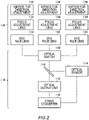
- FIG. 2 is a diagram schematically illustrating an example of a configuration of the backbone part 110 and the head part 130. Although a case in which three head parts 130 are provided is exemplified herein, the number of the head part 130 is not limited thereto, and there may be two head parts 130, or four or more head parts 130.
- the backbone part 110 has an optical output unit 112, an optical sensor 114, an Ether converter 116, an optical splitter 118, and an optical switch 120.
- the optical output unit 112 may be an example of the transmitting optical output unit.
- the Ether converter 116 converts an electrical signal of information to be transmitted into an optical signal, for example.
- the optical output unit 112 may output the optical signal converted with the Ether converter 116 to the optical switch 120 via the optical splitter 118.
- the optical output unit 112 may change the frequency of a light per communication partner.
- the control unit 102 may transmit information to each of the plurality of communication partners by, for example, controlling the optical output unit 112, the Ether converter 116, and the optical switch 120, thereby emitting the laser 140 from each of the plurality of head parts 130 by switching and guiding a light output by the optical output unit 112 to the plurality of head parts 130 with the optical switch 120.
- the optical sensor 114 may be an example of the receiving optical sensor.
- the control unit 102 performs control such that a light received by the plurality of head parts 130 is switched with the optical switch 120 and guided to the optical sensor 114.
- the optical sensor 114 outputs the received optical signal to the Ether converter 116, and the Ether converter 116 converts the received optical signal into information.
- the head part 130 has an end face lens 132, a focus adjustment lens 134, and a mirror for direction adjustment 136.
- the end face lens 132 may be arranged at one end of an optical fiber in which the other end is connected to the optical switch 120.
- a position of the focus adjustment lens 134 relative to the end face lens 132 is changeable, and the focus adjustment lens 134 adjusts a focus of a light emitted from the end face lens 132 and a light entering the end face lens 132.
- the mirror for direction adjustment 136 is arranged with respect to the end face lens 132 and the focus adjustment lens 134, and the mirror for direction adjustment 136 adjusts a direction of a light emitted from the end face lens 132 and the focus adjustment lens 134. In addition, the mirror for direction adjustment 136 adjusts a direction of a light from the outside with respect to the end face lens 132 and the focus adjustment lens 134.
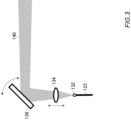
- FIG. 3 is an illustration for describing adjustment of the laser 140 by the head part 130.
- the end face lens 132 emits a light supplied from an optical fiber 122.
- the control unit 102 may adjust a focus by moving the focus adjustment lens 134 relative to the end face lens 132.
- the control unit 102 may control a direction of the laser 140 by adjusting an angle of the mirror for direction adjustment 136.
- the head part 130 may perform a total of three-axis control, which are two axes of direction control and one axis for focusing.
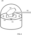
- FIG. 4 is a diagram schematically illustrating an example of the head part 130.
- FIG. 4 exemplifies the head part 130 having a dome shape.
- the control unit 102 adjusts the direction of the laser 140 emitted from the end face lens 132 and the focus adjustment lens 134 by the mirror for direction adjustment 136, and irradiates the laser 140 to a communication partner.
- the head part 130 may have an optical sensor 150 for measuring an intensity of a light from the outside.
- the optical sensor 150 may be an example of the measuring optical sensor.
- FIG. 4 exemplifies a case in which the head part 130 has three optical sensors 150, the number of the optical sensor 150 is not limited thereto. The number of the optical sensor 150 may be other numbers, but is desirably plural.
- the control unit 102 may, based on an intensity of a light from an optical communication device of a communication partner measured with the optical sensor 150, perform adjustment of an irradiation direction of the light by communicating with the optical communication device of the communication partner. For example, the control unit 102 may acquire a two-dimensional intensity information of the light (a peak position of the beam) from the communication partner based on a measurement result by a plurality of the optical sensors 150. The control unit 102 may perform the adjustment of the irradiation direction of the light by, for example, informing the optical communication device of the communication partner of a peak position of a light intensity of a receiving beam, and causing the optical communication device of the communication partner to correct the peak position so as to approach the position of the mirror for direction adjustment 136.
- the optical communication device 100 and the optical communication device of the communication partner may mutually perform adjustment of the irradiation direction of the light by informing each other. In this manner, the optical communication device 100 performs a beam direction correction in an ultra-short cycle.
- the control unit 102 may also adjust the mirror for direction adjustment 136 based on the intensity of the light from the optical communication device of the communication partner measured with the optical sensor 150.
- the optical communication device 100 may be mounted on a mobile object.
- the optical communication device 100 is mounted on, for example, a flying object.
- the optical communication device 100 may be mounted on a flying object having an antenna for providing a wireless communication service to a user terminal within a communication area that is formed by irradiating a beam to the ground.
- Fig. 5 is a diagram schematically illustrating an example of a HAPS 200.
- the HAPS 200 may be an example of a flying object having an antenna for providing a wireless communication service to 30 within a communication area 234 that is formed by irradiating a laser 232 to the ground.
- the HAPS 200 includes a fuselage 202, a central part 204, a propeller 206, a pod 208, and a solar panel 210.
- a control unit 220, a control unit 230, and the control unit 102 are arranged in the central part 204.
- An electrical power generated by the solar panel 210 is stored in one or more batteries arranged in at least any of the fuselage 202, the central part 204, and the pod 208.
- the electrical power stored in the battery is utilized by each configuration included in the HAPS 200.
- the control unit 220 controls a flight of the HAPS 200.
- the control unit 220 controls the flight of the HAPS 200 by, for example, controlling a rotation of the propeller 206.
- the control unit 220 may also control the flight of the HAPS 200 by changing an angle of a flap or an elevator, which are not illustrated.
- the control unit 220 may include various types of sensors such as a positioning sensor such as a Global Positioning System (GPS) sensor, a gyro sensor, and an acceleration sensor, and manage the position, moving direction, and moving speed of the HAPS 200.
- GPS Global Positioning System
- the control unit 230 controls communication of the HAPS 200 with the ground.
- the control unit 220 forms the communication area 234 on the ground by using a Service Link (SL) antenna.
- the control unit 230 forms a service link with the user terminal 30 on the ground by using the SL antenna.
- the SL antenna may also be a multi-beam antenna.
- the cell communication area 234 may also be multi-cell.
- the control unit 230 may form a feeder link with a gateway 40 on the ground by using a Feeder Link (FL) antenna.
- the control unit 230 may access a network 20 via the gateway 40.
- FL Feeder Link
- the control unit 230 may communicate with a communication satellite 50 by using a satellite communication antenna.
- the control unit 230 may access the network 20 via the communication satellite 50 and a satellite communication station 60.
- the user terminal 30 may be any communication terminal as long as it can communicate with the HAPS 200.
- the user terminal 30 is a mobile phone such as a smartphone.
- the user terminal 30 may also be a tablet terminal, a Personal Computer (PC), and the like.
- the user terminal 30 may also be a so-called Internet of Thing (IoT) device.
- the user terminal 30 can include all things corresponding to a so-called Internet of Everything (loE).
- the HAPS 200 relays communication between the network 20 and the user terminal 30 via, for example, the feeder link or the communication satellite 50 and the service link.
- the HAPS 200 may provide the user terminal 30 with a wireless communication service by relaying the communication between the user terminal 30 and the network 20.
- the network 20 includes a mobile object communication network.
- the mobile object communication network may comply with any of 3rd Generation (3G) communication scheme, Long Term Evolution (LTE) communication scheme, 5th Generation (5G) communication scheme, and a communication scheme after 6th Generation (6G) communication scheme.
- the network 20 may include the Internet.
- the HAPS 200 transmits data received from the user terminal 30 within the communication area 234 to the network 20.
- the HAPS 200 transmits the data to the user terminal 30.
- a management device 300 manages a plurality of the HAPSs 200.
- the management device 300 may communicate with the HAPS 200 via the network 20 and the gateway 40.
- the management device 300 may also communicate with the HAPS 200 via the network 20, the satellite communication station 60, and the communication satellite 50.
- the management device 300 controls the HAPS 200 by transmitting an instruction.
- the management device 300 may cause the HAPS 200 to swirl in the upper air of the target area.
- the HAPS 200 maintains the feeder link with the gateway 40 by adjusting an orientation direction of the FL antenna, and maintains the coverage of the target area with the communication area 234 by adjusting an orientation direction of the SL antenna, while flying in the upper air of the target area in a circular orbit.
- the backbone part 110 is arranged near the center of the optical communication device 100, and is connected to the head part 130 arranged in the pod 208 with the optical fiber 122 and a metal cable 124.
- the head part 130 arranged in the pod 208 with the optical fiber 122 and a metal cable 124.
- a case in which four head parts 130 are arranged in the HAPS 200 is described herein as an example.
- the control unit 102 retains three-dimensional structural information of the HAPS 200.
- the three-dimensional structural information includes information such as a structure of the fuselage 202 of the HAPS 200, and an installation position of the head part 130 in the fuselage 202.
- the control unit 102 may acquire spatial coordinates and an attitude angle of the HAPS 200 from the control unit 220, the control unit 230, and the like, and may constantly updates and maintains them.
- the control unit 102 may transmit its receiving sensor coordinates and receiving power information by giving these to a header part of a transmission frame to be transmitted by optical communication. At the time of receiving information by optical communication, the control unit 102 may read the receiving sensor coordinates and the receiving power information of the communication partner that are included in a header of a reception frame. Furthermore, the control unit 102 may perform control of the mirror for direction adjustment 136 such that a laser for communication reaches coordinates calculated from the information on the spatial coordinates, the attitude angle, and the like of the HAPS 200, and the receiving sensor coordinates and the receiving power information of the communication partner.
- FIG. 6 and FIG. 7 illustrate an example of an optical communication state between the HAPS 200 and other HAPSs 200.
- a HAPS 240 and a HAPS 250 are exemplified as the other HAPSs 200 herein.
- the HAPS 200 can maintain two links in any arrangement by having two head parts 130 in each of right and left.
- the link with the HAPS 240 and the link with the HAPS 250 can be maintained even if the HAPS 200 has one head part 130 in each of right and left.
- the fuselage of the HAPS 200 becomes a dead angle, and thus a link can be maintained with only either of the HAPS 240 and the HAPS 250 in the case of having one head part 130 in each of right and left.
- the 200 having two head parts 130 in each of right and left can maintain the link with the HAPS 240 and the link with the HAPS 250 even in the arrangement as exemplified in FIG. 7 .
- the number of the head part 130 to be required depends on a fuselage structure and the like of the HAPS 200. With the optical communication device 100 according to the present embodiment, even if the number of the head part 130 required becomes large, it is possible to deal with this by adding only the head part 130, and thus it can contribute to reduction of the weight and the cost of the HAPS 200.
- FIG. 8 is a diagram schematically illustrating an example of a flow of processing by the optical communication device 100. A flow of processing until the start of communication between the HAPS 200, and the HAPS 200 of a communication partner, will be described herein.
- optical communication between flying objects requires beam tracking of an extremely high accuracy because the flying objects are always moving. Since there are no beam intensity information and the like from a communication partner before linking up with the communication partner, it is difficult to target a reception unit of the communication partner. Spatial positioning of a high accuracy is difficult for an object in the air, and there are no coordinates/attitude acquisition methods other than the Global Positioning System (GPS)/ Inertial Measurement Unit (IMU).
- GPS Global Positioning System
- IMU Inertial Measurement Unit
- step (step may be abbreviated and described as S) 102 the control unit 102 shares position information with a communication partner.
- the control unit 102 acquires position information of the HAPS 200 from the control unit 220, and for example, transmits its own device information including the position information to the communication partner via the communication satellite 50, while also receiving communication partner information including position information of the communication partner from the communication partner via the communication satellite 50.
- the control unit 102 may transmit its own device information to the management device 300 via the communication satellite 50, and may receive the communication partner information from the management device 300 via the communication satellite 50. If communication with the communication partner using electric waves can be performed, the control unit 102 may communicate its own device information and the communication partner information through communication with the electric waves.
- the control unit 102 controls the backbone part 110 and the head part 130, and irradiates a beam of a first beam width to a position specified by the position information of the communication partner.
- the first beam width may be, for example, a width greater than a GPS positioning error.
- a beam irradiated by the communication partner is received.
- control unit 102 determines whether a received-light intensity of the beam from the communication partner measured with the optical sensor 150 is stronger than a predetermined threshold value. If it is determined to be weaker than the threshold value, the processing proceeds to S110 to adjust the mirror for direction adjustment 136, and returns to S108. If it is determined to be stronger than the threshold value, the processing proceeds to S112.
- the control unit 102 controls the head part 130 such that the beam width is changed from the first width to a second width narrower than the first width.
- the control unit 102 refers to the received-light intensity measured with the optical sensor 150, and performs adjustment while reducing the beam width in a stepwise manner.
- the control unit 102 may change the beam width to the second width by adjusting the beam width and the orientation of the mirror for direction adjustment 136 so that the received-light intensity is maximized.
- optical communication with the communication partner starts after the completion of the adjustment.
- the embodiment is not limited thereto.
- the optical communication device 100 may be able to, among transmission and reception by optical communication, perform only transmission or perform only reception.
- the optical communication device 100 may include the optical output unit 112, the optical switch 120 connected to the optical output unit 112, the plurality of head parts 130 connected to the optical switch 120, and the control unit 102 for performing control so as to transmit information by emitting a laser from each of the plurality of head parts 130 by switching and guiding a light output by the optical output unit 112 to the plurality of head parts 130 with the optical switch 120.
- the optical communication device 100 may include the optical sensor 114, the optical switch 120 connected the optical sensor 114, the plurality of head parts 130 connected to the optical switch 120, and the control unit 102 for performing control so as to receive information by switching a light received by the plurality of head parts 130 with the optical switch 120 and guiding the light to the optical sensor 114.
- FIG. 9 is a diagram schematically illustrating an example of a hardware configuration of a computer 1200 functioning as the optical communication device 100.
- Programs installed in the computer 1200 can cause the computer 1200 to function as one or more "units" of the device according to the above-described embodiment or can cause the computer 1200 to execute operations associated with the devices according to the above-described embodiment or the one or more "units", and/or can cause the computer 1200 to execute a process according to the above-described embodiment or steps of the process.
- Such a program may be executed by a CPU 1212 to cause the computer 1200 to perform specific operations associated with some or all of the blocks in the flow charts and block diagrams described in the specification.
- the computer 1200 includes the CPU 1212, a RAM 1214, and a graphics controller 1216, which are connected to each other via a host controller 1210. Also, the computer 1200 includes input/output units such as a communication interface 1222, a storage device 1224, a DVD drive and an IC card drive, which are connected to the host controller 1210 via an input/output controller 1220.
- the storage device 1224 may be a hard disk drive, a solid-state drive, and the like.
- the computer 1200 also includes a ROM 1230 and a legacy input/output unit such as a keyboard, which are connected to the input/output controller 1220 via an input/output chip 1240.
- the CPU 1212 operates according to the programs stored in the ROM 1230 and the RAM 1214, thereby controlling each unit.
- the graphics controller 1216 obtains image data which is generated, by the CPU 1212, in a frame buffer or the like provided in the RAM 1214 or in itself so as to cause the image data to be displayed on a display device 1218.
- the communication interface 1222 communicates with other electronic devices via a network.
- the storage device 1224 stores a program and data used by the CPU 1212 in the computer 1200.
- the IC card drive reads the program and data from the IC card, and/or writes the program and data to the IC card.
- the ROM 1230 stores therein a boot program or the like executed by the computer 1200 at the time of activation, and/or a program depending on the hardware of the computer 1200.
- the input/output chip 1240 may also connect various input/output units via a USB port, a parallel port, a serial port, a keyboard port, a mouse port or the like to the input/output controller 1220.
- a program is provided by a computer-readable storage medium such as the DVD-ROM or the IC card.
- the program is read from the computer-readable storage medium, installed into the storage device 1224, RAM 1214, or ROM 1230, which are also examples of a computer-readable storage medium, and executed by the CPU 1212.
- Information processing written in these programs is read by the computer 1200, and provides cooperation between the programs and the various types of hardware resources described above.
- a device or method may be constituted by realizing the operation or processing of information in accordance with the usage of the computer 1200.
- the CPU 1212 may execute a communication program loaded in the RAM 1214 and instruct the communication interface 1222 to perform communication processing based on a processing written in the communication program.
- the communication interface 1222 under control of the CPU 1212, reads transmission data stored on a transmission buffer region provided in a recording medium such as the RAM 1214, the storage device 1224, the DVD-ROM, or the IC card, and transmits the read transmission data to a network or writes reception data received from a network to a reception buffer region or the like provided on the recording medium.
- the CPU 1212 may cause all or a necessary portion of a file or a database to be read into the RAM 1214, the file or the database having been stored in an external recording medium such as the storage device 1224, the DVD drive (DVD-ROM), the IC card, etc., and perform various types of processing on the data on the RAM 1214. Then, the CPU 1212 may write the processed data back in the external recording medium.
- an external recording medium such as the storage device 1224, the DVD drive (DVD-ROM), the IC card, etc.
- the CPU 1212 may execute, on the data read from the RAM 1214, various types of processings including various types of operations, information processing, conditional judgement, conditional branching, unconditional branching, information retrieval/replacement, or the like described throughout the present disclosure and specified by instruction sequences of the programs, and writes the results back to the RAM 1214.
- the CPU 1212 may retrieve information in a file, a database, or the like in the recording medium.
- the CPU 1212 may search for an entry whose attribute value of the first attribute matches a designated condition, from among the plurality of entries, and read the attribute value of the second attribute stored in the entry, thereby obtaining the attribute value of the second attribute associated with the first attribute satisfying the predetermined condition.
- the programs or software module described above may be stored on the computer 1200 or in a computer-readable storage medium near the computer 1200.
- a recording medium such as a hard disk or a RAM provided in a server system connected to a dedicated communication network or the Internet can be used as the computer-readable storage medium, thereby providing the program to the computer 1200 via the network.
- Blocks in flow charts and block diagrams in the present embodiments may represent steps of processes in which operations are performed or "units" of devices responsible for performing operations.
- a specific step and "unit” may be implemented by a dedicated circuit, a programmable circuit supplied along with a computer-readable instruction stored on a computer-readable storage medium, and/or a processor supplied along with the computer-readable instruction stored on the computer-readable storage medium.
- the dedicated circuit may include a digital and/or analog hardware circuit, or may include an integrated circuit (IC) and/or a discrete circuit.
- the programmable circuit may include, for example, a reconfigurable hardware circuit including logical AND, logical OR, logical XOR, logical NAND, logical NOR, and other logical operations, and a flip-flop, a register, and a memory element, such as a field programmable gate array (FPGA) and a programmable logic array (PLA).
- a reconfigurable hardware circuit including logical AND, logical OR, logical XOR, logical NAND, logical NOR, and other logical operations, and a flip-flop, a register, and a memory element, such as a field programmable gate array (FPGA) and a programmable logic array (PLA).
- FPGA field programmable gate array
- PLA programmable logic array
- the computer-readable storage medium may include any tangible device capable of storing an instruction performed by an appropriate device, so that the computer-readable storage medium having the instruction stored thereon constitutes a product including an instruction that may be performed in order to provide means to perform an operation specified by a flowchart or a block diagram.
- Examples of the computer-readable storage medium may include an electronic storage medium, a magnetic storage medium, an optical storage medium, an electromagnetic storage medium, a semiconductor storage medium, or the like.
- Computer-readable storage media may include a floppy (registered trademark) disk, a diskette, a hard disk, a random access memory (RAM), a read-only memory (ROM), an erasable programmable read-only memory (EPROM or Flash memory), an electrically erasable programmable read-only memory (EEPROM), a static random access memory (SRAM), a compact disc read-only memory (CD-ROM), a digital versatile disk (DVD), a BLU-RAY(registered trademark) disc, a memory stick, an integrated circuit card, etc.
- a floppy (registered trademark) disk a diskette, a hard disk, a random access memory (RAM), a read-only memory (ROM), an erasable programmable read-only memory (EPROM or Flash memory), an electrically erasable programmable read-only memory (EEPROM), a static random access memory (SRAM), a compact disc read-only memory (CD-ROM), a digital versatile disk (DVD),
- the computer-readable instruction may include either of source code or object code written in any combination of one or more programming languages including: an assembler instruction, an instruction-set-architecture (ISA) instruction, a machine instruction, a machine dependent instruction, a microcode, a firmware instruction, state-setting data; or an object oriented programming language such as Smalltalk (registered trademark), JAVA (registered trademark), C++, or the like; and a conventional procedural programming language such as a "C" programming language or a similar programming language.
- ISA instruction-set-architecture
- machine instruction a machine dependent instruction
- microcode a firmware instruction
- state-setting data state-setting data
- object oriented programming language such as Smalltalk (registered trademark), JAVA (registered trademark), C++, or the like
- a conventional procedural programming language such as a "C" programming language or a similar programming language.
- the computer-readable instruction may be provided to a general-purpose computer, a special purpose computer, or a processor or a programmable circuit of another programmable data processing device locally or via a local area network (LAN), a wide area network (WAN) such as the Internet or the like in order that the general-purpose computer, the special purpose computer, or the processor or the programmable circuit of another programmable data processing device is to perform the computer-readable instruction to provide means to perform operations specified by the flowchart or the block diagram.
- the processor include a computer processor, a processing unit, a microprocessor, a digital signal processor, a controller, a microcontroller, and the like.
- 20 network, 30: user terminal, 40: gateway, 50: communication satellite, 60: satellite communication station, 100: optical communication device, 102: control unit, 110: backbone part, 112: optical output unit, 114: optical sensor, 116: Ether converter, 118: optical splitter, 120: optical switch, 122: optical fiber, 124: metal cable, 130: head part, 132: end face lens, 134: focus adjustment lens, 136: mirror for direction adjustment, 140: laser, 150: optical sensor, 200: HAPS, 202: fuselage, 204: central part, 206: propeller, 208: pod, 210: solar panel, 220: control unit, 230: control unit, 232: laser, 234: communication area, 240: HAPS, 250: HAPS, 300: management device, 1200: computer, 1210: host controller, 1212: CPU, 1214: RAM, 1216: graphics controller, 1218: display device, 1220: input/output controller, 1222: communication interface, 1224: storage device, 1230: ROM,
Landscapes
- Physics & Mathematics (AREA)
- Engineering & Computer Science (AREA)
- Computer Networks & Wireless Communication (AREA)
- Electromagnetism (AREA)
- Signal Processing (AREA)
- General Physics & Mathematics (AREA)
- Optics & Photonics (AREA)
- Astronomy & Astrophysics (AREA)
- Optical Communication System (AREA)
- Mechanical Light Control Or Optical Switches (AREA)
Abstract
Description
- The present invention relates to an optical communication device, a program, a system, and an optical communication method.
- An optical communication technique for communicating with a communication partner by using a laser light has been known (for example, see Patent document 1).
- Patent document 1:
Japanese Patent Application Publication No. 2020-010219 - According to a first aspect of the present invention, an optical communication device is provided. The optical communication device may include a transmitting optical output unit for transmitting information by optical communication. The optical communication device may include a receiving optical sensor for receiving information by optical communication. The optical communication device may include an optical switch that is connected to the transmitting optical output unit and the receiving optical sensor via an optical splitter. The optical communication device may include a plurality of head parts that are connected to the optical switch. The optical communication device may include a control unit for performing control so as to transmit information by emitting a laser from each of the plurality of head parts by switching and guiding a light output by the transmitting optical output unit to the plurality of head parts with the optical switch, and receive information by switching a light received by the plurality of head parts with the optical switch and guiding the light to the receiving optical sensor.
- Each of the above-described plurality of head parts may have a lens part including an end face lens that is arranged at one end of an optical fiber in which the other end is connected to the above-described optical switch, and a focusing lens for adjusting a focus. Each of the above-described plurality of head parts may have a mirror for direction adjustment that is arranged with respect to the above-described lens part, for adjusting a direction of a light emitted from the above-described lens part and adjusting a direction of a light from the outside with respect to the above-described lens part. Each of the above-described plurality of head parts may have a measuring optical sensor for measuring an intensity of the light from the outside. The above-described control unit may, based on an intensity of a light from an optical communication device of a communication partner that is measured with the above-described measuring optical sensor, communicate with the above-described optical communication device of the communication partner, and perform adjustment of an irradiation direction of the light. The above-described control unit may acquire a two-dimensional intensity information of the light from the communication partner based on a measurement result by a plurality of the above-described measuring optical sensors. The above-described control unit may perform adjustment of the irradiation direction of the light by informing the optical communication device of the communication partner of a peak position of a light intensity of a receiving beam, and causing the optical communication device of the communication partner to correct the peak position so as to approach the position of the mirror for direction adjustment. Each of the above-described plurality of head parts may have the mirror for direction adjustment that is arranged with respect to the above-described lens part, for adjusting a direction of a light emitted from the above-described lens part and adjusting a direction of a light from the outside with respect to the above-described lens part, and the measuring optical sensor for measuring an intensity of the light from the outside. The above-described control unit may adjust the above-described mirror for direction adjustment based on the intensity of the light from the optical communication device of the communication partner that is measured with the above-described measuring optical sensor.
- The above-described optical communication device may be mounted on a mobile object. The above-described optical communication device may be mounted on a flying object. The above-described optical communication device may be mounted on a flying object having an antenna for providing a wireless communication service to a user terminal within a communication area that is formed by irradiating a beam to the ground. The above-described control unit may acquire communication partner information including position information of a flying object of a communication partner, and control the above-described head part such that a beam of a first width is emitted from at least any head part of the above-described plurality of head parts to a position represented by the above-described position information, and in response to receiving information of the above-described flying object of the communication partner by receiving a light from the above-described flying object of the communication partner, the width of the beam of the above-described head part is changed from the above-described first width to a second width that is narrower than the above-described first width.
- According to a second aspect of the present invention, a program for causing a computer to function as the above-described optical communication device is provided.
- According to a third aspect of the present invention, a system including the above-described optical communication device and the above-described mobile object on which the above-described optical communication device is mounted, is provided.
- According to a fourth aspect of the present invention, an optical communication device is provided. The optical communication device may include an optical output unit. The optical communication device may include an optical switch that is connected to the optical output unit. The optical communication device may include a plurality of head parts that are connected to the optical switch. The optical communication device may include a control unit for performing control so as to transmit information by emitting a laser from each of the plurality of head parts by switching and guiding a light output by the optical output unit to the plurality of head parts with the optical switch.
- According to a fourth aspect of the present invention, an optical communication device is provided. The optical communication device may include an optical sensor. The optical communication device may include an optical switch that is connected to the optical sensor. The optical communication device may include a plurality of head parts that are connected to the optical switch. The optical communication device may include a control unit for performing control so as to receive information by switching a light received by the plurality of head parts with the optical switch and guiding the light to the optical sensor.
- The above-described summary of the invention does not necessarily describe all necessary features of the embodiments of the present invention. In addition, the present invention may also be a sub-combination of the features described above.
-
-
FIG. 1 is a diagram schematically illustrating an example of a functional configuration of anoptical communication device 100. -
FIG. 2 is a diagram schematically illustrating an example of a configuration of abackbone part 110 and ahead part 130. -
FIG. 3 is an illustration for describing adjustment of alaser 140 by thehead part 130. -
FIG. 4 is a diagram schematically illustrating an example of thehead part 130. -
FIG. 5 is a diagram schematically illustrating an example of aHAPS 200. -
FIG. 6 illustrates an example of an optical communication state between theHAPS 200 andother HAPSs 200. -
FIG. 7 illustrates an example of the optical communication state between theHAPS 200 and theother HAPSs 200. -
FIG. 8 is a diagram schematically illustrating an example of a flow of processing by theoptical communication device 100. -
FIG. 9 is a diagram schematically illustrating an example of a hardware configuration of acomputer 1200 functioning as anoptical communication device 200. - Hereinafter, the present invention will be described through embodiments of the invention, but the following embodiments do not limit the invention according to claims. In addition, not all of the combinations of features described in the embodiments are essential to the solving means of the invention.
-
FIG. 1 is a diagram schematically illustrating an example of a functional configuration of anoptical communication device 100. Theoptical communication device 100 includes acontrol unit 102, abackbone part 110, and a plurality ofhead parts 130. - The
control unit 102 controls thebackbone part 110 and the plurality ofhead parts 130. Thecontrol unit 102 and thebackbone part 110 may be connected by a metal cable or the like. Thebackbone part 110 and each of the plurality ofhead parts 130 may be connected by an optical fiber for communication and a metal cable for control. Thecontrol unit 102 may control the plurality ofhead parts 130 via thebackbone part 110. It should be noted that thecontrol unit 102 and each of the plurality ofhead parts 130 may be directly connected, and thecontrol unit 102 may control the plurality ofhead parts 130 via that connection. - The
backbone part 110 may have a transmitting optical output unit for transmitting information by optical communication, a receiving optical sensor for receiving information by optical communication, and an optical switch that is connected to the transmitting optical output unit and the receiving optical sensor via an optical splitter. The plurality ofhead parts 130 may be connected to the optical switch. Each of the plurality ofhead parts 130 may have a lens part and a mirror for direction adjustment that is arranged with respect to the lens part, for adjusting a direction of a light emitted from the lens part and adjusting a direction of a light from the outside with respect to the lens part. - The
control unit 102 may perform control so as to transmit information by emitting alaser 140 from each of the plurality ofhead parts 130 by switching and guiding a light output by the transmitting optical output unit to the plurality ofhead parts 130 with the optical switch. Thecontrol unit 102 may perform control so as to receive information by switching the light received by the plurality ofhead parts 130 with the optical switch and guiding the light to the receiving optical sensor. - Conventionally, if a plurality of optical wireless transmission/reception units are to be included in an optical communication device, there is a need to include a plurality of sets of an optical output unit, an optical sensor, and a head part. In contrast, the
optical communication device 100 according to the present embodiment allows the plurality ofhead parts 130 to share one transmitting optical output unit and one receiving optical sensor by using a configuration of switching a light to the plurality ofhead parts 130 and a light from the plurality ofhead parts 130 with the optical switch. In this manner, the plurality of optical wireless transmission/reception units can be included with one optical output unit and one optical sensor, and it is possible to reduce the entire weight or reduce the cost of the optical wireless device. -
FIG. 2 is a diagram schematically illustrating an example of a configuration of thebackbone part 110 and thehead part 130. Although a case in which threehead parts 130 are provided is exemplified herein, the number of thehead part 130 is not limited thereto, and there may be twohead parts 130, or four ormore head parts 130. - The
backbone part 110 has anoptical output unit 112, anoptical sensor 114, anEther converter 116, anoptical splitter 118, and anoptical switch 120. Theoptical output unit 112 may be an example of the transmitting optical output unit. TheEther converter 116 converts an electrical signal of information to be transmitted into an optical signal, for example. Theoptical output unit 112 may output the optical signal converted with theEther converter 116 to theoptical switch 120 via theoptical splitter 118. When communicating with a plurality of communication partners, theoptical output unit 112 may change the frequency of a light per communication partner. - The
control unit 102 may transmit information to each of the plurality of communication partners by, for example, controlling theoptical output unit 112, theEther converter 116, and theoptical switch 120, thereby emitting thelaser 140 from each of the plurality ofhead parts 130 by switching and guiding a light output by theoptical output unit 112 to the plurality ofhead parts 130 with theoptical switch 120. - The
optical sensor 114 may be an example of the receiving optical sensor. Thecontrol unit 102 performs control such that a light received by the plurality ofhead parts 130 is switched with theoptical switch 120 and guided to theoptical sensor 114. Theoptical sensor 114 outputs the received optical signal to theEther converter 116, and theEther converter 116 converts the received optical signal into information. - The
head part 130 has anend face lens 132, afocus adjustment lens 134, and a mirror fordirection adjustment 136. Theend face lens 132 may be arranged at one end of an optical fiber in which the other end is connected to theoptical switch 120. A position of thefocus adjustment lens 134 relative to theend face lens 132 is changeable, and thefocus adjustment lens 134 adjusts a focus of a light emitted from theend face lens 132 and a light entering theend face lens 132. - The mirror for
direction adjustment 136 is arranged with respect to theend face lens 132 and thefocus adjustment lens 134, and the mirror fordirection adjustment 136 adjusts a direction of a light emitted from theend face lens 132 and thefocus adjustment lens 134. In addition, the mirror fordirection adjustment 136 adjusts a direction of a light from the outside with respect to theend face lens 132 and thefocus adjustment lens 134. -
FIG. 3 is an illustration for describing adjustment of thelaser 140 by thehead part 130. Theend face lens 132 emits a light supplied from anoptical fiber 122. Thecontrol unit 102 may adjust a focus by moving thefocus adjustment lens 134 relative to theend face lens 132. Thecontrol unit 102 may control a direction of thelaser 140 by adjusting an angle of the mirror fordirection adjustment 136. In this manner, thehead part 130 may perform a total of three-axis control, which are two axes of direction control and one axis for focusing. -
FIG. 4 is a diagram schematically illustrating an example of thehead part 130.FIG. 4 exemplifies thehead part 130 having a dome shape. Thecontrol unit 102 adjusts the direction of thelaser 140 emitted from theend face lens 132 and thefocus adjustment lens 134 by the mirror fordirection adjustment 136, and irradiates thelaser 140 to a communication partner. - The
head part 130 may have anoptical sensor 150 for measuring an intensity of a light from the outside. Theoptical sensor 150 may be an example of the measuring optical sensor. AlthoughFIG. 4 exemplifies a case in which thehead part 130 has threeoptical sensors 150, the number of theoptical sensor 150 is not limited thereto. The number of theoptical sensor 150 may be other numbers, but is desirably plural. - The
control unit 102 may, based on an intensity of a light from an optical communication device of a communication partner measured with theoptical sensor 150, perform adjustment of an irradiation direction of the light by communicating with the optical communication device of the communication partner. For example, thecontrol unit 102 may acquire a two-dimensional intensity information of the light (a peak position of the beam) from the communication partner based on a measurement result by a plurality of theoptical sensors 150. Thecontrol unit 102 may perform the adjustment of the irradiation direction of the light by, for example, informing the optical communication device of the communication partner of a peak position of a light intensity of a receiving beam, and causing the optical communication device of the communication partner to correct the peak position so as to approach the position of the mirror fordirection adjustment 136. Theoptical communication device 100 and the optical communication device of the communication partner may mutually perform adjustment of the irradiation direction of the light by informing each other. In this manner, theoptical communication device 100 performs a beam direction correction in an ultra-short cycle. Thecontrol unit 102 may also adjust the mirror fordirection adjustment 136 based on the intensity of the light from the optical communication device of the communication partner measured with theoptical sensor 150. - The
optical communication device 100 may be mounted on a mobile object. Theoptical communication device 100 is mounted on, for example, a flying object. Theoptical communication device 100 may be mounted on a flying object having an antenna for providing a wireless communication service to a user terminal within a communication area that is formed by irradiating a beam to the ground. -
Fig. 5 is a diagram schematically illustrating an example of aHAPS 200. TheHAPS 200 may be an example of a flying object having an antenna for providing a wireless communication service to 30 within acommunication area 234 that is formed by irradiating alaser 232 to the ground. - The
HAPS 200 includes afuselage 202, acentral part 204, apropeller 206, apod 208, and asolar panel 210. Acontrol unit 220, acontrol unit 230, and thecontrol unit 102 are arranged in thecentral part 204. - An electrical power generated by the
solar panel 210 is stored in one or more batteries arranged in at least any of thefuselage 202, thecentral part 204, and thepod 208. The electrical power stored in the battery is utilized by each configuration included in theHAPS 200. - The
control unit 220 controls a flight of theHAPS 200. Thecontrol unit 220 controls the flight of theHAPS 200 by, for example, controlling a rotation of thepropeller 206. In addition, thecontrol unit 220 may also control the flight of theHAPS 200 by changing an angle of a flap or an elevator, which are not illustrated. Thecontrol unit 220 may include various types of sensors such as a positioning sensor such as a Global Positioning System (GPS) sensor, a gyro sensor, and an acceleration sensor, and manage the position, moving direction, and moving speed of theHAPS 200. - The
control unit 230 controls communication of theHAPS 200 with the ground. Thecontrol unit 220 forms thecommunication area 234 on the ground by using a Service Link (SL) antenna. Thecontrol unit 230 forms a service link with theuser terminal 30 on the ground by using the SL antenna. The SL antenna may also be a multi-beam antenna. Thecell communication area 234 may also be multi-cell. - The
control unit 230 may form a feeder link with agateway 40 on the ground by using a Feeder Link (FL) antenna. Thecontrol unit 230 may access anetwork 20 via thegateway 40. - The
control unit 230 may communicate with acommunication satellite 50 by using a satellite communication antenna. - The
control unit 230 may access thenetwork 20 via thecommunication satellite 50 and asatellite communication station 60. - The
user terminal 30 may be any communication terminal as long as it can communicate with theHAPS 200. For example, theuser terminal 30 is a mobile phone such as a smartphone. Theuser terminal 30 may also be a tablet terminal, a Personal Computer (PC), and the like. Theuser terminal 30 may also be a so-called Internet of Thing (IoT) device. Theuser terminal 30 can include all things corresponding to a so-called Internet of Everything (loE). - The
HAPS 200 relays communication between thenetwork 20 and theuser terminal 30 via, for example, the feeder link or thecommunication satellite 50 and the service link. TheHAPS 200 may provide theuser terminal 30 with a wireless communication service by relaying the communication between theuser terminal 30 and thenetwork 20. - The
network 20 includes a mobile object communication network. The mobile object communication network may comply with any of 3rd Generation (3G) communication scheme, Long Term Evolution (LTE) communication scheme, 5th Generation (5G) communication scheme, and a communication scheme after 6th Generation (6G) communication scheme. Thenetwork 20 may include the Internet. - For example, the
HAPS 200 transmits data received from theuser terminal 30 within thecommunication area 234 to thenetwork 20. In addition, for example, when receiving data for theuser terminal 30 within thecommunication area 234 via thenetwork 20, theHAPS 200 transmits the data to theuser terminal 30. - A
management device 300 manages a plurality of theHAPSs 200. Themanagement device 300 may communicate with theHAPS 200 via thenetwork 20 and thegateway 40. Themanagement device 300 may also communicate with theHAPS 200 via thenetwork 20, thesatellite communication station 60, and thecommunication satellite 50. - The
management device 300 controls theHAPS 200 by transmitting an instruction. In order to cover a target area on the ground with thecommunication area 234, themanagement device 300 may cause theHAPS 200 to swirl in the upper air of the target area. For example, theHAPS 200 maintains the feeder link with thegateway 40 by adjusting an orientation direction of the FL antenna, and maintains the coverage of the target area with thecommunication area 234 by adjusting an orientation direction of the SL antenna, while flying in the upper air of the target area in a circular orbit. - In the example illustrated in
FIG. 5 , thebackbone part 110 is arranged near the center of theoptical communication device 100, and is connected to thehead part 130 arranged in thepod 208 with theoptical fiber 122 and ametal cable 124. A case in which fourhead parts 130 are arranged in theHAPS 200 is described herein as an example. - The
control unit 102 retains three-dimensional structural information of theHAPS 200. The three-dimensional structural information includes information such as a structure of thefuselage 202 of theHAPS 200, and an installation position of thehead part 130 in thefuselage 202. Thecontrol unit 102 may acquire spatial coordinates and an attitude angle of theHAPS 200 from thecontrol unit 220, thecontrol unit 230, and the like, and may constantly updates and maintains them. - The
control unit 102 may transmit its receiving sensor coordinates and receiving power information by giving these to a header part of a transmission frame to be transmitted by optical communication. At the time of receiving information by optical communication, thecontrol unit 102 may read the receiving sensor coordinates and the receiving power information of the communication partner that are included in a header of a reception frame. Furthermore, thecontrol unit 102 may perform control of the mirror fordirection adjustment 136 such that a laser for communication reaches coordinates calculated from the information on the spatial coordinates, the attitude angle, and the like of theHAPS 200, and the receiving sensor coordinates and the receiving power information of the communication partner. -
FIG. 6 andFIG. 7 illustrate an example of an optical communication state between theHAPS 200 andother HAPSs 200. AHAPS 240 and aHAPS 250 are exemplified as theother HAPSs 200 herein. TheHAPS 200 can maintain two links in any arrangement by having twohead parts 130 in each of right and left. - For example, in an arrangement as exemplified in
FIG. 6 , the link with theHAPS 240 and the link with theHAPS 250 can be maintained even if theHAPS 200 has onehead part 130 in each of right and left. However, in an arrangement as exemplified inFIG. 7 , the fuselage of theHAPS 200 becomes a dead angle, and thus a link can be maintained with only either of theHAPS 240 and theHAPS 250 in the case of having onehead part 130 in each of right and left. - In contrast, the 200 having two
head parts 130 in each of right and left can maintain the link with theHAPS 240 and the link with theHAPS 250 even in the arrangement as exemplified inFIG. 7 . The number of thehead part 130 to be required depends on a fuselage structure and the like of theHAPS 200. With theoptical communication device 100 according to the present embodiment, even if the number of thehead part 130 required becomes large, it is possible to deal with this by adding only thehead part 130, and thus it can contribute to reduction of the weight and the cost of theHAPS 200. -
FIG. 8 is a diagram schematically illustrating an example of a flow of processing by theoptical communication device 100. A flow of processing until the start of communication between theHAPS 200, and theHAPS 200 of a communication partner, will be described herein. - In particular, optical communication between flying objects such as HAPSs requires beam tracking of an extremely high accuracy because the flying objects are always moving. Since there are no beam intensity information and the like from a communication partner before linking up with the communication partner, it is difficult to target a reception unit of the communication partner. Spatial positioning of a high accuracy is difficult for an object in the air, and there are no coordinates/attitude acquisition methods other than the Global Positioning System (GPS)/ Inertial Measurement Unit (IMU). The
HAPS 200 according to the present embodiment may perform processing until the start of communication as follows. - In step (step may be abbreviated and described as S) 102, the
control unit 102 shares position information with a communication partner. Thecontrol unit 102 acquires position information of theHAPS 200 from thecontrol unit 220, and for example, transmits its own device information including the position information to the communication partner via thecommunication satellite 50, while also receiving communication partner information including position information of the communication partner from the communication partner via thecommunication satellite 50. - The
control unit 102 may transmit its own device information to themanagement device 300 via thecommunication satellite 50, and may receive the communication partner information from themanagement device 300 via thecommunication satellite 50. If communication with the communication partner using electric waves can be performed, thecontrol unit 102 may communicate its own device information and the communication partner information through communication with the electric waves. - In S104, the
control unit 102 controls thebackbone part 110 and thehead part 130, and irradiates a beam of a first beam width to a position specified by the position information of the communication partner. The first beam width may be, for example, a width greater than a GPS positioning error. In S106, a beam irradiated by the communication partner is received. - In S108, the
control unit 102 determines whether a received-light intensity of the beam from the communication partner measured with theoptical sensor 150 is stronger than a predetermined threshold value. If it is determined to be weaker than the threshold value, the processing proceeds to S110 to adjust the mirror fordirection adjustment 136, and returns to S108. If it is determined to be stronger than the threshold value, the processing proceeds to S112. - In S112, the
control unit 102 controls thehead part 130 such that the beam width is changed from the first width to a second width narrower than the first width. Thecontrol unit 102 refers to the received-light intensity measured with theoptical sensor 150, and performs adjustment while reducing the beam width in a stepwise manner. Thecontrol unit 102 may change the beam width to the second width by adjusting the beam width and the orientation of the mirror fordirection adjustment 136 so that the received-light intensity is maximized. In S114, optical communication with the communication partner starts after the completion of the adjustment. - Although the above-described embodiment described the example in which the
optical communication device 100 can perform transmission and reception by optical communication, the embodiment is not limited thereto. Theoptical communication device 100 may be able to, among transmission and reception by optical communication, perform only transmission or perform only reception. In the case of the former, theoptical communication device 100 may include theoptical output unit 112, theoptical switch 120 connected to theoptical output unit 112, the plurality ofhead parts 130 connected to theoptical switch 120, and thecontrol unit 102 for performing control so as to transmit information by emitting a laser from each of the plurality ofhead parts 130 by switching and guiding a light output by theoptical output unit 112 to the plurality ofhead parts 130 with theoptical switch 120. In the case of the latter, theoptical communication device 100 may include theoptical sensor 114, theoptical switch 120 connected theoptical sensor 114, the plurality ofhead parts 130 connected to theoptical switch 120, and thecontrol unit 102 for performing control so as to receive information by switching a light received by the plurality ofhead parts 130 with theoptical switch 120 and guiding the light to theoptical sensor 114. -
FIG. 9 is a diagram schematically illustrating an example of a hardware configuration of acomputer 1200 functioning as theoptical communication device 100. Programs installed in thecomputer 1200 can cause thecomputer 1200 to function as one or more "units" of the device according to the above-described embodiment or can cause thecomputer 1200 to execute operations associated with the devices according to the above-described embodiment or the one or more "units", and/or can cause thecomputer 1200 to execute a process according to the above-described embodiment or steps of the process. Such a program may be executed by aCPU 1212 to cause thecomputer 1200 to perform specific operations associated with some or all of the blocks in the flow charts and block diagrams described in the specification. - The
computer 1200 according to the present embodiment includes theCPU 1212, aRAM 1214, and agraphics controller 1216, which are connected to each other via ahost controller 1210. Also, thecomputer 1200 includes input/output units such as acommunication interface 1222, astorage device 1224, a DVD drive and an IC card drive, which are connected to thehost controller 1210 via an input/output controller 1220. Thestorage device 1224 may be a hard disk drive, a solid-state drive, and the like. Thecomputer 1200 also includes aROM 1230 and a legacy input/output unit such as a keyboard, which are connected to the input/output controller 1220 via an input/output chip 1240. - The
CPU 1212 operates according to the programs stored in theROM 1230 and theRAM 1214, thereby controlling each unit. Thegraphics controller 1216 obtains image data which is generated, by theCPU 1212, in a frame buffer or the like provided in theRAM 1214 or in itself so as to cause the image data to be displayed on adisplay device 1218. - The
communication interface 1222 communicates with other electronic devices via a network. Thestorage device 1224 stores a program and data used by theCPU 1212 in thecomputer 1200. The IC card drive reads the program and data from the IC card, and/or writes the program and data to the IC card. - The
ROM 1230 stores therein a boot program or the like executed by thecomputer 1200 at the time of activation, and/or a program depending on the hardware of thecomputer 1200. The input/output chip 1240 may also connect various input/output units via a USB port, a parallel port, a serial port, a keyboard port, a mouse port or the like to the input/output controller 1220. - A program is provided by a computer-readable storage medium such as the DVD-ROM or the IC card. The program is read from the computer-readable storage medium, installed into the
storage device 1224,RAM 1214, orROM 1230, which are also examples of a computer-readable storage medium, and executed by theCPU 1212. Information processing written in these programs is read by thecomputer 1200, and provides cooperation between the programs and the various types of hardware resources described above. A device or method may be constituted by realizing the operation or processing of information in accordance with the usage of thecomputer 1200. - For example, in a case where communication is performed between the
computer 1200 and an external device, theCPU 1212 may execute a communication program loaded in theRAM 1214 and instruct thecommunication interface 1222 to perform communication processing based on a processing written in the communication program. Thecommunication interface 1222, under control of theCPU 1212, reads transmission data stored on a transmission buffer region provided in a recording medium such as theRAM 1214, thestorage device 1224, the DVD-ROM, or the IC card, and transmits the read transmission data to a network or writes reception data received from a network to a reception buffer region or the like provided on the recording medium. - In addition, the
CPU 1212 may cause all or a necessary portion of a file or a database to be read into theRAM 1214, the file or the database having been stored in an external recording medium such as thestorage device 1224, the DVD drive (DVD-ROM), the IC card, etc., and perform various types of processing on the data on theRAM 1214. Then, theCPU 1212 may write the processed data back in the external recording medium. - Various types of programs, data, tables, and various types of information such as a database may be stored in a recording medium to receive information processing. The
CPU 1212 may execute, on the data read from theRAM 1214, various types of processings including various types of operations, information processing, conditional judgement, conditional branching, unconditional branching, information retrieval/replacement, or the like described throughout the present disclosure and specified by instruction sequences of the programs, and writes the results back to theRAM 1214. In addition, theCPU 1212 may retrieve information in a file, a database, or the like in the recording medium. For example, when a plurality of entries, each having an attribute value of a first attribute associated with an attribute value of a second attribute, are stored in the recording medium, theCPU 1212 may search for an entry whose attribute value of the first attribute matches a designated condition, from among the plurality of entries, and read the attribute value of the second attribute stored in the entry, thereby obtaining the attribute value of the second attribute associated with the first attribute satisfying the predetermined condition. - The programs or software module described above may be stored on the
computer 1200 or in a computer-readable storage medium near thecomputer 1200. In addition, a recording medium such as a hard disk or a RAM provided in a server system connected to a dedicated communication network or the Internet can be used as the computer-readable storage medium, thereby providing the program to thecomputer 1200 via the network. - Blocks in flow charts and block diagrams in the present embodiments may represent steps of processes in which operations are performed or "units" of devices responsible for performing operations. A specific step and "unit" may be implemented by a dedicated circuit, a programmable circuit supplied along with a computer-readable instruction stored on a computer-readable storage medium, and/or a processor supplied along with the computer-readable instruction stored on the computer-readable storage medium. The dedicated circuit may include a digital and/or analog hardware circuit, or may include an integrated circuit (IC) and/or a discrete circuit. The programmable circuit may include, for example, a reconfigurable hardware circuit including logical AND, logical OR, logical XOR, logical NAND, logical NOR, and other logical operations, and a flip-flop, a register, and a memory element, such as a field programmable gate array (FPGA) and a programmable logic array (PLA).
- The computer-readable storage medium may include any tangible device capable of storing an instruction performed by an appropriate device, so that the computer-readable storage medium having the instruction stored thereon constitutes a product including an instruction that may be performed in order to provide means to perform an operation specified by a flowchart or a block diagram. Examples of the computer-readable storage medium may include an electronic storage medium, a magnetic storage medium, an optical storage medium, an electromagnetic storage medium, a semiconductor storage medium, or the like. More specific examples of computer-readable storage media may include a floppy (registered trademark) disk, a diskette, a hard disk, a random access memory (RAM), a read-only memory (ROM), an erasable programmable read-only memory (EPROM or Flash memory), an electrically erasable programmable read-only memory (EEPROM), a static random access memory (SRAM), a compact disc read-only memory (CD-ROM), a digital versatile disk (DVD), a BLU-RAY(registered trademark) disc, a memory stick, an integrated circuit card, etc.
- The computer-readable instruction may include either of source code or object code written in any combination of one or more programming languages including: an assembler instruction, an instruction-set-architecture (ISA) instruction, a machine instruction, a machine dependent instruction, a microcode, a firmware instruction, state-setting data; or an object oriented programming language such as Smalltalk (registered trademark), JAVA (registered trademark), C++, or the like; and a conventional procedural programming language such as a "C" programming language or a similar programming language.
- The computer-readable instruction may be provided to a general-purpose computer, a special purpose computer, or a processor or a programmable circuit of another programmable data processing device locally or via a local area network (LAN), a wide area network (WAN) such as the Internet or the like in order that the general-purpose computer, the special purpose computer, or the processor or the programmable circuit of another programmable data processing device is to perform the computer-readable instruction to provide means to perform operations specified by the flowchart or the block diagram. Examples of the processor include a computer processor, a processing unit, a microprocessor, a digital signal processor, a controller, a microcontroller, and the like.
- While the embodiments of the present invention have been described, the technical scope of the present invention is not limited to the above-described embodiments. It is apparent to persons skilled in the art that various alterations and improvements can be added to the above-described embodiments. It is also apparent from the scope of the claims that the embodiments added with such alterations or improvements can be included in the technical scope of the present invention.
- The operations, procedures, steps, and stages of each process performed by a device, system, program, and method shown in the claims, embodiments, or diagrams can be performed in any order as long as the order is not explicitly indicated by "prior to," "before," or the like and as long as the output from a previous process is not used in a later process. Even if the operation flow is described using phrases such as "first" or "then" as a matter of convenience in the claims, embodiments, or diagrams, it does not necessarily mean that the process must be performed in this order.
- 20: network, 30: user terminal, 40: gateway, 50: communication satellite, 60: satellite communication station, 100: optical communication device, 102: control unit, 110: backbone part, 112: optical output unit, 114: optical sensor, 116: Ether converter, 118: optical splitter, 120: optical switch, 122: optical fiber, 124: metal cable, 130: head part, 132: end face lens, 134: focus adjustment lens, 136: mirror for direction adjustment, 140: laser, 150: optical sensor, 200: HAPS, 202: fuselage, 204: central part, 206: propeller, 208: pod, 210: solar panel, 220: control unit, 230: control unit, 232: laser, 234: communication area, 240: HAPS, 250: HAPS, 300: management device, 1200: computer, 1210: host controller, 1212: CPU, 1214: RAM, 1216: graphics controller, 1218: display device, 1220: input/output controller, 1222: communication interface, 1224: storage device, 1230: ROM, 1240: input/output chip.
Claims (15)
- An optical communication device comprising:a transmitting optical output unit for transmitting information by optical communication;a receiving optical sensor for receiving information by optical communication;an optical switch that is connected to the transmitting optical output unit and the receiving optical sensor via an optical splitter;a plurality of head parts that are connected to the optical switch; anda control unit for performing control so as to transmit information by emitting a laser from each of the plurality of head parts by switching and guiding a light output by the transmitting optical output unit to the plurality of head parts with the optical switch, and receive information by switching a light received by the plurality of head parts with the optical switch and guiding the light to the receiving optical sensor.
- The optical communication device according to claim 1, wherein
each of the plurality of head parts has a lens part comprising an end face lens that is arranged at one end of an optical fiber in which the other end is connected to the optical switch, and a focusing lens for adjusting a focus. - The optical communication device according to claim 2, wherein
each of the plurality of head parts has a mirror for direction adjustment that is arranged with respect to the lens part, for adjusting a direction of a light emitted from the lens part and adjusting a direction of a light from the outside with respect to the lens part. - The optical communication device according to any one of claims 1 to 3, wherein
each of the plurality of head parts has a measuring optical sensor for measuring an intensity of a light from the outside. - The optical communication device according to claim 4, wherein
the control unit is for performing adjustment of an irradiation direction of a light by,
based on an intensity of a light from an optical communication device of a communication partner measured with the measuring optical sensor, communicating with the optical communication device of the communication partner. - The optical communication device according to claim 2, wherein:each of the plurality of head parts has a mirror for direction adjustment that is arranged with respect to the lens part, for adjusting a direction of a light emitted from the lens part and adjusting a direction of a light from the outside with respect to the lens part, and a measuring optical sensor for measuring an intensity of the light from the outside; andthe control unit is for adjusting the mirror for direction adjustment based on an intensity of a light from an optical communication device of a communication partner measured with the measuring optical sensor.
- The optical communication device according to any one of claims 1 to 6, wherein
the optical communication device is mounted on a mobile object. - The optical communication device according to claim 7, wherein
the optical communication device is mounted on a flying object. - The optical communication device according to claim 8, wherein
the optical communication device is mounted on the flying object having an antenna for providing a wireless communication service to a user terminal within a communication area that is formed by irradiating a beam to the ground. - The optical communication device according to claim 8 or 9, wherein
the control unit is for acquiring communication partner information including position information of a flying object of a communication partner, and controlling the head parts such that a beam of a first width is emitted from at least any head part of the plurality of head parts to a position represented by the position information, and in response to receiving information from the flying object of the communication partner by receiving a light from the flying object of the communication partner, a beam width of the head part is changed from the first width to a second width narrower than the first width. - A program for causing a computer to function as the optical communication device according to any one of claims 1 to 10.
- A system comprising:the optical communication device according to any one of claims 7 to 10; andthe mobile object on which the optical communication device is mounted.
- An optical communication method to be performed by an optical communication device, wherein the optical communication device has a transmitting optical output unit for transmitting information by optical communication, a receiving optical sensor for receiving information by optical communication, an optical switch that is connected to the transmitting optical output unit and the receiving optical sensor via an optical splitter, and a plurality of lens parts that are connected to the optical switch,
the optical communication method comprising:transmitting information by emitting a laser from each of the plurality of lens parts by switching and guiding a light output by the transmitting optical output unit to the plurality of lens part with the optical switch; andreceiving information by switching a light received by the plurality of lens parts with the optical switch and guiding the light to the receiving optical sensor. - An optical communication device comprising:an optical output unit;an optical switch that is connected to the optical output unit;a plurality of head parts that are connected to the optical switch; anda control unit for performing control so as to transmit information by emitting a laser from each of the plurality of head parts by switching and guiding a light output by the optical output unit to the plurality of head parts with the optical switch.
- An optical communication device, comprising:an optical sensor;an optical switch that is connected to the optical sensor;a plurality of head parts that are connected to the optical switch; anda control unit for performing control so as to receive information by switching a light received by the plurality of head parts with the optical switch and guiding the light to the optical sensor.
Applications Claiming Priority (2)
| Application Number | Priority Date | Filing Date | Title |
|---|---|---|---|
| JP2020082252A JP7171648B2 (en) | 2020-05-07 | 2020-05-07 | Optical communication device, program, system, and optical communication method |
| PCT/JP2021/013069 WO2021225046A1 (en) | 2020-05-07 | 2021-03-26 | Optical communication device, program, system, and optical communication method |
Publications (4)
| Publication Number | Publication Date |
|---|---|
| EP4149021A1 true EP4149021A1 (en) | 2023-03-15 |
| EP4149021A4 EP4149021A4 (en) | 2024-05-29 |
| EP4149021C0 EP4149021C0 (en) | 2025-04-30 |
| EP4149021B1 EP4149021B1 (en) | 2025-04-30 |
Family
ID=78409611
Family Applications (1)
| Application Number | Title | Priority Date | Filing Date |
|---|---|---|---|
| EP21800160.0A Active EP4149021B1 (en) | 2020-05-07 | 2021-03-26 | Optical communication device, program, system, and optical communication method |
Country Status (4)
| Country | Link |
|---|---|
| US (1) | US12096164B2 (en) |
| EP (1) | EP4149021B1 (en) |
| JP (1) | JP7171648B2 (en) |
| WO (1) | WO2021225046A1 (en) |
Family Cites Families (14)
| Publication number | Priority date | Publication date | Assignee | Title |
|---|---|---|---|---|
| JPH0856199A (en) * | 1994-08-12 | 1996-02-27 | Sony Corp | Optical communication system |
| JPH08149076A (en) * | 1994-11-24 | 1996-06-07 | Canon Inc | Optical space communication device |
| JP2001244892A (en) * | 2000-02-28 | 2001-09-07 | Rohm Co Ltd | Optical communication device |
| JP2002111590A (en) * | 2000-09-28 | 2002-04-12 | Sony Corp | Receiver using optical signal transmission |
| US20040001720A1 (en) * | 2002-06-27 | 2004-01-01 | Krill Jerry A. | Satellite-based mobile communication system |
| JP2004159032A (en) * | 2002-11-06 | 2004-06-03 | Communication Research Laboratory | Spatial optical communication system |
| JP4615384B2 (en) * | 2005-07-11 | 2011-01-19 | 浜松ホトニクス株式会社 | Incident state detection method and optical wireless communication apparatus |
| US8301032B2 (en) * | 2008-02-12 | 2012-10-30 | Arun Kumar Majumdar | Wide field-of-view amplified fiber-retro for secure high data rate communications and remote data transfer |
| US9438337B2 (en) * | 2014-05-31 | 2016-09-06 | Cisco Technology, Inc. | Control system for multi-beam free space optical endpoint |
| US10411802B2 (en) | 2015-07-17 | 2019-09-10 | Nec Corporation | Optical communication device, optical communication system, and optical communication method |
| US10338321B2 (en) * | 2017-03-20 | 2019-07-02 | Analog Photonics LLC | Large scale steerable coherent optical switched arrays |
| US10225011B1 (en) * | 2017-04-05 | 2019-03-05 | X Development Llc | Free-space optical communications network |
| JP6653684B2 (en) * | 2017-07-14 | 2020-02-26 | ソフトバンク株式会社 | Wireless relay device, remote control device, and communication system |
| JP2020010219A (en) | 2018-07-10 | 2020-01-16 | Hapsモバイル株式会社 | Single frequency network cell configuration using HAPS |
-
2020
- 2020-05-07 JP JP2020082252A patent/JP7171648B2/en active Active
-
2021
- 2021-03-26 EP EP21800160.0A patent/EP4149021B1/en active Active
- 2021-03-26 WO PCT/JP2021/013069 patent/WO2021225046A1/en not_active Ceased
-
2022
- 2022-11-02 US US17/978,967 patent/US12096164B2/en active Active
Also Published As
| Publication number | Publication date |
|---|---|
| EP4149021A4 (en) | 2024-05-29 |
| JP2021177595A (en) | 2021-11-11 |
| US20230051214A1 (en) | 2023-02-16 |
| EP4149021C0 (en) | 2025-04-30 |
| EP4149021B1 (en) | 2025-04-30 |
| JP7171648B2 (en) | 2022-11-15 |
| US12096164B2 (en) | 2024-09-17 |
| WO2021225046A1 (en) | 2021-11-11 |
Similar Documents
| Publication | Publication Date | Title |
|---|---|---|
| US20230044238A1 (en) | System, program, management method, and aircraft | |
| US11082639B2 (en) | Image display method, image display system, flying object, program, and recording medium | |
| WO2020195107A1 (en) | Wireless communication device, system, program, and control method | |
| US12096164B2 (en) | Optical communication device, computer-readable storage medium, system, and optical communication method | |
| US12149958B2 (en) | Control apparatus, computer readable storage medium, control method, and flying object | |
| US12512788B2 (en) | Control device, computer readable storage medium, system, and control method | |
| US20230360541A1 (en) | Data processing apparatus, computer readable storage medium, and data processing method | |
| JP2025151334A (en) | Information processing device, program, information processing system, and information processing method | |
| WO2021181717A1 (en) | Communication control apparatus, program, flying object, system, and control method | |
| JP7541476B2 (en) | Management device, program, system, and management method | |
| US20220231755A1 (en) | System, control apparatus, computer readable storage medium, and control method | |
| US12063526B2 (en) | System, information-providing device, program, and information-providing method | |
| JP7142617B2 (en) | System, communication device, program, and control method | |
| EP4279381B1 (en) | Control device, program, system, and control method | |
| US20230337195A1 (en) | Base station apparatus, computer-readable storage medium, system, and control method | |
| JP7578854B1 (en) | Information processing device, program, and information processing method | |
| JP7813850B1 (en) | Information processing device, information processing method, and program | |
| US12217616B2 (en) | Aircraft tracking system and method | |
| JP7260460B2 (en) | System, communication control device, program, and control method | |
| US20240266999A1 (en) | Laser device, computer-readable storage medium, system, and method | |
| JP2024073321A (en) | Apparatus, program, system, and method | |
| JP2022154701A (en) | Light receiving device and communication system |
Legal Events
| Date | Code | Title | Description |
|---|---|---|---|
| STAA | Information on the status of an ep patent application or granted ep patent |
Free format text: STATUS: THE INTERNATIONAL PUBLICATION HAS BEEN MADE |
|
| PUAI | Public reference made under article 153(3) epc to a published international application that has entered the european phase |
Free format text: ORIGINAL CODE: 0009012 |
|
| STAA | Information on the status of an ep patent application or granted ep patent |
Free format text: STATUS: REQUEST FOR EXAMINATION WAS MADE |
|
| 17P | Request for examination filed |
Effective date: 20221122 |
|
| AK | Designated contracting states |
Kind code of ref document: A1 Designated state(s): AL AT BE BG CH CY CZ DE DK EE ES FI FR GB GR HR HU IE IS IT LI LT LU LV MC MK MT NL NO PL PT RO RS SE SI SK SM TR |
|
| DAV | Request for validation of the european patent (deleted) | ||
| DAX | Request for extension of the european patent (deleted) | ||
| RAP1 | Party data changed (applicant data changed or rights of an application transferred) |
Owner name: SOFTBANK CORP. |
|
| A4 | Supplementary search report drawn up and despatched |
Effective date: 20240429 |
|
| RIC1 | Information provided on ipc code assigned before grant |
Ipc: G02B 26/08 20060101ALI20240423BHEP Ipc: H04B 10/112 20130101AFI20240423BHEP |
|
| GRAP | Despatch of communication of intention to grant a patent |
Free format text: ORIGINAL CODE: EPIDOSNIGR1 |
|
| STAA | Information on the status of an ep patent application or granted ep patent |
Free format text: STATUS: GRANT OF PATENT IS INTENDED |
|
| INTG | Intention to grant announced |
Effective date: 20241209 |
|
| GRAS | Grant fee paid |
Free format text: ORIGINAL CODE: EPIDOSNIGR3 |
|
| GRAA | (expected) grant |
Free format text: ORIGINAL CODE: 0009210 |
|
| STAA | Information on the status of an ep patent application or granted ep patent |
Free format text: STATUS: THE PATENT HAS BEEN GRANTED |
|
| AK | Designated contracting states |
Kind code of ref document: B1 Designated state(s): AL AT BE BG CH CY CZ DE DK EE ES FI FR GB GR HR HU IE IS IT LI LT LU LV MC MK MT NL NO PL PT RO RS SE SI SK SM TR |
|
| REG | Reference to a national code |
Ref country code: CH Ref legal event code: EP Ref country code: GB Ref legal event code: FG4D |
|
| REG | Reference to a national code |
Ref country code: IE Ref legal event code: FG4D |
|
| U01 | Request for unitary effect filed |
Effective date: 20250505 |
|
| U07 | Unitary effect registered |
Designated state(s): AT BE BG DE DK EE FI FR IT LT LU LV MT NL PT RO SE SI Effective date: 20250512 |
|
| PG25 | Lapsed in a contracting state [announced via postgrant information from national office to epo] |
Ref country code: ES Free format text: LAPSE BECAUSE OF FAILURE TO SUBMIT A TRANSLATION OF THE DESCRIPTION OR TO PAY THE FEE WITHIN THE PRESCRIBED TIME-LIMIT Effective date: 20250430 |
|
| PG25 | Lapsed in a contracting state [announced via postgrant information from national office to epo] |
Ref country code: GR Free format text: LAPSE BECAUSE OF FAILURE TO SUBMIT A TRANSLATION OF THE DESCRIPTION OR TO PAY THE FEE WITHIN THE PRESCRIBED TIME-LIMIT Effective date: 20250731 Ref country code: NO Free format text: LAPSE BECAUSE OF FAILURE TO SUBMIT A TRANSLATION OF THE DESCRIPTION OR TO PAY THE FEE WITHIN THE PRESCRIBED TIME-LIMIT Effective date: 20250730 |
|
| PG25 | Lapsed in a contracting state [announced via postgrant information from national office to epo] |
Ref country code: PL Free format text: LAPSE BECAUSE OF FAILURE TO SUBMIT A TRANSLATION OF THE DESCRIPTION OR TO PAY THE FEE WITHIN THE PRESCRIBED TIME-LIMIT Effective date: 20250430 |
|
| PG25 | Lapsed in a contracting state [announced via postgrant information from national office to epo] |
Ref country code: HR Free format text: LAPSE BECAUSE OF FAILURE TO SUBMIT A TRANSLATION OF THE DESCRIPTION OR TO PAY THE FEE WITHIN THE PRESCRIBED TIME-LIMIT Effective date: 20250430 |
|
| PG25 | Lapsed in a contracting state [announced via postgrant information from national office to epo] |
Ref country code: RS Free format text: LAPSE BECAUSE OF FAILURE TO SUBMIT A TRANSLATION OF THE DESCRIPTION OR TO PAY THE FEE WITHIN THE PRESCRIBED TIME-LIMIT Effective date: 20250731 |
|
| PG25 | Lapsed in a contracting state [announced via postgrant information from national office to epo] |
Ref country code: IS Free format text: LAPSE BECAUSE OF FAILURE TO SUBMIT A TRANSLATION OF THE DESCRIPTION OR TO PAY THE FEE WITHIN THE PRESCRIBED TIME-LIMIT Effective date: 20250830 |
|
| PG25 | Lapsed in a contracting state [announced via postgrant information from national office to epo] |
Ref country code: SM Free format text: LAPSE BECAUSE OF FAILURE TO SUBMIT A TRANSLATION OF THE DESCRIPTION OR TO PAY THE FEE WITHIN THE PRESCRIBED TIME-LIMIT Effective date: 20250430 |
|
| PG25 | Lapsed in a contracting state [announced via postgrant information from national office to epo] |
Ref country code: CZ Free format text: LAPSE BECAUSE OF FAILURE TO SUBMIT A TRANSLATION OF THE DESCRIPTION OR TO PAY THE FEE WITHIN THE PRESCRIBED TIME-LIMIT Effective date: 20250430 |
|
| PG25 | Lapsed in a contracting state [announced via postgrant information from national office to epo] |
Ref country code: SK Free format text: LAPSE BECAUSE OF FAILURE TO SUBMIT A TRANSLATION OF THE DESCRIPTION OR TO PAY THE FEE WITHIN THE PRESCRIBED TIME-LIMIT Effective date: 20250430 |
|
| PLBE | No opposition filed within time limit |
Free format text: ORIGINAL CODE: 0009261 |
|
| STAA | Information on the status of an ep patent application or granted ep patent |
Free format text: STATUS: NO OPPOSITION FILED WITHIN TIME LIMIT |
|
| REG | Reference to a national code |
Ref country code: CH Ref legal event code: L10 Free format text: ST27 STATUS EVENT CODE: U-0-0-L10-L00 (AS PROVIDED BY THE NATIONAL OFFICE) Effective date: 20260311 |
|
| U20 | Renewal fee for the european patent with unitary effect paid |
Year of fee payment: 6 Effective date: 20260209 |
|
| 26N | No opposition filed |
Effective date: 20260202 |
|
| PGFP | Annual fee paid to national office [announced via postgrant information from national office to epo] |
Ref country code: GB Payment date: 20260209 Year of fee payment: 6 |