EP4148545B1 - Anzeige auf einer anzeige mit unregelmässigem merkmal - Google Patents
Anzeige auf einer anzeige mit unregelmässigem merkmal Download PDFInfo
- Publication number
- EP4148545B1 EP4148545B1 EP22195373.0A EP22195373A EP4148545B1 EP 4148545 B1 EP4148545 B1 EP 4148545B1 EP 22195373 A EP22195373 A EP 22195373A EP 4148545 B1 EP4148545 B1 EP 4148545B1
- Authority
- EP
- European Patent Office
- Prior art keywords
- display
- application
- frame
- user interface
- value
- Prior art date
- Legal status (The legal status is an assumption and is not a legal conclusion. Google has not performed a legal analysis and makes no representation as to the accuracy of the status listed.)
- Active
Links
Images





Classifications
-
- G—PHYSICS
- G06—COMPUTING OR CALCULATING; COUNTING
- G06F—ELECTRIC DIGITAL DATA PROCESSING
- G06F3/00—Input arrangements for transferring data to be processed into a form capable of being handled by the computer; Output arrangements for transferring data from processing unit to output unit, e.g. interface arrangements
- G06F3/01—Input arrangements or combined input and output arrangements for interaction between user and computer
- G06F3/048—Interaction techniques based on graphical user interfaces [GUI]
- G06F3/0481—Interaction techniques based on graphical user interfaces [GUI] based on specific properties of the displayed interaction object or a metaphor-based environment, e.g. interaction with desktop elements like windows or icons, or assisted by a cursor's changing behaviour or appearance
-
- G—PHYSICS
- G06—COMPUTING OR CALCULATING; COUNTING
- G06F—ELECTRIC DIGITAL DATA PROCESSING
- G06F3/00—Input arrangements for transferring data to be processed into a form capable of being handled by the computer; Output arrangements for transferring data from processing unit to output unit, e.g. interface arrangements
- G06F3/01—Input arrangements or combined input and output arrangements for interaction between user and computer
- G06F3/048—Interaction techniques based on graphical user interfaces [GUI]
- G06F3/0484—Interaction techniques based on graphical user interfaces [GUI] for the control of specific functions or operations, e.g. selecting or manipulating an object, an image or a displayed text element, setting a parameter value or selecting a range
- G06F3/04845—Interaction techniques based on graphical user interfaces [GUI] for the control of specific functions or operations, e.g. selecting or manipulating an object, an image or a displayed text element, setting a parameter value or selecting a range for image manipulation, e.g. dragging, rotation, expansion or change of colour
-
- G—PHYSICS
- G06—COMPUTING OR CALCULATING; COUNTING
- G06F—ELECTRIC DIGITAL DATA PROCESSING
- G06F1/00—Details not covered by groups G06F3/00 - G06F13/00 and G06F21/00
- G06F1/16—Constructional details or arrangements
- G06F1/1613—Constructional details or arrangements for portable computers
- G06F1/1633—Constructional details or arrangements of portable computers not specific to the type of enclosures covered by groups G06F1/1615 - G06F1/1626
- G06F1/1684—Constructional details or arrangements related to integrated I/O peripherals not covered by groups G06F1/1635 - G06F1/1675
- G06F1/1686—Constructional details or arrangements related to integrated I/O peripherals not covered by groups G06F1/1635 - G06F1/1675 the I/O peripheral being an integrated camera
-
- G—PHYSICS
- G06—COMPUTING OR CALCULATING; COUNTING
- G06F—ELECTRIC DIGITAL DATA PROCESSING
- G06F3/00—Input arrangements for transferring data to be processed into a form capable of being handled by the computer; Output arrangements for transferring data from processing unit to output unit, e.g. interface arrangements
- G06F3/14—Digital output to display device ; Cooperation and interconnection of the display device with other functional units
-
- G—PHYSICS
- G09—EDUCATION; CRYPTOGRAPHY; DISPLAY; ADVERTISING; SEALS
- G09G—ARRANGEMENTS OR CIRCUITS FOR CONTROL OF INDICATING DEVICES USING STATIC MEANS TO PRESENT VARIABLE INFORMATION
- G09G3/00—Control arrangements or circuits, of interest only in connection with visual indicators other than cathode-ray tubes
- G09G3/20—Control arrangements or circuits, of interest only in connection with visual indicators other than cathode-ray tubes for presentation of an assembly of a number of characters, e.g. a page, by composing the assembly by combination of individual elements arranged in a matrix no fixed position being assigned to or needed to be assigned to the individual characters or partial characters
- G09G3/2092—Details of a display terminals using a flat panel, the details relating to the control arrangement of the display terminal and to the interfaces thereto
- G09G3/2096—Details of the interface to the display terminal specific for a flat panel
-
- G—PHYSICS
- G09—EDUCATION; CRYPTOGRAPHY; DISPLAY; ADVERTISING; SEALS
- G09G—ARRANGEMENTS OR CIRCUITS FOR CONTROL OF INDICATING DEVICES USING STATIC MEANS TO PRESENT VARIABLE INFORMATION
- G09G5/00—Control arrangements or circuits for visual indicators common to cathode-ray tube indicators and other visual indicators
- G09G5/003—Details of a display terminal, the details relating to the control arrangement of the display terminal and to the interfaces thereto
- G09G5/005—Adapting incoming signals to the display format of the display terminal
-
- G—PHYSICS
- G09—EDUCATION; CRYPTOGRAPHY; DISPLAY; ADVERTISING; SEALS
- G09G—ARRANGEMENTS OR CIRCUITS FOR CONTROL OF INDICATING DEVICES USING STATIC MEANS TO PRESENT VARIABLE INFORMATION
- G09G5/00—Control arrangements or circuits for visual indicators common to cathode-ray tube indicators and other visual indicators
- G09G5/36—Control arrangements or circuits for visual indicators common to cathode-ray tube indicators and other visual indicators characterised by the display of a graphic pattern, e.g. using an all-points-addressable [APA] memory
- G09G5/38—Control arrangements or circuits for visual indicators common to cathode-ray tube indicators and other visual indicators characterised by the display of a graphic pattern, e.g. using an all-points-addressable [APA] memory with means for controlling the display position
-
- G—PHYSICS
- G09—EDUCATION; CRYPTOGRAPHY; DISPLAY; ADVERTISING; SEALS
- G09G—ARRANGEMENTS OR CIRCUITS FOR CONTROL OF INDICATING DEVICES USING STATIC MEANS TO PRESENT VARIABLE INFORMATION
- G09G2340/00—Aspects of display data processing
- G09G2340/04—Changes in size, position or resolution of an image
- G09G2340/045—Zooming at least part of an image, i.e. enlarging it or shrinking it
-
- G—PHYSICS
- G09—EDUCATION; CRYPTOGRAPHY; DISPLAY; ADVERTISING; SEALS
- G09G—ARRANGEMENTS OR CIRCUITS FOR CONTROL OF INDICATING DEVICES USING STATIC MEANS TO PRESENT VARIABLE INFORMATION
- G09G2340/00—Aspects of display data processing
- G09G2340/04—Changes in size, position or resolution of an image
- G09G2340/0464—Positioning
-
- G—PHYSICS
- G09—EDUCATION; CRYPTOGRAPHY; DISPLAY; ADVERTISING; SEALS
- G09G—ARRANGEMENTS OR CIRCUITS FOR CONTROL OF INDICATING DEVICES USING STATIC MEANS TO PRESENT VARIABLE INFORMATION
- G09G2354/00—Aspects of interface with display user
Definitions
- the present description relates generally to displaying on a display with an irregular feature and, more particularly, for example, to displaying of an application user interface on a display with an irregular feature or shape.
- Displays of electronic devices generally have a regular rectangular shape. However, some electronic devices may have displays with an irregular feature (such as a notch, rounded edges).
- Some electronic devices may have displays with an irregular feature (such as a notch, rounded edges) and/or irregular/non-rectangular shapes or geometries (e.g., star or round-shaped).
- an irregular feature such as a notch, rounded edges
- irregular/non-rectangular shapes or geometries e.g., star or round-shaped
- a notch may be defined as a small area within the display area and adjacent to an edge (e.g., the top edge) of the display, the small area having no pixels but is surrounded with pixels. It may be visually or practically undesirable to render and present any part of an application user interface (UI) on a portion of the display that includes the irregular feature or shape as the application UI may be at least partially obscured by the irregular feature or shape.
- UI application user interface
- one or more applications installed on an electronic device may be developed and configured for a regular display with rectangular geometry.
- an application may be configured under the assumption that a user interface of the application is to be rendered and presented on a generic rectangular display of which all pixels (in a two-dimensional array arrangement) are available for display purposes.
- an application window e.g., an application window
- an irregular feature e.g., a notch
- Such an obscured presentation of the application user interface may not only be visually displeasing to the user but may also conceal important application information (e.g., text or a status indicator) intended to be visually available to the user for proper user-application interaction.
- important application information e.g., text or a status indicator
- an application may be programmed such that, upon execution, an element of its user interface (e.g., a toolbar or a status bar of the application) is static and always displayed in a specific region of the display (e.g., covering a few pixel rows near the top of a rectangular display screen).
- an element of its user interface e.g., a toolbar or a status bar of the application
- a specific region of the display e.g., covering a few pixel rows near the top of a rectangular display screen.
- a user may attempt to avoid an irregular display feature by changing the display resolution, which is typically available as a display setting on conventional computing devices.
- any change in the resolution (or any other display setting) may cause flashing or other unwanted artifacts on the display, or may require the user to reboot the computing device to have the new display setting take effect. Accordingly, making such display setting changes for an application may be ineffective and impractical as it requires a manual (i.e., not automatic) intervention by the user and will result in a persistent state of the display (until the setting is changed again) that may not be ideal for other applications that are also displayed, albeit in the background, on the display.
- the subject system provides techniques for displaying applications on a display while avoiding the display's irregular features (such as a notch, rounded edges) and/or accounting for the display's irregular/non-rectangular shapes (e.g., star or round-shaped), responsive to certain triggering condition(s) specifically related to the application being displayed.
- the subject techniques provide for displaying an application while avoiding the display's region(s) that either don't have pixels or have pixels that are not to be used for the application.
- the disclosed techniques include determining whether a triggering condition related to an application executing on an electronic device is present, and if so, determining a user interface (UI) adjustment value.
- the UI adjustment value is applied to a frame that represents all of the content including a user interface of the application to be rendered on a display of the electronic device.
- the UI adjustment value represents an adjustment to the frame such that, when the adjusted frame is rendered, the user interface of the application is presented on the display except on a predefined portion (e.g., a portion including an irregular feature or region) of the display.
- the adjusted frame is then rendered to present the user interface of the application on the display except on the predefined portion of the display.
- the UI adjustment value is no longer applied to the frame, and the (unadjusted) frame is rendered to present the user interface of the application on the display.
- FIG. 1 illustrates an example electronic device 100 that may implement techniques to automatically adjust the rendering and displaying of an application user interface such that the user interface does not intersect with the display's irregular feature or shape.
- the electronic device 100 is depicted as a laptop computer; however, that depiction is not limiting.
- the electronic device 100 may be, for example, a desktop computer, a smartphone, a peripheral device (e.g., a digital camera, headphones), a tablet computing device, a wearable device (such as a watch, a band, and the like), an appliance (e.g., refrigerator), a vehicle, a robot, a kiosk, an accessory device, or any other appropriate device that includes or is operationally connected to, for example, a display with one or more irregular features (such as a notch, a keyhole, rounded edges) and/or has an irregular shape (e.g., star-shape, round-shape, or any other non-rectangular shape).
- the electronic device 100 may include one or more wireless interfaces, such as WLAN radios, cellular radios, Bluetooth radios, Zigbee radios, near field communication (NFC) radios, and/or other wireless radios.
- the electronic device 100 may be, and/or may include all or part of, the device discussed below with respect to FIG. 2 , and/or the system discussed below with respect to FIG. 3 .
- the electronic device 100 includes a display 102 having an irregular feature 104 adjacent to a top edge 106 of the display 102.
- the display 102 may be a non-touch display (e.g., a screen including an array of pixels) for displaying images or visual content including user interfaces of applications, or a touchscreen (e.g., a screen including an array of pixels and a corresponding array of capacitive, resistive, or other touch sensor electrodes that receive touch-based input) that can be used for both receiving user inputs (e.g., via a stylus or user's finger(s)) and displaying for displaying images or visual content including user interfaces of applications.
- a non-touch display e.g., a screen including an array of pixels
- a touchscreen e.g., a screen including an array of pixels and a corresponding array of capacitive, resistive, or other touch sensor electrodes that receive touch-based input
- FIG. 1 the electronic device 100 includes a display 102 having an irregular feature 104 adjacent
- the display 102 may display one or more windows 103-1, 103-2 that represent user interfaces of one or more applications being executed on the electronic device 100.
- the window 103-1 may be considered to be in the foreground and the window 103-2 may be considered to be in the background of the display 102.
- the display 102 is depicted as having a mostly rectangular shape; however, that depiction is not limiting.
- the display 102 may have an irregular shape, e.g., star shape, round shape, oval shape, or any other non-rectangular shape.
- the irregular feature 104 is depicted as a notch 105, which may be defined as a relatively small area within the display area of the display 102 and adjacent to an edge (e.g., the top edge 106) of the display 102, the small area having no pixels but is surrounded with pixels.
- the notch 105 may be adjacent to a different edge (e.g., the bottom edge, the left edge, or the right edge) of the display 102.
- the display 102 may include more than one irregular feature 104 in different regions (e.g., along the same edge or different edges) of the display 102.
- the irregular feature 104 may include one or more of a keyhole feature, a region of the display 102 adjoining and across an entire edge of the display, and a region of the display 102 underneath which an electronic component (e.g., a sensor, a camera, etc.) is embedded.
- the subject techniques define a portion of the display (referred to herein as the "predefined portion of the display") around and including the display's irregular feature(s).
- the subject techniques when implemented, may result in adjusting the rendering of a user interface of an application such that the user interface is presented on the display except on the predefined portion of the display.
- a region 108 across the top edge 106 and including the notch 105 defines the predefined portion of the display 102.
- the region 108 may span across multiple edges of the display 102.
- one or more static user interface elements e.g., a toolbar, a status bar, etc.
- one or more static user interface elements e.g., a toolbar, a status bar, etc.
- FIG. 2 illustrates an example device 200 that may implement a system for the device depicted in FIG. 1 in accordance with one or more implementations. Not all of the depicted components may be used in all implementations, and one or more implementations may include additional or different components than those shown in the figure. Variations in the arrangement and type of the components may be made without departing from the scope of the claims as set forth herein.
- the device 200 may include a processor 202, a memory 204, a communication interface 206, an input device or module 208, and an output device or module 210.
- the processor 202 may include suitable logic, circuitry, and/or code that enable processing data and/or controlling operations of the device 200. In this regard, the processor 202 may be enabled to provide control signals to various other components of the device 200. The processor 202 may also control transfers of data between various portions of the device 200. Additionally, the processor 202 may enable implementation of an operating system or otherwise execute code to manage operations of the device 200.
- the memory 204 may include suitable logic, circuitry, and/or code that enable storage of various types of information such as received data, generated data, code, and/or configuration information.
- the memory 204 may include, for example, random access memory (RAM), read-only memory (ROM), flash, and/or magnetic storage.
- the memory 204 may include a frame buffer for storing a frame that represents all the content including a user interface of the application to be rendered on the display 102 of the electronic device 100.
- the frame buffer may be a contiguous high throughput memory in which each element of the frame buffer corresponds to a single pixel on the display 102. The intensity of each pixel may be in accordance with a voltage value applied to the corresponding element of the frame buffer.
- the input device 208 may include suitable logic, circuitry, and/or code for capturing input, such as audio input (e.g., voice requests), remote control input, touchscreen input, keyboard input, mouse input, etc.
- the output device 210 may include suitable logic, circuitry, and/or code for providing output, such as audio output (e.g., music), image or video output (e.g., a digital image or video), etc.
- the output device 210 may include the display 102 including the irregular feature 104 as discussed above with respect to FIG. 1 .
- the communication interface 206 may include suitable logic, circuitry, and/or code that enables wired or wireless communication for the device.
- the communication interface 206 may include, for example, one or more of a Bluetooth communication interface, a cellular (3G, 4G/LTE, 5G) interface, an NFC interface, a Zigbee communication interface, a WLAN communication interface, a USB communication interface, or generally any communication interface.
- one or more of the processor 202, the memory 204, the communication interface 206, the input device 208, the output module 210 and/or one or more portions thereof may be implemented in software (e.g., subroutines and code), may be implemented in hardware (e.g., an Application Specific Integrated Circuit (ASIC), a Field Programmable Gate Array (FPGA), a Programmable Logic Device (PLD), a controller, a state machine, gated logic, discrete hardware components, or any other suitable devices) and/or a combination of both.
- ASIC Application Specific Integrated Circuit
- FPGA Field Programmable Gate Array
- PLD Programmable Logic Device
- controller e.g., a state machine, gated logic, discrete hardware components, or any other suitable devices
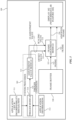
- FIG. 3 illustrates an example system architecture that may be implemented by the electronic device 100 in accordance with one or more implementations of the subject technology.
- the system architecture may implement techniques to automatically adjust the rendering and displaying of an application user interface such that the user interface does not intersect with the display's irregular feature or shape.
- the architecture of FIG. 3 is described as being implemented based on the depicted components of the electronic device 100, by using a processor and/or memory of the electronic device 100.
- the depicted components may be used in all implementations, and one or more implementations may include additional or different components than those shown in the FIG. 3 . Variations in the arrangement and type of the components may be made without departing from the scope of the claims as set forth herein.
- the electronic device 100 includes system processes 305 including a trigger module 310 and an adjustment value module 315, a frame buffer 320, a frame adjustment module 325, and the display 102 (discussed above with respect to FIG. 1 ).
- the frame buffer 320 stores a frame 322 that represents all the content including a user interface of the application to be rendered on the display 102.
- the frame buffer 320 may be a contiguous high throughput memory in which each element of the frame 322 in the frame buffer 320 corresponds to a single pixel on the display 102. The intensity of each pixel may be in accordance with a voltage value applied to the corresponding element of the frame buffer 320.
- the frame 322 may be two-dimensional array having element values corresponding to the two-dimensional pixel array of the display 102.
- every memory cell in the frame buffer 320 may correspond to a single pixel.
- each of these n bits may a separate bit plane (e.g. 24-bit color will have 24 bit planes).
- the binary values from each of the n bit planes may be loaded into corresponding positions in a register of a system memory.
- the resulting binary number is interpreted as an intensity level between 0 to 2 n - 1, and the intensity level is then converted into an analog voltage between 0 and the maximum voltage by a digital-to-analog converter, hence enabling 2 n intensity levels.
- An array of such voltage values (corresponding to the pixels of the display 102) form the frame 322 stored in the frame buffer 320.
- one or more applications executable on the electronic device 100 may be configured with a user interface which, when rendered, by default would be presented on the display 102 such that the user interface is at least partially obstructed by the irregular feature 104.
- the operating system or the system processes 305 (separate from the applications) of the electronic device 100 may identify, create, store (in a memory of the device 100), and update a list of applications 311 along with their respective user interfaces' incompatibility issues.
- the corresponding incompatibility issue(s) may indicate a state or a manner in which the user interface of the application, when rendered, would intersect with the irregular feature 104 of the display 102 (and thus, be considered incompatible with the display 102).
- the operating system may identify the Application 2 as having a "UI element" incompatibility issue in which when the user interface is rendered to be presented on the display 102, the one or more static UI elements of Application 2 are obscured by the notch 105. Additionally, or alternatively, the operating system (or other system processes) executing on the electronic device 100 may identify and store other incompatibility issues indicating operational states or conditions of the applications in which at least portions of the corresponding user interfaces get covered or hidden on the display due to its irregular feature or shape.
- the system processes 305 including the trigger module 310 and the adjustment value module 315 may receive and process application information 312 identifying an application which is currently "in focus," i.e., the application of which the user interface is to be rendered for displaying on the foreground of the display 102.
- the application information 312 (to be processed by the system processes 305) may also include state information of the application indicating a state of the user interface of the application. For example, the state information may indicate if the user interface is to be rendered and displayed in the full-screen mode on the display 102, or if the user interface includes a specific UI element which, when rendered, would have coordinates overlapping with the coordinates of the irregular feature 104 on the display 102.
- the trigger module 310 may receive and process the application information 312 to determine whether a triggering condition is present such that the user interface of the in-focus application is to be adjusted to avoid being obscured by the irregular feature(s) of the display. For example, based on the application information 312, the trigger module 310 may determine (a) whether the identified in-focus application is one of the applications in the list of applications predetermined by the operating system as having incompatibility issue(s), and (b) whether the state information indicates a user-interface state that is identified in the list as an incompatibility issue (e.g., full-screen issue, UI issue, or due to movement of the user interface into the portion of the display that includes the irregular feature) for the in-focus application.
- a user may indicate that a given application may have incompatibility issues, such as by checking a box or selecting another UI element corresponding to the given application.
- the trigger module 310 may determine that a trigger condition exists and generate a trigger condition signal 314.
- the trigger condition signal 314 may indicate activation of further modules and processes of the architecture to effectuate adjustment of the user interface so as to avoid or account for the irregular feature 104 when displayed on the display 102.
- the application information 312 may include an affirmative user input to the system processes specifying that the user requires the user interface of the in-focus application to be adjusted (e.g., to avoid or account for the irregular feature 104), regardless of whether either of the above-discussed conditions (a) and (b) is true.
- the trigger condition signal 314 represents an adjustment mode for the application activated based on the user input.
- the application information 312 may include a preference value embedded in the application (by the developer), the preference value indicating that the user interface of the application is to be adjusted (e.g., to avoid or account for the irregular feature 104), regardless of whether either of the above-discussed conditions (a) and (b) is true.
- the trigger condition signal 314 represents an adjustment mode for the application activated based on the embedded preference value.
- the operating system can identify triggering events or conditions without receiving any specific triggering instructions or data, thereby allowing the operating system to render adjusted frames for applications that have not been updated for use with the display 102. This allows existing applications to execute and display on new devices with new (non-rectangular) display geometries.
- the adjustment value module 315 may receive and process the trigger condition signal 314 to determine a user interface (UI) adjustment value 317.
- the UI adjustment value 317 may include a scaling value 318 and an offset value 319.
- the scaling value 318 may be used to scale values of a frame 322 from the frame buffer 320 to obtain an adjusted frame 326.
- the adjusted frame 326 may represent the frame 322 that has been shrunk or expanded in terms of the display resolution (in both height and width) in accordance with the scaling value 318.
- the offset value 319 may be used to rectilinearly move values of a frame 322 from the frame buffer 320 to obtain an adjusted frame 326.
- the adjusted frame 326 may represent the frame 322 that has been rectilinearly moved (in the horizontal and/or vertical direction) relative to the display 102's coordinates in accordance with the offset value 319.
- the UI adjustment of scaling and/or offsetting may be animated.
- the UI adjustment value 317 (one or both of the scaling value 318 and the offset value 319) may represent an adjustment to the frame 322 from the frame buffer 320 such that, when the adjusted frame 326 is rendered, the application's user interface is presented on the display 102 except on the predefined portion, e.g., the region 108 (including the irregular feature 104 or the notch 105) of the display 102.
- the frame adjustment module 325 may receive and process the frame 322 and the UI adjustment value 317 including the scaling value 318 and/or the offset value 319 to generate an adjusted frame 326.
- the application's user interface is modified such that when presented, the user interface is displayed on the display 102 except on the predefined portion, e.g., the region 108 of the display 102, thus avoiding the irregular feature 104 or the notch 105 (e.g., as discussed below in reference to FIGs. 4A-4B and FIGs. 5A-5B ).
- the frame adjustment module 325 may apply the scaling value 318 to scale the frame 322 to obtain an adjusted frame 326.
- the frame adjustment module 325 may shrink (or expand) the size of the frame 322 in both height and width in accordance with the scaling value 318, such that the adjusted frame 326 when presented on the display 102 would have a lower resolution as compared to a presentation of the frame 322.
- the scaling value 318 may represent a reduction in the size of the frame 322 to 99% or 98% or 97% of its original size, although these reduction values are not limiting.
- the frame adjustment module 325 may apply the offset value 319 to the frame 322 to obtain an adjusted frame 326.
- the frame adjustment module 325 may rectilinearly move (in the horizontal and/or vertical direction) the frame 322 relative to the display 102's coordinates in accordance with the offset value 319, such that the adjusted frame 326 when presented on the display 102 would have a rectilinearly-displaced presentation as compared to a presentation of the frame 322.
- the top edge of the application's user interface may be placed starting at a lower (vertical) coordinate position on the display 102 as compared to the placement of the same user interface on the display 102 if the (unadjusted) frame 322 were to be rendered.
- the rendering of the adjusted frame 326 is performed by using a hardware module (e.g., processor, chipset, integrated circuit, etc.) that is constructed to perform the rendering in accordance with the UI adjustment value 317 without causing flashing or unwanted artifacts typically resulting from display setting changes on conventional computing systems.
- a hardware module e.g., processor, chipset, integrated circuit, etc.
- the applying of the UI adjustment value 317 to the frame 322 may change the appearance of all the content including the user interface of the in-focus application being displayed by the display 102. However, the change in the appearance would be effective until the triggering condition is present (as detected by the trigger module 310, discussed above).
- the frame adjustment module 325 terminates application of the UI adjustment value 317 to the frame 322, and the frame 322 is rendered to display the user interface of the application on the display 102.
- FIGs. 4A, 4B depict a use case of the subject technology in which adjustment of the user interface of an application having the full-screen incompatibility issue is illustrated.
- a window 103-3 of an in-focus application is displayed in the full-screen mode on the display 102 of the electronic device 100.
- a portion of a header 405 of the window 103-3 intersects with and is thus obscured by the notch 105.
- the trigger module 310 may determine that a triggering condition for the window 103-3 of the in-focus application is present.
- the adjustment value module 315 may determine a suitable UI adjustment value 317, and the frame adjustment module 325 may apply the UI adjustment value 317 to a frame 322 corresponding to content including the window 103-3 to obtain an adjusted frame 326.
- the frame 322 may represent content including the window 103-3 to be rendered on the display 102.
- the UI adjustment value 317 may represent an adjustment to the frame 322 such that, when the adjusted frame 326 is rendered, the window 103-3 is presented on the display 102 except on the predefined region 108 including the notch 105 of the display 102. As shown in FIG.
- the adjusted frame 326 is rendered and presented as an adjusted window 103-3A, which may be smaller than and/or downward displaced as compared to the window 103-3.
- the scaling and rectilinear movement adjustments to the window 103-3 may be based on the scaling value 318 and the offset value 319, respectively.
- the UI adjustment of scaling and/or offsetting may be animated. As shown, the top edge of a header 405A of the window 103-3A is displayed below the predefined region 108 thus avoiding the visual intersection of the window with the notch 105.
- FIGs. 5A, 5B depict another use case of the subject technology in which adjustment of the user interface of an application having the UI element incompatibility issue is illustrated.
- the user interface of an in-focus application may include a window 103-4-1 and a UI element 103-4-2, both of which are displayed on the display 102 of the electronic device 100.
- a portion of UI element 103-4-2 intersects with and is thus obscured by the notch 105.
- the trigger module 310 may determine that a triggering condition in relation to the UI element 103-4-2 is present.
- the adjustment value module 315 may determine a suitable UI adjustment value 317, and the frame adjustment module 325 may apply the UI adjustment value 317 to a frame 322 corresponding to all the content on the display 102 including the UI element 103-4-2 to obtain an adjusted frame 326.
- the UI adjustment value 317 may represent an adjustment to the frame 322 such that, when the adjusted frame 326 is rendered, the UI element 103-4-2 is presented on the display 102 except on the predefined region 108 including the notch 105 of the display 102.
- the adjusted frame 326 is rendered and presented including an adjusted UI element 103-4-2A and an adjusted window 103-4-1A.
- the adjusted window 103-4-1A and the adjusted UI element 103-4-2A may be smaller than and/or downward displaced as compared to the window 103-4-1 and the UI element 103-4-2, respectively.
- the scaling and rectilinear movement adjustments to the window 103-4-1 and the UI element 103-4-2 may be based on the scaling value 318 and the offset value 319, respectively.
- the UI element 103-4-2 is displayed below the predefined region 108 thus avoiding the visual intersection of the UI element with the notch 105.
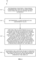
- FIG. 6 illustrates a flow diagram of an example process for displaying applications on a display while avoiding or accounting for the display's irregular or undesirable features in accordance with one or more implementations.
- the process 600 is primarily described herein with reference to the device 300 of FIG. 3 .
- the blocks of the process 600 are described herein as occurring in serial, or linearly. However, multiple blocks of the process 600 may occur in parallel.
- the blocks of the process 600 need not be performed in the order shown and/or one or more blocks of the process 600 need not be performed and/or can be replaced by other operations.
- the process 600 includes determining, using, e.g., the trigger module 310, whether a triggering condition related to an in-focus application executing on an electronic device 100 is present.
- the process 600 includes, responsive to a determination by the trigger module 310 that the triggering condition is present (as indicated by the trigger condition signal 314), determining, using the adjustment value module 315, a user interface (UI) adjustment value 317.
- UI user interface
- the process 600 includes applying, using the frame adjustment module 325, the UI adjustment value 317 to a frame 322 to obtain an adjusted frame 326.
- the frame 322 may represent content including a user interface of the application to be rendered on the display 102 of the electronic device 100.
- the UI adjustment value 317 may represent an adjustment to the frame 322 such that, when the adjusted frame 326 is rendered, the user interface of the application is presented on the display 102 except on a predefined portion (e.g., the region 108) of the display 102.
- the process 600 includes rendering, using the processor, the adjusted frame 326 to present the user interface of the application on the display 102 except on the predefined portion (e.g., the region 108) of the display 102.
- this gathered data may include personal information data that uniquely identifies or can be used to identify a specific person.
- personal information data can include voice samples, voice profiles, demographic data, location-based data, online identifiers, telephone numbers, email addresses, home addresses, biometric data or records relating to a user's health or level of fitness (e.g., vital signs measurements, medication information, exercise information), date of birth, or any other personal information.
- the present disclosure recognizes that the use of such personal information data, in the present technology, can be used to the benefit of users.
- the personal information data can be used for identifying a user of the device on which the disclosed techniques are being implemented and executed, or identifying a user profile in accordance with which the application (that is subject to the disclosed techniques) is being executed.
- the present disclosure contemplates that those entities responsible for the collection, analysis, disclosure, transfer, storage, or other use of such personal information data will comply with well-established privacy policies and/or privacy practices.
- such entities would be expected to implement and consistently apply privacy practices that are generally recognized as meeting or exceeding industry or governmental requirements for maintaining the privacy of users.
- Such information regarding the use of personal data should be prominently and easily accessible by users, and should be updated as the collection and/or use of data changes.
- Personal information from users should be collected for legitimate uses only. Further, such collection/sharing should occur only after receiving the consent of the users or other legitimate basis specified in applicable law. Additionally, such entities should consider taking any needed steps for safeguarding and securing access to such personal information data and ensuring that others with access to the personal information data adhere to their privacy policies and procedures.
- policies and practices should be adapted for the particular types of personal information data being collected and/or accessed and adapted to applicable laws and standards, including jurisdiction-specific considerations which may serve to impose a higher standard. For instance, in the US, collection of or access to certain health data may be governed by federal and/or state laws, such as the Health Insurance Portability and Accountability Act (HIPAA); whereas health data in other countries may be subject to other regulations and policies and should be handled accordingly.
- HIPAA Health Insurance Portability and Accountability Act
- the present disclosure also contemplates aspects in which users selectively block the use of, or access to, personal information data. That is, the present disclosure contemplates that hardware and/or software elements can be provided to prevent or block access to such personal information data.
- the present technology can be configured to allow users to select to "opt in” or “opt out” of participation in the collection and/or sharing of personal information data during registration for services or anytime thereafter.
- the present disclosure contemplates providing notifications relating to the access or use of personal information. For instance, a user may be notified upon downloading an app that their personal information data will be accessed and then reminded again just before personal information data is accessed by the app.
- personal information data should be managed and handled in a way to minimize risks of unintentional or unauthorized access or use. Risk can be minimized by limiting the collection of data and deleting data once it is no longer needed.
- data de-identification can be used to protect a user's privacy. De-identification may be facilitated, when appropriate, by removing identifiers, controlling the amount or specificity of data stored (e.g., collecting location data at city level rather than at an address level or at a scale that is insufficient for facial recognition), controlling how data is stored (e.g., aggregating data across users), and/or other methods such as differential privacy.
- the present disclosure broadly covers use of personal information data to implement one or more various disclosed aspects, the present disclosure also contemplates that the various aspects can also be implemented without the need for accessing such personal information data. That is, the various aspects of the present technology are not rendered inoperable due to the lack of all or a portion of such personal information data.
- FIG. 7 illustrates an electronic system 700 with which one or more implementations of the subject technology may be implemented.
- the electronic system 700 can be, and/or can be a part of the device 100, as shown in FIG. 1 , or the devices illustrated in FIG. 2 and FIG. 3 .
- the electronic system 700 may include various types of computer readable media and interfaces for various other types of computer readable media.
- the electronic system 700 includes a bus 708, one or more processing unit(s) 712, a system memory 704 (and/or buffer), a ROM 710, a permanent storage device 702, an input device interface 714, an output device interface 706, and one or more network interfaces 716, or subsets and variations thereof.
- the bus 708 collectively represents all system, peripheral, and chipset buses that communicatively connect the numerous internal devices of the electronic system 700.
- the bus 708 communicatively connects the one or more processing unit(s) 712 with the ROM 710, the system memory 704, and the permanent storage device 702. From these various memory units, the one or more processing unit(s) 712 retrieves instructions to execute and data to process in order to execute the processes of the subject disclosure.
- the one or more processing unit(s) 712 can be a single processor or a multi-core processor in different implementations.
- the ROM 710 stores static data and instructions that are needed by the one or more processing unit(s) 712 and other modules of the electronic system 700.
- the permanent storage device 702 may be a read-and-write memory device.
- the permanent storage device 702 may be a non-volatile memory unit that stores instructions and data even when the electronic system 700 is off.
- a mass-storage device (such as a magnetic or optical disk and its corresponding disk drive) may be used as the permanent storage device 702.
- a removable storage device such as a floppy disk, flash drive, and its corresponding disk drive
- the system memory 704 may be a read-and-write memory device. However, unlike the permanent storage device 702, the system memory 704 may be a volatile read-and-write memory, such as random access memory.
- the system memory 704 may store any of the instructions and data that one or more processing unit(s) 712 may need at runtime.
- the processes of the subject disclosure are stored in the system memory 704, the permanent storage device 702, and/or the ROM 710 (which are each implemented as a non-transitory computer-readable medium). From these various memory units, the one or more processing unit(s) 712 retrieves instructions to execute and data to process in order to execute the processes of one or more implementations.
- the bus 708 also connects to the input and output device interfaces 714 and 706.
- the input device interface 714 enables a user to communicate information and select commands to the electronic system 700.
- Input devices that may be used with the input device interface 714 may include, for example, alphanumeric keyboards and pointing devices (also called “cursor control devices").
- the output device interface 706 may enable, for example, the display of images generated by electronic system 700.
- Output devices that may be used with the output device interface 706 may include, for example, printers and display devices, such as a liquid crystal display (LCD), a light emitting diode (LED) display, an organic light emitting diode (OLED) display, a flexible display, a flat panel display, a solid state display, a projector, or any other device for outputting information.
- printers and display devices such as a liquid crystal display (LCD), a light emitting diode (LED) display, an organic light emitting diode (OLED) display, a flexible display, a flat panel display, a solid state display, a projector, or any other device for outputting information.
- One or more implementations may include devices that function as both input and output devices, such as a touchscreen.
- feedback provided to the user can be any form of sensory feedback, such as visual feedback, auditory feedback, or tactile feedback; and input from the user can be received in any form, including acoustic, speech, or tactile input.
- the bus 708 also couples the electronic system 700 to one or more networks and/or to one or more network nodes through the one or more network interface(s) 716.
- the electronic system 700 can be a part of a network of computers (such as a LAN, a wide area network ("WAN"), or an Intranet, or a network of networks, such as the Internet. Any or all components of the electronic system 700 can be used in conjunction with the subject disclosure.
- Some implementations include electronic components, such as microprocessors, storage and memory that store computer program instructions in a machine-readable or computer-readable medium (also referred to as computer-readable storage media, machine-readable media, or machine-readable storage media).
- computer-readable media include RAM, ROM, read-only compact discs (CD-ROM), recordable compact discs (CD-R), rewritable compact discs (CD-RW), read-only digital versatile discs (e.g., DVD-ROM, dual-layer DVD-ROM), a variety of recordable/rewritable DVDs (e.g., DVD-RAM, DVD-RW, DVD+RW, etc.), flash memory (e.g., SD cards, mini-SD cards, micro-SD cards, etc.), magnetic and/or solid state hard drives, read-only and recordable Blu-Ray ® discs, ultra density optical discs, any other optical or magnetic media, and floppy disks.
- CD-ROM compact discs
- CD-R recordable compact discs
- the computer-readable media can store a computer program that is executable by at least one processing unit and includes sets of instructions for performing various operations.
- Examples of computer programs or computer code include machine code, such as is produced by a compiler, and files including higher-level code that are executed by a computer, an electronic component, or a microprocessor using an interpreter.
- ASICs application specific integrated circuits
- FPGAs field programmable gate arrays
- integrated circuits execute instructions that are stored on the circuit itself.
- the terms "computer”, “server”, “processor”, and “memory” all refer to electronic or other technological devices. These terms exclude people or groups of people.
- display or displaying means displaying on an electronic device.
- computer readable medium and “computer readable media” are entirely restricted to tangible, physical objects that store information in a form that is readable by a computer. These terms exclude any wireless signals, wired download signals, and any other ephemeral signals.
- implementations of the subject matter described in this specification can be implemented on a computer having a display device, e.g., a CRT (cathode ray tube) or LCD (liquid crystal display) monitor, for displaying information to the user and a keyboard and a pointing device, e.g., a mouse or a trackball, by which the user can provide input to the computer.
- a display device e.g., a CRT (cathode ray tube) or LCD (liquid crystal display) monitor
- a keyboard and a pointing device e.g., a mouse or a trackball
- Other kinds of devices can be used to provide for interaction with a user as well; e.g., feedback provided to the user can be any form of sensory feedback, e.g., visual feedback, auditory feedback, or tactile feedback; and input from the user can be received in any form, including acoustic, speech, or tactile input.
- a computer can interact with a user by sending documents to and receiving documents from
- aspects of the subject matter described in this specification can be implemented in a computing system that includes a back end component, e.g., as a data server, or that includes a middleware component, e.g., an application server, or that includes a front end component, e.g., a client computer having a graphical user interface or a Web browser through which a user can interact with an implementation of the subject matter described in this specification, or any combination of one or more such back end, middleware, or front end components.
- the components of the system can be interconnected by any form or medium of digital data communication, e.g., a communication network.
- Examples of communication networks include a local area network (“LAN”) and a wide area network (“WAN”), an inter-network (e.g., the Internet), and peer-to-peer networks (e.g., ad hoc peer-to-peer networks).
- LAN local area network
- WAN wide area network
- inter-network e.g., the Internet
- peer-to-peer networks e.g., ad hoc peer-to-peer networks.
- a method includes determining whether a triggering condition related to an application executing on an electronic device is present, and if so, determining a user interface (UI) adjustment value.
- the UI adjustment value is applied to a frame that represents all of the content including a user interface of the application to be rendered on the display.
- the UI adjustment value represents an adjustment to the frame such that, when the adjusted frame is rendered, the user interface of the application is presented on the display except on a predefined portion (e.g., a portion including an irregular feature or region) of the display.
- the adjusted frame is then rendered to present the user interface of the application on the display except on the predefined portion of the display.
- a device in accordance with aspects of the disclosure, includes at least one processor; and a memory including instructions that, when executed by the at least one processor, cause the at least one processor to determine whether a triggering condition related to an application executing on an electronic device is present, and if so, determine a user interface (UI) adjustment value.
- the instructions when executed, further cause the at least one processor to apply the UI adjustment value to a frame that represents all of the content including a user interface of the application to be rendered on the display.
- the UI adjustment value represents an adjustment to the frame such that, when the adjusted frame is rendered, the user interface of the application is presented on the display except on a predefined portion (e.g., a portion including an irregular feature or region) of the display.
- the instructions when executed, further cause the at least one processor to render the adjusted frame to present the user interface of the application on the display except on the predefined portion of the display.
- Pronouns in the masculine include the feminine and neuter gender (e.g., her and its) and vice versa. Headings and subheadings, if any, are used for convenience only and do not limit the disclosure described herein.
- a processor configured to monitor and control an operation or a component may also mean the processor being programmed to monitor and control the operation or the processor being operable to monitor and control the operation.
- a processor configured to execute code can be construed as a processor programmed to execute code or operable to execute code.
- automatic may include performance by a computer or machine without user intervention; for example, by instructions responsive to a predicate action by the computer or machine or other initiation mechanism.
- the word "example” is used herein to mean “serving as an example or illustration.” Any aspect or design described herein as “example” is not necessarily to be construed as preferred or advantageous over other aspects or designs.
Landscapes
- Engineering & Computer Science (AREA)
- Theoretical Computer Science (AREA)
- Physics & Mathematics (AREA)
- General Physics & Mathematics (AREA)
- General Engineering & Computer Science (AREA)
- Computer Hardware Design (AREA)
- Human Computer Interaction (AREA)
- User Interface Of Digital Computer (AREA)
Claims (15)
- Verfahren zum Anzeigen einer Anwendungsbenutzeroberfläche auf einer Anzeige einer elektronischen Vorrichtung, das Verfahren umfassend:Bestimmen, unter Verwendung eines Prozessors der elektronischen Vorrichtung, ob eine Auslösebedingung bezüglich einer Anwendung vorliegt, die auf der elektronischen Vorrichtung (100) ausgeführt wird, wobei die Auslösebedingung bestimmt wird, wenn die Anwendung im Fokus ist und wenn bestimmt wird, dass angegeben ist, dass die Anwendung eine Benutzeroberfläche, UI, mit einem Kompatibilitätsproblem mit einem vordefinierten Teil (104, 105, 108) der Anzeige (102) der elektronischen Vorrichtung aufweist;als Reaktion auf eine Bestimmung, dass die Auslösebedingung vorliegt, Bestimmen, unter Verwendung des Prozessors, eines UI-Anpassungswerts (317), der UI-Anpassungswert einschließlich eines Versatzwerts (319);Anwenden, unter Verwendung des Prozessors, des UI-Anpassungswerts auf ein Einzelbild (322), um ein angepasstes Einzelbild zu erhalten, wobei das Einzelbild gemäß dem Versatzwert geradlinig bewegt wird, um das angepasste Einzelbild (326) zu erhalten, wobei das Einzelbild den gesamten Inhalt darstellt, der auf der Anzeige der elektronischen Vorrichtung wiedergegeben werden soll, der Inhalt einschließlich einer Benutzeroberfläche der Anwendung, und der UI-Anpassungswert eine Anpassung des Einzelbilds derart darstellt, dass, wenn das angepasste Einzelbild wiedergegeben wird, die Benutzeroberfläche der Anwendung auf der Anzeige mit Ausnahme des vordefinierten Teils der Anzeige dargestellt wird; undWiedergeben, unter Verwendung des Prozessors, des angepassten Einzelbilds, um die Benutzeroberfläche der Anwendung auf der Anzeige darzustellen, mit Ausnahme des vordefinierten Teils der Anzeige.
- Verfahren nach Anspruch 1, wobei der UI-Anpassungswert ferner einen Skalierungswert (318) einschließt, wobei das Einzelbild gemäß dem Skalierungswert skaliert wird, um das angepasste Einzelbild zu erhalten.
- Verfahren nach einem der Ansprüche 1 bis 2, wobei die Auslösebedingung eines oder mehrere von einer Aktivierung eines Vollbildmodus zum Anzeigen der Benutzeroberfläche der Anwendung, einer Bewegung der Benutzeroberfläche der Anwendung in den vordefinierten Teil der Anzeige und der Aktivierung eines gewissen UI-Elements der Benutzeroberfläche der Anwendung einschließt.
- Verfahren nach einem der Ansprüche 1 bis 3, wobei die Auslösebedingung eine Benutzereingabe einschließt, die einen Anpassungsmodus für die Anwendung aktiviert.
- Verfahren nach einem der Ansprüche 1 bis 4, wobei die Auslösebedingung einen Präferenzwert einschließt, der in die Anwendung eingebettet ist, wobei der Präferenzwert die Aktivierung eines Anpassungsmodus für die Anwendung angibt.
- Verfahren nach einem der Ansprüche 1 bis 5, ferner umfassend als Reaktion auf eine Bestimmung, dass die Auslösebedingung nicht mehr vorliegt, ein Beenden der Anwendung des UI-Anpassungswerts auf das Einzelbild; und Wiedergeben des Einzelbilds, um die Benutzeroberfläche der Anwendung auf der Anzeige darzustellen.
- Verfahren nach einem der Ansprüche 1 bis 6, wobei der vordefinierte Teil der Anzeige eines oder mehrere einer Kerbe, eines Schlüssellochs, einer Kante der Anzeige und eines Anzeigebereichs einschließt, unter dem eine elektronische Komponente eingebettet ist.
- Verfahren nach einem der Ansprüche 1 bis 7, wobei die Anzeige eine nicht rechteckige Form aufweist.
- Verfahren nach einem der Ansprüche 1 bis 8, ferner umfassend ein Animieren des Anwendens des UI-Anpassungswerts.
- Elektronische Vorrichtung, umfassend:eine Anzeige,mindestens einen Prozessor; undeinen Speicher, einschließlich Anweisungen, die, wenn sie durch den mindestens einen Prozessor ausgeführt werden, den mindestens einen Prozessor veranlassen zum:Bestimmen, ob eine Auslösebedingung bezüglich einer Anwendung vorliegt, die auf der elektronischen Vorrichtung ausgeführt wird, wobei die Auslösebedingung bestimmt wird, wenn die Anwendung im Fokus ist und wenn bestimmt wird, dass angegeben ist, dass die Anwendung eine Benutzeroberfläche, UI, mit einem Kompatibilitätsproblem mit einem vordefinierten Teil einer Anzeige der elektronischen Vorrichtung aufweist;als Reaktion auf eine Bestimmung, dass die Auslösebedingung vorliegt, Bestimmen, eines UI-Anpassungswerts, der UI-Anpassungswert einschließlich eines Versatzwerts;Anwenden des UI-Anpassungswerts auf ein Einzelbild, um ein angepasstes Einzelbild zu erhalten, wobei das Einzelbild gemäß dem Versatzwert geradlinig bewegt wird, um das angepasste Einzelbild zu erhalten, wobei das Einzelbild den gesamten Inhalt darstellt, der auf der Anzeige der elektronischen Vorrichtung wiedergegeben werden soll, der Inhalt einschließlich einer Benutzeroberfläche der Anwendung, und der UI-Anpassungswert eine Anpassung des Einzelbilds derart darstellt, dass, wenn das angepasste Einzelbild wiedergegeben wird, die Benutzeroberfläche der Anwendung auf der Anzeige mit Ausnahme des vordefinierten Teils der Anzeige dargestellt wird; undWiedergeben des angepassten Einzelbilds, um die Benutzeroberfläche der Anwendung auf der Anzeige darzustellen, mit Ausnahme des vordefinierten Teils der Anzeige.
- Vorrichtung nach Anspruch 10,wobei der UI-Anpassungswert ferner einen Skalierungswert einschließt, wobei das Einzelbild gemäß dem Skalierungswert skaliert wird, um das angepasste Einzelbild zu erhalten, und/oderwobei die Auslösebedingung eines oder mehrere von einer Aktivierung eines Vollbildmodus zum Anzeigen der Benutzeroberfläche der Anwendung, einer Bewegung der Benutzeroberfläche der Anwendung in den vordefinierten Teil der Anzeige und der Aktivierung eines gewissen UI-Elements der Benutzeroberfläche der Anwendung einschließt, und/oderwobei die Auslösebedingung eine Benutzereingabe einschließt, die einen Anpassungsmodus für die Anwendung aktiviert, und/oderwobei die Auslösebedingung einen Präferenzwert einschließt, der in die Anwendung eingebettet ist, wobei der Präferenzwert die Aktivierung eines Anpassungsmodus für die Anwendung angibt.
- Vorrichtung nach einem der Ansprüche 10 bis 11, wobei die Anweisungen, wenn sie durch den mindestens einen Prozessor ausgeführt werden, ferner den mindestens einen Prozessor veranlassen zum: als Reaktion auf eine Bestimmung, dass die Auslösebedingung nicht mehr vorliegt, Beenden der Anwendung des UI-Anpassungswerts auf das Einzelbild; und Wiedergeben des Einzelbilds, um die Benutzeroberfläche der Anwendung auf der Anzeige darzustellen.
- Vorrichtung nach einem der Ansprüche 10 bis 12,wobei der vordefinierte Teil der Anzeige eines oder mehrere einer Kerbe, eines Schlüssellochs, einer Kante der Anzeige und eines Anzeigebereichs einschließt, unter dem eine elektronische Komponente eingebettet ist, und/oderwobei die Anzeige eine nicht rechteckige Form aufweist.
- Nichtflüchtiges computerlesbares Medium, umfassend Anweisungen, die, wenn sie durch mindestens eine elektronische Vorrichtung, umfassend eine Anzeige, ausgeführt werden, die mindestens eine elektronische Vorrichtung veranlassen, Abläufe durchzuführen, umfassend:Bestimmen, ob eine Auslösebedingung bezüglich einer Anwendung vorliegt, die auf einer elektronischen Vorrichtung ausgeführt wird, wobei die Auslösebedingung bestimmt wird, wenn die Anwendung im Fokus ist und wenn bestimmt wird, dass angegebene ist, dass die Anwendung eine Benutzeroberfläche, UI, mit einem Kompatibilitätsproblem mit einem vordefinierten Teil einer Anzeige der elektronischen Vorrichtung aufweist;als Reaktion auf eine Bestimmung, dass die Auslösebedingung vorliegt, Bestimmen, eines UI-Anpassungswerts, der UI-Anpassungswert einschließlich eines Versatzwerts;Anwenden des UI-Anpassungswerts auf ein Einzelbild, um ein angepasstes Einzelbild zu erhalten, wobei das Einzelbild gemäß dem Versatzwert geradlinig bewegt wird, um das angepasste Einzelbild zu erhalten, wobei das Einzelbild den gesamten Inhalt darstellt, der auf der Anzeige der elektronischen Vorrichtung wiedergegeben werden soll, der Inhalt einschließlich einer Benutzeroberfläche der Anwendung, und der UI-Anpassungswert eine Anpassung des Einzelbilds derart darstellt, dass, wenn das angepasste Einzelbild wiedergegeben wird, die Benutzeroberfläche der Anwendung auf der Anzeige mit Ausnahme des vordefinierten Teils der Anzeige dargestellt wird; undWiedergeben des angepassten Einzelbilds, um die Benutzeroberfläche der Anwendung auf der Anzeige darzustellen, mit Ausnahme des vordefinierten Teils der Anzeige.
- Nichtflüchtiges computerlesbares Medium nach Anspruch 14, wobei der UI-Anpassungswert ferner einen Skalierungswert einschließt, wobei das Einzelbild gemäß dem Skalierungswert skaliert wird, um das angepasste Einzelbild zu erhalten.
Applications Claiming Priority (2)
| Application Number | Priority Date | Filing Date | Title |
|---|---|---|---|
| US202163243689P | 2021-09-13 | 2021-09-13 | |
| US17/943,070 US12236072B2 (en) | 2021-09-13 | 2022-09-12 | Displaying on a display with an irregular feature |
Publications (2)
| Publication Number | Publication Date |
|---|---|
| EP4148545A1 EP4148545A1 (de) | 2023-03-15 |
| EP4148545B1 true EP4148545B1 (de) | 2025-05-07 |
Family
ID=83546876
Family Applications (1)
| Application Number | Title | Priority Date | Filing Date |
|---|---|---|---|
| EP22195373.0A Active EP4148545B1 (de) | 2021-09-13 | 2022-09-13 | Anzeige auf einer anzeige mit unregelmässigem merkmal |
Country Status (4)
| Country | Link |
|---|---|
| US (1) | US12236072B2 (de) |
| EP (1) | EP4148545B1 (de) |
| KR (1) | KR102765618B1 (de) |
| CN (1) | CN115794005A (de) |
Family Cites Families (13)
| Publication number | Priority date | Publication date | Assignee | Title |
|---|---|---|---|---|
| JPH03292524A (ja) * | 1990-04-11 | 1991-12-24 | Oki Electric Ind Co Ltd | カーソル移動方式 |
| US8907957B2 (en) * | 2011-08-30 | 2014-12-09 | Apple Inc. | Automatic animation generation |
| CA2792188A1 (en) * | 2011-10-18 | 2013-04-18 | Research In Motion Limited | Method of animating a rearrangement of ui elements on a display screen of an electronic device |
| JP5927907B2 (ja) * | 2011-12-26 | 2016-06-01 | ブラザー工業株式会社 | 画像形成装置、画像形成装置の制御方法およびプログラム |
| DE112012005649T5 (de) * | 2012-01-12 | 2014-10-09 | Mitsubishi Electric Corporation | Kartenanzeigevorrichtung und Kartenanzeigeverfahren |
| GB2552090B (en) | 2017-06-29 | 2021-06-16 | Inodyn Newmedia Gmbh | Front-facing camera and maximized display screen of a mobile device |
| WO2018080542A1 (en) * | 2016-10-31 | 2018-05-03 | Hewlett-Packard Development Company, L.P. | Developing a non-rectangular user interface |
| US9959027B1 (en) | 2017-07-03 | 2018-05-01 | Essential Products, Inc. | Displaying an image on an irregular screen |
| JP2019070762A (ja) * | 2017-10-10 | 2019-05-09 | シャープ株式会社 | 電子機器、制御装置、電子機器の制御方法、および制御プログラム |
| JP2019185114A (ja) * | 2018-04-02 | 2019-10-24 | レノボ・シンガポール・プライベート・リミテッド | 情報処理装置、表示制御方法、及びプログラム |
| US10607375B2 (en) * | 2018-06-03 | 2020-03-31 | Apple Inc. | Encoding techniques |
| CN109308205B (zh) * | 2018-08-09 | 2020-12-01 | 腾讯科技(深圳)有限公司 | 应用程序的显示适配方法、装置、设备及存储介质 |
| CN110211537B (zh) * | 2018-08-22 | 2021-01-22 | 京东方科技集团股份有限公司 | 显示基板的驱动方法、驱动电路及显示装置 |
-
2022
- 2022-09-12 US US17/943,070 patent/US12236072B2/en active Active
- 2022-09-13 EP EP22195373.0A patent/EP4148545B1/de active Active
- 2022-09-13 CN CN202211111078.1A patent/CN115794005A/zh active Pending
- 2022-09-13 KR KR1020220114968A patent/KR102765618B1/ko active Active
Also Published As
| Publication number | Publication date |
|---|---|
| US20230082764A1 (en) | 2023-03-16 |
| US12236072B2 (en) | 2025-02-25 |
| CN115794005A (zh) | 2023-03-14 |
| KR20230039577A (ko) | 2023-03-21 |
| EP4148545A1 (de) | 2023-03-15 |
| KR102765618B1 (ko) | 2025-02-12 |
Similar Documents
| Publication | Publication Date | Title |
|---|---|---|
| US8411112B1 (en) | Systems and methods for generating an icon | |
| KR102073848B1 (ko) | 웹 브라우저를 위한 몰입 모드 | |
| EP4118514B1 (de) | Blickbasierte steuerung | |
| US10417991B2 (en) | Multi-display device user interface modification | |
| US8443297B1 (en) | Dimming a window that is out of focus | |
| US8769435B1 (en) | Systems and methods for resizing an icon | |
| US10990256B2 (en) | Modifying default display configurations for objects in a user interface | |
| US20150205447A1 (en) | Mobile device friendly window management for remote desktop | |
| US9335905B1 (en) | Content selection feedback | |
| US8510675B1 (en) | Hiding window borders | |
| US10955985B2 (en) | Optimizing an arrangement of content on a display of a user device based on user focus | |
| US12236072B2 (en) | Displaying on a display with an irregular feature | |
| US20220382566A1 (en) | Generating User Interface Containers | |
| US20180120966A1 (en) | Method and device for handling event invocation using a stylus pen | |
| US11662883B2 (en) | Adaptable user input interface | |
| US11270486B2 (en) | Electronic drawing with handwriting recognition | |
| US12346496B2 (en) | Adaptive blurring of virtual content | |
| US12487727B2 (en) | Sensory adjustment mechanism | |
| US10198153B1 (en) | Ordering items for switching |
Legal Events
| Date | Code | Title | Description |
|---|---|---|---|
| PUAI | Public reference made under article 153(3) epc to a published international application that has entered the european phase |
Free format text: ORIGINAL CODE: 0009012 |
|
| STAA | Information on the status of an ep patent application or granted ep patent |
Free format text: STATUS: THE APPLICATION HAS BEEN PUBLISHED |
|
| AK | Designated contracting states |
Kind code of ref document: A1 Designated state(s): AL AT BE BG CH CY CZ DE DK EE ES FI FR GB GR HR HU IE IS IT LI LT LU LV MC MK MT NL NO PL PT RO RS SE SI SK SM TR |
|
| STAA | Information on the status of an ep patent application or granted ep patent |
Free format text: STATUS: REQUEST FOR EXAMINATION WAS MADE |
|
| 17P | Request for examination filed |
Effective date: 20230915 |
|
| RBV | Designated contracting states (corrected) |
Designated state(s): AL AT BE BG CH CY CZ DE DK EE ES FI FR GB GR HR HU IE IS IT LI LT LU LV MC MK MT NL NO PL PT RO RS SE SI SK SM TR |
|
| STAA | Information on the status of an ep patent application or granted ep patent |
Free format text: STATUS: EXAMINATION IS IN PROGRESS |
|
| 17Q | First examination report despatched |
Effective date: 20231116 |
|
| GRAP | Despatch of communication of intention to grant a patent |
Free format text: ORIGINAL CODE: EPIDOSNIGR1 |
|
| STAA | Information on the status of an ep patent application or granted ep patent |
Free format text: STATUS: GRANT OF PATENT IS INTENDED |
|
| INTG | Intention to grant announced |
Effective date: 20241203 |
|
| GRAS | Grant fee paid |
Free format text: ORIGINAL CODE: EPIDOSNIGR3 |
|
| GRAA | (expected) grant |
Free format text: ORIGINAL CODE: 0009210 |
|
| STAA | Information on the status of an ep patent application or granted ep patent |
Free format text: STATUS: THE PATENT HAS BEEN GRANTED |
|
| P01 | Opt-out of the competence of the unified patent court (upc) registered |
Free format text: CASE NUMBER: APP_11545/2025 Effective date: 20250310 |
|
| AK | Designated contracting states |
Kind code of ref document: B1 Designated state(s): AL AT BE BG CH CY CZ DE DK EE ES FI FR GB GR HR HU IE IS IT LI LT LU LV MC MK MT NL NO PL PT RO RS SE SI SK SM TR |
|
| REG | Reference to a national code |
Ref country code: GB Ref legal event code: FG4D |
|
| REG | Reference to a national code |
Ref country code: CH Ref legal event code: EP |
|
| REG | Reference to a national code |
Ref country code: DE Ref legal event code: R096 Ref document number: 602022014164 Country of ref document: DE |
|
| REG | Reference to a national code |
Ref country code: IE Ref legal event code: FG4D |
|
| REG | Reference to a national code |
Ref country code: NL Ref legal event code: MP Effective date: 20250507 |
|
| PG25 | Lapsed in a contracting state [announced via postgrant information from national office to epo] |
Ref country code: ES Free format text: LAPSE BECAUSE OF FAILURE TO SUBMIT A TRANSLATION OF THE DESCRIPTION OR TO PAY THE FEE WITHIN THE PRESCRIBED TIME-LIMIT Effective date: 20250507 Ref country code: PT Free format text: LAPSE BECAUSE OF FAILURE TO SUBMIT A TRANSLATION OF THE DESCRIPTION OR TO PAY THE FEE WITHIN THE PRESCRIBED TIME-LIMIT Effective date: 20250908 Ref country code: FI Free format text: LAPSE BECAUSE OF FAILURE TO SUBMIT A TRANSLATION OF THE DESCRIPTION OR TO PAY THE FEE WITHIN THE PRESCRIBED TIME-LIMIT Effective date: 20250507 |
|
| PGFP | Annual fee paid to national office [announced via postgrant information from national office to epo] |
Ref country code: DE Payment date: 20250929 Year of fee payment: 4 |
|
| REG | Reference to a national code |
Ref country code: LT Ref legal event code: MG9D |
|
| PG25 | Lapsed in a contracting state [announced via postgrant information from national office to epo] |
Ref country code: NO Free format text: LAPSE BECAUSE OF FAILURE TO SUBMIT A TRANSLATION OF THE DESCRIPTION OR TO PAY THE FEE WITHIN THE PRESCRIBED TIME-LIMIT Effective date: 20250807 Ref country code: GR Free format text: LAPSE BECAUSE OF FAILURE TO SUBMIT A TRANSLATION OF THE DESCRIPTION OR TO PAY THE FEE WITHIN THE PRESCRIBED TIME-LIMIT Effective date: 20250808 |
|
| PG25 | Lapsed in a contracting state [announced via postgrant information from national office to epo] |
Ref country code: NL Free format text: LAPSE BECAUSE OF FAILURE TO SUBMIT A TRANSLATION OF THE DESCRIPTION OR TO PAY THE FEE WITHIN THE PRESCRIBED TIME-LIMIT Effective date: 20250507 Ref country code: PL Free format text: LAPSE BECAUSE OF FAILURE TO SUBMIT A TRANSLATION OF THE DESCRIPTION OR TO PAY THE FEE WITHIN THE PRESCRIBED TIME-LIMIT Effective date: 20250507 |
|
| REG | Reference to a national code |
Ref country code: AT Ref legal event code: MK05 Ref document number: 1793199 Country of ref document: AT Kind code of ref document: T Effective date: 20250507 |
|
| PG25 | Lapsed in a contracting state [announced via postgrant information from national office to epo] |
Ref country code: BG Free format text: LAPSE BECAUSE OF FAILURE TO SUBMIT A TRANSLATION OF THE DESCRIPTION OR TO PAY THE FEE WITHIN THE PRESCRIBED TIME-LIMIT Effective date: 20250507 |
|
| PG25 | Lapsed in a contracting state [announced via postgrant information from national office to epo] |
Ref country code: HR Free format text: LAPSE BECAUSE OF FAILURE TO SUBMIT A TRANSLATION OF THE DESCRIPTION OR TO PAY THE FEE WITHIN THE PRESCRIBED TIME-LIMIT Effective date: 20250507 |
|
| PG25 | Lapsed in a contracting state [announced via postgrant information from national office to epo] |
Ref country code: AT Free format text: LAPSE BECAUSE OF FAILURE TO SUBMIT A TRANSLATION OF THE DESCRIPTION OR TO PAY THE FEE WITHIN THE PRESCRIBED TIME-LIMIT Effective date: 20250507 |
|
| PG25 | Lapsed in a contracting state [announced via postgrant information from national office to epo] |
Ref country code: RS Free format text: LAPSE BECAUSE OF FAILURE TO SUBMIT A TRANSLATION OF THE DESCRIPTION OR TO PAY THE FEE WITHIN THE PRESCRIBED TIME-LIMIT Effective date: 20250807 |
|
| PG25 | Lapsed in a contracting state [announced via postgrant information from national office to epo] |
Ref country code: IS Free format text: LAPSE BECAUSE OF FAILURE TO SUBMIT A TRANSLATION OF THE DESCRIPTION OR TO PAY THE FEE WITHIN THE PRESCRIBED TIME-LIMIT Effective date: 20250907 |
|
| PG25 | Lapsed in a contracting state [announced via postgrant information from national office to epo] |
Ref country code: LV Free format text: LAPSE BECAUSE OF FAILURE TO SUBMIT A TRANSLATION OF THE DESCRIPTION OR TO PAY THE FEE WITHIN THE PRESCRIBED TIME-LIMIT Effective date: 20250507 |
|
| PG25 | Lapsed in a contracting state [announced via postgrant information from national office to epo] |
Ref country code: DK Free format text: LAPSE BECAUSE OF FAILURE TO SUBMIT A TRANSLATION OF THE DESCRIPTION OR TO PAY THE FEE WITHIN THE PRESCRIBED TIME-LIMIT Effective date: 20250507 Ref country code: SM Free format text: LAPSE BECAUSE OF FAILURE TO SUBMIT A TRANSLATION OF THE DESCRIPTION OR TO PAY THE FEE WITHIN THE PRESCRIBED TIME-LIMIT Effective date: 20250507 |
|
| PG25 | Lapsed in a contracting state [announced via postgrant information from national office to epo] |
Ref country code: CZ Free format text: LAPSE BECAUSE OF FAILURE TO SUBMIT A TRANSLATION OF THE DESCRIPTION OR TO PAY THE FEE WITHIN THE PRESCRIBED TIME-LIMIT Effective date: 20250507 |
|
| PG25 | Lapsed in a contracting state [announced via postgrant information from national office to epo] |
Ref country code: EE Free format text: LAPSE BECAUSE OF FAILURE TO SUBMIT A TRANSLATION OF THE DESCRIPTION OR TO PAY THE FEE WITHIN THE PRESCRIBED TIME-LIMIT Effective date: 20250507 |
|
| PG25 | Lapsed in a contracting state [announced via postgrant information from national office to epo] |
Ref country code: SK Free format text: LAPSE BECAUSE OF FAILURE TO SUBMIT A TRANSLATION OF THE DESCRIPTION OR TO PAY THE FEE WITHIN THE PRESCRIBED TIME-LIMIT Effective date: 20250507 |
|
| PG25 | Lapsed in a contracting state [announced via postgrant information from national office to epo] |
Ref country code: IT Free format text: LAPSE BECAUSE OF FAILURE TO SUBMIT A TRANSLATION OF THE DESCRIPTION OR TO PAY THE FEE WITHIN THE PRESCRIBED TIME-LIMIT Effective date: 20250507 |
|
| PG25 | Lapsed in a contracting state [announced via postgrant information from national office to epo] |
Ref country code: RO Free format text: LAPSE BECAUSE OF FAILURE TO SUBMIT A TRANSLATION OF THE DESCRIPTION OR TO PAY THE FEE WITHIN THE PRESCRIBED TIME-LIMIT Effective date: 20250507 |
|
| REG | Reference to a national code |
Ref country code: DE Ref legal event code: R097 Ref document number: 602022014164 Country of ref document: DE |
|
| PLBE | No opposition filed within time limit |
Free format text: ORIGINAL CODE: 0009261 |
|
| STAA | Information on the status of an ep patent application or granted ep patent |
Free format text: STATUS: NO OPPOSITION FILED WITHIN TIME LIMIT |
|
| REG | Reference to a national code |
Ref country code: CH Ref legal event code: L10 Free format text: ST27 STATUS EVENT CODE: U-0-0-L10-L00 (AS PROVIDED BY THE NATIONAL OFFICE) Effective date: 20260318 |
|
| 26N | No opposition filed |
Effective date: 20260210 |
|
| REG | Reference to a national code |
Ref country code: CH Ref legal event code: H13 Free format text: ST27 STATUS EVENT CODE: U-0-0-H10-H13 (AS PROVIDED BY THE NATIONAL OFFICE) Effective date: 20260504 |