EP4148508A1 - System zur steuerung von heisswasserzylindern - Google Patents
System zur steuerung von heisswasserzylindern Download PDFInfo
- Publication number
- EP4148508A1 EP4148508A1 EP20934851.5A EP20934851A EP4148508A1 EP 4148508 A1 EP4148508 A1 EP 4148508A1 EP 20934851 A EP20934851 A EP 20934851A EP 4148508 A1 EP4148508 A1 EP 4148508A1
- Authority
- EP
- European Patent Office
- Prior art keywords
- hot water
- cylinder
- water
- controller
- energy
- Prior art date
- Legal status (The legal status is an assumption and is not a legal conclusion. Google has not performed a legal analysis and makes no representation as to the accuracy of the status listed.)
- Withdrawn
Links
- XLYOFNOQVPJJNP-UHFFFAOYSA-N water Substances O XLYOFNOQVPJJNP-UHFFFAOYSA-N 0.000 title claims abstract description 143
- 238000010438 heat treatment Methods 0.000 claims description 25
- 230000006399 behavior Effects 0.000 claims description 17
- 238000004891 communication Methods 0.000 claims description 12
- 230000003014 reinforcing effect Effects 0.000 claims description 7
- 238000005265 energy consumption Methods 0.000 abstract description 14
- 230000002159 abnormal effect Effects 0.000 abstract description 2
- 238000000605 extraction Methods 0.000 description 8
- 230000005611 electricity Effects 0.000 description 6
- 238000007726 management method Methods 0.000 description 5
- 238000005259 measurement Methods 0.000 description 5
- 230000001052 transient effect Effects 0.000 description 5
- 238000013528 artificial neural network Methods 0.000 description 4
- 230000008859 change Effects 0.000 description 4
- 230000006870 function Effects 0.000 description 4
- 230000009467 reduction Effects 0.000 description 4
- 238000009529 body temperature measurement Methods 0.000 description 3
- 238000009434 installation Methods 0.000 description 3
- 238000000034 method Methods 0.000 description 3
- 238000013473 artificial intelligence Methods 0.000 description 2
- 238000012417 linear regression Methods 0.000 description 2
- 230000002787 reinforcement Effects 0.000 description 2
- 206010000117 Abnormal behaviour Diseases 0.000 description 1
- 241001123248 Arma Species 0.000 description 1
- 230000003044 adaptive effect Effects 0.000 description 1
- 230000000295 complement effect Effects 0.000 description 1
- 239000004020 conductor Substances 0.000 description 1
- 230000008878 coupling Effects 0.000 description 1
- 238000010168 coupling process Methods 0.000 description 1
- 238000005859 coupling reaction Methods 0.000 description 1
- 238000001514 detection method Methods 0.000 description 1
- 238000004146 energy storage Methods 0.000 description 1
- 230000007613 environmental effect Effects 0.000 description 1
- 239000000284 extract Substances 0.000 description 1
- 239000008236 heating water Substances 0.000 description 1
- 238000009413 insulation Methods 0.000 description 1
- 229910052751 metal Inorganic materials 0.000 description 1
- 239000002184 metal Substances 0.000 description 1
- 150000002739 metals Chemical class 0.000 description 1
- 238000012544 monitoring process Methods 0.000 description 1
- 229920003223 poly(pyromellitimide-1,4-diphenyl ether) Polymers 0.000 description 1
- 230000008569 process Effects 0.000 description 1
- 230000003134 recirculating effect Effects 0.000 description 1
- 239000008399 tap water Substances 0.000 description 1
- 235000020679 tap water Nutrition 0.000 description 1
Images

Classifications
-
- F—MECHANICAL ENGINEERING; LIGHTING; HEATING; WEAPONS; BLASTING
- F24—HEATING; RANGES; VENTILATING
- F24H—FLUID HEATERS, e.g. WATER OR AIR HEATERS, HAVING HEAT-GENERATING MEANS, e.g. HEAT PUMPS, IN GENERAL
- F24H15/00—Control of fluid heaters
- F24H15/10—Control of fluid heaters characterised by the purpose of the control
- F24H15/156—Reducing the quantity of energy consumed; Increasing efficiency
-
- F—MECHANICAL ENGINEERING; LIGHTING; HEATING; WEAPONS; BLASTING
- F24—HEATING; RANGES; VENTILATING
- F24H—FLUID HEATERS, e.g. WATER OR AIR HEATERS, HAVING HEAT-GENERATING MEANS, e.g. HEAT PUMPS, IN GENERAL
- F24H15/00—Control of fluid heaters
- F24H15/10—Control of fluid heaters characterised by the purpose of the control
- F24H15/124—Preventing or detecting electric faults, e.g. electric leakage
-
- F—MECHANICAL ENGINEERING; LIGHTING; HEATING; WEAPONS; BLASTING
- F24—HEATING; RANGES; VENTILATING
- F24H—FLUID HEATERS, e.g. WATER OR AIR HEATERS, HAVING HEAT-GENERATING MEANS, e.g. HEAT PUMPS, IN GENERAL
- F24H15/00—Control of fluid heaters
- F24H15/10—Control of fluid heaters characterised by the purpose of the control
- F24H15/144—Measuring or calculating energy consumption
-
- F—MECHANICAL ENGINEERING; LIGHTING; HEATING; WEAPONS; BLASTING
- F24—HEATING; RANGES; VENTILATING
- F24H—FLUID HEATERS, e.g. WATER OR AIR HEATERS, HAVING HEAT-GENERATING MEANS, e.g. HEAT PUMPS, IN GENERAL
- F24H15/00—Control of fluid heaters
- F24H15/10—Control of fluid heaters characterised by the purpose of the control
- F24H15/144—Measuring or calculating energy consumption
- F24H15/148—Assessing the current energy consumption
-
- F—MECHANICAL ENGINEERING; LIGHTING; HEATING; WEAPONS; BLASTING
- F24—HEATING; RANGES; VENTILATING
- F24H—FLUID HEATERS, e.g. WATER OR AIR HEATERS, HAVING HEAT-GENERATING MEANS, e.g. HEAT PUMPS, IN GENERAL
- F24H15/00—Control of fluid heaters
- F24H15/10—Control of fluid heaters characterised by the purpose of the control
- F24H15/144—Measuring or calculating energy consumption
- F24H15/152—Forecasting future energy consumption
-
- F—MECHANICAL ENGINEERING; LIGHTING; HEATING; WEAPONS; BLASTING
- F24—HEATING; RANGES; VENTILATING
- F24H—FLUID HEATERS, e.g. WATER OR AIR HEATERS, HAVING HEAT-GENERATING MEANS, e.g. HEAT PUMPS, IN GENERAL
- F24H15/00—Control of fluid heaters
- F24H15/10—Control of fluid heaters characterised by the purpose of the control
- F24H15/172—Scheduling based on user demand, e.g. determining starting point of heating
-
- F—MECHANICAL ENGINEERING; LIGHTING; HEATING; WEAPONS; BLASTING
- F24—HEATING; RANGES; VENTILATING
- F24H—FLUID HEATERS, e.g. WATER OR AIR HEATERS, HAVING HEAT-GENERATING MEANS, e.g. HEAT PUMPS, IN GENERAL
- F24H15/00—Control of fluid heaters
- F24H15/10—Control of fluid heaters characterised by the purpose of the control
- F24H15/176—Improving or maintaining comfort of users
-
- F—MECHANICAL ENGINEERING; LIGHTING; HEATING; WEAPONS; BLASTING
- F24—HEATING; RANGES; VENTILATING
- F24H—FLUID HEATERS, e.g. WATER OR AIR HEATERS, HAVING HEAT-GENERATING MEANS, e.g. HEAT PUMPS, IN GENERAL
- F24H15/00—Control of fluid heaters
- F24H15/20—Control of fluid heaters characterised by control inputs
-
- F—MECHANICAL ENGINEERING; LIGHTING; HEATING; WEAPONS; BLASTING
- F24—HEATING; RANGES; VENTILATING
- F24H—FLUID HEATERS, e.g. WATER OR AIR HEATERS, HAVING HEAT-GENERATING MEANS, e.g. HEAT PUMPS, IN GENERAL
- F24H15/00—Control of fluid heaters
- F24H15/20—Control of fluid heaters characterised by control inputs
- F24H15/212—Temperature of the water
- F24H15/215—Temperature of the water before heating
-
- F—MECHANICAL ENGINEERING; LIGHTING; HEATING; WEAPONS; BLASTING
- F24—HEATING; RANGES; VENTILATING
- F24H—FLUID HEATERS, e.g. WATER OR AIR HEATERS, HAVING HEAT-GENERATING MEANS, e.g. HEAT PUMPS, IN GENERAL
- F24H15/00—Control of fluid heaters
- F24H15/20—Control of fluid heaters characterised by control inputs
- F24H15/212—Temperature of the water
- F24H15/219—Temperature of the water after heating
-
- F—MECHANICAL ENGINEERING; LIGHTING; HEATING; WEAPONS; BLASTING
- F24—HEATING; RANGES; VENTILATING
- F24H—FLUID HEATERS, e.g. WATER OR AIR HEATERS, HAVING HEAT-GENERATING MEANS, e.g. HEAT PUMPS, IN GENERAL
- F24H15/00—Control of fluid heaters
- F24H15/20—Control of fluid heaters characterised by control inputs
- F24H15/254—Room temperature
-
- F—MECHANICAL ENGINEERING; LIGHTING; HEATING; WEAPONS; BLASTING
- F24—HEATING; RANGES; VENTILATING
- F24H—FLUID HEATERS, e.g. WATER OR AIR HEATERS, HAVING HEAT-GENERATING MEANS, e.g. HEAT PUMPS, IN GENERAL
- F24H15/00—Control of fluid heaters
- F24H15/20—Control of fluid heaters characterised by control inputs
- F24H15/269—Time, e.g. hour or date
-
- F—MECHANICAL ENGINEERING; LIGHTING; HEATING; WEAPONS; BLASTING
- F24—HEATING; RANGES; VENTILATING
- F24H—FLUID HEATERS, e.g. WATER OR AIR HEATERS, HAVING HEAT-GENERATING MEANS, e.g. HEAT PUMPS, IN GENERAL
- F24H15/00—Control of fluid heaters
- F24H15/20—Control of fluid heaters characterised by control inputs
- F24H15/281—Input from user
-
- F—MECHANICAL ENGINEERING; LIGHTING; HEATING; WEAPONS; BLASTING
- F24—HEATING; RANGES; VENTILATING
- F24H—FLUID HEATERS, e.g. WATER OR AIR HEATERS, HAVING HEAT-GENERATING MEANS, e.g. HEAT PUMPS, IN GENERAL
- F24H15/00—Control of fluid heaters
- F24H15/30—Control of fluid heaters characterised by control outputs; characterised by the components to be controlled
- F24H15/395—Information to users, e.g. alarms
-
- F—MECHANICAL ENGINEERING; LIGHTING; HEATING; WEAPONS; BLASTING
- F24—HEATING; RANGES; VENTILATING
- F24H—FLUID HEATERS, e.g. WATER OR AIR HEATERS, HAVING HEAT-GENERATING MEANS, e.g. HEAT PUMPS, IN GENERAL
- F24H15/00—Control of fluid heaters
- F24H15/40—Control of fluid heaters characterised by the type of controllers
- F24H15/414—Control of fluid heaters characterised by the type of controllers using electronic processing, e.g. computer-based
- F24H15/45—Control of fluid heaters characterised by the type of controllers using electronic processing, e.g. computer-based remotely accessible
-
- F—MECHANICAL ENGINEERING; LIGHTING; HEATING; WEAPONS; BLASTING
- F24—HEATING; RANGES; VENTILATING
- F24H—FLUID HEATERS, e.g. WATER OR AIR HEATERS, HAVING HEAT-GENERATING MEANS, e.g. HEAT PUMPS, IN GENERAL
- F24H15/00—Control of fluid heaters
- F24H15/40—Control of fluid heaters characterised by the type of controllers
- F24H15/414—Control of fluid heaters characterised by the type of controllers using electronic processing, e.g. computer-based
- F24H15/45—Control of fluid heaters characterised by the type of controllers using electronic processing, e.g. computer-based remotely accessible
- F24H15/457—Control of fluid heaters characterised by the type of controllers using electronic processing, e.g. computer-based remotely accessible using telephone networks or Internet communication
-
- F—MECHANICAL ENGINEERING; LIGHTING; HEATING; WEAPONS; BLASTING
- F24—HEATING; RANGES; VENTILATING
- F24H—FLUID HEATERS, e.g. WATER OR AIR HEATERS, HAVING HEAT-GENERATING MEANS, e.g. HEAT PUMPS, IN GENERAL
- F24H15/00—Control of fluid heaters
- F24H15/20—Control of fluid heaters characterised by control inputs
- F24H15/277—Price
-
- F—MECHANICAL ENGINEERING; LIGHTING; HEATING; WEAPONS; BLASTING
- F24—HEATING; RANGES; VENTILATING
- F24H—FLUID HEATERS, e.g. WATER OR AIR HEATERS, HAVING HEAT-GENERATING MEANS, e.g. HEAT PUMPS, IN GENERAL
- F24H15/00—Control of fluid heaters
- F24H15/30—Control of fluid heaters characterised by control outputs; characterised by the components to be controlled
- F24H15/355—Control of heat-generating means in heaters
- F24H15/37—Control of heat-generating means in heaters of electric heaters
Definitions
- the present invention discloses a system allowing the temperature of water inlet and outlet tubes of a water heater with a tank to be measured, in particular in water cylinders, as well as consumption measurements. Thereby, the amount of energy stored in the cylinder and the times when hot water is used can be estimated, in addition to allowing the users' behaviour and any abnormal functioning of hot water to be predicted and the energy consumption of the device to be optimised.
- Conventional electrical household hot water heaters typically comprise a tank for water storage and at least an electrical element for heating water stored in the tank.
- an electrical hot water heater is fitted with two ohmic electrical elements for heating, with one being near the top of the tank and the other one at a small distance to the bottom of the tank.
- the top and bottom thermostats are usually located closer to each element. These thermostats keep water temperature in the top and bottom region at a single preselected adjustment point. Thermostats having bimetallic switches are frequently utilised to maintain the tank's temperature.
- a system for controlling the heating of an electric hot water tank reducing net energy provided to the tank in comparison with the energy provided by a conventional hot water heater is desirable.
- the present invention discloses a system allowing the temperature of water inlet and outlet tubes in a water cylinder to be measured. Thereby, the amount of energy stored in the device and the times when hot water is used can be estimated, in addition to allowing the users' behaviour to be predicted and the energy consumption of the device to be optimised.
- the device comprises a water cylinder controller arranged on a housing; two thermocouple cables to measure the temperature of the water inlet and outlet in the cylinder and a Wi-Fi antenna coupled to the Wi-Fi antenna connector.
- document US20150019027 discloses an energy management system for a water heater system comprising a water heater unit to heat water and a motorised unit making said hot water circulate in a recirculating circuit to define one or more user points, wherein said energy management system comprises a control centre for collecting operating parameters of said water heater system and for collecting information on hot water use in real time in each of said user points; and a management centre operatively linked to said control centre for managing said operating parameter of said water heater system and said information of said hot water use in real time.
- the system disclosed herein is conceived to work with facilities that make hot water recirculate, which is not generally the case in residential facilities as in the main objective of this invention. Therefore, the device does not control motors or is not equipped with remote sensors, etc.
- the present invention provides a lot of information about water consumption and its patterns of use and enables the estimation of thermal consumption and energy stored and dissipated to the environment.
- Document EP2636960 discloses a system for controlling hot water supply, comprising a hot water storage tank; means for water heating to carry out water heating when an amount of hot water of the hot water storage tank drops below a water heating threshold; means of acquisition of energy consumption to acquire the energy consumed by a plurality of electrical appliances, including the means for water heating; and means to adjust the water heating threshold to be established, when the energy consumption acquired by the means of acquisition of energy consumption indicates an initial energy consumption that is bigger than an energy consumption threshold.
- the above mentioned document does not indicate the possibility to predict users' behaviour and optimise energy consumption of the device as in the preceding document there is no automatic mode in which the cloud platform will take control of the hot water cylinder in order to automatically operate it.
- European patent EP 3270350 shows an estimation method of future consumption of sanitary hot water supplied by at least a sanitary hot water tank comprising a determination of a previous extraction history of sanitary hot water, and an estimation of a length of time between two previous extractions of sanitary hot water of a chosen duration model, the model comprising at least a variable parameter, determining the parameter according to the history, and a generation of a scenario of future extractions of sanitary hot water in a future period, based on the determination of the variable parameter of the chosen model. It is about optimisation of energy consumption of sanitary tap water in residential facilities by taking measurements of hot water consumption and of consumption of electricity. This reduction in energy consumption is achieved by switching the heater on and off based on the predictions of the use of demand by means of past behaviours.
- Patent EP 3270350 utilises stochastic methods for the determination of future consumption scenarios, by means of a demand prediction model and based on the volume of flow without considering water temperatures as an input.
- This invention relies on the temperature measurement of the sleeves and the measurement of the power provided to the device in such a manner that the total amount of energy stored in the thermostat can be estimated.
- a flow meter needs to be installed at the outlet of the hot water cylinder and measuring electrical power supplied to the cylinder and estimating the internal temperature profile of the thermostat are required.
- the object of the present invention is to determine the temperature inside the tank without the installation of an internal sensor or flow meters being necessary.
- the estimation of the size of the hot water cylinder in litres and the determination of their insulation can be used to develop a virtual model of the equipment and does not include that in automatic mode the cloud platform will take control of the hot water cylinder in order to automatically operate it.
- the invention discloses a system for the controlling of electrical hot water cylinders, taking temperature measurements of the tank's water inlet and outlet tubes as well as their consumption measurements. Thereby, the amount of energy stored in the device and the times when hot water is used can be estimated.
- the temperature measurement is taken by means of thermocouple cables.
- the system is provided with an Internet connection, the communication with servers or the cloud being thereby possible, both to enable remote management with an application or web page and to be controlled by artificial intelligence.
- the device of the invention allows hot water to be controlled according to the number of heating elements contained in the cylinder, base load element and reinforcing load element.
- the present invention discloses a system allowing both the temperature of water inlet and outlet tubes in a water cylinder as well as consumption to be measured. Thereby, the amount of energy stored in the device and the times when hot water is used can be estimated, in addition to allowing the prediction of the users' behaviour, the detection of abnormal behaviours of hot water and the optimisation of energy consumption of the device.
- the system is provided with an Internet connection, the communication with servers or the cloud being thereby possible, both to enable remote management with an application or web page and to be controlled by artificial intelligence.
- the system can be utilised in those cases where the hot water cylinder has two heating elements or just one heating element.
- the system comprises a water cylinder controller (100), a communication antenna (200) allowing it to be connected to the Internet, preferably by Wi-Fi, and two thermocouple cables (300).
- the water cylinder controller (100) is arranged on a housing with a front panel on which elements allowing the system to be managed are arranged, wherein the front panel incorporates a mode button (1) allowing the operating mode to be changed; an operating indicator (2) showing the current operating mode and the status of the load switch; a boost button (3) enabling the reinforcing load; a reset button (4) restoring the controller if required; a communication indicator (5) showing connectivity status; a configuration button (6) allowing communications to be configured using the connection passwords; a light sensor (7) measuring the intensity of ambient light; a temperature sensor (8) measuring ambient temperature; a fuse for base load (9) protecting the base circuit against overloads; a fuse for reinforcing load (10) protecting the reinforcing circuit against overloads; a main switch (11) insulating loads in off position and allowing the controller (100) to control loads in on position; and a communication antenna connector (12).
- a mode button (1) allowing the operating mode to be changed
- an operating indicator (2) showing the current operating mode and the status
- the system comprises two thermocouple cables (300), wherein the end of a first thermocouple cable (300) is arranged at the cold water inlet of the hot water cylinder and the end of the second thermocouple cable (300) is arranged at the hot water outlet (300) and wherein the free ends of both thermocouple cables (300) are routed and connected to the controller (100); and an antenna (200) coupled to the communication antenna connector (12) for the connection of the controller (100) with another server or with the cloud, where the information is processed.
- the communications allow the connection of the system with another server or with the cloud, where the information is processed by means of the collected data on the user's use and electricity tariffs and by means of an algorithm modelling the user's behaviour and the temperature of the water cylinder.
- the mode button (1) works according to the following modalities of hot water controller: Off mode: the system does not heat the content of the hot water cylinder. Data such as ambient temperature or the temperature of the tube can still be captured. This may be useful if there are other heating elements such as boilers feeding the tank.
- Manual mode the system heats the content of the cylinder during the time periods selected by the user. This is useful when the user has different electricity tariffs according to the time of day. The system still collects data on use and temperatures, which are sent to the server or the cloud for the modelling of the user's and the hot water cylinder's behaviour.
- Automatic mode the system collects data and models the user's and the hot water cylinder's behaviour and communicates with a server or the cloud planning the heating periods to optimise several target behaviours while considering the user's convenience.
- This target behaviour may include the stability of the electric grid, efficiency, reduction in consumption and cost reduction, among others.
- thermocouple cables 300
- a thermocouple cable is a temperature sensor composed of two different metals, joined at an end, that is sensitive to temperature changes.
- thermocouples of different types those most commonly utilised for industrial use are the type K and J thermocouple. As indicated, they are models composed of a positive and negative conductor generating a MV signal, which will be converted by controlling equipment like the controller (100) of the invention.
- thermocouple cables (300) are installed by arranging a cable both at the cold water inlet into the hot water cylinder and the hot water outlet. This is preferably effected with Kapton heat-resistant tape. The opposite end of the cables (300) is marked before routing them to the controller (100) to ensure their subsequent correct installation in their positions, and the thermocouple cables (300) are run to the controller box (100), i.e., the end of a first thermocouple cable (300) is arranged at the cold water inlet of the hot water cylinder and the end of the second thermocouple cable (300) is arranged at the hot water outlet (300) and the free ends of both thermocouple cables (300) are routed and connected to the controller (100).
- thermocouple cables (300) are connected to the terminal blocks in the rear part of the front cover of the controller (100), taking into account the labels for the cold inlet and the hot outlet and the positive and negative signs.
- negative poles (-) will be labelled in white and positive poles (+) can be of any other colour.
- the system can measure the inlet and outlet temperature of cylinder's water in addition to the electrical power. This makes opening the water circuit for installation unnecessary, which can be effected by simply coupling devices to the surface of the cylinder tubes.
- a suitable algorithm can estimate the total energy stored in the cylinder.
- the obtained measured data are sent either to a central server or to the cloud where they are stored together with data on electricity tariffs, data from the user's history, connection time, etc., and are processed by means of an algorithm allowing the stored energy, times when hot water is used, etc., to be estimated, the user behaviour to be predicted and the energy consumption of the device to be optimised.
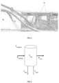
- the system measures the temperature of hot water tubes (THot) and cold-water tubes (TCold) as well as ambient temperature (TAmbient) (see figure 4 ).
- the system also records the heating power fed into the hot water cylinder, and whether the power is applied to the heating element of the cylinder or not.
- the heating element stops consuming energy after a period of time in order not to exceed the maximum temperature of the cylinder (TMax). This is the maximum energy status (EMax).
- the model can be applied by means of the following algorithms:
- TMax is the maximum heating temperature of the cylinder and corresponds to the water temperature in the cylinder when this reaches maximum energy status (EMax). The user can provide this temperature manually or it can be easily measured as the maximum Thot temperature recorded. This maximum Thot temperature recorded will occur at any time of water consumption during a maximum energy status of the hot water cylinder.
- Environmental losses of the hot water cylinder can be modelled by having two known energy statuses of the system at two separate points of time. This can be achieved by measuring the power fed into the system between two maximum energy statuses without any hot water demand between them. This is a common scenario which can also be met by controlling the heating element of the cylinder.
- Et 0 ⁇ EPLoss + EPHeating Et 1
- the temperature of the tube will reach a stable state near ambient temperature when no hot water is being consumed.
- the temperature of the outlet tube (where Thot is measured) will change following an exponential curve towards the water temperature from inside the cylinder (t1).
- the demand of hot water starts precisely at this moment (t0).
- the rate of the temperature change of the tube allows the amount of water mass being demanded (Q) to be estimated.
- the energy stored in real time is calculated as the energy present at the previous point in time, by subtracting the used energy of hot water and the losses.
- E t E t ⁇ 1 ⁇ EPloss + EPheating ⁇ Euse
- the water consumption and the user's behaviour models can be utilised to estimate future energy extractions through hot water consumption.
- Models as simple as probabilistic prediction can be applied between extractions.
- Other options include ARMA o GARCH models or adaptive neural networks.
- Reinforcement learning models can also perform this task but, in general, prediction of water consumption is closely linked to the duration of extractions. For example, there are routines requiring consumption of hot water which can be characterised. For this reason, the duration of the extraction and the time between extractions are closely linked to each other. In this case, the prediction of both parameters together may lead to better results when predicting the user's behaviour.
Landscapes
- Engineering & Computer Science (AREA)
- Physics & Mathematics (AREA)
- Thermal Sciences (AREA)
- Chemical & Material Sciences (AREA)
- Combustion & Propulsion (AREA)
- Mechanical Engineering (AREA)
- General Engineering & Computer Science (AREA)
- Computer Hardware Design (AREA)
- Heat-Pump Type And Storage Water Heaters (AREA)
- Measuring Temperature Or Quantity Of Heat (AREA)
Applications Claiming Priority (1)
| Application Number | Priority Date | Filing Date | Title |
|---|---|---|---|
| PCT/ES2020/070283 WO2021224510A1 (es) | 2020-05-05 | 2020-05-05 | Sistema controlador de cilindros de agua caliente |
Publications (2)
| Publication Number | Publication Date |
|---|---|
| EP4148508A1 true EP4148508A1 (de) | 2023-03-15 |
| EP4148508A4 EP4148508A4 (de) | 2024-01-17 |
Family
ID=78467859
Family Applications (1)
| Application Number | Title | Priority Date | Filing Date |
|---|---|---|---|
| EP20934851.5A Withdrawn EP4148508A4 (de) | 2020-05-05 | 2020-05-05 | System zur steuerung von heisswasserzylindern |
Country Status (7)
| Country | Link |
|---|---|
| US (1) | US20230073525A1 (de) |
| EP (1) | EP4148508A4 (de) |
| BR (1) | BR112022022536A2 (de) |
| CA (1) | CA3176725A1 (de) |
| CO (1) | CO2022015928A2 (de) |
| MX (1) | MX2022013754A (de) |
| WO (1) | WO2021224510A1 (de) |
Families Citing this family (1)
| Publication number | Priority date | Publication date | Assignee | Title |
|---|---|---|---|---|
| CN115183474B (zh) * | 2022-06-30 | 2023-10-13 | 广西大学 | 一种基于模型预测与深度强化学习的热水系统控制方法 |
Family Cites Families (13)
| Publication number | Priority date | Publication date | Assignee | Title |
|---|---|---|---|---|
| GB2353346A (en) * | 1999-06-23 | 2001-02-21 | Eco Therm | Control system for a water heater |
| US7346274B2 (en) * | 1999-07-27 | 2008-03-18 | Bradenbaugh Kenneth A | Water heater and method of controlling the same |
| JP2001165593A (ja) * | 1999-12-09 | 2001-06-22 | Hitachi Cable Ltd | 水温調節式熱交換器 |
| US20050235306A1 (en) * | 2002-09-23 | 2005-10-20 | Fima R G | Systems and methods for monitoring and controlling water consumption |
| IL191719A (en) * | 2008-05-26 | 2014-09-30 | Ran Amiran | Controlling the operation of an electrically heated water tank |
| CN102084190B (zh) * | 2009-04-21 | 2014-04-02 | 松下电器产业株式会社 | 储热式热水供给装置、热水供给供暖装置、运转控制装置及运转控制方法 |
| US9195242B2 (en) | 2011-04-21 | 2015-11-24 | Derek Zobrist | Energy management system and method for water heater system |
| JP5999933B2 (ja) | 2012-03-09 | 2016-09-28 | 三菱重工業株式会社 | ヒートポンプ給湯システム及びその制御方法並びにプログラム |
| CN203564100U (zh) * | 2013-11-21 | 2014-04-30 | 徐州工业职业技术学院 | 一种新型饮水机 |
| US9390381B2 (en) * | 2014-03-31 | 2016-07-12 | Shahram Davari | Intelligent water heater controller |
| EP3270350A1 (de) | 2016-07-12 | 2018-01-17 | Electricité de France | Abschätzung eines zukünftigen warmwasserverbrauchs, insbesondere zur ansteuerung eines warmwasserspeichers |
| FR3056706A1 (fr) * | 2016-09-27 | 2018-03-30 | Electricite De France | Procede d'auto-parametrage auto-adaptatif d'un systeme de chauffage et de production d'eau chaude sanitaire |
| AU2018291052B2 (en) * | 2017-06-30 | 2023-07-20 | Aquanta Inc. | Water heater usage profiling utilizing energy meter and attachable sensors |
-
2020
- 2020-05-05 EP EP20934851.5A patent/EP4148508A4/de not_active Withdrawn
- 2020-05-05 MX MX2022013754A patent/MX2022013754A/es unknown
- 2020-05-05 CA CA3176725A patent/CA3176725A1/en active Pending
- 2020-05-05 US US17/997,927 patent/US20230073525A1/en not_active Abandoned
- 2020-05-05 WO PCT/ES2020/070283 patent/WO2021224510A1/es not_active Ceased
- 2020-05-05 BR BR112022022536A patent/BR112022022536A2/pt not_active Application Discontinuation
-
2022
- 2022-11-04 CO CONC2022/0015928A patent/CO2022015928A2/es unknown
Also Published As
| Publication number | Publication date |
|---|---|
| WO2021224510A1 (es) | 2021-11-11 |
| EP4148508A4 (de) | 2024-01-17 |
| CA3176725A1 (en) | 2021-11-11 |
| MX2022013754A (es) | 2022-11-30 |
| US20230073525A1 (en) | 2023-03-09 |
| CO2022015928A2 (es) | 2023-03-27 |
| BR112022022536A2 (pt) | 2022-12-13 |
Similar Documents
| Publication | Publication Date | Title |
|---|---|---|
| US10302312B2 (en) | Estimation of unknown states for an electric water heater with thermal stratification and use of same in demand response and condition-based maintenance | |
| DK177857B1 (en) | Monitoring System | |
| GB2605469A (en) | Methods and systems and apparatus to support reduced energy usage | |
| Rogers et al. | Adaptive home heating control through Gaussian process prediction and mathematical programming | |
| Ha et al. | A home automation system to improve household energy control | |
| JP6328283B2 (ja) | コントローラ、スケジュール作成方法、及びプログラム | |
| US11085667B2 (en) | Estimation of temperature states for an electric water heater from inferred resistance measurement | |
| US11313573B2 (en) | Load management system and method utilizing occupancy data and learned device behavior | |
| Yemula | Architecture for demand responsive HVAC in a commercial building for transformer lifetime improvement | |
| EP4148508A1 (de) | System zur steuerung von heisswasserzylindern | |
| JP6553933B2 (ja) | 電力制御方法、電力制御装置、および電力制御システム | |
| JP6628831B2 (ja) | コントローラ、スケジュール作成方法、及びプログラム | |
| JP6513257B2 (ja) | コントローラ、スケジュール作成方法、及びプログラム | |
| JP6315563B2 (ja) | 設備機器運転システムおよび設備機器運転方法 | |
| CN105229893B (zh) | 管理装置、设备管理方法、管理系统 | |
| KR101423158B1 (ko) | 서브 미터링 기반 피크전력 관리 방법 및 시스템 | |
| WO2020242851A1 (en) | Estimation of temperature states for an electric water heater from inferred resistance measurement | |
| JP2019121016A (ja) | 給湯方法、及び、制御装置 | |
| KR20140086252A (ko) | 전기 에너지 절감량 측정 방법 및 이를 적용한 에너지 관리 시스템 | |
| EP3335092B1 (de) | Vorrichtung zur verwaltung von warmwasser in einen warmwasserspeicherheizsystem und zugehöriges verfahren | |
| JP6115831B2 (ja) | コントローラ、スケジュール作成方法、及びプログラム | |
| KR20180028816A (ko) | 에너지시뮬레이션모델 생성방법 및 생성장치, 그리고, 에너지시뮬레이션모델을 이용한 건물에너지관리방법 및 건물에너지관리장치 | |
| JP3970239B2 (ja) | コージェネレーションシステムの省エネルギー度演算方法 | |
| GB2519632A (en) | System And Method For Providing Electrical Supply Grid Service | |
| NL2035048B1 (en) | System and method of controlling a hot water energy storage system |
Legal Events
| Date | Code | Title | Description |
|---|---|---|---|
| STAA | Information on the status of an ep patent application or granted ep patent |
Free format text: STATUS: THE INTERNATIONAL PUBLICATION HAS BEEN MADE |
|
| PUAI | Public reference made under article 153(3) epc to a published international application that has entered the european phase |
Free format text: ORIGINAL CODE: 0009012 |
|
| STAA | Information on the status of an ep patent application or granted ep patent |
Free format text: STATUS: REQUEST FOR EXAMINATION WAS MADE |
|
| 17P | Request for examination filed |
Effective date: 20221111 |
|
| AK | Designated contracting states |
Kind code of ref document: A1 Designated state(s): AL AT BE BG CH CY CZ DE DK EE ES FI FR GB GR HR HU IE IS IT LI LT LU LV MC MK MT NL NO PL PT RO RS SE SI SK SM TR |
|
| DAV | Request for validation of the european patent (deleted) | ||
| DAX | Request for extension of the european patent (deleted) | ||
| A4 | Supplementary search report drawn up and despatched |
Effective date: 20231219 |
|
| RIC1 | Information provided on ipc code assigned before grant |
Ipc: F24H 15/219 20220101ALI20231213BHEP Ipc: F24H 15/215 20220101ALI20231213BHEP Ipc: F24H 15/156 20220101ALI20231213BHEP Ipc: F24H 15/152 20220101ALI20231213BHEP Ipc: F24H 15/148 20220101ALI20231213BHEP Ipc: F24H 15/45 20220101ALI20231213BHEP Ipc: F24H 1/50 20220101ALI20231213BHEP Ipc: F24H 9/02 20060101ALI20231213BHEP Ipc: F24D 17/00 20220101ALI20231213BHEP Ipc: F24D 19/10 20060101ALI20231213BHEP Ipc: G05B 13/02 20060101AFI20231213BHEP |
|
| STAA | Information on the status of an ep patent application or granted ep patent |
Free format text: STATUS: THE APPLICATION IS DEEMED TO BE WITHDRAWN |
|
| 18D | Application deemed to be withdrawn |
Effective date: 20240710 |