EP4148493A1 - Camera assembly - Google Patents
Camera assembly Download PDFInfo
- Publication number
- EP4148493A1 EP4148493A1 EP22189181.5A EP22189181A EP4148493A1 EP 4148493 A1 EP4148493 A1 EP 4148493A1 EP 22189181 A EP22189181 A EP 22189181A EP 4148493 A1 EP4148493 A1 EP 4148493A1
- Authority
- EP
- European Patent Office
- Prior art keywords
- window
- camera assembly
- assembly according
- sampling
- sensor
- Prior art date
- Legal status (The legal status is an assumption and is not a legal conclusion. Google has not performed a legal analysis and makes no representation as to the accuracy of the status listed.)
- Pending
Links
Images


Classifications
-
- G—PHYSICS
- G03—PHOTOGRAPHY; CINEMATOGRAPHY; ANALOGOUS TECHNIQUES USING WAVES OTHER THAN OPTICAL WAVES; ELECTROGRAPHY; HOLOGRAPHY
- G03B—APPARATUS OR ARRANGEMENTS FOR TAKING PHOTOGRAPHS OR FOR PROJECTING OR VIEWING THEM; APPARATUS OR ARRANGEMENTS EMPLOYING ANALOGOUS TECHNIQUES USING WAVES OTHER THAN OPTICAL WAVES; ACCESSORIES THEREFOR
- G03B11/00—Filters or other obturators specially adapted for photographic purposes
- G03B11/04—Hoods or caps for eliminating unwanted light from lenses, viewfinders or focusing aids
- G03B11/043—Protective lens closures or lens caps built into cameras
-
- H—ELECTRICITY
- H04—ELECTRIC COMMUNICATION TECHNIQUE
- H04N—PICTORIAL COMMUNICATION, e.g. TELEVISION
- H04N23/00—Cameras or camera modules comprising electronic image sensors; Control thereof
- H04N23/50—Constructional details
- H04N23/55—Optical parts specially adapted for electronic image sensors; Mounting thereof
-
- G—PHYSICS
- G03—PHOTOGRAPHY; CINEMATOGRAPHY; ANALOGOUS TECHNIQUES USING WAVES OTHER THAN OPTICAL WAVES; ELECTROGRAPHY; HOLOGRAPHY
- G03B—APPARATUS OR ARRANGEMENTS FOR TAKING PHOTOGRAPHS OR FOR PROJECTING OR VIEWING THEM; APPARATUS OR ARRANGEMENTS EMPLOYING ANALOGOUS TECHNIQUES USING WAVES OTHER THAN OPTICAL WAVES; ACCESSORIES THEREFOR
- G03B11/00—Filters or other obturators specially adapted for photographic purposes
- G03B11/04—Hoods or caps for eliminating unwanted light from lenses, viewfinders or focusing aids
-
- B—PERFORMING OPERATIONS; TRANSPORTING
- B60—VEHICLES IN GENERAL
- B60R—VEHICLES, VEHICLE FITTINGS, OR VEHICLE PARTS, NOT OTHERWISE PROVIDED FOR
- B60R1/00—Optical viewing arrangements; Real-time viewing arrangements for drivers or passengers using optical image capturing systems, e.g. cameras or video systems specially adapted for use in or on vehicles
- B60R1/20—Real-time viewing arrangements for drivers or passengers using optical image capturing systems, e.g. cameras or video systems specially adapted for use in or on vehicles
- B60R1/29—Real-time viewing arrangements for drivers or passengers using optical image capturing systems, e.g. cameras or video systems specially adapted for use in or on vehicles for viewing an area inside the vehicle, e.g. for viewing passengers or cargo
-
- G—PHYSICS
- G03—PHOTOGRAPHY; CINEMATOGRAPHY; ANALOGOUS TECHNIQUES USING WAVES OTHER THAN OPTICAL WAVES; ELECTROGRAPHY; HOLOGRAPHY
- G03B—APPARATUS OR ARRANGEMENTS FOR TAKING PHOTOGRAPHS OR FOR PROJECTING OR VIEWING THEM; APPARATUS OR ARRANGEMENTS EMPLOYING ANALOGOUS TECHNIQUES USING WAVES OTHER THAN OPTICAL WAVES; ACCESSORIES THEREFOR
- G03B19/00—Cameras
-
- G—PHYSICS
- G03—PHOTOGRAPHY; CINEMATOGRAPHY; ANALOGOUS TECHNIQUES USING WAVES OTHER THAN OPTICAL WAVES; ELECTROGRAPHY; HOLOGRAPHY
- G03B—APPARATUS OR ARRANGEMENTS FOR TAKING PHOTOGRAPHS OR FOR PROJECTING OR VIEWING THEM; APPARATUS OR ARRANGEMENTS EMPLOYING ANALOGOUS TECHNIQUES USING WAVES OTHER THAN OPTICAL WAVES; ACCESSORIES THEREFOR
- G03B30/00—Camera modules comprising integrated lens units and imaging units, specially adapted for being embedded in other devices, e.g. mobile phones or vehicles
-
- H—ELECTRICITY
- H04—ELECTRIC COMMUNICATION TECHNIQUE
- H04N—PICTORIAL COMMUNICATION, e.g. TELEVISION
- H04N23/00—Cameras or camera modules comprising electronic image sensors; Control thereof
-
- H—ELECTRICITY
- H04—ELECTRIC COMMUNICATION TECHNIQUE
- H04N—PICTORIAL COMMUNICATION, e.g. TELEVISION
- H04N23/00—Cameras or camera modules comprising electronic image sensors; Control thereof
- H04N23/50—Constructional details
- H04N23/51—Housings
-
- H—ELECTRICITY
- H04—ELECTRIC COMMUNICATION TECHNIQUE
- H04N—PICTORIAL COMMUNICATION, e.g. TELEVISION
- H04N25/00—Circuitry of solid-state image sensors [SSIS]; Control thereof
- H04N25/50—Control of the SSIS exposure
- H04N25/53—Control of the integration time
- H04N25/531—Control of the integration time by controlling rolling shutters in CMOS SSIS
-
- H—ELECTRICITY
- H04—ELECTRIC COMMUNICATION TECHNIQUE
- H04N—PICTORIAL COMMUNICATION, e.g. TELEVISION
- H04N7/00—Television systems
- H04N7/18—Closed-circuit television [CCTV] systems, i.e. systems in which the video signal is not broadcast
-
- G—PHYSICS
- G03—PHOTOGRAPHY; CINEMATOGRAPHY; ANALOGOUS TECHNIQUES USING WAVES OTHER THAN OPTICAL WAVES; ELECTROGRAPHY; HOLOGRAPHY
- G03B—APPARATUS OR ARRANGEMENTS FOR TAKING PHOTOGRAPHS OR FOR PROJECTING OR VIEWING THEM; APPARATUS OR ARRANGEMENTS EMPLOYING ANALOGOUS TECHNIQUES USING WAVES OTHER THAN OPTICAL WAVES; ACCESSORIES THEREFOR
- G03B9/00—Exposure-making shutters; Diaphragms
- G03B9/08—Shutters
-
- G—PHYSICS
- G03—PHOTOGRAPHY; CINEMATOGRAPHY; ANALOGOUS TECHNIQUES USING WAVES OTHER THAN OPTICAL WAVES; ELECTROGRAPHY; HOLOGRAPHY
- G03B—APPARATUS OR ARRANGEMENTS FOR TAKING PHOTOGRAPHS OR FOR PROJECTING OR VIEWING THEM; APPARATUS OR ARRANGEMENTS EMPLOYING ANALOGOUS TECHNIQUES USING WAVES OTHER THAN OPTICAL WAVES; ACCESSORIES THEREFOR
- G03B9/00—Exposure-making shutters; Diaphragms
- G03B9/58—Means for varying duration of "open" period of shutter
- G03B9/62—Means for varying duration of "open" period of shutter by varying interval of time between end of opening movement and beginning of closing movement
Definitions
- the present disclosure relates to a camera assembly.
- the present disclosure is particularly relevant to automotive camera assemblies, and interior automotive camera modules, such as driver monitoring camera units, and to camera windows for automotive cameras.
- Camera monitoring systems have become common in automotive applications and are used to monitor both the interior and exterior of the vehicle. Such systems are required to operate under a variety of conditions and consequently the performance demands on automotive cameras are high.
- light conditions within the interior of a vehicle will vary considerably between day and night time use, in different weather conditions, and depending on whether passengers have windows or a sunroof open or interior lights on.
- an interior RGB camera module is required to function effectively in a broad range of lighting conditions. Consequently, interior camera modules, such as those used for monitoring the driver's awareness, require relatively large, wide aperture lenses to maximise the received light in poorer lighting conditions.
- a problem arising from the above is that having a large, wide aperture lens means that a large camera window or front lens element is exposed on the interior of the vehicle. Not only does this compromise the vehicle's interior aesthetics, but it also potentially presents a distraction to the driver and other passengers.
- driver monitoring cameras are typically located in the vehicle's rear view mirror unit. Accordingly, the camera lens will be clearly visible within the driver's field of view. This may lead some drivers to a feeling that they are being watched constantly, increasing their anxiety, and reducing their concentration on driving tasks.
- the camera module may be seated behind a window provided in dark coloured facia of the housing of the unit in which the camera module is embedded.
- the window forms the optical front element of the camera, thereby providing a protective function as well as disguising it by integration into the surrounding panel.
- the requirement to maintain optical performance means that the window needs to be sufficiently large and optically transparent to avoid reducing light transmission. Consequently, whilst the camera may be less noticeable to a driver in low light conditions, the camera will remain clearly visible in brighter conditions.
- a camera assembly including: a sensor for sampling image data in a sampling step; a lens for focussing light onto the sensor; and a window supported in front of the lens for transmitting light therethrough; wherein the window includes a transparency changing material for varying the transmittance of light through the window in response to an input signal.
- the camera assembly is configured for increasing the transmittance of light through the window during the sampling step.
- the camera assembly further includes an input for receiving the input signal coinciding with the sampling step, and wherein the transmittance of light through the window is increased in response to the application of the input signal.
- the transparency changing material is changeable between a transparent state and an opaque state in response to the application of the input.
- the window includes a plurality of controllable regions of transparency changing material within which the transmittance of light may be varied in response to the input signal applied to the respective region.
- the plurality of controllable regions are provided as a plurality of controllable line regions.
- the senor is configured for operating in a rolling shutter mode in which an image is captured during a plurality of sampling steps, with each sampling step including sampling image data for an image line of the image; and wherein each controllable line region is associated with one or more image lines, and the controllable line regions are sequentially switched to a transparent state in synchronisation with the sampling of image data from the respective associated lines of the image.
- the transmission through the window may be dynamically adjusted to target light to the active regions of the sensor through the scanning process.
- the window includes one or more controllable regions of electrochromic material within which the transmittance of light may be varied in response to the electric field applied to the respective region.
- the senor is configured for operating in a global shutter mode in which an image is captured during a single sampling step, and wherein the window is switched to a transparent state in synchronisation with the sampling of image data during the sampling step.
- the camera assembly further includes: a controller for applying the input to the window for varying the transmittance of light therethrough.
- the controller controls the sensor and applies the input to the window for varying the transmittance of light therethrough in synchronisation with the sampling step.
- the camera assembly is an automotive camera assembly.
- the transparency changing material is an electrochromic material.
- the electrochromic material may be changeable between a transparent state and an opaque state in response to the application of the applied electric field.
- the electrochromic material in the opaque state forms a diffuser pattern for reducing transmittance of light through the window.
- the camera assembly further includes a plurality of electric field conductors for applying an electric field to the window.
- the camera assembly further includes a housing for enclosing the lens and sensor, wherein the window is located in an outer surface of the housing, and wherein the window is switchable between a disguised condition when the transparency changing material is in an opaque state and a exposed condition when the transparency changing material is in an transparent state.
- the window is provided as a front element of the lens.
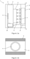
- FIG. 1a An automotive camera assembly 1 according to a first embodiment is shown in Figures 1a to 2b .
- the assembly includes a housing 2, which may form part of a larger unit or cluster within the vehicle.
- the housing 1 may be provided as part of the rear-view mirror unit mounted to interior ceiling, in front of the driver.
- a camera module 3 is secured within the housing 2 and includes a lens 4, a sensor 11, and a controller 10.
- the sensor 11 in this embodiment is a CMOS sensor which samples visible light focussed on its surface by the lens 4 and is used to generate image data through controller 10 for subsequent processing by the vehicle's safety systems.
- the lens 4 may include one or more optical elements for focussing the light onto the sensor 11.
- the controller 10 has been shown separate to the sensor 11 in the Figure, it will be understood that these components may be integrated, for instance on a common printed circuit board.
- the front of the housing 2 is provided with an aperture into which a window 6 is located, adjacent to the front of the camera lens 4.
- the camera 3 faces the exterior of the housing 2 through the window 6.
- the window 6 is thereby exposed at the front of the camera assembly, and is bordered by the adjacent surfaces of the front face 5 of the housing 2.
- the window 6 includes a transparency changing material such that the transmittance of light through the window 6 can be varied under the control of a control signal applied through input 8.
- the window is shown in its transparent state.
- the transparency changing material is an electrochromic material, although optically or thermally driven transparency changing materials may also be used. That is, in other embodiments, an optical or thermal input signal may be used to effect a change in transparency state.
- the transparency changing material may be, for example, a glass, foil, or plastic having transparency change properties.
- the input 8 is connected to the controller 10 which synchronises the output of the control signal with sampling steps performed via the sensor 11.
- the window 6 is constructed of an electrochromic material applied to a substrate, together with two electric field conductors.
- the optical properties of the window 6 can thereby be varied by applying a voltage to the electric field conductors via the input 8 for generating an electric field through the electrochromic material.
- This application of an electric field changes the state of the electrochromic material, resulting in the switching between a transparent state and an opaque state. In the opaque state, the transmittance of light through the window 6 is reduced.
- the controller 6 may apply an inversed electric field to remove the opaque colouring by transitioning the electrochromic material to the transparent or bleached state. In this state, light is transmitted though the material at its maximum intensity. Accordingly, by switching the state of the electrochromic material, the transparency of the window 6 may be varied.
- figures 1a and 1b respectively show side cross-sectional and front views of the camera assembly when in a transparent state.
- incoming light 7 may enter the assembly 1 through the window 6 and enter lens 4 for subsequent sampling by the sensor 11.
- a proportion of the incoming light 7 is reflected back as reflected light 9, which renders the optical head at the front of the lens 4 visible through the window 6 to passengers in the vehicle, as shown in Figure 1b .
- figures 2a and 2b respectively show side cross-sectional and front views of the camera assembly when in an opaque state.
- incoming light 7 is substantially absorbed by the electrochromic material within the window 6.
- the window 6 adopting a dark coloured appearance as shown in Figure 2b since incoming light 7 is absorbed and no reflected 6 light from the lens 4 is emitted.
- the window 6 is effectively blended in with the bordering front faces 5 of the housing 2.
- the sensor 11 is also prevented from receiving sufficient incoming light for optimal image generation.
- the controller 10 controls the window 6 to be in its opaque state, as shown in Figure 2b , by default.
- the lens 4 is hidden from passengers in the vehicle by the window 6.
- the camera module 3 is operated in global shutter mode in which an image frame is generated by sampling image data across the entire sensor 11 at the same point in time, in a single step.
- a video feed is generated by the controller 10 by successively repeating an image sampling step to expose the sensor 11 and thereby generate a sequence of video frames.
- the controller 10 applies a synchronisation control signal to the input 8 to switch the window 6 to its transparent state, as shown in Figure 1b , for the duration of each sampling step.
- the transparency of window 6 is thereby increased while each image is being sampled, thereby maximising the incoming light 7 entering the lens 4, and hence improving the image quality.
- the window 6 reverts to its opaque state under the control of controller 10.
- the duration of each sampling step or exposure is very brief (e.g., 5-20 milliseconds)
- the presence of the front of the lens 4 is substantially imperceptible to passengers of the vehicle. This is because the period when the window 6 is its transparent state for facilitating image capture is similarly brief. Consequently, to a passenger in the vehicle, the periods of switching to the transparent state are sufficiently short that the interior of the housing 2 appears obscured by the window 6. Nevertheless, for the generation of image data by the camera module 3 itself, incoming light 7 is permitted to pass through the window, and hence sensor operations of the camera module 3 are unaffected.
- Embodiments may also be implemented where the camera module is operating in a rolling shutter mode in which images are sampled by recording an image frame line-by-line on the image sensor 11, rather than capturing the entire frame at once.
- a flickering effect may potentially arise because the overall exposure duration is longer.
- a plurality of independently switchable areas may be provided in the window 6 such that the proportion of window 6 switched into a transparent state at any one time is limited to areas associated with the lines being sampled at that time.
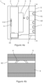
- Figures 3a-4b show a second embodiment which has a camera module 3 operating in a vertical, rolling shutter mode.
- This embodiment is substantially the same as the embodiment described in Figure 1a , except that the window 6 is provided with an array of horizontal switchable areas which may be independently switched between their opaque and transparent states.
- the control signal applied to the input 8 by controller 10 can therefore switch lines of the window 6 to allow a strip of light through for illuminating one or more associated lines of the frame on the sensor 11.
- the controller 10 again controls the window 6 to be in its opaque state by default.
- the camera module 3 operating in a rolling shutter mode, will sample image data line by line, scanning vertically down from the top of the sensor 11. Accordingly, the image frame is generated from series of sampling steps, with each step sampling a line until image data for the entire sensor 11 has been sampled. The sequence then repeats for the next image frame.
- Figures 3a and 3b show the camera assembly of the second embodiment during a first set of sampling steps in which image data is sampled from a first set of lines 111 at the top of the sensor 11.
- the controller 10 applies a control signal to the input 8 to switch the first switchable area 61 of the window 6 to its transparent state, as shown in Figure 3b , for the duration of each of the first set of sampling steps.
- the transparency of window 6 in the first region 61 is increased to apply light to the first set of lines 111 on the sensor during the sampling steps associated with that set of lines 111 of the sensor.
- the controller 10 begins sampling a second set of lines 112, as shown in Figures 4a and 4b .
- the controller 10 applies the control signal to the input 8 to switch the second switchable area 62 of the window 6 to its transparent state, as shown in Figure 4b , for the duration of each of the second set of sampling steps.
- the transparency of window 6 in the second region 62 is therefore increased to apply light to the second set of lines 112 on the sensor 11 during the sampling steps associated with that set of lines.
- the interior of the housing 2 appears obscured by the window 6. That is, although the switchable regions of the window 6 are made sequentially transparent, the periods of switching are sufficiently short, and the size of the areas are sufficiently small, that their switching is imperceptible to the passengers. Accordingly, the camera module 3 may operate normally to generate a video feed, whilst being effectively hidden behind the window 6.
- Embodiments therefore help to integrate the camera assembly 1 within the interior car styling, without impacting the aesthetics, compromising the user experience, or reducing the camera system performance.
- controller is described as being integrated into the camera assembly, in other embodiments it may be separate.
- a simplified embodiment may be provided where the camera may be obscured by the window when not in use, and then the window may be switched to a transparent state when the camera is activated and then maintained in that state while the camera remains active.
- a vehicle reversing camera may be hidden behind a window and exposed when the vehicle is put into reverse. This may allow the camera unit to blend in more discretely with the rear of the vehicle.
Landscapes
- Engineering & Computer Science (AREA)
- Multimedia (AREA)
- Signal Processing (AREA)
- Physics & Mathematics (AREA)
- General Physics & Mathematics (AREA)
- Mechanical Engineering (AREA)
- Studio Devices (AREA)
- Electrochromic Elements, Electrophoresis, Or Variable Reflection Or Absorption Elements (AREA)
Abstract
Description
- The present disclosure relates to a camera assembly. The present disclosure is particularly relevant to automotive camera assemblies, and interior automotive camera modules, such as driver monitoring camera units, and to camera windows for automotive cameras.
- Camera monitoring systems have become common in automotive applications and are used to monitor both the interior and exterior of the vehicle. Such systems are required to operate under a variety of conditions and consequently the performance demands on automotive cameras are high. As one example, light conditions within the interior of a vehicle will vary considerably between day and night time use, in different weather conditions, and depending on whether passengers have windows or a sunroof open or interior lights on. As such, an interior RGB camera module is required to function effectively in a broad range of lighting conditions. Consequently, interior camera modules, such as those used for monitoring the driver's awareness, require relatively large, wide aperture lenses to maximise the received light in poorer lighting conditions.
- A problem arising from the above is that having a large, wide aperture lens means that a large camera window or front lens element is exposed on the interior of the vehicle. Not only does this compromise the vehicle's interior aesthetics, but it also potentially presents a distraction to the driver and other passengers. For example, driver monitoring cameras are typically located in the vehicle's rear view mirror unit. Accordingly, the camera lens will be clearly visible within the driver's field of view. This may lead some drivers to a feeling that they are being watched constantly, increasing their anxiety, and reducing their concentration on driving tasks.
- Car designers will often try to mitigate the above issue by disguising the camera module within the body of other units. For example, the camera module may be seated behind a window provided in dark coloured facia of the housing of the unit in which the camera module is embedded. As such, the window forms the optical front element of the camera, thereby providing a protective function as well as disguising it by integration into the surrounding panel. Nevertheless, the requirement to maintain optical performance means that the window needs to be sufficiently large and optically transparent to avoid reducing light transmission. Consequently, whilst the camera may be less noticeable to a driver in low light conditions, the camera will remain clearly visible in brighter conditions.
- There is therefore a need to address the above problems with prior art camera assemblies.
- According to a first aspect, there is provided a camera assembly, including: a sensor for sampling image data in a sampling step; a lens for focussing light onto the sensor; and a window supported in front of the lens for transmitting light therethrough; wherein the window includes a transparency changing material for varying the transmittance of light through the window in response to an input signal.
- In embodiments, the camera assembly is configured for increasing the transmittance of light through the window during the sampling step.
- In embodiments, the camera assembly further includes an input for receiving the input signal coinciding with the sampling step, and wherein the transmittance of light through the window is increased in response to the application of the input signal.
- In embodiments, the transparency changing material is changeable between a transparent state and an opaque state in response to the application of the input.
- In embodiments, the window includes a plurality of controllable regions of transparency changing material within which the transmittance of light may be varied in response to the input signal applied to the respective region.
- In embodiments, the plurality of controllable regions are provided as a plurality of controllable line regions.
- In embodiments, the sensor is configured for operating in a rolling shutter mode in which an image is captured during a plurality of sampling steps, with each sampling step including sampling image data for an image line of the image; and wherein each controllable line region is associated with one or more image lines, and the controllable line regions are sequentially switched to a transparent state in synchronisation with the sampling of image data from the respective associated lines of the image. In this way, the transmission through the window may be dynamically adjusted to target light to the active regions of the sensor through the scanning process.
- In embodiments, the window includes one or more controllable regions of electrochromic material within which the transmittance of light may be varied in response to the electric field applied to the respective region.
- In embodiments, the sensor is configured for operating in a global shutter mode in which an image is captured during a single sampling step, and wherein the window is switched to a transparent state in synchronisation with the sampling of image data during the sampling step.
- In embodiments, the camera assembly further includes: a controller for applying the input to the window for varying the transmittance of light therethrough.
- In embodiments, the controller controls the sensor and applies the input to the window for varying the transmittance of light therethrough in synchronisation with the sampling step.
- In embodiments, the camera assembly is an automotive camera assembly.
- In embodiments, the transparency changing material is an electrochromic material. As such, the electrochromic material may be changeable between a transparent state and an opaque state in response to the application of the applied electric field. In embodiments, the electrochromic material in the opaque state forms a diffuser pattern for reducing transmittance of light through the window.
- In embodiments, the camera assembly further includes a plurality of electric field conductors for applying an electric field to the window.
- In embodiments, the camera assembly further includes a housing for enclosing the lens and sensor, wherein the window is located in an outer surface of the housing, and wherein the window is switchable between a disguised condition when the transparency changing material is in an opaque state and a exposed condition when the transparency changing material is in an transparent state.
- In embodiments, the window is provided as a front element of the lens.
- Illustrative embodiments will now be described with reference to the accompanying drawings in which:
-
Figure 1a is a schematic cross-sectional view of a camera assembly according to a first embodiment when in a transparent state; -
Figure 1b is a front view of the camera assembly of the first embodiment, when in the transparent state; -
Figure 2a is a schematic cross-sectional view of the camera assembly of the first embodiment when in an opaque state; -
Figure 2b is a front view of the camera assembly of the first embodiment when in the opaque state; -
Figure 3a is a schematic cross-sectional view of a camera assembly according to a second embodiment during a first set of sampling steps; -
Figure 3b is a front view of the camera assembly of the second embodiment during the first set of sampling steps; -
Figure 4a is a schematic cross-sectional view of a camera assembly of the second embodiment during a second set of sampling steps; and -
Figure 4b is a front view of the camera assembly of the second embodiment during the second set of sampling step. - An
automotive camera assembly 1 according to a first embodiment is shown inFigures 1a to 2b . Starting initially withFigure 1a , the assembly includes ahousing 2, which may form part of a larger unit or cluster within the vehicle. For example, in the case of a driver awareness camera system, thehousing 1 may be provided as part of the rear-view mirror unit mounted to interior ceiling, in front of the driver. - A
camera module 3 is secured within thehousing 2 and includes alens 4, asensor 11, and acontroller 10. Thesensor 11 in this embodiment is a CMOS sensor which samples visible light focussed on its surface by thelens 4 and is used to generate image data throughcontroller 10 for subsequent processing by the vehicle's safety systems. It will be understood that thelens 4 may include one or more optical elements for focussing the light onto thesensor 11. Furthermore, although thecontroller 10 has been shown separate to thesensor 11 in the Figure, it will be understood that these components may be integrated, for instance on a common printed circuit board. - As shown in
Figure 1a , the front of thehousing 2 is provided with an aperture into which awindow 6 is located, adjacent to the front of thecamera lens 4. As such, thecamera 3 faces the exterior of thehousing 2 through thewindow 6. As shown inFigure 1b , thewindow 6 is thereby exposed at the front of the camera assembly, and is bordered by the adjacent surfaces of thefront face 5 of thehousing 2. - The
window 6 includes a transparency changing material such that the transmittance of light through thewindow 6 can be varied under the control of a control signal applied throughinput 8. InFigures 1a and 1b , the window is shown in its transparent state. In this embodiment, the transparency changing material is an electrochromic material, although optically or thermally driven transparency changing materials may also be used. That is, in other embodiments, an optical or thermal input signal may be used to effect a change in transparency state. The transparency changing material may be, for example, a glass, foil, or plastic having transparency change properties. Theinput 8 is connected to thecontroller 10 which synchronises the output of the control signal with sampling steps performed via thesensor 11. - In this embodiment, the
window 6 is constructed of an electrochromic material applied to a substrate, together with two electric field conductors. In use, the optical properties of thewindow 6 can thereby be varied by applying a voltage to the electric field conductors via theinput 8 for generating an electric field through the electrochromic material. This application of an electric field changes the state of the electrochromic material, resulting in the switching between a transparent state and an opaque state. In the opaque state, the transmittance of light through thewindow 6 is reduced. Conversely, thecontroller 6 may apply an inversed electric field to remove the opaque colouring by transitioning the electrochromic material to the transparent or bleached state. In this state, light is transmitted though the material at its maximum intensity. Accordingly, by switching the state of the electrochromic material, the transparency of thewindow 6 may be varied. - As mentioned above,
figures 1a and 1b respectively show side cross-sectional and front views of the camera assembly when in a transparent state. As such,incoming light 7 may enter theassembly 1 through thewindow 6 and enterlens 4 for subsequent sampling by thesensor 11. At the same time, a proportion of theincoming light 7 is reflected back as reflectedlight 9, which renders the optical head at the front of thelens 4 visible through thewindow 6 to passengers in the vehicle, as shown inFigure 1b . - Conversely,
figures 2a and 2b respectively show side cross-sectional and front views of the camera assembly when in an opaque state. In this case,incoming light 7 is substantially absorbed by the electrochromic material within thewindow 6. This results in thewindow 6 adopting a dark coloured appearance as shown inFigure 2b sinceincoming light 7 is absorbed and no reflected 6 light from thelens 4 is emitted. Accordingly, thewindow 6 is effectively blended in with the bordering front faces 5 of thehousing 2. However, in the opaque state, thesensor 11 is also prevented from receiving sufficient incoming light for optimal image generation. - In use, the
controller 10 controls thewindow 6 to be in its opaque state, as shown inFigure 2b , by default. As such, thelens 4 is hidden from passengers in the vehicle by thewindow 6. In this first embodiment, thecamera module 3 is operated in global shutter mode in which an image frame is generated by sampling image data across theentire sensor 11 at the same point in time, in a single step. As such, when thecamera module 3 is activated, a video feed is generated by thecontroller 10 by successively repeating an image sampling step to expose thesensor 11 and thereby generate a sequence of video frames. At the same time, thecontroller 10 applies a synchronisation control signal to theinput 8 to switch thewindow 6 to its transparent state, as shown inFigure 1b , for the duration of each sampling step. The transparency ofwindow 6 is thereby increased while each image is being sampled, thereby maximising theincoming light 7 entering thelens 4, and hence improving the image quality. Once the image data has been sampled, thewindow 6 reverts to its opaque state under the control ofcontroller 10. - As the duration of each sampling step or exposure is very brief (e.g., 5-20 milliseconds), the presence of the front of the
lens 4 is substantially imperceptible to passengers of the vehicle. This is because the period when thewindow 6 is its transparent state for facilitating image capture is similarly brief. Consequently, to a passenger in the vehicle, the periods of switching to the transparent state are sufficiently short that the interior of thehousing 2 appears obscured by thewindow 6. Nevertheless, for the generation of image data by thecamera module 3 itself,incoming light 7 is permitted to pass through the window, and hence sensor operations of thecamera module 3 are unaffected. - Embodiments may also be implemented where the camera module is operating in a rolling shutter mode in which images are sampled by recording an image frame line-by-line on the
image sensor 11, rather than capturing the entire frame at once. In such an arrangement, if the entirety of thewindow 6 were switched to a transparent state for the duration of time where light is being sampled by thesensor 11, a flickering effect may potentially arise because the overall exposure duration is longer. To address this, a plurality of independently switchable areas may be provided in thewindow 6 such that the proportion ofwindow 6 switched into a transparent state at any one time is limited to areas associated with the lines being sampled at that time. - In this connection,
Figures 3a-4b show a second embodiment which has acamera module 3 operating in a vertical, rolling shutter mode. This embodiment is substantially the same as the embodiment described inFigure 1a , except that thewindow 6 is provided with an array of horizontal switchable areas which may be independently switched between their opaque and transparent states. The control signal applied to theinput 8 bycontroller 10 can therefore switch lines of thewindow 6 to allow a strip of light through for illuminating one or more associated lines of the frame on thesensor 11. - In use, the
controller 10 again controls thewindow 6 to be in its opaque state by default. Thecamera module 3, operating in a rolling shutter mode, will sample image data line by line, scanning vertically down from the top of thesensor 11. Accordingly, the image frame is generated from series of sampling steps, with each step sampling a line until image data for theentire sensor 11 has been sampled. The sequence then repeats for the next image frame. - Following the above,
Figures 3a and 3b show the camera assembly of the second embodiment during a first set of sampling steps in which image data is sampled from a first set oflines 111 at the top of thesensor 11. At the same time, thecontroller 10 applies a control signal to theinput 8 to switch the firstswitchable area 61 of thewindow 6 to its transparent state, as shown inFigure 3b , for the duration of each of the first set of sampling steps. As such, the transparency ofwindow 6 in thefirst region 61 is increased to apply light to the first set oflines 111 on the sensor during the sampling steps associated with that set oflines 111 of the sensor. - Once the sampling steps for the first set of
lines 111 have been completed, thecontroller 10 begins sampling a second set oflines 112, as shown inFigures 4a and 4b . During these later sampling steps, thecontroller 10 applies the control signal to theinput 8 to switch the secondswitchable area 62 of thewindow 6 to its transparent state, as shown inFigure 4b , for the duration of each of the second set of sampling steps. The transparency ofwindow 6 in thesecond region 62 is therefore increased to apply light to the second set oflines 112 on thesensor 11 during the sampling steps associated with that set of lines. - The above process proceeds for the remaining sets of lines of the
sensor 11 and associated switchable areas of thewindow 6 until the entire frame has been sampled. The process then repeats for further frames. - As with the first embodiment, to a passenger in the vehicle, the interior of the
housing 2 appears obscured by thewindow 6. That is, although the switchable regions of thewindow 6 are made sequentially transparent, the periods of switching are sufficiently short, and the size of the areas are sufficiently small, that their switching is imperceptible to the passengers. Accordingly, thecamera module 3 may operate normally to generate a video feed, whilst being effectively hidden behind thewindow 6. - Embodiments therefore help to integrate the
camera assembly 1 within the interior car styling, without impacting the aesthetics, compromising the user experience, or reducing the camera system performance. - It will be understood that the embodiments illustrated above show applications only for the purposes of illustration. In practice, embodiments may be applied to many different configurations, the detailed embodiments being straightforward for those skilled in the art to implement.
- For example, it will be understood that although in the above embodiments the controller is described as being integrated into the camera assembly, in other embodiments it may be separate.
- Furthermore, although a vertical rolling shutter operation has been described in conjunction with horizontal switchable areas of the window, it will be understood that embodiments may be applied to camera modules operating using a horizontal rolling shutter. In such embodiments, the lines of switchable areas may be provided vertically.
- Moreover, although the above examples concern automotive camera systems used for sustained operations, such as driver awareness camera systems, it will be understood that embodiments may be provided for where the camera is used only intermittently. For example, a simplified embodiment may be provided where the camera may be obscured by the window when not in use, and then the window may be switched to a transparent state when the camera is activated and then maintained in that state while the camera remains active. For example, a vehicle reversing camera may be hidden behind a window and exposed when the vehicle is put into reverse. This may allow the camera unit to blend in more discretely with the rear of the vehicle.
Claims (15)
- A camera assembly, comprising:a sensor for sampling image data in a sampling step;a lens for focussing light onto the sensor; anda window supported in front of the lens for transmitting light therethrough;wherein the window comprises a transparency changing material for varying the transmittance of light through the window in response to an input signal.
- The camera assembly according to claim 1, wherein the camera assembly is configured for increasing the transmittance of light through the window during the sampling step.
- The camera assembly according to claim 2, further comprising an input for receiving the input signal coinciding with the sampling step, and wherein the transmittance of light through the window is increased in response to the application of the input signal.
- The camera assembly according to any preceding claim, the transparency changing material is changeable between a transparent state and an opaque state in response to the application of the input.
- The camera assembly according to any preceding claim, wherein the window comprises a plurality of controllable regions of transparency changing material within which the transmittance of light may be varied in response to the input signal applied to the respective region.
- The camera assembly according to claim 5, wherein the plurality of controllable regions are provided as a plurality of controllable line regions.
- The camera assembly according to any of claim 6, wherein the sensor is configured for operating in a rolling shutter mode in which an image is captured during a plurality of sampling steps, with each sampling step comprising sampling image data for an image line of the image; and
wherein each controllable line region is associated with one or more image lines, and the controllable line regions are sequentially switched to a transparent state in synchronisation with the sampling of image data from the respective associated lines of the image. - The camera assembly according to any of claims 1-5, wherein the sensor is configured for operating in a global shutter mode in which an image is captured during a single sampling step, and
wherein the window is switched to a transparent state in synchronisation with the sampling of image data during the sampling step. - The camera assembly according to any preceding claim, further comprising:
a controller for applying the input to the window for varying the transmittance of light therethrough. - The camera assembly according to claim 9, wherein the controller controls the sensor and applies the input to the window for varying the transmittance of light therethrough in synchronisation with the sampling step.
- The camera assembly according to any preceding claim, wherein the camera assembly is an automotive camera assembly.
- The camera assembly according to any preceding claim, wherein the transparency changing material is an electrochromic material.
- The camera assembly according to claim 11, further comprising a plurality of electric field conductors for applying an electric field to the window.
- The camera assembly according to any preceding claim, further comprising a housing for enclosing the lens and sensor, wherein the window is located in an outer surface of the housing, and wherein the window is switchable between a disguised condition when the transparency changing material is in an opaque state and a exposed condition when the transparency changing material is in an transparent state.
- The camera assembly according to any preceding claim, wherein the window is provided as a front element of the lens.
Applications Claiming Priority (1)
| Application Number | Priority Date | Filing Date | Title |
|---|---|---|---|
| GB2112870.7A GB2611285A (en) | 2021-09-09 | 2021-09-09 | Camera assembly |
Publications (1)
| Publication Number | Publication Date |
|---|---|
| EP4148493A1 true EP4148493A1 (en) | 2023-03-15 |
Family
ID=78149254
Family Applications (1)
| Application Number | Title | Priority Date | Filing Date |
|---|---|---|---|
| EP22189181.5A Pending EP4148493A1 (en) | 2021-09-09 | 2022-08-08 | Camera assembly |
Country Status (4)
| Country | Link |
|---|---|
| US (1) | US11696010B2 (en) |
| EP (1) | EP4148493A1 (en) |
| CN (1) | CN115802136B (en) |
| GB (1) | GB2611285A (en) |
Citations (3)
| Publication number | Priority date | Publication date | Assignee | Title |
|---|---|---|---|---|
| US20140300805A1 (en) * | 2013-04-05 | 2014-10-09 | Red.Com, Inc. | Optical filtering for cameras |
| WO2017075459A1 (en) * | 2015-10-30 | 2017-05-04 | Essential Products, Inc. | Optical sensors disposed beneath the display of an electronic device |
| US20190346742A1 (en) * | 2018-05-09 | 2019-11-14 | Gentex Corporation | Switchable imager lens cover |
Family Cites Families (15)
| Publication number | Priority date | Publication date | Assignee | Title |
|---|---|---|---|---|
| JP2919631B2 (en) * | 1991-04-23 | 1999-07-12 | シャープ株式会社 | Display camera device |
| EP2328330B1 (en) * | 2009-11-25 | 2011-08-10 | Research In Motion Limited | Systems and methods for covering a component on an electronic device |
| AU2011220382A1 (en) * | 2010-02-28 | 2012-10-18 | Microsoft Corporation | Local advertising content on an interactive head-mounted eyepiece |
| JP2012098322A (en) * | 2010-10-29 | 2012-05-24 | Sony Corp | Imaging apparatus |
| JP2015166338A (en) * | 2014-02-12 | 2015-09-24 | キヤノン株式会社 | Organic compound and electrochromic device using the same |
| US10509298B2 (en) * | 2016-08-23 | 2019-12-17 | Roo, Inc. | Optical device with electrochromic lens cap |
| US10180615B2 (en) * | 2016-10-31 | 2019-01-15 | Google Llc | Electrochromic filtering in a camera |
| CN107426560A (en) * | 2017-06-22 | 2017-12-01 | 维沃移动通信有限公司 | A kind of filming apparatus, image processing method and mobile terminal |
| WO2019010687A1 (en) * | 2017-07-14 | 2019-01-17 | Applied Materials, Inc. | Electrically controllable optical device, method for operation thereof, and system including an electrically controllable optical device |
| CN108989635A (en) * | 2018-07-18 | 2018-12-11 | 夏培准 | Monitoring camera |
| CN109286704B (en) * | 2018-09-30 | 2021-06-15 | 联想(北京)有限公司 | Electronic device |
| CN110646995A (en) * | 2019-09-25 | 2020-01-03 | Oppo(重庆)智能科技有限公司 | Lens assembly, periscopic camera and electronic equipment |
| US11816905B2 (en) * | 2020-03-19 | 2023-11-14 | Magna Electronics Inc. | Multi-camera vision system integrated into interior rearview mirror |
| CN111694198B (en) * | 2020-06-01 | 2023-04-18 | Oppo广东移动通信有限公司 | Electrochromic controller, method and device and electronic equipment |
| CN113130607B (en) * | 2021-04-02 | 2023-08-25 | 维沃移动通信有限公司 | Display device, electronic apparatus, control method, device, and readable storage medium |
-
2021
- 2021-09-09 GB GB2112870.7A patent/GB2611285A/en active Pending
-
2022
- 2022-08-08 EP EP22189181.5A patent/EP4148493A1/en active Pending
- 2022-08-08 CN CN202210942467.2A patent/CN115802136B/en active Active
- 2022-09-09 US US17/930,929 patent/US11696010B2/en active Active
Patent Citations (3)
| Publication number | Priority date | Publication date | Assignee | Title |
|---|---|---|---|---|
| US20140300805A1 (en) * | 2013-04-05 | 2014-10-09 | Red.Com, Inc. | Optical filtering for cameras |
| WO2017075459A1 (en) * | 2015-10-30 | 2017-05-04 | Essential Products, Inc. | Optical sensors disposed beneath the display of an electronic device |
| US20190346742A1 (en) * | 2018-05-09 | 2019-11-14 | Gentex Corporation | Switchable imager lens cover |
Also Published As
| Publication number | Publication date |
|---|---|
| CN115802136A (en) | 2023-03-14 |
| GB202112870D0 (en) | 2021-10-27 |
| US20230070854A1 (en) | 2023-03-09 |
| US11696010B2 (en) | 2023-07-04 |
| CN115802136B (en) | 2023-08-15 |
| GB2611285A (en) | 2023-04-05 |
Similar Documents
| Publication | Publication Date | Title |
|---|---|---|
| US12240384B2 (en) | Interior rearview mirror assembly with full screen video display | |
| KR101011507B1 (en) | Vehicle rearview mirror assembly with high intensity display | |
| US7683326B2 (en) | Vehicle vision system with high dynamic range | |
| US10562378B2 (en) | Shading device for vehicle | |
| US20090096937A1 (en) | Vehicle Rearview Assembly Including a Display for Displaying Video Captured by a Camera and User Instructions | |
| WO2020100674A1 (en) | Display device | |
| EP4219238B1 (en) | Rear-view mirror system | |
| US11696010B2 (en) | Camera assembly | |
| JP3027979B2 (en) | Optoelectronic filters for vehicle cameras | |
| US20200226975A1 (en) | Blind spot reduction system | |
| CN223720620U (en) | Dimming system of window glass and vehicle | |
| EP4177094B1 (en) | Display system | |
| JP2003127771A (en) | In-vehicle camera with auxiliary lighting | |
| KR20010069929A (en) | Display device for driving information | |
| EP4173869A1 (en) | Display device and display system | |
| EP4112355A1 (en) | Method and system for operating a display device, specially in a motor vehicle | |
| KR200193225Y1 (en) | Apparatus for observing the rear of a car using the plural ccd cameras | |
| JP3468622B2 (en) | Vehicle view device | |
| CN1541866A (en) | Rearview mirror capable of eliminating emergency light reflex effect on eyes in realtime | |
| JPH07329637A (en) | Vehicle exterior monitor |
Legal Events
| Date | Code | Title | Description |
|---|---|---|---|
| PUAI | Public reference made under article 153(3) epc to a published international application that has entered the european phase |
Free format text: ORIGINAL CODE: 0009012 |
|
| STAA | Information on the status of an ep patent application or granted ep patent |
Free format text: STATUS: THE APPLICATION HAS BEEN PUBLISHED |
|
| AK | Designated contracting states |
Kind code of ref document: A1 Designated state(s): AL AT BE BG CH CY CZ DE DK EE ES FI FR GB GR HR HU IE IS IT LI LT LU LV MC MK MT NL NO PL PT RO RS SE SI SK SM TR |
|
| STAA | Information on the status of an ep patent application or granted ep patent |
Free format text: STATUS: REQUEST FOR EXAMINATION WAS MADE |
|
| 17P | Request for examination filed |
Effective date: 20230718 |
|
| RBV | Designated contracting states (corrected) |
Designated state(s): AL AT BE BG CH CY CZ DE DK EE ES FI FR GB GR HR HU IE IS IT LI LT LU LV MC MK MT NL NO PL PT RO RS SE SI SK SM TR |
|
| RAP1 | Party data changed (applicant data changed or rights of an application transferred) |
Owner name: APTIV TECHNOLOGIES AG |
|
| RAP3 | Party data changed (applicant data changed or rights of an application transferred) |
Owner name: APTIV TECHNOLOGIES AG |
|
| STAA | Information on the status of an ep patent application or granted ep patent |
Free format text: STATUS: EXAMINATION IS IN PROGRESS |
|
| 17Q | First examination report despatched |
Effective date: 20250521 |