EP4148409A1 - Wheel test device - Google Patents
Wheel test device Download PDFInfo
- Publication number
- EP4148409A1 EP4148409A1 EP21800567.6A EP21800567A EP4148409A1 EP 4148409 A1 EP4148409 A1 EP 4148409A1 EP 21800567 A EP21800567 A EP 21800567A EP 4148409 A1 EP4148409 A1 EP 4148409A1
- Authority
- EP
- European Patent Office
- Prior art keywords
- wheel
- test
- electric motor
- rail
- torque
- Prior art date
- Legal status (The legal status is an assumption and is not a legal conclusion. Google has not performed a legal analysis and makes no representation as to the accuracy of the status listed.)
- Pending
Links
- 238000012360 testing method Methods 0.000 title claims abstract description 195
- 230000002093 peripheral effect Effects 0.000 claims description 16
- 238000005259 measurement Methods 0.000 claims description 9
- 230000005540 biological transmission Effects 0.000 description 46
- 230000007246 mechanism Effects 0.000 description 27
- 238000001514 detection method Methods 0.000 description 11
- 238000006243 chemical reaction Methods 0.000 description 10
- 239000003638 chemical reducing agent Substances 0.000 description 10
- 239000008186 active pharmaceutical agent Substances 0.000 description 5
- 230000008878 coupling Effects 0.000 description 5
- 238000010168 coupling process Methods 0.000 description 5
- 238000005859 coupling reaction Methods 0.000 description 5
- 238000005096 rolling process Methods 0.000 description 5
- 230000008859 change Effects 0.000 description 4
- 238000010586 diagram Methods 0.000 description 4
- 238000004804 winding Methods 0.000 description 4
- 239000000835 fiber Substances 0.000 description 3
- 230000003993 interaction Effects 0.000 description 3
- 238000010998 test method Methods 0.000 description 3
- 229920000049 Carbon (fiber) Polymers 0.000 description 2
- 230000001133 acceleration Effects 0.000 description 2
- 239000004917 carbon fiber Substances 0.000 description 2
- 238000005265 energy consumption Methods 0.000 description 2
- VNWKTOKETHGBQD-UHFFFAOYSA-N methane Chemical compound C VNWKTOKETHGBQD-UHFFFAOYSA-N 0.000 description 2
- OKTJSMMVPCPJKN-UHFFFAOYSA-N Carbon Chemical group [C] OKTJSMMVPCPJKN-UHFFFAOYSA-N 0.000 description 1
- 229910000831 Steel Inorganic materials 0.000 description 1
- 239000004699 Ultra-high molecular weight polyethylene Substances 0.000 description 1
- 239000000853 adhesive Substances 0.000 description 1
- 230000001070 adhesive effect Effects 0.000 description 1
- 229920006231 aramid fiber Polymers 0.000 description 1
- 238000005452 bending Methods 0.000 description 1
- 238000009530 blood pressure measurement Methods 0.000 description 1
- 238000004891 communication Methods 0.000 description 1
- 239000004973 liquid crystal related substance Substances 0.000 description 1
- 238000000034 method Methods 0.000 description 1
- 238000012986 modification Methods 0.000 description 1
- 230000004048 modification Effects 0.000 description 1
- 230000003287 optical effect Effects 0.000 description 1
- 230000000149 penetrating effect Effects 0.000 description 1
- 238000003825 pressing Methods 0.000 description 1
- 230000003068 static effect Effects 0.000 description 1
- 239000010959 steel Substances 0.000 description 1
- 229920000785 ultra high molecular weight polyethylene Polymers 0.000 description 1
Images


Classifications
-
- G—PHYSICS
- G01—MEASURING; TESTING
- G01M—TESTING STATIC OR DYNAMIC BALANCE OF MACHINES OR STRUCTURES; TESTING OF STRUCTURES OR APPARATUS, NOT OTHERWISE PROVIDED FOR
- G01M17/00—Testing of vehicles
- G01M17/08—Railway vehicles
- G01M17/10—Suspensions, axles or wheels
-
- G—PHYSICS
- G01—MEASURING; TESTING
- G01M—TESTING STATIC OR DYNAMIC BALANCE OF MACHINES OR STRUCTURES; TESTING OF STRUCTURES OR APPARATUS, NOT OTHERWISE PROVIDED FOR
- G01M99/00—Subject matter not provided for in other groups of this subclass
- G01M99/004—Testing the effects of speed or acceleration
-
- G—PHYSICS
- G01—MEASURING; TESTING
- G01M—TESTING STATIC OR DYNAMIC BALANCE OF MACHINES OR STRUCTURES; TESTING OF STRUCTURES OR APPARATUS, NOT OTHERWISE PROVIDED FOR
- G01M99/00—Subject matter not provided for in other groups of this subclass
- G01M99/007—Subject matter not provided for in other groups of this subclass by applying a load, e.g. for resistance or wear testing
Definitions
- the present invention relates to a wheel test device.
- Patent Document 1 discloses a test device capable of performing a test simulating a running state of a railway vehicle by rotating both a rail wheel which is a disk-shaped member having a cross-sectional shape simulating a rail at an outer peripheral portion thereof and a wheel in a state where the wheel is pressed against the rail wheel.
- test device disclosed in Patent Document 1 is driven by a single electric motor, when performing a test for applying a large torque to the wheel while rotating the wheel at a high speed, it is necessary to use a large-capacity electric motor, and thus there is a problem that power consumption during the test becomes enormous.
- the present invention has been made in view of the foregoing circumstances, and it is an object of the present invention to reduce power consumption of a wheel test device.
- a wheel test device including a rail wheel support unit configured to rotatably support a rail wheel, a wheel support unit configured to rotatably support a test wheel in a state where the test wheel is in contact with the rail wheel, a first electric motor configured to rotate the rail wheel and the test wheel, and a torque generating device configured to generate torque to be applied to the test wheel, the torque generating device including a rotating frame rotationally driven by the first electric motor, and a second electric motor mounted on the rotating frame, and at least one of the rail wheel and the test wheel being connected to the first electric motor via the torque generating device.
- the above-described wheel test device may include power distributing means configured to distribute power generated by the first electric motor to the rail wheel and the test wheel.
- the rail wheel and the test wheel may be configured to rotate in opposite directions at substantially the same peripheral speed when the operation of the second electric motor is stopped.
- the torque generating device may include an output shaft disposed coaxially with the rotating frame.
- the torque generating device may include a bearing unit configured to rotatably support the rotating frame, the rotating frame may have a cylindrical shaft part supported by the bearing unit, a bearing may be provided on an inner periphery of the shaft part; and the output shaft may pass through a hollow portion of the shaft part and may be rotatably supported by the bearing.
- the first electric motor may be disposed coaxially with the rotating frame.
- the second electric motor may be fixed to the rotating frame via a plurality of rod-shaped connecting members arranged radially about a rotation axis of the rotating frame.
- the rotating frame may include a cylindrical motor housing part configured to house the second electric motor.
- the above-described wheel test device may include a control part configured to control the first electric motor and the second electric motor, a rotation speed measuring means configured to measure a rotation speed of the rail wheel, and a torque measuring means configured to measure the torque of the test wheel, and the control part may control driving of the first electric motor based on measurement result of the rotation speed measuring means, and may control driving of the second electric motor based on measurement result of the torque measuring means.
- the above-described wheel test device may include a wheel load applying unit configured to apply a wheel load to the test wheel by moving one of the test wheel and the rail wheel forward and backward with respect to the other.
- the above-described wheel test device may include an attack angle applying unit configured to apply an attack angle by rotating one of the test wheel and the rail wheel about a straight line perpendicular to a tread surface of the test wheel with respect to the other.
- the above-described wheel test device may include a cant angle applying unit configured to apply a cant angle by rotating one of the test wheel and the rail wheel about a tangent line with respect to the other.
- the above-described wheel test device may include a lateral pressure applying unit configured to apply lateral pressure to the test wheel by moving one of the test wheel and the rail wheel in an axial direction with respect to the other.
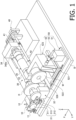
- FIGS. 1 and 2 are perspective views of a wheel test device 1 according to a first embodiment of the present invention.
- FIG. 1 is a front side view and
- FIG. 2 is a rear side view.
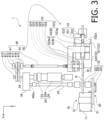
- FIG. 3 is a plan view of the wheel test device 1.
- a direction from lower right to upper left is defined as an X-axis direction
- a direction from upper right to lower left is defined as a Y-axis direction
- a direction from bottom to top is defined as a Z-axis direction.
- the X-axis direction and the Y-axis direction are horizontal directions orthogonal to each other, and the Z-axis direction is a vertical direction.
- Arbitrary straight lines respectively extending in the X-axis direction, the Y-axis direction, and the Z-axis direction are referred to as an X-axis, a Y-axis, and a Z-axis, respectively.
- the X-axis positive direction is referred to as left
- the X-axis negative direction is referred to as right
- the Y-axis positive direction is referred to as front
- the Y-axis negative direction is referred to as rear
- the Z-axis positive direction is referred to as up
- the Z-axis negative direction is referred to as down.
- the wheel test device 1 is a device capable of simulating an interaction between a rail and a wheel that occurs when a railway vehicle is running, and evaluating, for example, an adhesion property and the like between the rail and the wheel.
- a rail wheel R of which outer periphery having a cross-sectional shape that simulates a rail head is used, and both the rail wheel R and a wheel for tests (hereinafter referred to as a "test wheel W”) are rotated in a state where the test wheel W is pressed against the rail wheel R, whereby the interaction between the rail and the wheel when a railway vehicle is running is simulated.
- the wheel test device 1 includes a drive system DS that drives the rail wheel R and the test wheel W.
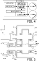
- FIG. 4 is a block diagram showing a schematic configuration of the drive system DS.
- the drive system DS includes an actuating section AS that generates mechanical power (hereinafter simply referred to as "power") and a transmitting section TS that transmits the power generated by the actuating section AS to the rail wheel R and the test wheel W which are targets to be driven, and constitutes a power circulation system together with the rail wheel R and the test wheel W, as will be described later.
- the actuating section AS includes a rotary drive device 10 (a speed control drive device) capable of controlling rotation speed of a driven object, and a torque generating device 20 (a torque control drive device) capable of controlling torque to be applied to the driven object.
- a rotary drive device 10 a speed control drive device
- a torque generating device 20 a torque control drive device capable of controlling torque to be applied to the driven object.
- the drive system DS of the present embodiment by adopting a configuration in which drive control is divided into speed control and torque control and dedicated drive units perform speed control and torque control, respectively, it is made possible to drive at high speed (or at high acceleration) and high torque while using a motor having a relatively small capacity. Furthermore, the drive system DS employs a power circulation system, thereby realizing a higher energy utilization efficiency than those of the conventional devices.
- the transmitting section TS includes a first transmission section 30 and a second transmission section 40.
- the torque generating device 20 also constitutes a part of the transmitting section TS.
- the first transmission section 30 transmits rotation output from the rotary drive device 10 to the rail wheel R and the torque generating device 20.
- the torque generating device 20 adds power generated by the torque generating device 20 itself to the power transmitted from the rotary drive device 10 and outputs the added power.
- the second transmission section 40 transmits the output of the torque generating device 20 to the test wheel W.
- the rail wheel R and the test wheel W are attached to the wheel test device 1 so that they are arranged in the radial direction with their rotation axes parallel to each other.
- the test wheel W is pressed against the rail wheel R, and the test wheel W and the rail wheel R are driven to rotate in directions opposite to each other at substantially the same peripheral speed (i.e., a linear speed of an outer peripheral surface) in a state where an outer peripheral surface (tread surface) of the test wheel W is in contact with an outer peripheral surface (top surface) of the rail wheel R.
- the transmitting section TS together with the test wheel W and the rail wheel R constitutes a power circulation system (i.e., a loop of power transmission shafts).
- the torque generating device 20 applies torque to the power circulation system by giving a phase difference between an input shaft (first transmission section 30) and an output shaft (second transmission section 40).
- the wheel test device 1 can apply torque (or tangential force) to the test wheel W without substantially absorbing the generated power, and thus the wheel test device 1 can be operated with relatively little energy consumption.
- the first transmission section 30 of the present embodiment is configured so that the rail wheel R and the test wheel W are rotationally driven at the same peripheral speed in opposite directions with respect to each other in a state where the operation of the torque generating device 20 (specifically, the second electric motor 22 described later) is stopped. It should be noted that a configuration may be adopted in which a difference in peripheral speed occurs between the rail wheel R and the test wheel W in a state where the operation of the torque generating device 20 is stopped. However, in this case, since the amount of operation of the torque generating device 20 increases in order to compensate for the difference in peripheral speed, the energy consumption increases.
- the first transmission section 30 of the present embodiment is configured so that the rail wheel R and the torque generating device 20 are rotationally driven at the same rotation speed
- a configuration may be adopted in which the rail wheel R and the torque generating device 20 are rotated at different rotation speeds as long as the rail wheel R and the test wheel W are rotationally driven at substantially the same peripheral speed.
- the rotary drive device 10 includes a tension adjustment table 11 and a first electric motor 12 (a speed control motor) installed on the tension adjustment table 11.
- the first electric motor 12 of the present embodiment is a so-called inverter motor whose drive is controlled by an inverter, but another type of motor, such as a servo motor or a stepping motor, in which rotation speed can be controlled, may be used for the first electric motor 12.
- the rotary drive device 10 may include a reducer for reducing the rotation output from the first electric motor 12.
- the tension adjustment table 11 will be described later.
- the first transmission section 30 includes a first belt mechanism 31, a rail wheel support unit 32, a shaft 33, and a gear box 34 (gear device).
- the first belt mechanism 31 includes a drive pulley 311 driven by the rotary drive device 10, a driven pulley 312 attached to an input shaft (one of shafts 321 described later) of the rail wheel support unit 32, and a belt 313 wound around the drive pulley 311 and the driven pulley 312.
- the rotation output from the rotary drive device 10 is transmitted to the rail wheel support unit 32 by the first belt mechanism 31 of the first transmission section 30.
- the belt 313 of the present embodiment is a V-ribbed belt having a plurality of V-shaped ribs arranged in a width direction, but may be another type of belt such as a V-belt having a trapezoidal cross-sectional shape, a toothed belt, a flat belt, or a round belt.
- the first belt mechanism 31 of the present embodiment includes a single belt transmission unit including a drive pulley 311, a driven pulley 312, and a belt 313, but may include two or more belt transmission units connected in parallel or in series.
- the transmission from the rotary drive device 10 to the rail wheel support unit 32 is not limited to belt transmission, but other types of winding transmission such as chain transmission or wire transmission, or other transmission systems such as gear transmission may be used.
- the rotary drive device 10 and the rail wheel support unit 32 may be disposed coaxially (i.e., so that the rotation axes or the center lines are coincident with each other) and an output shaft of the rotary drive device 10 and an input shaft of the rail wheel support unit 32 may be directly connected to each other.
- the tension adjustment table 11 of the rotary drive device 10 includes a fixed frame 111 fixed to a base B and a movable frame 112 to which the rotary drive device 10 is attached.
- the movable frame 112 is pivotally connected to the fixed frame 111 via a rod 114R extending in the Y-axis direction at a right end portion of the movable frame 112, so that an inclination around the Y-axis can be adjusted.
- a distance between the drive pulley 311 ( FIG. 1 ) and the driven pulley 312 can be changed by changing the inclination of the movable frame 112, whereby it is made possible to adjust the tension of the belt 313 wound around the drive pulley 311 and the driven pulley 312.
- the rail wheel support unit 32 includes a pair of bearings 322 and a pair of shafts 321.
- the pair of bearings 322 are arranged across the rail wheel R, in front of and behind the rail wheel R (i.e., arranged in the Y-axis direction), with the rotation axes thereof oriented the Y-axis direction, and are coaxially arranged.
- One shaft 321 is rotatably supported by the front bearing 322, and the other shaft 321 is rotatably supported by the rear bearing 322.
- the shafts 321 are flanged shafts each provided with a flange for mounting the rail wheel R at one end thereof, and are removably and coaxially mounted on respective side surfaces of the rail wheel R by bolts.
- the driven pulley 312 of the first belt mechanism 31 is attached to the other end of the front shaft 321.
- One end of the shaft 33 is connected to the other end of the rear shaft 321.
- the other end of the shaft 33 is connected to an input shaft 342a of the gear box 34.
- the rail wheel support unit 32 (specifically, the shafts 321) functions as power distributing means for distributing the power generated by the first electric motor 12 and transmitted by the first belt mechanism 31 to the rail wheel R and the shaft 33 (and finally to the test wheel W).
- the coupling structure between the shafts 321 and the rail wheel R is not limited to the coupling by the flange, but may be another coupling structure such as, for example, a structure in which the shaft 321 is fitted into a through hole provided at the center of the rail wheel R.
- the rail wheel support unit 32 includes a rotary encoder 323 (rotation speed detecting means) for detecting a rotation speed of the rail wheel R.
- FIG. 5 is a schematic cross-sectional view of the gear box 34 and its periphery cut along a horizontal plane.
- the gearbox 34 includes a case 341, a pair of first bearings 343 and a pair of second bearings 345 attached to the case 341, a first gear 342 (an input gear) rotatably supported by the pair of first bearings 343, and a second gear 344 (an output gear) rotatably supported by the pair of second bearings 345.
- the first gear 342 and the second gear 344 are arranged side by side in the X-axis direction with the rotation axes oriented in the Y-axis direction so that their teeth mesh with each other, and are housed in the case 341.
- One end of the first gear 342 is the input shaft 342a of the gear box 34 and is connected to the other end of the shaft 33.
- a flange formed at one end of the second gear 344 is an output shaft 344a of the gear box 34 and is connected to a flange (an input shaft 211b) formed at one end of a later-described casing 21 of the torque generating device 20.
- the second gear 344 is formed with a cylindrical through hole 344b centered on the rotation axis.
- An output shaft 24 of the torque generating device 20, which will be described later, is inserted into the through hole 344b from one end of the second gear 344 (the left end in FIG. 5 , i.e., the front end of the output shaft 344a), penetrates the second gear 344, and a front end thereof protrudes from the other end of the second gear 344.
- the first gear 342 and the second gear 344 have the same number of teeth, and thus a gear ratio of the gear box 34 is 1.
- the gear ratio of the gear box 34 may be set to a value other than 1 as long as the test wheel W and the rail wheel R can be rotated in the opposite direction at substantially the same peripheral speed.
- the transmission from the shaft 33 to the torque generating device 20 is not limited to the gear transmission, but other transmission systems such as, for example, a winding transmission such as a belt transmission or a chain transmission may be used.
- FIG. 6 is a schematic cross-sectional view of the torque generating device 20, the gear box 34, and the periphery thereof taken along a plane perpendicular to the X-axis direction.
- the torque generating device 20 includes a main body 20A (rotating part) rotationally driven by the rotary drive device 10, and a pair of bearing units 25 and 26 for rotatably supporting the main body 20A.
- the main body 20A includes a substantially cylindrical casing 21 (rotating frame) supported by bearing units 25 and 26, a second electric motor 22 and a reducer 23 attached to the casing 21, and an output shaft 24.
- the output shaft 24 is disposed coaxially with the casing 21.
- a shaft 221 and a rotor 222 of the second electric motor 22 which will be described later may be disposed coaxially with the casing 21.
- the second electric motor 22 in this embodiment is an AC servo motor
- other types of electric motor capable of controlling driving amount (rotation angle) such as a DC servo motor or a stepping motor
- a DC servo motor or a stepping motor may be used as the second electric motor 22.
- an ultra-low inertia high power type AC servo motor of which moment of inertia of a rotating part is 0.01 kg ⁇ m 2 or less (more preferably 0.008 kg ⁇ m 2 or less) and a rated output is 3 kW to 60 kW (more practically 7 kW to 37 kW) is used as a result, it is possible to generate rapid torque change (e.g., a vibration torque of a high frequency exceeding 500 Hz or 1 kHz).
- the casing 21 has a substantially cylindrical first cylindrical part 212 and a substantially cylindrical second cylindrical part 214 (a motor housing part), a connecting part 213 that connects the first cylindrical part 212 and the second cylindrical part 214, a first shaft part 211 connected to the first cylindrical part 212, and a second shaft part 215 connected to the second cylindrical part 214.
- the first shaft part 211, the first cylindrical part 212, the connecting part 213, the second cylindrical part 214, and the second shaft part 215 are all cylindrical members having a hollow portion passing through in the axial direction, and are coaxially connected in this order to form the cylindrical casing 21.
- the casing 21 is supported at the first shaft part 211 by the bearing unit 25 and at the second shaft part 215 by the bearing unit 26.
- a flange formed at the tip end of the first shaft part 211 is the input shaft 211b ( FIG. 5 ) of the torque generating device 20, and is connected to the output shaft 344a of the gear box 34.
- FIG. 7 is a vertical cross-sectional view showing a schematic configuration of the second electric motor 22.
- the second electric motor 22 includes a shaft 221, a rotor 222 composed of a permanent magnet or the like and integrally coupled with the shaft 221, a tubular stator 223 provided with a coil 223a on its inner periphery, a pair of flanges 224 and 226 attached to both ends of the stator 223 so as to close openings, a pair of bearings 225 and 227 attached to the respective flanges 224 and 226, and a rotary encoder RE for detecting an angular position (phase) of the shaft 221.
- the shaft 221 is rotatably supported by the pair of bearings 225 and 227.
- One end (the right end in FIG. 7 ) of the shaft 221 protrudes to the outside through the flange 224 and the bearing 225 and serves as an output shaft of the second electric motor 22.
- the other end (the left end in FIG. 7 ) of the shaft 221 is connected to the rotary encoder RE.
- the second electric motor 22 is housed in a hollow portion (compartment C1) of the second cylindrical part 214 of the casing 21.
- One end (left end in FIG. 6 ) of the connecting part 213 of the casing 21 is formed with an inner flange part 213a projecting to the inner periphery.
- the stator 223 ( FIG. 7 ) of the second electric motor 22 is fixed to the second cylindrical part 214 via a plurality of rod-shaped coupling members 217 radially arranged around the rotation axis of the torque generating device 20.
- the coupling members 217 for example, stud bolts or full-threaded bolts having male screws formed at both ends are used.
- the flange 224 ( FIG. 7 ) of the second electric motor 22 is supported by the inner flange part 213a of the connecting part 213.
- the reducer 23 is housed in a compartment C2 surrounded by the connecting part 213 and the first cylindrical part 212 of the casing 21.
- the shaft 221 of the second electric motor 22 is connected to an input shaft 231 of the reducer 23, and the output shaft 24 of the torque generating device 20 is connected to an output shaft 232 of the reducer 23.
- the output shaft 24 may be directly connected to the shaft 221 of the second electric motor 22 without providing the reducer 23 in the torque generating device 20.
- a case 233 of the reducer 23 is fixed to the other end of the connecting part 213. That is, the flange 224 of the second electric motor 22 ( FIG. 7 ) and the case 233 of the reducer 23 are integrally coupled to each other by a single cylindrical connecting part 213. Therefore, the second electric motor 22 and the reducer 23 are integrally coupled with high rigidity, and it is made difficult to apply bending moment to the shaft 221. As a result, friction that the shaft 221 receives from the bearings 225 and 227 ( FIG. 7 ) can be reduced, and thus accuracy of torque control by the torque generating device 20 improves.
- the output shaft 24 of the torque generating device 20 passes through the hollow portions of the first shaft part 211 of the casing 21 and the gear box 34 (specifically, the second gear 344) and protrudes to the rear of the gear box 34.
- a bearing 211a and a bearing 344c for rotatably supporting the output shaft 24 are provided on the inner peripheries of the first shaft part 211 of the casing 21 and the second gear 344 of the gearbox 34, respectively.
- Two drive pulleys 411 of a second belt mechanism 41 which will be described later, are attached to a distal end portion of the output shaft 24 protruding rearward from the gear box 34.
- the distal end portion of the output shaft 24 is rotatably supported by a bearing unit 414 of the second belt mechanism 41.
- a slip ring part 27 is provided adjacent to the front side (left side in FIG. 6 ) of the bearing unit 26.
- the slip ring part 27 includes a movable part 27A that rotates together with the main body 20A of the torque generating device 20 and a fixed part 27B that is fixed to the base B.
- the movable part 27A includes a ring support tube 271 coaxially connected to the second shaft part 215 of the torque generating device 20, and a plurality of slip rings 272 coaxially attached to an outer periphery of the ring support tube 271 at intervals in the axial direction.
- a cable 228 of the second electric motor 22 of the torque generating device 20 passes through the second shaft part 215 of the casing 21.
- a plurality of electric wires constituting the cable 228 pass through a hollow portion of the ring support tube 271 and are connected to the corresponding slip rings 272.
- the fixed part 27B includes a brush support part 274, a plurality of brushes 273 supported by the brush support part 274, and a bearing part 275 that rotatably supports a tip portion of the ring support tube 271.
- the brushes 273 are arranged at intervals in the Y-axis direction so as to be in contact with outer peripheral surfaces of the corresponding slip rings 272.
- the brushes 273 are wired and connected to a servo amplifier 22a and the like which will be described later.
- a rotary encoder 28 for detecting the rotation speed of the ring support tube 271 (i.e., the rotation speed of the casing 21 being the input shaft of the torque generating device 20) is attached to the bearing part 275.
- the second transmission section 40 includes a second belt mechanism 41, a slide type constant velocity joint 42, and a wheel support unit 50.
- the second belt mechanism 41 includes two sets of belt transmission units each including a drive pulley 411, a driven pulley 412, and a belt 413, a bearing unit 414, a shaft 415, and a pair of bearing units 416.
- the two drive pulleys 411 are attached to the distal end portion of the output shaft 24 of the torque generating device 20 passing through the gear box 34.
- the bearing unit 414 rotatably supports the distal end portion of the output shaft 24.
- An additional bearing unit 414 may be provided between the gear box 34 and the drive pulley 411 so that the distal end of the output shaft 24 is supported by a pair of bearing units 414.
- the drive pulley 411 is directly attached to the output shaft 24 of the torque generating device 20, but a shaft for supporting the drive pulley 411 may be provided separately from the output shaft 24 so that the shaft connected to the output shaft 24 is supported by the bearing unit 414.
- the two driven pulleys 412 are attached to the shaft 415 rotatably supported by the pair of bearing units 416.
- Each belt 413 is wound around corresponding drive pulley 411 and driven pulley 412.
- the belt 413 of the present embodiment is a toothed belt having a core wire of a steel wire.
- the belt 413 may be a belt having a core wire formed of a so-called super fiber such as carbon fiber, aramid fiber, or ultra-high molecular weight polyethylene fiber.
- a lightweight and high-strength core wire such as a carbon core wire formed of carbon fiber, it becomes possible to drive at a high acceleration (or to apply a high driving/braking force to the test wheel W) using a motor having a relatively low output, and thus it becomes possible to reduce the size of the wheel test device 1.
- a lightweight (i.e., low inertia) belt 413 having a core wire formed of the so-called super fiber may be used as the belt 413.
- a general automotive or industrial timing belt may be used as the belt 413.
- a flat belt or a V-belt may be used as the belt 413 in place of the toothed belt.
- These belts that can be used as the belt 413 can also be used as the belt 313 of the first belt mechanism 31.
- the second belt mechanism 41 of the present embodiment includes a pair of belt transmission units connected in parallel, but may include a single belt transmission unit or three or more belt transmission units connected in parallel.
- the transmission from the torque generating device 20 to the to the slide type constant velocity joint 42 is not limited to belt transmission, and other types of winding transmission such as chain transmission or wire transmission, or other transmission systems such as gear transmission may be used.
- the torque generating device 20 and the slide type constant velocity joint 42 may be arranged in a substantially straight line (or in a V-shape), and the output shaft 24 of the torque generating device 20 and the input shaft of the slide type constant velocity joint 42 may be directly connected.
- the wheel support unit 50 is connected to the torque generating device 20 via the slide type constant velocity joint 42.
- one end portion (i.e., an input shaft) of the slide type constant velocity joint 42 is connected to the shaft 415 of the second belt mechanism 41, and the other end portion (i.e., an output shaft) of the slide type constant velocity joint 42 is connected to a later-described spindle 527 of the wheel support unit 50.
- the slide type constant velocity joint 42 is configured to be able to smoothly transmit rotation without rotation fluctuation regardless of an operating angle (i.e., an angle formed by the input shaft and the output shaft).
- the slide type constant velocity joint 42 also has a variable length (transmission distance) in the axial direction.
- the spindle 527 is supported so that its position can change.
- the slide type constant velocity joint 42 By connecting the spindle 527 to the shaft 415 of the second belt mechanism 41 (or to the output shaft 24 of the torque generating device 20) via the slide type constant velocity joint 42, even if the position of the spindle 527 changes, the slide type constant velocity joint 42 flexibly follows this change, so that large strain is prevented from being applied to the spindle 527 and the shaft 415 (or to the output shaft 24 of the torque generating device 20), and rotation can be smoothly transmitted to the spindle 527.
- the slide type constant velocity joint 42 By using the slide type constant velocity joint 42, the rotation speed transmitted to the spindle 527 is prevented from changing depending on the position of the spindle 527 (or the operating angle of the slide type constant velocity joint 42).
- the wheel support unit 50 includes a fixed base 51, and a main body 52 and a wheel load applying unit 53 disposed on the fixed base 51.
- the main body 52 includes a movable base 522, a pair of linear guides 521 that support the movable base 522 so as to be movable in the X-axis direction with respect to the fixed base 51, a support frame 523 installed on the movable base 522, a bearing unit 528 attached to the support frame 523, a spindle 527 rotatably supported by the bearing unit 528, a torque sensor 524 and a detection gear 525 coaxially attached to the spindle 527, and a rotation detector 526 for detecting rotation of the detection gear 525.
- the linear guide 521 is a guide-way type circulating rolling bearing provided with a linear rail (guideway) and a carriage capable of running on the rail via rolling elements. However, other types of linear guide mechanism may be used as the linear guide 521.
- the linear guide 521 constitutes apart of the wheel load applying unit 53.
- the detection gear 525 and the rotation detector 526 constitute rotation speed detecting means for detecting the rotation speed of the spindle 527.
- the support frame 523 has a support column 523a fixed to the movable base 522 and an arm 523b fixed to the support column 523a.
- the support column 523a of the present embodiment is an L-shaped bracket, other types of support column 523a may be used.
- the support column 523a and the arm 523b may be integrally formed.
- the arm 523b is a substantially L-shaped structure as seen from above, having a base part 523b1 extending rearward from an upper portion of the support column 523a and a trunk part 523b2 extending leftward from a rear end portion of the base part 523b1.
- a hollow portion penetrating in the Y-axis direction is formed at a distal end portion of the trunk part 523b2.
- a drive shaft (specifically, an assembly of the slide type constant velocity joint 42, the torque sensor 524, the detection gear 525, and the spindle 527 connected to each other) passes through the hollow portion.
- the bearing unit 528 is attached to the arm 523b. More specifically, the bearing unit 528 is attached to a front surface of the front end portion of the trunk part 523b2 with the rotation axis thereof oriented in the Y-axis direction.
- the bearing unit 528 is provided with a plurality of three component force sensors 529 (tangential force detecting means and first lateral pressure detecting means) for detecting force received from the spindle 527.
- the three component force sensors 529 are piezoelectric force sensors, but other types of force sensors may be used as the three component force sensors 529.
- the spindle 527 is connected to the output shaft of the slide type constant velocity joint 42 via the detection gear 525 and the torque sensor 524.
- the detection gear 525 and the torque sensor 524 are housed in a hollow portion formed at a distal end portion of the trunk part 523b2.
- the test wheel W is attached to a mounting portion provided at a distal end portion of the spindle 527.
- the torque sensor 524 detects a torque acting on the spindle 527 (i.e., acting on the test wheel W).
- the rotation detector 526 is disposed to face an outer peripheral surface of the detection gear 525 and is fixed to the trunk part 523b2 of the support frame 523.
- the rotation detector 526 is, for example, a non-contact type rotation detector such as an optical type, an electromagnetic type, or a magnetoelectric type, and detects a change in an angular position of the detection gear 525.
- the wheel load applying unit 53 is a mechanism that applies a wheel load of a predetermined size to the test wheel W by moving the main body 52 of the wheel support unit 50 in the X-axis direction and pressing the test wheel W attached to the spindle 527 against the rail wheel R.
- the wheel load applying unit 53 includes a motor 531, a motion converter 532 that converts a rotational motion of the motor 531 into a linear motion in the X-axis direction, and a wheel load detector 533 ( FIG. 10 ) for detecting a wheel load acting on the test wheel W.
- the motor 531 is an AC servo motor, other types of electric motor capable of controlling drive amount (rotation angle), such as a DC servo motor or a stepping motor, may be used as the motor 531.
- the motion converter 532 of the present embodiment is, for example, a screw jack in which a reducer such as a worm gear device is combined with a feed screw mechanism such as a ball screw, but other types of motion converter may be used.
- a linearly moving part 532a of the motion converter 532 is fixed to the support frame 523 via the wheel load detector 533.
- the motor 531 drives the motion converter 532
- the support frame 523 and the spindle 527 supported by the support frame 523 move in the X-axis direction together with the linearly moving part 532a.
- the test wheel W attached to the spindle 527 moves back and forth with respect to the rail wheel R.
- the motor 531 drives the motion converter 532 further in a direction in which the test wheel W moves toward the rail wheel R (i.e., in the X-axis positive direction) in a state where the test wheel W and the rail wheel R are in contact with each other, the test wheel W is pressed against the rail wheel R, and the wheel load is applied to the test wheel W.
- the wheel load detector 533 is a force sensor that detects a force in the X-axis direction (i.e., wheel load) acting on the test wheel W via the support frame 523 and the spindle 527 by the wheel load applying unit 53.
- the wheel load detector 533 of the present embodiment is a load cell of a strain gauge type, but other types of force sensor such as a piezoelectric force sensor may be used as the wheel load detector 533.
- a control part 70 which will be described later controls the drive of the motor 531 so that the wheel load of a predetermined magnitude is applied to the test wheel W based on the detection result by the wheel load detector 533.
- FIG. 8 is a block diagram showing a schematic configuration of a control system CS of the wheel test device 1.
- the control system CS includes a control part 70 that controls operation of the entire wheel test device 1, a measuring part 80 that performs various measurements based on signals from various detectors provided to the wheel test device 1, and an interface part 90 for performing input from and output to the outside.
- the second electric motor 22 and the motor 531 are connected to the control part 70 via servo amplifiers 22a and 531a, respectively, and the first electric motor 12 is connected to the control part 70 via a driver 12a (inverter circuit).
- the rotary encoders 28 and 323, the torque sensor 524, the three component force sensors 529, and the wheel load detector 533 are connected to the measuring part 80 via amplifiers 28a, 323a, 524a, 529a, and 533a, respectively.
- FIG. 8 only one representative set is shown among a plurality of sets of three component force sensors 529 and amplifiers 529a provided to the wheel test device 1.
- the rotation detector 526 embedded with an amplifier circuit and an analog-to-digital conversion circuit is directly connected to the measuring part 80.
- the measuring part 80 measures the rotation speed of the rail wheel R on the basis of a signal from a rotary encoder 323, measures the rotation speed of the input shaft (casing 21) of the torque generating device 20 on the basis of a signal from the rotary encoder 28, measures the rotation speed of the spindle 527 (i.e., the rotation speed the test wheel W) on the basis of a signal from the rotation detector 526.
- the measuring part 80 further measures the torque acting on the test wheel W on the basis of a signal from the torque sensor 524, measures a tangential force (longitudinal creep force) and a lateral pressure (thrust load) acting on the test wheel W on the basis of signals from a plurality of three component force sensors 529, and measures the wheel load on the basis of a signal from a wheel load detector 533.
- the measuring part 80 functions as a first rotation speed measuring means for measuring the rotation speed of the rail wheel R, a second rotation speed measuring means for measuring the rotation speed of the torque generating device 20, a third rotation speed measuring means for measuring the rotation speed of the test wheel W, a torque measuring means for measuring the torque acting on the test wheel W, a tangential force measuring means for measuring the tangential force acting on the test wheel W, a lateral pressure measuring means for measuring the lateral pressure acting on the test wheel W, and a wheel load measuring means for measuring the wheel load acting on the test wheel W.
- the measuring part 80 transmits these measured values to the control part 70.
- the wheel test device 1 of the present embodiment includes many measuring means and corresponding detecting means because it is a relatively versatile device, the wheel test device 1 need not be provided with all of these measuring means and detecting means, but may be provided with one or more sets of measuring means and detecting means which are appropriately selected according to the matters to be examined by the test.
- phase information of the shaft detected by the rotary encoder RE embedded in each servo motor (the second electric motor 22 and the motor 531) is input to the control part 70 via the corresponding servo amplifiers 22a, 531a.
- the interface part 90 includes, for example, one or more of a user interface for performing input/output with a user, a network interface for connecting with various networks such as the LAN (Local Area Network), and various communication interfaces such as the USB (Universal Serial Bus) and the GPIB (General Purpose Interface Bus) for connecting with external devices.
- the user interface includes, for example, one or more of various operation switches, various display devices such as indicators and LCD (Liquid Crystal Display), various pointing devices such as a mouse and a touch pad, and various input/output devices such as a touch screen, a video camera, a printer, a scanner, a buzzer, a speaker, a microphone, and a memory card reader/writer.
- the control part 70 controls the driving of the first electric motor 12 based on setting data of the rotation speed (or peripheral speed) of the rail wheel R inputted through the interface part 90 and the measurement result of the rotation speed of the rail wheel R by the measuring part 80 so that the rail wheel R rotates at a set rotation speed.
- the control part 70 controls the driving of the motor 531 of the wheel load applying unit 53 based on wheel load setting data input through the interface part 90 and the wheel load measurement result by the measuring part 80 so that a set wheel load is applied to the test wheel W.
- the control part 70 controls the driving of the second electric motor 22 of the torque generating device 20 based on setting data of the torque of the test wheel W inputted through the interface part 90 and the measurement result of the torque of the test wheel W by the measuring part 80 so that a set torque is applied to the test wheel W.
- the control part 70 drives the motor 531 of the wheel load applying unit 53 in a state where the rail wheel R and the test wheel W are attached to the wheel test device 1 to bring the test wheel W close to and into contact with the rail wheel R, and applies the set wheel load to the test wheel W.
- the set value of the wheel load a constant value or a variable value that varies with time can be set.
- the control part 70 drives the first electric motor 12 of the rotary drive device 10 so that the rail wheel R rotates at the set rotation speed.
- the set value of the rotation speed of the rail wheel R a constant value or a variable value that varies with time can be set.
- the control part 70 also controls the second electric motor 22 so that the torque of the test wheel W is 0 (no load) until the rotation speed of the rail wheel R reaches the set value.
- the control part 70 controls the driving of the second electric motor 22 of the torque generating device 20 so that the set torque is applied to the test wheel W.
- the set value of the torque of the test wheel W a constant value or a variable value that varies with time can be set.
- the driving of the second electric motor 22 may be controlled so that the set torque is applied to the test wheel W from the start of the rotational drive of the rail wheel R.
- the control part 70 rotates the rail wheel R and the test wheel W while continuously measuring the rotation speed of the rail wheel R, the torque of the test wheel W, the tangential force, the lateral pressure, and the wheel load for a predetermined time (test time).
- the control part 70 stores each measurement value in a storage device 71 of the control part 70 (or, for example, a storage means accessible by the control part 70 such as a server connected to the control part 70 via a LAN) in association with the measured time.
- the control part 70 controls the driving of the second electric motor 22 of the torque generating device 20 so that the torque of the test wheel W becomes 0. Then, the control part 70 controls the first electric motor 12 of the rotary drive device 10 to gradually reduce the rotation speed of the rail wheel R to stop the rotation, and then drives the motor 531 of the wheel load applying unit 53 to move the test wheel W away from the rail wheel R by a predetermined distance to end the test.
- test procedure described above is only an example of test procedures that can be performed using the wheel test device 1, and various other test procedures can be performed.
- FIG. 9 is a plan view showing a schematic configuration of a wheel test device 1000 according to a second embodiment of the present invention.
- FIG. 10 is a front view showing a schematic configuration of the wheel test device 1000.
- the wheel test device 1000 includes a wheel support unit 1500 in which a lateral pressure applying function, an attack angle applying function and a cant angle applying function are added to the wheel support unit 50 of the first embodiment.
- the wheel support unit 1500 of the wheel test device 1000 includes a lateral pressure applying unit 54, a cant angle applying unit 55, and an attack angle applying unit 56 in addition to the wheel load applying unit 53.
- the wheel support unit 1500 also includes three movable bases (a first movable base 522A, a second movable base 522B, and a third movable base 522C).
- the lateral pressure applying unit 54 is a mechanism that applies lateral pressure (thrust load) to the test wheel W.
- the lateral pressure includes lateral creep force (a component of adhesive force in the axial direction of the test wheel W) and flange reaction force (force caused by a contact between a flange of the test wheel W and a gauge corner of the rail wheel R), and the latter flange reaction force is applied (or adjusted to a predetermined value) by the lateral pressure applying unit 54.
- the lateral pressure applying unit 54 includes a plurality of (for example, three) linear guides 541 that support the first movable base 522A with respect to the base 51 so as to be movable in the Y-axis direction, a motor 542 ( FIG. 9 ) attached to the base B together with the fixed base 51, a motion converter 543 ( FIG. 9 ) that converts rotational motion of the motor 542 into a linear motion in the Y-axis direction, and a lateral pressure detector 544 ( FIG. 9 ) that detects the lateral pressure acting on the test wheel W.
- the linear guide 541 is a guide-way type circulating rolling bearing having the same configuration as the linear guide 521, but other types of linear guide mechanism may be used as the linear guide 541.
- the lateral pressure detector 544 (second lateral pressure detecting means) is used to detect the lateral pressure when the flange reaction force is applied, and the three component force sensors 529 (first lateral pressure detecting means) are used to detect the lateral pressure when the flange reaction force is not applied.
- the wheel test device 1000 may be configured to detect the lateral pressure by using the three component force sensors 529 even when the flange reaction force is applied without providing the lateral pressure detector 544.
- the wheel test device 1000 may also be configured to detect the lateral pressure by using the lateral pressure detector 544 even when the flange reaction force is not applied.
- the wheel test device 1000 may be configured to detect static lateral pressure (mainly the flange reaction force) by using the lateral pressure detector 544 and detect dynamic lateral pressure (mainly the lateral creep force) by using the three component force sensors 529.
- the motor 542 in the present embodiment is an AC servo motor
- other types of motor capable of controlling driving amount (rotation angle) such as a DC servo motor or a stepping motor, may be used as the motor 542.
- the motion converter 543 in the present embodiment is a feed screw mechanism such as a ball screw, other types of motion converter may be used.
- the screw shaft of the motion converter 543 is rotatably supported by a pair of bearings attached to the fixed base 51, and one end of the screw shaft is connected to a shaft of the motor 542.
- a nut (linearly moving part) of the motion converter 543 is fixed to the first movable base 522A via the lateral pressure detector 544.
- the first movable base 522A moves in the Y-axis direction together with the nut of the motion converter 543.
- the test wheel W supported by the first movable base 522A also moves in the Y-axis direction, changing a position of the test wheel W in the axial direction with respect to the rail wheel R.
- a flange reaction force is applied to the test wheel W.
- a magnitude of the flange reaction force varies depending on the position of the test wheel W in the Y-axis direction.
- the motor 542 is connected to the control part 70 via a servo amplifier 542a.
- the lateral pressure detector 544 is connected to the measuring part 80 via an amplifier 544a.
- Phase information of the shaft detected by the rotary encoder RE embedded in the motor 542 is input to the control part 70 through the servo amplifier 542a.
- the measuring part 80 measures the lateral pressure acting on the test wheel W on the basis of a signal from the lateral pressure detector 544.
- the control part 70 controls the driving of the motor 542 on the basis of lateral pressure setting data input through the interface part 90 and the lateral pressure measurement result by the measuring part 80 so that a set lateral pressure is applied to the test wheel W.
- the cant angle applying unit 55 is a mechanism having a function of applying a cant angle to the test wheel W.
- the cant angle applying unit 55 includes a vertically extending swing support shaft 551 attached to one of the first movable base 522A and the second movable base 522B, and a bearing 552 attached to the other of the first movable base 522A and the second movable base 522B and that rotatably supports the swing support shaft 551.
- the second movable base 522B is supported by the swing support shaft 551 and the bearing 552 so as to be rotatable about a rotation axis A1 of the bearing 552, which is a vertical line.
- the bearing 552 is disposed substantially immediately below a contact position P at which the test wheel W contacts the rail wheel R (in the present embodiment, a right end of the rail wheel R) so that the rotation axis A1 passes through the contact position P.
- the rotation axis A1 is a tangent line between the rail wheel R and the test wheel W at the contact position P. Therefore, when the second movable base 522B rotates about the rotation axis A1, the test wheel W swings about the contact position P around the Z axis (in other words, the test wheel W rotates about the common tangent line between the test wheel W and the rail wheel R), and an inclination (i.e., a cant angle) about the tangent line with respect to the rail wheel R changes.
- the cant angle applying unit 55 includes a curved guide 553 that supports the second movable base 522B at an outer peripheral portion apart from the rotation axis A1 so that the second movable base 522B can swing about the rotation axis A1 with respect to the first movable base 522A.
- the curved guide 553 is a guideway type circulating rolling bearing including a curved rail (guideway) and a carriage capable of running on the rail via rolling elements, but other types of curved guide mechanism may be used as the curved guide 553.
- the cant angle applying unit 55 includes a motor 554 ( FIG. 9 ) and a motion converter 555 that converts rotational motion of the motor 554 into a linear motion in the Y-axis direction.
- the motor 554 in the present embodiment is an AC servo motor, other types of motor capable of controlling driving amount (rotation angle), such as a DC servo motor or a stepping motor, may be used as the motor 554.
- the motion converter 555 in the present embodiment is a feed screw mechanism such as a ball screw, other types of motion converter may be used.
- a screw shaft 555a of the motion converter 555 is rotatably supported by a pair of bearings, and one end of the screw shaft 555a a is connected to a shaft of the motor 554.
- the bearings supporting the screw shaft 555a are not shown.
- the motor 554 and the pair of bearings of the motion converter 555 are attached to a not-shown rotary table which is rotatable about a vertical shaft provided on the first movable base 522A.
- the motor 554 is disposed so that the shaft thereof intersects perpendicularly with a rotation axis of the rotary table.
- a nut 555b (linearly moving part) of the motion converter 555 is coupled to the second movable base 522B via a hinge 556 so as to be rotatable about a vertical axis.
- the hinge 556 attached to the second movable base 522B moves substantially in the Y-axis direction together with the nut 555b. Accordingly, the second movable base 522B rotates about the rotation axis A1, and the test wheel W supported by the second movable base 522B rotates about the contact position P, whereby the cant angle is changed.
- the motor 554 is connected to the control part 70 via a servo amplifier 554a. Phase information of the shaft detected by a rotary encoder RE embedded in the motor 554 is input to the control part 70 through the servo amplifier 554a.
- the control part 70 calculates a current value of the cant angle based on a signal from the rotary encoder RE embedded in the motor 554.
- the control part 70 controls the driving of the motor 554 based on setting data of the cant angle inputted through the interface part 90 and the current value of the cant angle so that a set cant angle is given to the test wheel W.
- the attack angle applying unit 56 is a mechanism having a function of applying an attack angle to the test wheel W.
- the attack angle is an angle formed between the rail and the wheel, and more specifically, an angle about a vertical axis (i.e., an angle in the yawing direction) formed between a width direction of the rail (railroad tie direction) and the axial direction of the wheel.
- the attack angle is defined as an angle between the rotation axis of the rail wheel R and the rotation axis of the test wheel W about the X axis.
- a support frame 1523 of the wheel support unit 1500 of the present embodiment includes a box-shaped support column 1523a fixed to the third movable base 522C, and an arm 1523b connected to the support column 1523a so as to be rotatable about a rotation axis A2 extending in the X-axis direction.
- the arm 1523b is a substantially L-shaped member as seen from above, and includes a base part 1523b1 extending in the Y-axis direction and connected to an upper portion of the support column 1523a, and a trunk part 1523b2 extending to the left from a rear end portion of the base part 1523b1.
- a swing support shaft 561 protrudes in the X-axis direction.
- a bearing 562 that rotatably support the swing support shaft 561 is attached to an upper portion of the support column 1523a.
- the arm 1523b is supported by the bearing 562 via the swing support shaft 561 so as to be rotatable about the rotation axis A2 extending in the Y-axis direction.
- the bearing 562 is disposed such that the rotation axis A2 passes through the contact position P. That is, the rotation axis A2 is a straight line perpendicularly passing through the tread surface of the test wheel W.
- the swing support shaft 561 and the bearing 562 form a part of the attack angle applying unit 56.
- the attack angle applying unit 56 includes a motor 564, and a motion converter 563 that converts rotational motion of the motor 564 into a linear motion in the Z-axis direction.
- the motor 564 in the present embodiment is an AC servo motor, other types of motor capable of controlling driving amount (rotation angle), such as a DC servo motor or a stepping motor, may be used as the motor 564.
- the motion converter 563 in the present embodiment is a feed screw mechanism such as a ball screw, other types of motion converter may be used.
- the screw shaft of the motion converter 563 is rotatably supported by a pair of bearings, and one end of the screw shaft is connected to a shaft of the motor 564 via a bevel gear.
- the screw shaft of the motion converter 563 may be directly connected to the shaft of the motor 564.
- the motor 564 and the motion converter 563 are attached to a swing frame coupled to the third movable base 522C via a hinge having a rotation shaft extending in the X-axis direction so as to be rotatable (i.e., swingable) within a predetermined angular range about the rotation shaft of the hinge.
- a nut (linearly moving part) of the motion converter 563 is coupled to the arm 1523b of the support frame 1523 via a hinge having a rotation shaft extending in the X-axis direction so as to be swingable about the rotation shaft of the hinge.
- the hinge attached to the arm 1523b moves together with the nut substantially in the Z-axis direction. Accordingly, the test wheel W supported by the arm 1523b together with the arm 1523b rotates about the rotation axis A2 passing through the contact position P (in other words, a straight line perpendicular to the tread surface of the test wheel), whereby an attack angle is given.
- the motor 564 is connected to the control part 70 via a servo amplifier 564a. Phase information of the shaft detected by a rotary encoder RE embedded in the motor 564 is input to the control part 70 through the servo amplifier 564a.
- the control part 70 calculates the current value of the attack angle based on the signal of the rotary encoder RE embedded in the motor 564.
- the control part 70 controls the driving of the motor 564 based on setting data of the attack angle input through the interface part 90 and the current value of the attack angle so that a set attack angle is given to the test wheel W.
- the linearly moving part 532a of the motion converter 532 of the wheel load applying unit 53 is fixed to the support column 1523a of the support frame 1523 via the wheel load detector 533.
- the linearly moving part 532a of the motion converter 532 is disposed so that the center line thereof coincides with the rotation axis A2. This prevents a large moment of force from being applied to the support frame 1523 when the wheel load is applied.
- the wheel load applying unit 53 is provided on the wheel support unit 50 and is configured to adjust the wheel load by moving the test wheel W back and forth with respect to the rail wheel R.
- the present invention is not limited to this configuration.
- the wheel load applying unit may be provided to the rail wheel support unit and the wheel load may be adjusted by moving the rail wheel R back and forth with respect to the test wheel W.
- the rail wheel R is connected to the rotary drive device 10 without the torque generating device 20 therebetween, and the test wheel W is connected to the rotary drive device 10 via the torque generating device 20.
- the present invention is not limited to this configuration.
- the rail wheel R may be connected to the rotary drive device 10 via the torque generating device 20, and the test wheel W may be connected to the rotary drive device 10 without the torque generating device 20 therebetween.
- two torque generating devices 20 may be provided, and the rail wheel R may be connected to the rotary drive device 10 via one torque generating device 20, and the test wheel W may be connected to the rotary drive device 10 through another torque generating device 20.
- a plurality of three component force sensors are provided to the wheel support unit 50, and the measuring part 80 measures the torque and wheel load acting on the test wheel W based on the detection results of the plurality of three component force sensors.
- the present invention is not limited to this configuration.
- the torque and wheel load may be measured based on detection results of a plurality of two component force sensors or one component force sensors.
- the function of the power distributing means is incorporated in the rail wheel support unit 32, but the power distributing means may be separated from the rail wheel support unit 32.
- the first transmission section 30 may not be connected to the rail wheel support unit 32, and the rotary drive device 10 and the first transmission section 30 may be connected via additional power transmission means (e.g., winding transmission or gear transmission).
- additional power transmission means e.g., winding transmission or gear transmission.
- the drive pulley 311 of the first belt mechanism 31 and the shaft of the rotary drive device 10 to which a pulley or gear of the additional power transmission means is to be mounted function as the power distributing means.
- the fixed base 51 and the spindle 527 are coupled to each other via the lateral pressure applying unit 54, the cant angle applying unit 55, the wheel load applying unit 53, and the attack angle applying unit 56 in this order.
- the present invention is not limited to this configuration.
- the lateral pressure applying unit 54, the cant angle applying unit 55, the wheel load applying unit 53, and the attack angle applying unit 56 may be connected in any order.
Landscapes
- Physics & Mathematics (AREA)
- General Physics & Mathematics (AREA)
- Testing Of Devices, Machine Parts, Or Other Structures Thereof (AREA)
Abstract
Description
- The present invention relates to a wheel test device.
- There is known a test device for simulating and examining an interaction between a rail and a wheel during when a railway vehicle is running. For example,
Japanese Patent Provisional Publication No. 2007-271447 - Since the test device disclosed in
Patent Document 1 is driven by a single electric motor, when performing a test for applying a large torque to the wheel while rotating the wheel at a high speed, it is necessary to use a large-capacity electric motor, and thus there is a problem that power consumption during the test becomes enormous. - The present invention has been made in view of the foregoing circumstances, and it is an object of the present invention to reduce power consumption of a wheel test device.
- According to an embodiment of the present invention, there is provided a wheel test device including a rail wheel support unit configured to rotatably support a rail wheel, a wheel support unit configured to rotatably support a test wheel in a state where the test wheel is in contact with the rail wheel, a first electric motor configured to rotate the rail wheel and the test wheel, and a torque generating device configured to generate torque to be applied to the test wheel, the torque generating device including a rotating frame rotationally driven by the first electric motor, and a second electric motor mounted on the rotating frame, and at least one of the rail wheel and the test wheel being connected to the first electric motor via the torque generating device.
- The above-described wheel test device may include power distributing means configured to distribute power generated by the first electric motor to the rail wheel and the test wheel.
- In the above-described wheel test device, the rail wheel and the test wheel may be configured to rotate in opposite directions at substantially the same peripheral speed when the operation of the second electric motor is stopped.
- In the above-described wheel test device, the torque generating device may include an output shaft disposed coaxially with the rotating frame.
- In the above-described wheel test device, the torque generating device may include a bearing unit configured to rotatably support the rotating frame, the rotating frame may have a cylindrical shaft part supported by the bearing unit, a bearing may be provided on an inner periphery of the shaft part; and the output shaft may pass through a hollow portion of the shaft part and may be rotatably supported by the bearing.
- In the above-described wheel test device, the first electric motor may be disposed coaxially with the rotating frame.
- In the above-described wheel test device, the second electric motor may be fixed to the rotating frame via a plurality of rod-shaped connecting members arranged radially about a rotation axis of the rotating frame.
- In the above-described wheel test device, the rotating frame may include a cylindrical motor housing part configured to house the second electric motor.
- The above-described wheel test device may include a control part configured to control the first electric motor and the second electric motor, a rotation speed measuring means configured to measure a rotation speed of the rail wheel, and a torque measuring means configured to measure the torque of the test wheel, and the control part may control driving of the first electric motor based on measurement result of the rotation speed measuring means, and may control driving of the second electric motor based on measurement result of the torque measuring means.
- The above-described wheel test device may include a wheel load applying unit configured to apply a wheel load to the test wheel by moving one of the test wheel and the rail wheel forward and backward with respect to the other.
- The above-described wheel test device may include an attack angle applying unit configured to apply an attack angle by rotating one of the test wheel and the rail wheel about a straight line perpendicular to a tread surface of the test wheel with respect to the other.
- The above-described wheel test device may include a cant angle applying unit configured to apply a cant angle by rotating one of the test wheel and the rail wheel about a tangent line with respect to the other.
- The above-described wheel test device may include a lateral pressure applying unit configured to apply lateral pressure to the test wheel by moving one of the test wheel and the rail wheel in an axial direction with respect to the other.
- According to an embodiment of the present invention, it is possible to reduce power consumption of the wheel test device.
-
- [
FIG. 1] FIG. 1 is a perspective view of a wheel test device according to a first embodiment of the present invention. - [
FIG. 2] FIG. 2 is a perspective view of the wheel test device according to the first embodiment of the present invention. - [
FIG. 3] FIG. 3 is a plan view of the wheel test device according to the first embodiment of the present invention. - [
FIG. 4] FIG. 4 is a block diagram showing a schematic configuration of a drive system. - [
FIG. 5] FIG. 5 is a cross-sectional view showing a schematic configuration of a gear box. - [
FIG. 6] FIG. 6 is a cross-sectional view showing a schematic configuration of a torque generating device and its periphery. - [
FIG. 7] FIG. 7 is a cross-sectional view showing a schematic configuration of a second electric motor. - [
FIG. 8] FIG. 8 is a block diagram showing a schematic configuration of a control system. - [
FIG. 9] FIG. 9 is a plan view showing a schematic configuration of a wheel test device according to a second embodiment of the present invention. - [
FIG. 10] FIG. 10 is a front view showing a schematic configuration of the wheel test device according to the second embodiment of the present invention. - Hereinafter, embodiments of the present invention will be described with reference to the drawings. In the following description, the same or corresponding elements will be denoted by the same or corresponding numerals, and redundant description will be omitted. In each drawing, in a case where a plurality of item whose numerals are in common are shown, the numeral is not necessarily assigned to all of the plurality of items, and assignment of the numeral to some of the plurality of item is appropriately omitted.
-
FIGS. 1 and2 are perspective views of awheel test device 1 according to a first embodiment of the present invention.FIG. 1 is a front side view andFIG. 2 is a rear side view.FIG. 3 is a plan view of thewheel test device 1. - In
FIG. 1 , as shown by the coordinate axes, a direction from lower right to upper left is defined as an X-axis direction, a direction from upper right to lower left is defined as a Y-axis direction, and a direction from bottom to top is defined as a Z-axis direction. The X-axis direction and the Y-axis direction are horizontal directions orthogonal to each other, and the Z-axis direction is a vertical direction. Arbitrary straight lines respectively extending in the X-axis direction, the Y-axis direction, and the Z-axis direction are referred to as an X-axis, a Y-axis, and a Z-axis, respectively. The X-axis positive direction is referred to as left, the X-axis negative direction is referred to as right, the Y-axis positive direction is referred to as front, the Y-axis negative direction is referred to as rear, the Z-axis positive direction is referred to as up, and the Z-axis negative direction is referred to as down. - The
wheel test device 1 is a device capable of simulating an interaction between a rail and a wheel that occurs when a railway vehicle is running, and evaluating, for example, an adhesion property and the like between the rail and the wheel. In the present embodiment, a rail wheel R of which outer periphery having a cross-sectional shape that simulates a rail head is used, and both the rail wheel R and a wheel for tests (hereinafter referred to as a "test wheel W") are rotated in a state where the test wheel W is pressed against the rail wheel R, whereby the interaction between the rail and the wheel when a railway vehicle is running is simulated. - The
wheel test device 1 includes a drive system DS that drives the rail wheel R and the test wheel W.FIG. 4 is a block diagram showing a schematic configuration of the drive system DS. The drive system DS includes an actuating section AS that generates mechanical power (hereinafter simply referred to as "power") and a transmitting section TS that transmits the power generated by the actuating section AS to the rail wheel R and the test wheel W which are targets to be driven, and constitutes a power circulation system together with the rail wheel R and the test wheel W, as will be described later. - The actuating section AS includes a rotary drive device 10 (a speed control drive device) capable of controlling rotation speed of a driven object, and a torque generating device 20 (a torque control drive device) capable of controlling torque to be applied to the driven object. In the drive system DS of the present embodiment, by adopting a configuration in which drive control is divided into speed control and torque control and dedicated drive units perform speed control and torque control, respectively, it is made possible to drive at high speed (or at high acceleration) and high torque while using a motor having a relatively small capacity. Furthermore, the drive system DS employs a power circulation system, thereby realizing a higher energy utilization efficiency than those of the conventional devices.
- The transmitting section TS includes a
first transmission section 30 and asecond transmission section 40. The torque generatingdevice 20 also constitutes a part of the transmitting section TS. Thefirst transmission section 30 transmits rotation output from therotary drive device 10 to the rail wheel R and thetorque generating device 20. Thetorque generating device 20 adds power generated by thetorque generating device 20 itself to the power transmitted from therotary drive device 10 and outputs the added power. Thesecond transmission section 40 transmits the output of the torque generatingdevice 20 to the test wheel W. - The rail wheel R and the test wheel W are attached to the
wheel test device 1 so that they are arranged in the radial direction with their rotation axes parallel to each other. When performing test, the test wheel W is pressed against the rail wheel R, and the test wheel W and the rail wheel R are driven to rotate in directions opposite to each other at substantially the same peripheral speed (i.e., a linear speed of an outer peripheral surface) in a state where an outer peripheral surface (tread surface) of the test wheel W is in contact with an outer peripheral surface (top surface) of the rail wheel R. At this time, the transmitting section TS together with the test wheel W and the rail wheel R constitutes a power circulation system (i.e., a loop of power transmission shafts). Thetorque generating device 20 applies torque to the power circulation system by giving a phase difference between an input shaft (first transmission section 30) and an output shaft (second transmission section 40). By the adoption of the power circulation system, thewheel test device 1 can apply torque (or tangential force) to the test wheel W without substantially absorbing the generated power, and thus thewheel test device 1 can be operated with relatively little energy consumption. - The
first transmission section 30 of the present embodiment is configured so that the rail wheel R and the test wheel W are rotationally driven at the same peripheral speed in opposite directions with respect to each other in a state where the operation of the torque generating device 20 (specifically, the secondelectric motor 22 described later) is stopped. It should be noted that a configuration may be adopted in which a difference in peripheral speed occurs between the rail wheel R and the test wheel W in a state where the operation of the torque generatingdevice 20 is stopped. However, in this case, since the amount of operation of the torque generatingdevice 20 increases in order to compensate for the difference in peripheral speed, the energy consumption increases. Also, although thefirst transmission section 30 of the present embodiment is configured so that the rail wheel R and thetorque generating device 20 are rotationally driven at the same rotation speed, a configuration may be adopted in which the rail wheel R and thetorque generating device 20 are rotated at different rotation speeds as long as the rail wheel R and the test wheel W are rotationally driven at substantially the same peripheral speed. - As shown in
FIG. 1-3 , therotary drive device 10 includes a tension adjustment table 11 and a first electric motor 12 (a speed control motor) installed on the tension adjustment table 11. The firstelectric motor 12 of the present embodiment is a so-called inverter motor whose drive is controlled by an inverter, but another type of motor, such as a servo motor or a stepping motor, in which rotation speed can be controlled, may be used for the firstelectric motor 12. Therotary drive device 10 may include a reducer for reducing the rotation output from the firstelectric motor 12. The tension adjustment table 11 will be described later. - The
first transmission section 30 includes afirst belt mechanism 31, a railwheel support unit 32, ashaft 33, and a gear box 34 (gear device). - As shown in
FIG. 1 , thefirst belt mechanism 31 includes adrive pulley 311 driven by therotary drive device 10, a drivenpulley 312 attached to an input shaft (one ofshafts 321 described later) of the railwheel support unit 32, and abelt 313 wound around thedrive pulley 311 and the drivenpulley 312. - The rotation output from the
rotary drive device 10 is transmitted to the railwheel support unit 32 by thefirst belt mechanism 31 of thefirst transmission section 30. - The
belt 313 of the present embodiment is a V-ribbed belt having a plurality of V-shaped ribs arranged in a width direction, but may be another type of belt such as a V-belt having a trapezoidal cross-sectional shape, a toothed belt, a flat belt, or a round belt. - The
first belt mechanism 31 of the present embodiment includes a single belt transmission unit including adrive pulley 311, a drivenpulley 312, and abelt 313, but may include two or more belt transmission units connected in parallel or in series. - The transmission from the
rotary drive device 10 to the railwheel support unit 32 is not limited to belt transmission, but other types of winding transmission such as chain transmission or wire transmission, or other transmission systems such as gear transmission may be used. Therotary drive device 10 and the railwheel support unit 32 may be disposed coaxially (i.e., so that the rotation axes or the center lines are coincident with each other) and an output shaft of therotary drive device 10 and an input shaft of the railwheel support unit 32 may be directly connected to each other. - The tension adjustment table 11 of the
rotary drive device 10 will now be described. As shown inFIG. 2 , the tension adjustment table 11 includes a fixedframe 111 fixed to a base B and amovable frame 112 to which therotary drive device 10 is attached. Themovable frame 112 is pivotally connected to the fixedframe 111 via arod 114R extending in the Y-axis direction at a right end portion of themovable frame 112, so that an inclination around the Y-axis can be adjusted. A distance between the drive pulley 311 (FIG. 1 ) and the drivenpulley 312 can be changed by changing the inclination of themovable frame 112, whereby it is made possible to adjust the tension of thebelt 313 wound around thedrive pulley 311 and the drivenpulley 312. - As shown in
FIGS. 2 and3 , the railwheel support unit 32 includes a pair ofbearings 322 and a pair ofshafts 321. The pair ofbearings 322 are arranged across the rail wheel R, in front of and behind the rail wheel R (i.e., arranged in the Y-axis direction), with the rotation axes thereof oriented the Y-axis direction, and are coaxially arranged. - One
shaft 321 is rotatably supported by thefront bearing 322, and theother shaft 321 is rotatably supported by therear bearing 322. Theshafts 321 are flanged shafts each provided with a flange for mounting the rail wheel R at one end thereof, and are removably and coaxially mounted on respective side surfaces of the rail wheel R by bolts. - The driven
pulley 312 of thefirst belt mechanism 31 is attached to the other end of thefront shaft 321. One end of theshaft 33 is connected to the other end of therear shaft 321. The other end of theshaft 33 is connected to aninput shaft 342a of thegear box 34. - Part of the power transmitted by the
first belt mechanism 31 to the railwheel support unit 32 is given to the rail wheel R, and the rest is given to the shaft 33 (and to the test wheel W via theshaft 33, thetorque generating device 20, and the second transmission section 40). That is, the rail wheel support unit 32 (specifically, the shafts 321) functions as power distributing means for distributing the power generated by the firstelectric motor 12 and transmitted by thefirst belt mechanism 31 to the rail wheel R and the shaft 33 (and finally to the test wheel W). - The coupling structure between the
shafts 321 and the rail wheel R is not limited to the coupling by the flange, but may be another coupling structure such as, for example, a structure in which theshaft 321 is fitted into a through hole provided at the center of the rail wheel R. - As shown in
FIG. 3 , the railwheel support unit 32 includes a rotary encoder 323 (rotation speed detecting means) for detecting a rotation speed of the rail wheel R. -
FIG. 5 is a schematic cross-sectional view of thegear box 34 and its periphery cut along a horizontal plane. Thegearbox 34 includes acase 341, a pair offirst bearings 343 and a pair ofsecond bearings 345 attached to thecase 341, a first gear 342 (an input gear) rotatably supported by the pair offirst bearings 343, and a second gear 344 (an output gear) rotatably supported by the pair ofsecond bearings 345. - The
first gear 342 and thesecond gear 344 are arranged side by side in the X-axis direction with the rotation axes oriented in the Y-axis direction so that their teeth mesh with each other, and are housed in thecase 341. One end of thefirst gear 342 is theinput shaft 342a of thegear box 34 and is connected to the other end of theshaft 33. A flange formed at one end of thesecond gear 344 is anoutput shaft 344a of thegear box 34 and is connected to a flange (aninput shaft 211b) formed at one end of a later-describedcasing 21 of thetorque generating device 20. - The
second gear 344 is formed with a cylindrical throughhole 344b centered on the rotation axis. Anoutput shaft 24 of thetorque generating device 20, which will be described later, is inserted into the throughhole 344b from one end of the second gear 344 (the left end inFIG. 5 , i.e., the front end of theoutput shaft 344a), penetrates thesecond gear 344, and a front end thereof protrudes from the other end of thesecond gear 344. - In the present embodiment, the
first gear 342 and thesecond gear 344 have the same number of teeth, and thus a gear ratio of thegear box 34 is 1. The gear ratio of thegear box 34 may be set to a value other than 1 as long as the test wheel W and the rail wheel R can be rotated in the opposite direction at substantially the same peripheral speed. - The transmission from the
shaft 33 to thetorque generating device 20 is not limited to the gear transmission, but other transmission systems such as, for example, a winding transmission such as a belt transmission or a chain transmission may be used. -
FIG. 6 is a schematic cross-sectional view of thetorque generating device 20, thegear box 34, and the periphery thereof taken along a plane perpendicular to the X-axis direction. - The
torque generating device 20 includes amain body 20A (rotating part) rotationally driven by therotary drive device 10, and a pair of bearingunits main body 20A. - The
main body 20A includes a substantially cylindrical casing 21 (rotating frame) supported by bearingunits electric motor 22 and areducer 23 attached to thecasing 21, and anoutput shaft 24. Theoutput shaft 24 is disposed coaxially with thecasing 21. Ashaft 221 and arotor 222 of the secondelectric motor 22 which will be described later may be disposed coaxially with thecasing 21. By arranging the secondelectric motor 22 coaxially with thecasing 21, unbalance of themain body 20A is reduced, and it becomes possible to rotate themain body 20A smoothly (i.e., with less unnecessary fluctuation of the rotation speed and torque). Although the secondelectric motor 22 in this embodiment is an AC servo motor, other types of electric motor capable of controlling driving amount (rotation angle), such as a DC servo motor or a stepping motor, may be used as the secondelectric motor 22. In the present embodiment, as the secondelectric motor 22, an ultra-low inertia high power type AC servo motor of which moment of inertia of a rotating part is 0.01 kg·m2 or less (more preferably 0.008 kg·m2 or less) and a rated output is 3 kW to 60 kW (more practically 7 kW to 37 kW) is used. As a result, it is possible to generate rapid torque change (e.g., a vibration torque of a high frequency exceeding 500 Hz or 1 kHz). - The
casing 21 has a substantially cylindrical firstcylindrical part 212 and a substantially cylindrical second cylindrical part 214 (a motor housing part), a connectingpart 213 that connects the firstcylindrical part 212 and the secondcylindrical part 214, afirst shaft part 211 connected to the firstcylindrical part 212, and asecond shaft part 215 connected to the secondcylindrical part 214. Thefirst shaft part 211, the firstcylindrical part 212, the connectingpart 213, the secondcylindrical part 214, and thesecond shaft part 215 are all cylindrical members having a hollow portion passing through in the axial direction, and are coaxially connected in this order to form thecylindrical casing 21. Thecasing 21 is supported at thefirst shaft part 211 by the bearingunit 25 and at thesecond shaft part 215 by the bearingunit 26. A flange formed at the tip end of thefirst shaft part 211 is theinput shaft 211b (FIG. 5 ) of thetorque generating device 20, and is connected to theoutput shaft 344a of thegear box 34. -
FIG. 7 is a vertical cross-sectional view showing a schematic configuration of the secondelectric motor 22. The secondelectric motor 22 includes ashaft 221, arotor 222 composed of a permanent magnet or the like and integrally coupled with theshaft 221, atubular stator 223 provided with acoil 223a on its inner periphery, a pair offlanges stator 223 so as to close openings, a pair ofbearings respective flanges shaft 221. - The
shaft 221 is rotatably supported by the pair ofbearings FIG. 7 ) of theshaft 221 protrudes to the outside through theflange 224 and thebearing 225 and serves as an output shaft of the secondelectric motor 22. The other end (the left end inFIG. 7 ) of theshaft 221 is connected to the rotary encoder RE. - As shown in
FIG. 6 , the secondelectric motor 22 is housed in a hollow portion (compartment C1) of the secondcylindrical part 214 of thecasing 21. One end (left end inFIG. 6 ) of the connectingpart 213 of thecasing 21 is formed with aninner flange part 213a projecting to the inner periphery. The stator 223 (FIG. 7 ) of the secondelectric motor 22 is fixed to the secondcylindrical part 214 via a plurality of rod-shapedcoupling members 217 radially arranged around the rotation axis of thetorque generating device 20. As thecoupling members 217, for example, stud bolts or full-threaded bolts having male screws formed at both ends are used. The flange 224 (FIG. 7 ) of the secondelectric motor 22 is supported by theinner flange part 213a of the connectingpart 213. - The
reducer 23 is housed in a compartment C2 surrounded by the connectingpart 213 and the firstcylindrical part 212 of thecasing 21. Theshaft 221 of the secondelectric motor 22 is connected to aninput shaft 231 of thereducer 23, and theoutput shaft 24 of thetorque generating device 20 is connected to anoutput shaft 232 of thereducer 23. Theoutput shaft 24 may be directly connected to theshaft 221 of the secondelectric motor 22 without providing thereducer 23 in thetorque generating device 20. - A
case 233 of thereducer 23 is fixed to the other end of the connectingpart 213. That is, theflange 224 of the second electric motor 22 (FIG. 7 ) and thecase 233 of thereducer 23 are integrally coupled to each other by a singlecylindrical connecting part 213. Therefore, the secondelectric motor 22 and thereducer 23 are integrally coupled with high rigidity, and it is made difficult to apply bending moment to theshaft 221. As a result, friction that theshaft 221 receives from thebearings 225 and 227 (FIG. 7 ) can be reduced, and thus accuracy of torque control by thetorque generating device 20 improves. - The
output shaft 24 of thetorque generating device 20 passes through the hollow portions of thefirst shaft part 211 of thecasing 21 and the gear box 34 (specifically, the second gear 344) and protrudes to the rear of thegear box 34. Abearing 211a and a bearing 344c for rotatably supporting theoutput shaft 24 are provided on the inner peripheries of thefirst shaft part 211 of thecasing 21 and thesecond gear 344 of thegearbox 34, respectively. - Two drive pulleys 411 of a
second belt mechanism 41, which will be described later, are attached to a distal end portion of theoutput shaft 24 protruding rearward from thegear box 34. The distal end portion of theoutput shaft 24 is rotatably supported by abearing unit 414 of thesecond belt mechanism 41. - A
slip ring part 27 is provided adjacent to the front side (left side inFIG. 6 ) of the bearingunit 26. Theslip ring part 27 includes amovable part 27A that rotates together with themain body 20A of thetorque generating device 20 and afixed part 27B that is fixed to the base B. - The
movable part 27A includes aring support tube 271 coaxially connected to thesecond shaft part 215 of thetorque generating device 20, and a plurality ofslip rings 272 coaxially attached to an outer periphery of thering support tube 271 at intervals in the axial direction. - A
cable 228 of the secondelectric motor 22 of thetorque generating device 20 passes through thesecond shaft part 215 of thecasing 21. A plurality of electric wires constituting thecable 228 pass through a hollow portion of thering support tube 271 and are connected to the corresponding slip rings 272. - The
fixed part 27B includes abrush support part 274, a plurality ofbrushes 273 supported by thebrush support part 274, and abearing part 275 that rotatably supports a tip portion of thering support tube 271. Thebrushes 273 are arranged at intervals in the Y-axis direction so as to be in contact with outer peripheral surfaces of the corresponding slip rings 272. Thebrushes 273 are wired and connected to aservo amplifier 22a and the like which will be described later. - A
rotary encoder 28 for detecting the rotation speed of the ring support tube 271 (i.e., the rotation speed of thecasing 21 being the input shaft of the torque generating device 20) is attached to thebearing part 275. - As shown in
FIG. 3 , thesecond transmission section 40 includes asecond belt mechanism 41, a slide type constant velocity joint 42, and awheel support unit 50. - The
second belt mechanism 41 includes two sets of belt transmission units each including adrive pulley 411, a drivenpulley 412, and abelt 413, abearing unit 414, ashaft 415, and a pair of bearingunits 416. - As described above, the two
drive pulleys 411 are attached to the distal end portion of theoutput shaft 24 of thetorque generating device 20 passing through thegear box 34. Thebearing unit 414 rotatably supports the distal end portion of theoutput shaft 24. - An
additional bearing unit 414 may be provided between thegear box 34 and thedrive pulley 411 so that the distal end of theoutput shaft 24 is supported by a pair of bearingunits 414. In the present embodiment, thedrive pulley 411 is directly attached to theoutput shaft 24 of thetorque generating device 20, but a shaft for supporting thedrive pulley 411 may be provided separately from theoutput shaft 24 so that the shaft connected to theoutput shaft 24 is supported by the bearingunit 414. - The two driven
pulleys 412 are attached to theshaft 415 rotatably supported by the pair of bearingunits 416. - Each
belt 413 is wound around correspondingdrive pulley 411 and drivenpulley 412. - The
belt 413 of the present embodiment is a toothed belt having a core wire of a steel wire. Thebelt 413 may be a belt having a core wire formed of a so-called super fiber such as carbon fiber, aramid fiber, or ultra-high molecular weight polyethylene fiber. By using a lightweight and high-strength core wire such as a carbon core wire formed of carbon fiber, it becomes possible to drive at a high acceleration (or to apply a high driving/braking force to the test wheel W) using a motor having a relatively low output, and thus it becomes possible to reduce the size of thewheel test device 1. When a motor having the same output is used, it is possible to increase the performance of thewheel test device 1 by using a lightweight (i.e., low inertia)belt 413 having a core wire formed of the so-called super fiber. A general automotive or industrial timing belt may be used as thebelt 413. A flat belt or a V-belt may be used as thebelt 413 in place of the toothed belt. These belts that can be used as thebelt 413 can also be used as thebelt 313 of thefirst belt mechanism 31. - The
second belt mechanism 41 of the present embodiment includes a pair of belt transmission units connected in parallel, but may include a single belt transmission unit or three or more belt transmission units connected in parallel. - The transmission from the
torque generating device 20 to the to the slide type constant velocity joint 42 is not limited to belt transmission, and other types of winding transmission such as chain transmission or wire transmission, or other transmission systems such as gear transmission may be used. Thetorque generating device 20 and the slide type constant velocity joint 42 may be arranged in a substantially straight line (or in a V-shape), and theoutput shaft 24 of thetorque generating device 20 and the input shaft of the slide type constant velocity joint 42 may be directly connected. - The
wheel support unit 50 is connected to thetorque generating device 20 via the slide type constant velocity joint 42. Specifically, one end portion (i.e., an input shaft) of the slide type constant velocity joint 42 is connected to theshaft 415 of thesecond belt mechanism 41, and the other end portion (i.e., an output shaft) of the slide type constant velocity joint 42 is connected to a later-describedspindle 527 of thewheel support unit 50. - The slide type constant velocity joint 42 is configured to be able to smoothly transmit rotation without rotation fluctuation regardless of an operating angle (i.e., an angle formed by the input shaft and the output shaft). The slide type constant velocity joint 42 also has a variable length (transmission distance) in the axial direction.
- As will be described later, the
spindle 527 is supported so that its position can change. By connecting thespindle 527 to theshaft 415 of the second belt mechanism 41 (or to theoutput shaft 24 of the torque generating device 20) via the slide type constant velocity joint 42, even if the position of thespindle 527 changes, the slide type constant velocity joint 42 flexibly follows this change, so that large strain is prevented from being applied to thespindle 527 and the shaft 415 (or to theoutput shaft 24 of the torque generating device 20), and rotation can be smoothly transmitted to thespindle 527. By using the slide type constant velocity joint 42, the rotation speed transmitted to thespindle 527 is prevented from changing depending on the position of the spindle 527 (or the operating angle of the slide type constant velocity joint 42). - As shown in
FIG. 1 , thewheel support unit 50 includes a fixedbase 51, and amain body 52 and a wheelload applying unit 53 disposed on the fixedbase 51. - As shown in
FIG. 3 , themain body 52 includes amovable base 522, a pair oflinear guides 521 that support themovable base 522 so as to be movable in the X-axis direction with respect to the fixedbase 51, asupport frame 523 installed on themovable base 522, abearing unit 528 attached to thesupport frame 523, aspindle 527 rotatably supported by the bearingunit 528, atorque sensor 524 and adetection gear 525 coaxially attached to thespindle 527, and arotation detector 526 for detecting rotation of thedetection gear 525. Thelinear guide 521 is a guide-way type circulating rolling bearing provided with a linear rail (guideway) and a carriage capable of running on the rail via rolling elements. However, other types of linear guide mechanism may be used as thelinear guide 521. Thelinear guide 521 constitutes apart of the wheelload applying unit 53. Thedetection gear 525 and therotation detector 526 constitute rotation speed detecting means for detecting the rotation speed of thespindle 527. - The
support frame 523 has asupport column 523a fixed to themovable base 522 and anarm 523b fixed to thesupport column 523a. Although thesupport column 523a of the present embodiment is an L-shaped bracket, other types ofsupport column 523a may be used. Thesupport column 523a and thearm 523b may be integrally formed. Thearm 523b is a substantially L-shaped structure as seen from above, having a base part 523b1 extending rearward from an upper portion of thesupport column 523a and a trunk part 523b2 extending leftward from a rear end portion of the base part 523b1. A hollow portion penetrating in the Y-axis direction is formed at a distal end portion of the trunk part 523b2. A drive shaft (specifically, an assembly of the slide type constant velocity joint 42, thetorque sensor 524, thedetection gear 525, and thespindle 527 connected to each other) passes through the hollow portion. - The
bearing unit 528 is attached to thearm 523b. More specifically, thebearing unit 528 is attached to a front surface of the front end portion of the trunk part 523b2 with the rotation axis thereof oriented in the Y-axis direction. Thebearing unit 528 is provided with a plurality of three component force sensors 529 (tangential force detecting means and first lateral pressure detecting means) for detecting force received from thespindle 527. The threecomponent force sensors 529 are piezoelectric force sensors, but other types of force sensors may be used as the threecomponent force sensors 529. - The
spindle 527 is connected to the output shaft of the slide type constant velocity joint 42 via thedetection gear 525 and thetorque sensor 524. Thedetection gear 525 and thetorque sensor 524 are housed in a hollow portion formed at a distal end portion of the trunk part 523b2. The test wheel W is attached to a mounting portion provided at a distal end portion of thespindle 527. Thetorque sensor 524 detects a torque acting on the spindle 527 (i.e., acting on the test wheel W). - The
rotation detector 526 is disposed to face an outer peripheral surface of thedetection gear 525 and is fixed to the trunk part 523b2 of thesupport frame 523. Therotation detector 526 is, for example, a non-contact type rotation detector such as an optical type, an electromagnetic type, or a magnetoelectric type, and detects a change in an angular position of thedetection gear 525. - The wheel
load applying unit 53 is a mechanism that applies a wheel load of a predetermined size to the test wheel W by moving themain body 52 of thewheel support unit 50 in the X-axis direction and pressing the test wheel W attached to thespindle 527 against the rail wheel R. - The wheel
load applying unit 53 includes amotor 531, amotion converter 532 that converts a rotational motion of themotor 531 into a linear motion in the X-axis direction, and a wheel load detector 533 (FIG. 10 ) for detecting a wheel load acting on the test wheel W. - Although the
motor 531 is an AC servo motor, other types of electric motor capable of controlling drive amount (rotation angle), such as a DC servo motor or a stepping motor, may be used as themotor 531. - The
motion converter 532 of the present embodiment is, for example, a screw jack in which a reducer such as a worm gear device is combined with a feed screw mechanism such as a ball screw, but other types of motion converter may be used. A linearly movingpart 532a of themotion converter 532 is fixed to thesupport frame 523 via thewheel load detector 533. - When the
motor 531 drives themotion converter 532, thesupport frame 523 and thespindle 527 supported by thesupport frame 523 move in the X-axis direction together with the linearly movingpart 532a. As a result, the test wheel W attached to thespindle 527 moves back and forth with respect to the rail wheel R. When themotor 531 drives themotion converter 532 further in a direction in which the test wheel W moves toward the rail wheel R (i.e., in the X-axis positive direction) in a state where the test wheel W and the rail wheel R are in contact with each other, the test wheel W is pressed against the rail wheel R, and the wheel load is applied to the test wheel W. - The
wheel load detector 533 is a force sensor that detects a force in the X-axis direction (i.e., wheel load) acting on the test wheel W via thesupport frame 523 and thespindle 527 by the wheelload applying unit 53. Thewheel load detector 533 of the present embodiment is a load cell of a strain gauge type, but other types of force sensor such as a piezoelectric force sensor may be used as thewheel load detector 533. Acontrol part 70 which will be described later controls the drive of themotor 531 so that the wheel load of a predetermined magnitude is applied to the test wheel W based on the detection result by thewheel load detector 533. -
FIG. 8 is a block diagram showing a schematic configuration of a control system CS of thewheel test device 1. The control system CS includes acontrol part 70 that controls operation of the entirewheel test device 1, a measuringpart 80 that performs various measurements based on signals from various detectors provided to thewheel test device 1, and aninterface part 90 for performing input from and output to the outside. - The second
electric motor 22 and themotor 531 are connected to thecontrol part 70 viaservo amplifiers electric motor 12 is connected to thecontrol part 70 via adriver 12a (inverter circuit). - The
rotary encoders torque sensor 524, the threecomponent force sensors 529, and thewheel load detector 533 are connected to the measuringpart 80 viaamplifiers FIG. 8 , only one representative set is shown among a plurality of sets of threecomponent force sensors 529 andamplifiers 529a provided to thewheel test device 1. Therotation detector 526 embedded with an amplifier circuit and an analog-to-digital conversion circuit is directly connected to the measuringpart 80. - The measuring
part 80 measures the rotation speed of the rail wheel R on the basis of a signal from arotary encoder 323, measures the rotation speed of the input shaft (casing 21) of thetorque generating device 20 on the basis of a signal from therotary encoder 28, measures the rotation speed of the spindle 527 (i.e., the rotation speed the test wheel W) on the basis of a signal from therotation detector 526. The measuringpart 80 further measures the torque acting on the test wheel W on the basis of a signal from thetorque sensor 524, measures a tangential force (longitudinal creep force) and a lateral pressure (thrust load) acting on the test wheel W on the basis of signals from a plurality of threecomponent force sensors 529, and measures the wheel load on the basis of a signal from awheel load detector 533. That is, the measuringpart 80 functions as a first rotation speed measuring means for measuring the rotation speed of the rail wheel R, a second rotation speed measuring means for measuring the rotation speed of thetorque generating device 20, a third rotation speed measuring means for measuring the rotation speed of the test wheel W, a torque measuring means for measuring the torque acting on the test wheel W, a tangential force measuring means for measuring the tangential force acting on the test wheel W, a lateral pressure measuring means for measuring the lateral pressure acting on the test wheel W, and a wheel load measuring means for measuring the wheel load acting on the test wheel W. The measuringpart 80 transmits these measured values to thecontrol part 70. - Although the
wheel test device 1 of the present embodiment includes many measuring means and corresponding detecting means because it is a relatively versatile device, thewheel test device 1 need not be provided with all of these measuring means and detecting means, but may be provided with one or more sets of measuring means and detecting means which are appropriately selected according to the matters to be examined by the test. - The phase information of the shaft detected by the rotary encoder RE embedded in each servo motor (the second
electric motor 22 and the motor 531) is input to thecontrol part 70 via the correspondingservo amplifiers - The
interface part 90 includes, for example, one or more of a user interface for performing input/output with a user, a network interface for connecting with various networks such as the LAN (Local Area Network), and various communication interfaces such as the USB (Universal Serial Bus) and the GPIB (General Purpose Interface Bus) for connecting with external devices. The user interface includes, for example, one or more of various operation switches, various display devices such as indicators and LCD (Liquid Crystal Display), various pointing devices such as a mouse and a touch pad, and various input/output devices such as a touch screen, a video camera, a printer, a scanner, a buzzer, a speaker, a microphone, and a memory card reader/writer. - The
control part 70 controls the driving of the firstelectric motor 12 based on setting data of the rotation speed (or peripheral speed) of the rail wheel R inputted through theinterface part 90 and the measurement result of the rotation speed of the rail wheel R by the measuringpart 80 so that the rail wheel R rotates at a set rotation speed. - The
control part 70 controls the driving of themotor 531 of the wheelload applying unit 53 based on wheel load setting data input through theinterface part 90 and the wheel load measurement result by the measuringpart 80 so that a set wheel load is applied to the test wheel W. - The
control part 70 controls the driving of the secondelectric motor 22 of thetorque generating device 20 based on setting data of the torque of the test wheel W inputted through theinterface part 90 and the measurement result of the torque of the test wheel W by the measuringpart 80 so that a set torque is applied to the test wheel W. - Next, an example of a method of performing a test using the
wheel test device 1 will be described. First, thecontrol part 70 drives themotor 531 of the wheelload applying unit 53 in a state where the rail wheel R and the test wheel W are attached to thewheel test device 1 to bring the test wheel W close to and into contact with the rail wheel R, and applies the set wheel load to the test wheel W. As the set value of the wheel load, a constant value or a variable value that varies with time can be set. - Then, the
control part 70 drives the firstelectric motor 12 of therotary drive device 10 so that the rail wheel R rotates at the set rotation speed. As the set value of the rotation speed of the rail wheel R, a constant value or a variable value that varies with time can be set. Thecontrol part 70 also controls the secondelectric motor 22 so that the torque of the test wheel W is 0 (no load) until the rotation speed of the rail wheel R reaches the set value. - As the rotation speed of the rail wheel R reaches the set value, the
control part 70 controls the driving of the secondelectric motor 22 of thetorque generating device 20 so that the set torque is applied to the test wheel W. As the set value of the torque of the test wheel W, a constant value or a variable value that varies with time can be set. The driving of the secondelectric motor 22 may be controlled so that the set torque is applied to the test wheel W from the start of the rotational drive of the rail wheel R. - In this state, the
control part 70 rotates the rail wheel R and the test wheel W while continuously measuring the rotation speed of the rail wheel R, the torque of the test wheel W, the tangential force, the lateral pressure, and the wheel load for a predetermined time (test time). At this time, thecontrol part 70 stores each measurement value in astorage device 71 of the control part 70 (or, for example, a storage means accessible by thecontrol part 70 such as a server connected to thecontrol part 70 via a LAN) in association with the measured time. - When a predetermined time elapses, the
control part 70 controls the driving of the secondelectric motor 22 of thetorque generating device 20 so that the torque of the test wheel W becomes 0. Then, thecontrol part 70 controls the firstelectric motor 12 of therotary drive device 10 to gradually reduce the rotation speed of the rail wheel R to stop the rotation, and then drives themotor 531 of the wheelload applying unit 53 to move the test wheel W away from the rail wheel R by a predetermined distance to end the test. - The test procedure described above is only an example of test procedures that can be performed using the
wheel test device 1, and various other test procedures can be performed. - Next, a second embodiment of the present invention will be described. In the following description of the second embodiment, emphasis is placed on matters different from those of the first embodiment described above, and configurations that are the same as or correspond to those of the first embodiment are assigned the same or corresponding reference numerals, and redundant description is omitted.
-
FIG. 9 is a plan view showing a schematic configuration of awheel test device 1000 according to a second embodiment of the present invention.FIG. 10 is a front view showing a schematic configuration of thewheel test device 1000. - The
wheel test device 1000 includes awheel support unit 1500 in which a lateral pressure applying function, an attack angle applying function and a cant angle applying function are added to thewheel support unit 50 of the first embodiment. - As shown in
FIG. 9 , thewheel support unit 1500 of thewheel test device 1000 includes a lateralpressure applying unit 54, a cantangle applying unit 55, and an attackangle applying unit 56 in addition to the wheelload applying unit 53. As shown inFIG. 10 , thewheel support unit 1500 also includes three movable bases (a firstmovable base 522A, a secondmovable base 522B, and a thirdmovable base 522C). - The lateral
pressure applying unit 54 is a mechanism that applies lateral pressure (thrust load) to the test wheel W. The lateral pressure includes lateral creep force (a component of adhesive force in the axial direction of the test wheel W) and flange reaction force (force caused by a contact between a flange of the test wheel W and a gauge corner of the rail wheel R), and the latter flange reaction force is applied (or adjusted to a predetermined value) by the lateralpressure applying unit 54. - The lateral
pressure applying unit 54 includes a plurality of (for example, three)linear guides 541 that support the firstmovable base 522A with respect to the base 51 so as to be movable in the Y-axis direction, a motor 542 (FIG. 9 ) attached to the base B together with the fixedbase 51, a motion converter 543 (FIG. 9 ) that converts rotational motion of themotor 542 into a linear motion in the Y-axis direction, and a lateral pressure detector 544 (FIG. 9 ) that detects the lateral pressure acting on the test wheel W. Thelinear guide 541 is a guide-way type circulating rolling bearing having the same configuration as thelinear guide 521, but other types of linear guide mechanism may be used as thelinear guide 541. - In the present embodiment, the lateral pressure detector 544 (second lateral pressure detecting means) is used to detect the lateral pressure when the flange reaction force is applied, and the three component force sensors 529 (first lateral pressure detecting means) are used to detect the lateral pressure when the flange reaction force is not applied. The
wheel test device 1000 may be configured to detect the lateral pressure by using the threecomponent force sensors 529 even when the flange reaction force is applied without providing thelateral pressure detector 544. Alternatively, thewheel test device 1000 may also be configured to detect the lateral pressure by using thelateral pressure detector 544 even when the flange reaction force is not applied. Alternatively, thewheel test device 1000 may be configured to detect static lateral pressure (mainly the flange reaction force) by using thelateral pressure detector 544 and detect dynamic lateral pressure (mainly the lateral creep force) by using the threecomponent force sensors 529. - Although the
motor 542 in the present embodiment is an AC servo motor, other types of motor capable of controlling driving amount (rotation angle), such as a DC servo motor or a stepping motor, may be used as themotor 542. - Although the
motion converter 543 in the present embodiment is a feed screw mechanism such as a ball screw, other types of motion converter may be used. The screw shaft of themotion converter 543 is rotatably supported by a pair of bearings attached to the fixedbase 51, and one end of the screw shaft is connected to a shaft of themotor 542. A nut (linearly moving part) of themotion converter 543 is fixed to the firstmovable base 522A via thelateral pressure detector 544. When the screw shaft of themotion converter 543 is rotated by themotor 542, the firstmovable base 522A moves in the Y-axis direction together with the nut of themotion converter 543. As a result, the test wheel W supported by the firstmovable base 522A also moves in the Y-axis direction, changing a position of the test wheel W in the axial direction with respect to the rail wheel R. When the test wheel W is displaced in the Y-axis direction and the flange of the test wheel W is brought into contact with the rail wheel R, a flange reaction force is applied to the test wheel W. A magnitude of the flange reaction force varies depending on the position of the test wheel W in the Y-axis direction. - As shown in
FIG. 8 , themotor 542 is connected to thecontrol part 70 via aservo amplifier 542a. Thelateral pressure detector 544 is connected to the measuringpart 80 via anamplifier 544a. Phase information of the shaft detected by the rotary encoder RE embedded in themotor 542 is input to thecontrol part 70 through theservo amplifier 542a. - The measuring
part 80 measures the lateral pressure acting on the test wheel W on the basis of a signal from thelateral pressure detector 544. Thecontrol part 70 controls the driving of themotor 542 on the basis of lateral pressure setting data input through theinterface part 90 and the lateral pressure measurement result by the measuringpart 80 so that a set lateral pressure is applied to the test wheel W. - The cant
angle applying unit 55 is a mechanism having a function of applying a cant angle to the test wheel W. As shown inFIG. 10 , the cantangle applying unit 55 includes a vertically extendingswing support shaft 551 attached to one of the firstmovable base 522A and the secondmovable base 522B, and abearing 552 attached to the other of the firstmovable base 522A and the secondmovable base 522B and that rotatably supports theswing support shaft 551. The secondmovable base 522B is supported by theswing support shaft 551 and thebearing 552 so as to be rotatable about a rotation axis A1 of thebearing 552, which is a vertical line. - The
bearing 552 is disposed substantially immediately below a contact position P at which the test wheel W contacts the rail wheel R (in the present embodiment, a right end of the rail wheel R) so that the rotation axis A1 passes through the contact position P. The rotation axis A1 is a tangent line between the rail wheel R and the test wheel W at the contact position P. Therefore, when the secondmovable base 522B rotates about the rotation axis A1, the test wheel W swings about the contact position P around the Z axis (in other words, the test wheel W rotates about the common tangent line between the test wheel W and the rail wheel R), and an inclination (i.e., a cant angle) about the tangent line with respect to the rail wheel R changes. - The cant
angle applying unit 55 includes acurved guide 553 that supports the secondmovable base 522B at an outer peripheral portion apart from the rotation axis A1 so that the secondmovable base 522B can swing about the rotation axis A1 with respect to the firstmovable base 522A. Thecurved guide 553 is a guideway type circulating rolling bearing including a curved rail (guideway) and a carriage capable of running on the rail via rolling elements, but other types of curved guide mechanism may be used as thecurved guide 553. - Further, the cant
angle applying unit 55 includes a motor 554 (FIG. 9 ) and amotion converter 555 that converts rotational motion of themotor 554 into a linear motion in the Y-axis direction. Although themotor 554 in the present embodiment is an AC servo motor, other types of motor capable of controlling driving amount (rotation angle), such as a DC servo motor or a stepping motor, may be used as themotor 554. Although themotion converter 555 in the present embodiment is a feed screw mechanism such as a ball screw, other types of motion converter may be used. - A
screw shaft 555a of themotion converter 555 is rotatably supported by a pair of bearings, and one end of thescrew shaft 555a a is connected to a shaft of themotor 554. InFIG. 10 , the bearings supporting thescrew shaft 555a are not shown. Themotor 554 and the pair of bearings of themotion converter 555 are attached to a not-shown rotary table which is rotatable about a vertical shaft provided on the firstmovable base 522A. Themotor 554 is disposed so that the shaft thereof intersects perpendicularly with a rotation axis of the rotary table. - As shown in
FIG. 10 , anut 555b (linearly moving part) of themotion converter 555 is coupled to the secondmovable base 522B via ahinge 556 so as to be rotatable about a vertical axis. When thescrew shaft 555a is rotated by themotor 554, thehinge 556 attached to the secondmovable base 522B moves substantially in the Y-axis direction together with thenut 555b. Accordingly, the secondmovable base 522B rotates about the rotation axis A1, and the test wheel W supported by the secondmovable base 522B rotates about the contact position P, whereby the cant angle is changed. - As shown in
FIG. 8 , themotor 554 is connected to thecontrol part 70 via aservo amplifier 554a. Phase information of the shaft detected by a rotary encoder RE embedded in themotor 554 is input to thecontrol part 70 through theservo amplifier 554a. - The
control part 70 calculates a current value of the cant angle based on a signal from the rotary encoder RE embedded in themotor 554. Thecontrol part 70 controls the driving of themotor 554 based on setting data of the cant angle inputted through theinterface part 90 and the current value of the cant angle so that a set cant angle is given to the test wheel W. - The attack
angle applying unit 56 is a mechanism having a function of applying an attack angle to the test wheel W. The attack angle is an angle formed between the rail and the wheel, and more specifically, an angle about a vertical axis (i.e., an angle in the yawing direction) formed between a width direction of the rail (railroad tie direction) and the axial direction of the wheel. In thewheel test device 1000, the attack angle is defined as an angle between the rotation axis of the rail wheel R and the rotation axis of the test wheel W about the X axis. - As shown in
FIG. 10 , asupport frame 1523 of thewheel support unit 1500 of the present embodiment includes a box-shapedsupport column 1523a fixed to the thirdmovable base 522C, and anarm 1523b connected to thesupport column 1523a so as to be rotatable about a rotation axis A2 extending in the X-axis direction. Similarly to thearm 523b of the first embodiment, thearm 1523b is a substantially L-shaped member as seen from above, and includes a base part 1523b1 extending in the Y-axis direction and connected to an upper portion of thesupport column 1523a, and a trunk part 1523b2 extending to the left from a rear end portion of the base part 1523b1. - From a right end of the base part 1523b1, a
swing support shaft 561 protrudes in the X-axis direction. A bearing 562 that rotatably support theswing support shaft 561 is attached to an upper portion of thesupport column 1523a. Thearm 1523b is supported by the bearing 562 via theswing support shaft 561 so as to be rotatable about the rotation axis A2 extending in the Y-axis direction. Thebearing 562 is disposed such that the rotation axis A2 passes through the contact position P. That is, the rotation axis A2 is a straight line perpendicularly passing through the tread surface of the test wheel W. Theswing support shaft 561 and thebearing 562 form a part of the attackangle applying unit 56. - As shown in
FIG. 9 , the attackangle applying unit 56 includes amotor 564, and amotion converter 563 that converts rotational motion of themotor 564 into a linear motion in the Z-axis direction. Although themotor 564 in the present embodiment is an AC servo motor, other types of motor capable of controlling driving amount (rotation angle), such as a DC servo motor or a stepping motor, may be used as themotor 564. Although themotion converter 563 in the present embodiment is a feed screw mechanism such as a ball screw, other types of motion converter may be used. - The screw shaft of the
motion converter 563 is rotatably supported by a pair of bearings, and one end of the screw shaft is connected to a shaft of themotor 564 via a bevel gear. The screw shaft of themotion converter 563 may be directly connected to the shaft of themotor 564. Themotor 564 and themotion converter 563 are attached to a swing frame coupled to the thirdmovable base 522C via a hinge having a rotation shaft extending in the X-axis direction so as to be rotatable (i.e., swingable) within a predetermined angular range about the rotation shaft of the hinge. - A nut (linearly moving part) of the
motion converter 563 is coupled to thearm 1523b of thesupport frame 1523 via a hinge having a rotation shaft extending in the X-axis direction so as to be swingable about the rotation shaft of the hinge. When the screw shaft of themotion converter 563 is rotated by themotor 564, the hinge attached to thearm 1523b moves together with the nut substantially in the Z-axis direction. Accordingly, the test wheel W supported by thearm 1523b together with thearm 1523b rotates about the rotation axis A2 passing through the contact position P (in other words, a straight line perpendicular to the tread surface of the test wheel), whereby an attack angle is given. - As shown in
FIG. 8 , themotor 564 is connected to thecontrol part 70 via aservo amplifier 564a. Phase information of the shaft detected by a rotary encoder RE embedded in themotor 564 is input to thecontrol part 70 through theservo amplifier 564a. - The
control part 70 calculates the current value of the attack angle based on the signal of the rotary encoder RE embedded in themotor 564. Thecontrol part 70 controls the driving of themotor 564 based on setting data of the attack angle input through theinterface part 90 and the current value of the attack angle so that a set attack angle is given to the test wheel W. - As shown in
FIG. 10 , the linearly movingpart 532a of themotion converter 532 of the wheelload applying unit 53 is fixed to thesupport column 1523a of thesupport frame 1523 via thewheel load detector 533. The linearly movingpart 532a of themotion converter 532 is disposed so that the center line thereof coincides with the rotation axis A2. This prevents a large moment of force from being applied to thesupport frame 1523 when the wheel load is applied. - The foregoing is the description of the embodiments of the present invention. The embodiments of the present invention are not limited to those described above, and various modifications are possible. For example, appropriate combinations of configurations of embodiments and the like explicitly illustrated in this specification, configurations of embodiments that are obvious to a person with ordinary skills in the art from the description of this specification, and/or well-known art are also included in the embodiments of this application.
- In the above-described embodiment, the wheel
load applying unit 53 is provided on thewheel support unit 50 and is configured to adjust the wheel load by moving the test wheel W back and forth with respect to the rail wheel R. However, the present invention is not limited to this configuration. For example, the wheel load applying unit may be provided to the rail wheel support unit and the wheel load may be adjusted by moving the rail wheel R back and forth with respect to the test wheel W. - In the above-described embodiment, the rail wheel R is connected to the
rotary drive device 10 without thetorque generating device 20 therebetween, and the test wheel W is connected to therotary drive device 10 via thetorque generating device 20. However, the present invention is not limited to this configuration. For example, the rail wheel R may be connected to therotary drive device 10 via thetorque generating device 20, and the test wheel W may be connected to therotary drive device 10 without thetorque generating device 20 therebetween. Alternatively, twotorque generating devices 20 may be provided, and the rail wheel R may be connected to therotary drive device 10 via onetorque generating device 20, and the test wheel W may be connected to therotary drive device 10 through anothertorque generating device 20. - In the above-described embodiment, a plurality of three component force sensors are provided to the
wheel support unit 50, and the measuringpart 80 measures the torque and wheel load acting on the test wheel W based on the detection results of the plurality of three component force sensors. However, the present invention is not limited to this configuration. For example, the torque and wheel load may be measured based on detection results of a plurality of two component force sensors or one component force sensors. - In the above-described embodiment, the function of the power distributing means is incorporated in the rail
wheel support unit 32, but the power distributing means may be separated from the railwheel support unit 32. For example, thefirst transmission section 30 may not be connected to the railwheel support unit 32, and therotary drive device 10 and thefirst transmission section 30 may be connected via additional power transmission means (e.g., winding transmission or gear transmission). In this case, thedrive pulley 311 of thefirst belt mechanism 31 and the shaft of therotary drive device 10 to which a pulley or gear of the additional power transmission means is to be mounted function as the power distributing means. - In the second embodiment described above, the fixed
base 51 and thespindle 527 are coupled to each other via the lateralpressure applying unit 54, the cantangle applying unit 55, the wheelload applying unit 53, and the attackangle applying unit 56 in this order. However, the present invention is not limited to this configuration. The lateralpressure applying unit 54, the cantangle applying unit 55, the wheelload applying unit 53, and the attackangle applying unit 56 may be connected in any order.
Claims (13)
- A wheel test device comprising:a rail wheel support unit configured to rotatably support a rail wheel;a wheel support unit configured to rotatably support a test wheel in a state where the test wheel is in contact with the rail wheel;a first electric motor configured to rotate the rail wheel and the test wheel; anda torque generating device configured to generate torque to be applied to the test wheel, wherein the torque generating device includes:a rotating frame rotationally driven by the first electric motor; anda second electric motor mounted on the rotating frame,wherein at least one of the rail wheel and the test wheel is connected to the first electric motor via the torque generating device.
- The wheel test device according to claim 1, comprising power distributing means configured to distribute power generated by the first electric motor to the rail wheel and the test wheel.
- The wheel test device according to claim 1 or 2, wherein the rail wheel and the test wheel are configured to rotate in opposite directions at substantially the same peripheral speed when the operation of the second electric motor is stopped.
- The wheel test device according to any one of claims 1 to 3, wherein the torque generating device includes an output shaft disposed coaxially with the rotating frame.
- The wheel test device according to claim 4, wherein:the torque generating device includes a bearing unit configured to rotatably support the rotating frame;the rotating frame has a cylindrical shaft part supported by the bearing unit;a bearing is provided on an inner periphery of the shaft part; andthe output shaft passes through a hollow portion of the shaft part and is rotatably supported by the bearing.
- The wheel test device according to any one of claims 1 to 5, wherein the first electric motor is disposed coaxially with the rotating frame.
- The wheel test device according to any one of claims 1 to 6, wherein the second electric motor is fixed to the rotating frame via a plurality of rod-shaped connecting members arranged radially about a rotation axis of the rotating frame.
- The wheel test device according to any one of claims 1 to 7, wherein the rotating frame includes a cylindrical motor housing part configured to house the second electric motor.
- The wheel test device according to any one of claims 1 to 8, further comprising:a control part configured to control the first electric motor and the second electric motor;a rotation speed measuring means configured to measure a rotation speed of the rail wheel; anda torque measuring means configured to measure the torque of the test wheel,wherein the control part:controls driving of the first electric motor based on measurement result of the rotation speed measuring means; andcontrols driving of the second electric motor based on measurement result of the torque measuring means.
- The wheel test device according to any one of claims 1 to 9, comprising a wheel load applying unit configured to apply a wheel load to the test wheel by moving one of the test wheel and the rail wheel forward and backward with respect to the other.
- The wheel test device according to any one of claims 1 to 10, comprising an attack angle applying unit configured to apply an attack angle by rotating one of the test wheel and the rail wheel about a straight line perpendicular to a tread surface of the test wheel with respect to the other.
- The wheel test device according to any one of claims 1 to 11, comprising a cant angle applying unit configured to apply a cant angle by rotating one of the test wheel and the rail wheel about a tangent line with respect to the other.
- The wheel test device according to any one of claims 1 to 12, comprising a lateral pressure applying unit configured to apply lateral pressure to the test wheel by moving one of the test wheel and the rail wheel in an axial direction with respect to the other.
Applications Claiming Priority (2)
| Application Number | Priority Date | Filing Date | Title |
|---|---|---|---|
| JP2020082297 | 2020-05-08 | ||
| PCT/JP2021/017337 WO2021225133A1 (en) | 2020-05-08 | 2021-05-06 | Wheel test device |
Publications (2)
| Publication Number | Publication Date |
|---|---|
| EP4148409A1 true EP4148409A1 (en) | 2023-03-15 |
| EP4148409A4 EP4148409A4 (en) | 2024-08-14 |
Family
ID=78468001
Family Applications (1)
| Application Number | Title | Priority Date | Filing Date |
|---|---|---|---|
| EP21800567.6A Pending EP4148409A4 (en) | 2020-05-08 | 2021-05-06 | Wheel test device |
Country Status (7)
| Country | Link |
|---|---|
| US (1) | US20230054417A1 (en) |
| EP (1) | EP4148409A4 (en) |
| JP (2) | JP7338921B2 (en) |
| KR (1) | KR20230008735A (en) |
| CN (1) | CN115552212A (en) |
| TW (1) | TW202212793A (en) |
| WO (1) | WO2021225133A1 (en) |
Families Citing this family (2)
| Publication number | Priority date | Publication date | Assignee | Title |
|---|---|---|---|---|
| KR102622478B1 (en) * | 2023-06-13 | 2024-01-10 | 주식회사 엔지티 | Cable send-out system comprising powerball test device |
| CN117141548B (en) * | 2023-10-30 | 2024-01-30 | 成都铁安科技有限责任公司 | Translation device for detecting tread damage of wheel set |
Family Cites Families (10)
| Publication number | Priority date | Publication date | Assignee | Title |
|---|---|---|---|---|
| JP4128707B2 (en) | 1999-11-11 | 2008-07-30 | 財団法人鉄道総合技術研究所 | Railway wheel contact test equipment |
| JP4179277B2 (en) * | 2004-12-27 | 2008-11-12 | 株式会社日立プラントテクノロジー | Railway vehicle vibration test method and vibration test apparatus |
| JP4698468B2 (en) | 2006-03-31 | 2011-06-08 | 財団法人鉄道総合技術研究所 | Railway vehicle brake performance testing machine and railway vehicle brake performance testing method |
| JP5763596B2 (en) * | 2012-07-06 | 2015-08-12 | 公益財団法人鉄道総合技術研究所 | Trolley testing equipment |
| KR102190153B1 (en) * | 2012-10-12 | 2020-12-11 | 고쿠사이 게이소쿠키 가부시키가이샤 | Torsion testing device |
| CN205079949U (en) * | 2015-09-25 | 2016-03-09 | 株洲时代装备技术有限责任公司 | Sharp simulation experiment device of disturbing of high speed train |
| CN106124208B (en) | 2016-08-31 | 2018-11-09 | 青岛四机设备工程有限公司 | It is a kind of to take turns to loading engaging experimental bench |
| CN107014627A (en) * | 2017-05-23 | 2017-08-04 | 北京科技大学 | Wheel shaft fatigue experimental device and method |
| CN108507808A (en) * | 2018-06-04 | 2018-09-07 | 东北大学 | A kind of high speed train wheel wear test platform and its application method |
| CN110132618B (en) * | 2019-06-05 | 2020-04-07 | 燕山大学 | Tire tread damage testing arrangement |
-
2021
- 2021-05-05 TW TW110116284A patent/TW202212793A/en unknown
- 2021-05-06 WO PCT/JP2021/017337 patent/WO2021225133A1/en active Application Filing
- 2021-05-06 KR KR1020227039088A patent/KR20230008735A/en active Search and Examination
- 2021-05-06 CN CN202180033906.1A patent/CN115552212A/en active Pending
- 2021-05-06 EP EP21800567.6A patent/EP4148409A4/en active Pending
- 2021-05-06 JP JP2022519960A patent/JP7338921B2/en active Active
-
2022
- 2022-10-20 US US18/048,319 patent/US20230054417A1/en active Pending
-
2023
- 2023-08-17 JP JP2023132826A patent/JP2023144070A/en active Pending
Also Published As
| Publication number | Publication date |
|---|---|
| JPWO2021225133A1 (en) | 2021-11-11 |
| KR20230008735A (en) | 2023-01-16 |
| TW202212793A (en) | 2022-04-01 |
| JP2023144070A (en) | 2023-10-06 |
| EP4148409A4 (en) | 2024-08-14 |
| JP7338921B2 (en) | 2023-09-05 |
| CN115552212A (en) | 2022-12-30 |
| WO2021225133A1 (en) | 2021-11-11 |
| US20230054417A1 (en) | 2023-02-23 |
Similar Documents
| Publication | Publication Date | Title |
|---|---|---|
| EP4148409A1 (en) | Wheel test device | |
| US20240241015A1 (en) | Wheel testing system | |
| CN108375454B (en) | Automatic unbalanced fault balancing device and method for large rigid rotor | |
| JP4113991B2 (en) | Surface shape measuring device using single-axis drive | |
| CN102419291B (en) | Rolling friction-wear testing machine capable of controlling friction coefficient and slip frequency on line | |
| KR20190011449A (en) | apparatus for testing performance of worm reducer | |
| CN107238497A (en) | A kind of horizontal reciprocating rotary reductor product compbined test testboard | |
| CN111965380B (en) | Rotating speed measurement demonstration platform and method integrating multiple rotating speed measurement methods | |
| JP2005513979A (en) | Rotation drive mechanism with balanced reaction | |
| JPH10104095A (en) | Torque measuring device | |
| RU2824533C1 (en) | Wheel testing unit | |
| US4829815A (en) | Tire testing apparatus | |
| US20220074819A1 (en) | Tire testing device | |
| CN111257595A (en) | Rotation speed characteristic calibration device | |
| CN116448230A (en) | Noise testing system | |
| RU2819075C2 (en) | Tire tester | |
| US4294064A (en) | Method of and a device for balancing a changing load of a strip roll orbiting about an axis in a strip winding machine | |
| KR102708051B1 (en) | Tire testing device | |
| CN116007833A (en) | Horizontal reference type torque standard machine | |
| CN217093946U (en) | Automatic balancing device of rotary arm centrifugal machine | |
| CN219708278U (en) | Constant current source alignment positioning device based on torque sensor | |
| CN219737373U (en) | Auxiliary device for detecting flaw of main shaft of roll press | |
| KR20240140189A (en) | Tire testing device | |
| CN113758556A (en) | Method for measuring natural frequency, natural frequency detection device and large mechanical system | |
| CN118310680A (en) | Rotor dynamic balance adjusting method and device |
Legal Events
| Date | Code | Title | Description |
|---|---|---|---|
| STAA | Information on the status of an ep patent application or granted ep patent |
Free format text: STATUS: THE INTERNATIONAL PUBLICATION HAS BEEN MADE |
|
| PUAI | Public reference made under article 153(3) epc to a published international application that has entered the european phase |
Free format text: ORIGINAL CODE: 0009012 |
|
| STAA | Information on the status of an ep patent application or granted ep patent |
Free format text: STATUS: REQUEST FOR EXAMINATION WAS MADE |
|
| 17P | Request for examination filed |
Effective date: 20221108 |
|
| AK | Designated contracting states |
Kind code of ref document: A1 Designated state(s): AL AT BE BG CH CY CZ DE DK EE ES FI FR GB GR HR HU IE IS IT LI LT LU LV MC MK MT NL NO PL PT RO RS SE SI SK SM TR |
|
| DAV | Request for validation of the european patent (deleted) | ||
| DAX | Request for extension of the european patent (deleted) | ||
| REG | Reference to a national code |
Ref country code: DE Ref legal event code: R079 Free format text: PREVIOUS MAIN CLASS: G01M0017080000 Ipc: G01M0017100000 |
|
| A4 | Supplementary search report drawn up and despatched |
Effective date: 20240717 |
|
| RIC1 | Information provided on ipc code assigned before grant |
Ipc: G01M 17/10 20060101AFI20240711BHEP |