EP4148398B1 - Gedruckter kapazitiver flüssigkeitspegelsensor zur brandunterdrückung - Google Patents
Gedruckter kapazitiver flüssigkeitspegelsensor zur brandunterdrückung Download PDFInfo
- Publication number
- EP4148398B1 EP4148398B1 EP22202271.7A EP22202271A EP4148398B1 EP 4148398 B1 EP4148398 B1 EP 4148398B1 EP 22202271 A EP22202271 A EP 22202271A EP 4148398 B1 EP4148398 B1 EP 4148398B1
- Authority
- EP
- European Patent Office
- Prior art keywords
- conductor
- tank
- gauge
- discharge
- situ
- Prior art date
- Legal status (The legal status is an assumption and is not a legal conclusion. Google has not performed a legal analysis and makes no representation as to the accuracy of the status listed.)
- Active
Links
Images

Classifications
-
- A—HUMAN NECESSITIES
- A62—LIFE-SAVING; FIRE-FIGHTING
- A62C—FIRE-FIGHTING
- A62C13/00—Portable extinguishers which are permanently pressurised or pressurised immediately before use
- A62C13/003—Extinguishers with spraying and projection of extinguishing agents by pressurised gas
-
- A—HUMAN NECESSITIES
- A62—LIFE-SAVING; FIRE-FIGHTING
- A62C—FIRE-FIGHTING
- A62C35/00—Permanently-installed equipment
- A62C35/02—Permanently-installed equipment with containers for delivering the extinguishing substance
- A62C35/023—Permanently-installed equipment with containers for delivering the extinguishing substance the extinguishing material being expelled by compressed gas, taken from storage tanks, or by generating a pressure gas
-
- A—HUMAN NECESSITIES
- A62—LIFE-SAVING; FIRE-FIGHTING
- A62C—FIRE-FIGHTING
- A62C37/00—Control of fire-fighting equipment
- A62C37/50—Testing or indicating devices for determining the state of readiness of the equipment
-
- G—PHYSICS
- G01—MEASURING; TESTING
- G01F—MEASURING VOLUME, VOLUME FLOW, MASS FLOW OR LIQUID LEVEL; METERING BY VOLUME
- G01F23/00—Indicating or measuring liquid level or level of fluent solid material, e.g. indicating in terms of volume or indicating by means of an alarm
- G01F23/22—Indicating or measuring liquid level or level of fluent solid material, e.g. indicating in terms of volume or indicating by means of an alarm by measuring physical variables, other than linear dimensions, pressure or weight, dependent on the level to be measured, e.g. by difference of heat transfer of steam or water
- G01F23/26—Indicating or measuring liquid level or level of fluent solid material, e.g. indicating in terms of volume or indicating by means of an alarm by measuring physical variables, other than linear dimensions, pressure or weight, dependent on the level to be measured, e.g. by difference of heat transfer of steam or water by measuring variations of capacity or inductance of capacitors or inductors arising from the presence of liquid or fluent solid material in the electric or electromagnetic fields
- G01F23/263—Indicating or measuring liquid level or level of fluent solid material, e.g. indicating in terms of volume or indicating by means of an alarm by measuring physical variables, other than linear dimensions, pressure or weight, dependent on the level to be measured, e.g. by difference of heat transfer of steam or water by measuring variations of capacity or inductance of capacitors or inductors arising from the presence of liquid or fluent solid material in the electric or electromagnetic fields by measuring variations in capacitance of capacitors
- G01F23/265—Indicating or measuring liquid level or level of fluent solid material, e.g. indicating in terms of volume or indicating by means of an alarm by measuring physical variables, other than linear dimensions, pressure or weight, dependent on the level to be measured, e.g. by difference of heat transfer of steam or water by measuring variations of capacity or inductance of capacitors or inductors arising from the presence of liquid or fluent solid material in the electric or electromagnetic fields by measuring variations in capacitance of capacitors for discrete levels
-
- G—PHYSICS
- G01—MEASURING; TESTING
- G01F—MEASURING VOLUME, VOLUME FLOW, MASS FLOW OR LIQUID LEVEL; METERING BY VOLUME
- G01F23/00—Indicating or measuring liquid level or level of fluent solid material, e.g. indicating in terms of volume or indicating by means of an alarm
- G01F23/22—Indicating or measuring liquid level or level of fluent solid material, e.g. indicating in terms of volume or indicating by means of an alarm by measuring physical variables, other than linear dimensions, pressure or weight, dependent on the level to be measured, e.g. by difference of heat transfer of steam or water
- G01F23/26—Indicating or measuring liquid level or level of fluent solid material, e.g. indicating in terms of volume or indicating by means of an alarm by measuring physical variables, other than linear dimensions, pressure or weight, dependent on the level to be measured, e.g. by difference of heat transfer of steam or water by measuring variations of capacity or inductance of capacitors or inductors arising from the presence of liquid or fluent solid material in the electric or electromagnetic fields
- G01F23/263—Indicating or measuring liquid level or level of fluent solid material, e.g. indicating in terms of volume or indicating by means of an alarm by measuring physical variables, other than linear dimensions, pressure or weight, dependent on the level to be measured, e.g. by difference of heat transfer of steam or water by measuring variations of capacity or inductance of capacitors or inductors arising from the presence of liquid or fluent solid material in the electric or electromagnetic fields by measuring variations in capacitance of capacitors
- G01F23/268—Indicating or measuring liquid level or level of fluent solid material, e.g. indicating in terms of volume or indicating by means of an alarm by measuring physical variables, other than linear dimensions, pressure or weight, dependent on the level to be measured, e.g. by difference of heat transfer of steam or water by measuring variations of capacity or inductance of capacitors or inductors arising from the presence of liquid or fluent solid material in the electric or electromagnetic fields by measuring variations in capacitance of capacitors mounting arrangements of probes
Definitions
- the disclosure relates to fire suppression. More particularly, the disclosure relates to level sensing in systems using liquid agents.
- HFC hydrofluorocarbon
- Halon 1301 bromotrifluoromethane
- HFC-227ea heptafluoropropane
- replacements are readily commercially available, such as a fluoroketone formulated as dodecafluoro-2-methylpentan-3-one (1,1,1,2,2,4,5,5,5-nonafluoro-4-(trifluoromethyl)-3-pentanone) (CF 3 CF 2 C(O)CF(CF 3 ) 2 ) (ASHRAE nomenclature FK-5-1-12).
- Kidde-Fenwal, Inc. of Ashland, Massachusetts manufactures an exemplary fire suppression system, the Kidde ® ADS TM .
- Other suppressant agents and pressurants/propellants may be used in fire suppression systems as necessary to meet desired fire suppression capabilities.
- Such agents are stored as a liquid in one or more metal tanks (e.g., steel tanks having a cylindrical centerbody and domed ends, although other shapes and materials are also known in the art).
- a tank is typically positioned with its axis vertical so that one end is an upper end or top and the other a lower end or base.
- the upper end typically has a number of ports with fittings (e.g., threaded fittings).
- a large center port receives a discharge assembly.
- the discharge assembly may include a fitting portion mated to the tank fitting and an external valve (e.g., automatically controllable via a control system).
- a discharge conduit also known as a siphon tube or dip tube
- the tanks may be connected to a suppression system serially, independently, or in distributed locations in different configurations, and may be co-located or distributed throughout a facility.
- the suppression system includes piping from the tank(s) to endpoints such as discharge nozzles.
- Various pressure regulators and controllable valves may be located along the piping to provide selective discharge of suppressants at locations of fire.
- pressure in the tank headspace e.g., from the pressurant/propellant noted above
- pressure in the tank headspace is sufficient to drive liquid suppressant up through the discharge conduit and out of the tank.
- the surface level of liquid in the tank will typically be well into the upper half of the tank. The exact position will depend on factors including the nature of the suppressant, the nature of the pressurant/propellant (e.g. composition and whether internally or externally located), and the application.
- liquid level measurement systems make use of an additional vertically-extending conduit mounted to an additional port in the tank upper end.
- the tanks may be provided with multiple smaller off-center ports (e.g., with internally-threaded fittings) in addition to the center port. These ports may serve for various functions.
- An exemplary such liquid level sensing system has a fitting mounted to one of those additional port fittings with a conduit (e.g., metal tube) extending vertically down toward the base of the tank.
- the lower end of this liquid level sensing tube is closed so that the interior of the liquid level sensing tube is sealed relative to the surrounding interior of the tank.
- a float may surround the liquid level sensing tube.
- the float may be magnetized.
- the float may magnetically interact with a member movable within the tube to in turn provide indication of the liquid level.
- the liquid level sensing fitting in turn, has a removable cap or plug providing access to the upper end of the tube.
- a magnetic weight at the end of a measuring tape, string, or other device may be located in the tube. The magnetic weight will interact with the float to be held at the same level as the float and thus at the level of the surface of liquid in the tank. This allows the level of the surface of liquid in the tank to be measured relative to the liquid level sensing fitting and thus relative to any other reference on the tank. Such measurements are typically taken periodically manually by a person assigned to the task.
- the end of the tape opposite the weight may be connected to the removable cap or plug. The user may open the cap or plug and pull to take up slack in the measuring tape. The user may take a reading with the tape to determine the liquid level of the tank.
- US 2004/0164868 A1 discloses a carbon dioxide fire extinguishing device comprising a capacitive measuring device which is calibrated for a temperature range above and below the critical temperature of carbon dioxide and which is used to detect the amount of gas loss from a carbon dioxide pressure tank.
- a fire suppressant storage device comprising: a tank having a first port and an interior for storing fire suppressant; and a discharge assembly mounted to the first port.
- the discharge assembly has a discharge valve and a discharge conduit at least partially within the interior.
- the discharge conduct has an interior surface and an exterior surface.
- the discharge assembly further comprises a gauge on the discharge conduit.
- the gauge is a capacitive gauge is along the exterior surface.
- the gauge comprises: a first conductor; and a second conductor spaced apart from the first conductor.
- the gauge further comprises: a first insulative layer between the first conductor and the discharge conduit; and a second insulative layer over the first conductor and the second conductor.
- the first and second insulative layers are polymeric layers.
- the first and second insulative layers comprise a polyimide.
- the gauge further comprises: a plurality of first branches of the first conductor extending away from the second conductor; and a plurality of second branches of the second conductor extending away from the first conductor opposite respective said first branches.
- the fire suppressant storage device further comprises said fire suppressant within the tank interior, the discharge conduit at least partially immersed in the fire suppressant.
- said fire suppressant comprises a clean agent.
- the fire suppressant storage device further comprises a compressed gas propellant in a headspace of the tank.
- the tank has a second port.
- a closure seals the second port.
- First and second leads from the gauge extend to the closure.
- an electronics module is electrically coupled to the gauge and comprises a function generator for supplying an AC signal to the gauge.
- the electronics module is configured to split an output of the function generator between said signal to the gauge and a signal to a reference capacitor.
- a method for using the fire suppressant storage device comprises: applying a voltage across the gauge; and measuring a response of the gauge.
- the applying a voltage comprises applying an AC signal; and the measuring a response comprises taking a difference between said AC signal and an AC signal applied to a reference capacitor.
- the method further comprises, from the response, determining a level of said fire suppressant in the tank.
- the discharge assembly comprises a discharge valve; and a discharge conduit.
- the discharge conduit has an interior surface; and an exterior surface.
- the method comprises forming in situ on the discharge conduit, a gauge having a first conductor and second conductor.
- the method further comprises prior to the forming in situ of the first conductor and the second conductor, forming in situ a first polymeric layer on the discharge conduit; and after the forming in situ of the first conductor and the second conductor, forming in situ a second polymeric layer over the first conductor, the second conductor, and the first polymeric layer.
- the forming in situ of the first conductor and the second conductor comprises spraying.
- the method further comprises connecting respective first and second leads to the first and second conductors by conductive paste.
- Another aspect of the disclosure involves a method for forming a liquid level measurement gauge on a surface of a substrate.
- the method comprises spray forming a first conductor and a second conductor atop the surface.
- a liquid level measurement device comprising: a substrate for immersion in a body of liquid and having a surface; and a first conductor and a second conductor atop the surface.
- the substrate may be a tube.
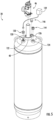
- FIG. 1 shows a fire suppression storage device 20 including a tank 22.
- the exemplary tank 22 has a body 24 including a cylindrical centerbody section 26 defining a central longitudinal axis 500. In an exemplary installation situation, the axis 500 is vertical.
- the tank 22 has respective upper and lower domed end portions 28 and 30.
- Exemplary tank materials are metal (e.g., steel or aluminum alloy) and the tank may represent any of numerous existing or yet-developed tank configurations.
- the tank has an interior 32 which, in pre-discharge condition, contains a body of liquid suppressant (agent) shown having a surface 34 leaving a headspace 36 thereabove to contain compressed gas pressurant/propellant.
- the upper end portion 28 bears a center port surrounded by a fitting 40 (e.g., internally-threaded or externally-threaded).
- the exemplary fitting 40 receives a lower externally threaded portion 42 of a body 44 of a discharge valve assembly 46 having a discharge valve 48.
- the discharge valve assembly 46 combines with a discharge conduit (e.g., a metal tube) 50 to form a discharge assembly.
- Exemplary suppressants are HFCs or non HFC agents such as FK-5-1-12 mentioned above.
- Suppressants may broadly include “clean agents” and aqueous agents.
- a “clean agent” is defined as an "electrically nonconductive, volatile, or gaseous fire extinguishant that does not leave a residue upon evaporation.”
- cleaning agents include halocarbons (haloalkanes, haloketones, haloacids and the like) and their blends.
- Specific examples include fuoroform (HFC-23), bromotrifluoromethane (Freon 13B1), trifluoroiodomethane (Freon 13T1), pentafluoroethane (HFC-125), 1,1,1,2,3,3,3-heptafluoropropane (HFC-227ea), and the like.
- Exemplary pressurant/propellant is N 2 , argon (Ar), carbon dioxide (CO 2 ), or blends.
- the exemplary discharge conduit 50 extends from an upper end 52 to a lower end 54.
- An exemplary portion 56 adjacent the upper end 52 is externally threaded and received in an internally threaded bore of the discharge valve body lower portion 42.
- the lower end 54 is well below the liquid surface 34 ( FIG. 1 ) so that pressure in the headspace 36 ( FIG. 1 ) will drive suppressant upward through the discharge tube if the discharge valve is open.
- the discharge conduit axis 502 ( FIGS. 1-4 ) is coincident with the tank axis 500.
- FIG. 2 shows a liquid level sensing gauge 80 on the discharge conduit 50.
- the exemplary gauge 80 may be a capacitive gauge whose capacitance is affected by the presence of surrounding liquid.
- the exemplary gauge 80 is positioned on/along the conduit 50 exterior or outer diameter (OD) surface 58 (diameter D) running generally longitudinally.
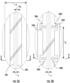
- the gauge 80 comprises two main conductors shown as traces 82A, 82B ( FIG. 2A ).
- the exemplary traces are parallel, each having a length L T and a width W T ( FIG. 2A ) and having a spacing S ( FIG.
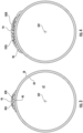
- FIG. 3 shows the traces 82A, 82B on the OD surface 58 of the conduit 50.
- An interior or inner diameter (ID) surface 60 is also shown surrounding an interior 62 of the conduit.
- the exemplary traces 82A, 82B may be applied in situ via an additive manufacturing technique (e.g., 3D printing such as spraying (e.g., of metallic particles in a jet or aerosol jet), screen printing (e.g., using a screen and stencil), or paste (e.g., metallic particles in an aqueous or organic medium) extrusion (under pressure through a nozzle)).
- additive manufacturing technique e.g., 3D printing such as spraying (e.g., of metallic particles in a jet or aerosol jet), screen printing (e.g., using a screen and stencil), or paste (e.g., metallic particles in an aqueous or organic medium) extrusion (under pressure through a nozzle)).
- Exemplary metals for the traces include copper, silver, nickel, gold and alloys including such metals.
- An initial such application step may be followed by a hardening (e.g., drying or curing step).
- the conduit is treated by heat above room or standard temperature.
- Exemplary heating may be via infrared (IR).
- Other curing may involve ultraviolet irradiation or plasma treatment.
- individual layers or subgroups of layers are so dried or cured before applying subsequent layers or groups, and so forth.
- the heating or curing occurs only after all layers are applied.
- the gauge or trace 80 (82A, 82B - FIG. 2A ) length L T is 800 mm
- the trace width W T ( FIG. 2A ) is 0.5 mm
- the trace spacing S is 0.1 mm.
- the length L T is dictated by the length of the discharge conduit 50, which can range from 10 mm to 2000 mm, more typically 250 mm to 2000 mm.
- the length L T will be at least 25% of a height of the tank interior (e.g., 15% to 100% or 25% to 95%).
- the width W T of the traces 82A, 82B may be influenced by the spray technique and may range from 0.01 mm to 20 mm or 0.01 to 2.0 mm or 0.10 mm to 1.0 mm.
- the minimum spacing is influenced by deposition technique. During the printing, overspray and fluctuations on the surface may result in the traces having local variations in the spacing. It is undesirable to have the two parallel traces 82A, 82B touch, so nominal spacing S (and associated on-center spacing S+W T ) may be selected to reduce the likelihood of the two traces touching.
- An exemplary spacing S is 0.1 mm, more broadly 0.05 mm to 1.0 mm or 0.01 mm to 3.0 mm depending on printing technique.
- an electrically insulative base layer 90 ( FIG. 3 ) may be applied in the region of the OD surface 58 to be occupied by the gauge 80.
- the exemplary layer 90 may be a polymeric material such as a polyimide although other suitable insulative material may also be used such as glass or ceramic material. This may be applied (formed) in situ by a process such as spraying (e.g., as noted above for the conductors). Alternatively, a tape pre-form (e.g., adhesive-backed) may be used.
- the traces 82A, 82B may be applied. Thereafter, leads 92A, 92B ( FIG. 2 ) may be electrically connected to the traces such as by gluing via electrically conductive paste (time cured, heat cured, or UV cured) or soldering or welding. Thereafter, an encapsulating insulative layer (encapsulant) 94 ( FIG. 3 - e.g., also polymeric such as polyimide or other suitable insulative material such as glass or ceramic material) may be applied over the traces 82A, 82B to protect them from the liquid suppressant (e.g., via the same or similar in situ technique).
- encapsulant e.g., also polymeric such as polyimide or other suitable insulative material such as glass or ceramic material
- the exemplary encapsulant 94 prevents any suppressant from coming directly between the traces 82A and 82B. Nevertheless, the presence of suppressant along the outer surface of the encapsulant laterally away from the immediate gap between traces still allows capacitive measurement via a fringe effect. Fringe field lines between the traces will pass outward through either the liquid or empty space in the vessel (tank). Thus, the presence of liquid versus empty space affects capacitive behavior and thus allows for measurement of liquid level.
- an electronics module may be mounted to the discharge conduit and may include a battery for providing the necessary power.
- the electronics module may further include a radio communicating over a protocol (e.g., Bluetooth, WiFi, ZigBee, or other suitable protocol), infrared, or optical communication to communicate with an external device.
- a protocol e.g., Bluetooth, WiFi, ZigBee, or other suitable protocol
- the leads 92A, 92B pass electrical stimulus to and from outside of the tank.
- the leads may pass to a connector 120 ( FIG. 2 ) with contacts complementary to those of an additional connector 130 ( FIG. 5 ) that mounts to one of the ports to also act as a closure for such port.
- FIG. 2 a connector 120 ( FIG. 2 ) with contacts complementary to those of an additional connector 130 ( FIG. 5 ) that mounts to one of the ports to also act as a closure for such port.
- the port 122 may instead include a connector 130 having lower contacts for mating with those of the connector 120 and upper contacts for mating with wiring to an electronics module 132 (e.g., mounted to the discharge valve body).
- the liquid level measurement assembly may be separate from the discharge tube 50.
- the gauge 80 traces 82A, 82B may be on an elongate substrate such as a tube or rod separate from the discharge tube.
- the separate gauge traces may be applied to the tube or rod by similar techniques to applying to the discharge tube. That separate tube or rod may be passed through one of the spare ports (e.g., 122 after removing a baseline plug or cap) and secured thereto (e.g. a complementary fitting to fitting 122 mounting the proximal end of the tube or rod).
- the connector 120 may be integral with or separate from that fitting.
- the liquid level measurement assembly may include the substrate, the traces 82A, 82B, the leads 92A, 92B, the fitting, and the encapsulant 94.
- Exemplary tubes are metallic or non-metallic tubes with closed or open lower ends.
- Exemplary rods are metallic or non-metallic. Tube or rod length and gauge length may be as discussed for the gauge 80 on the discharge tube 50.
- the separate assembly may allow the lower end of the rod or tube to go all the way to the tank bottom or otherwise closer than the lower end of the discharge tube.
- Such a liquid level measurement assembly may be used to retrofit an existing tank without need to remove the discharge tube.
- the insulative base layer 90 between the traces and substrate may be omitted.
- Such a separate liquid level measurement assembly may be used, for example, in retrofits such as field retrofit of a remote driver system where the baseline plug can be removed from the fitting 122 and the assembly installed in its place while the tank is full of suppressant.
- FIG. 5 also shows respective plugs 144 and 146 with the ports 124 and 126. These might respectively be re-fill ports, overpressure devices such as rupture disks or relief valves, auxiliary pressure gauges and the like. In alternative situations where an external pressurant/propellant is used (e.g., an external N 2 "driver" tank), one of the ports may couple to the driver tank or the driver tank may couple to the valve assembly.
- an external pressurant/propellant e.g., an external N 2 "driver" tank
- one of the ports may couple to the driver tank or the driver tank may couple to the valve assembly.
- the electronics module 132 may apply an alternating current (AC) signal across the gauge 80 and measure the resistance and capacitance. From these measurements, the module determines the liquid level. As liquid level increases and more of the gauge 80 is exposed to liquid, the effective capacitance decreases. This gives rise to many ways to use capacitance in the level measurement.
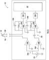
- One example involves the module 132 ( FIG. 6 ) having a reference capacitor 320. Relative behavior of the gauge 80 and reference capacitor may then be used.
- a processor 322 may be programmed with a relationship between that relative behavior and fluid level (whether characterized as level or mass or volume or percentage). The processor 322 may display (via LCD, LED, or the like) the resulting liquid level or communicate it (e.g., via radio, infrared, optical, or hardwiring) to additional control and monitoring equipment.
- Calibration would typically be necessary to determine gauge capacitance because nominally identical gauges may demonstrate a range of empty capacitance, for example, of 6000nF to 1000nF.
- a 60 cm long gauge 80 with an AC signal of one volt in amplitude and 10 Hz in frequency may have a capacitance about 6000nF when empty and about 7200nF when full of agent.
- the delta of 1200nF equates to a capacitance change of 20nF/cm of immersion.
- a range of 5 Hz to 1000 Hz or 1 Hz to 1000 Hz may be preferred; above 10 kHz sensitivity may drop; and near 1Hz the signal may be too noisy.
- Changing voltage may affect the desirability of a frequency range, with higher voltage increasing field strength. Increased field strength will extend the fields radially outward into the liquid (below surface) or gas (above surface) increasing sensitivity and allowing higher frequencies to reduce noise. Thus, voltage and frequency may be traded off to trade-off between sensitivity and noise. In one example, a one volt, 10 Hz signal may be preferred. The upper end of the voltage range is limited by the breakdown voltage of the capacitor. Exemplary voltage ranges may be 0.1 V to 20 V or 0.5 V to 20 V.
- the tank, sensor, gauges and electronics are exposed to electromagnetic interference (EMI) that may be accounted for in order to increase accuracy of a reading taken by a liquid level sensing gauge 80.
- EMI electromagnetic interference
- the modified Wheatstone bridge illustrated in FIG. 6 is known to reduce noise in electronic circuits by balancing component values by subtracting EMI signals from two electronic components.
- the selection of frequency is also chosen based on the predicted source of EMI. In the case of an industrial application, 60-120 Hz EMI is generated by motors and power lines. So it is desirable to not include a range of frequencies needed for detection. As an example, a scan from 1 Hz to 1000 Hz may be preferred; but 60-120 Hz is omitted because of the noise level associated with conducted EMI.
- the choice in exact frequencies can be done at commissioning based on a commissioning algorithm that sweeps the frequency range of interest and selects frequencies based on the measured standard deviation of a signal.
- a function generator 324 may generate a predetermined AC signal.
- An exemplary AC signal is one volt in amplitude and 10 Hz in frequency as noted above.
- the function generator may include a power source (e.g., battery) and conventional AC signal generator circuitry (not shown).
- the output signal is split into two branch signals in two circuit branches 326A, 326B for the gauge 80 and reference capacitor 320.
- the split signal passes through an operational amplifier 328A, 328B (serving as buffer amplifiers) and then the respective gauge 80 and reference capacitor 320.
- the amplifiers 328A, 328B take the signals in and then push them through the gauge 80 and the reference capacitor 320 making sure the two capacitors will not interfere with one another. Once the split signals pass through the gauge 80 and the reference capacitor 320 they may go to a respective second operational amplifier 330A, 330B.
- Each second operational amplifier 330A, 330B amplifies the signal and filters it via a low pass filter.
- the low pass filter is provided by a respective capacitor 340A, 340B to filter out any high frequency noise and allow all low frequency signal to pass through.
- Amplification is achieved via the resistance of a resistor 342A, 342B in parallel with respective capacitor 340A, 340B. The resistance value of each resistor 342A, 342B will change the amplification value.
- the second operational amplifiers 330A, 330B When the signal exits the second operational amplifiers 330A, 330B this will be as an analog "signal one" (sensing signal) from the gauge 80 (exiting operational amplifier 330A) and an analog “signal two” (reference signal) from the reference capacitor 320 (exiting operational amplifier 330B). These may be converted to a digital sensing signal and digital reference signal, respectively, by analog-to-digital converters 350A, 350B.
- the processor 322 When the liquid level changes, the processor 322 will see the sensing signal (from converter 350A) change with respect to the reference signal (from converter 350B) in relation to how much liquid is in contact with the gauge 80.
- the processor 322 may be configured via hardwiring or programming to take the difference between those two signals to determine the liquid level.
- the reference capacitor 320 may be selected prior to manufacture of the system.
- the relative capacitance of the gauge 80 and reference capacitor 320 may be set in any of several ways. This might depend on the particular measuring situation. Detecting levels near empty may be important such as when a control system has to change the source of suppression agent over form one tank that is nearing empty to a fresh tank to maintain suppression or maintain a sustained inerting condition. For such in-use change-over purposes, one might prioritize precision near empty. Thus, one could select the capacitance of the reference capacitor 320 to match the sensing signal one and the reference signal where the most precise reading is desired.
- relative capacitance of the gauge 80 and reference capacitor 320 may be set to be identical when the gauge 80 has no liquid exposure. Thus the signals would be identical with no liquid adjacent to gauge 80.
- the relative capacitance may be selected for precision near full fill level, if detecting leaks from a tank that is supposed to be full is a primary concern. To achieve the most precise reading when the tank is full, capacitance may be selected to match the sensing signal and the reference signal when the liquid level is full. Different implementations may prioritize measurement at different locations (heights along the gauge and thus fill levels).
- Calibration to determine gauge capacitance may be carried out as follows.
- an initialization is performed on an empty tank to acquire a baseline (relationship in the example above).
- This initialization calibrates the particular gauge to the particular tank/suppressant.
- the calibration addresses manufacturing variation in the gauge. This may typically be done in the factory. For example, the signal difference is measured empty.
- the tank is filled to acquire calibration. For example, the tank may be filled with a fixed amount of suppressant and a second calibration point established.
- the fixed amount may be lower than the typical end use amount. In many situations, a given size tank is ultimately filled with a specific amount required by the end user.
- the calibration amount may be the minimum amount used by the domain of users.
- the relative signal properties at this calibration amount and the empty baseline may be used to program the processor 322 with a linear relationship from which flow level may be determined for other relative capacitance measurements associated with other levels.
- the tank may be further filled to the final end use amount.
- a further measurement may be taken in the factory. If there is departure from the relationship determined previously, the relationship may be reprogrammed in the processor 322.
- FIGS. 2B and 4 show a variation of the embodiments shown in FIGs. 2A and 3 wherein at specific intervals each axial trace 82A, 82B has a group 180A, 180B of circumferentially-extending branch traces 182A, 182B extending away from the other conductor. These groups have an on-center spacing L B .
- traces 182A, 182B act to increase the capacitance between traces 82A and 82B facilitating higher signal to noise ratio and ultimately contributing to better sensor resolution.
- FIG. 4 in the variation shown in FIGS.
- the widths of the insulative base layer 90 and the encapsulating insulative layer (encapsulant) 94 may be increased to accommodate the circumferentially-extending branch traces 182A, 182B.
- the embodiments of FIGs. 2B and 4 are otherwise similar to the embodiments of FIGs. 2A and 3 with respect to the elements described above.
- the fire suppression storage device may have one or more advantages over various alternatives. Some advantages may be cost relative to systems that use floats, because the float tube assembly is eliminated. Other advantages may involve ease of servicing (e.g., by merely replacing a discharge conduit rather than a more complex assembly). Other advantages may be reliability in that there are no moving parts to wear.
- first, second, and the like in the description and following claims is for differentiation within the claim only and does not necessarily indicate relative or absolute importance or temporal order. Similarly, the identification in a claim of one element as “first” (or the like) does not preclude such "first” element from identifying an element that is referred to as “second” (or the like) in another claim or in the description.
Landscapes
- Physics & Mathematics (AREA)
- Engineering & Computer Science (AREA)
- Power Engineering (AREA)
- Health & Medical Sciences (AREA)
- Public Health (AREA)
- Business, Economics & Management (AREA)
- Emergency Management (AREA)
- Electromagnetism (AREA)
- Thermal Sciences (AREA)
- Fluid Mechanics (AREA)
- General Physics & Mathematics (AREA)
- Measurement Of Levels Of Liquids Or Fluent Solid Materials (AREA)
Claims (15)
- Verfahren zum Herstellen einer Feuerlöschmittelablassanordnung, wobei die Ablassanordnung Folgendes umfasst:ein Ablassventil (48); undeine Ablassleitung (50), die Folgendes aufweist:eine Innenfläche (60); undeine Außenfläche (58),wobei das Verfahren Folgendes umfasst:
Bilden vor Ort eines ersten Leiters (82A) und eines zweiten Leiters (82B) eines kapazitiven Messgeräts (80) auf der Ablassleitung. - Verfahren nach Anspruch 1, wobei:
der erste Leiter (82A) und der zweite Leiter (82B) entlang der Außenfläche aufgebracht werden. - Verfahren nach Anspruch 1 oder Anspruch 2, ferner umfassend:vor dem Bilden vor Ort des ersten Leiters und des zweiten Leiters, Bilden vor Ort einer ersten isolierenden Schicht (90) auf der Ablassleitung; undnach dem Bilden vor Ort des ersten Leiters und des zweiten Leiters, Bilden vor Ort einer zweiten isolierenden Schicht (94) über dem ersten Leiter, dem zweiten Leiter und der ersten isolierenden Schicht.
- Verfahren nach Anspruch 3, wobei die erste und die zweite isolierende Schicht Polymerschichten sind.
- Verfahren nach Anspruch 3, wobei die erste und die zweite isolierende Schicht ein Polyimid umfassen.
- Verfahren nach einem der Ansprüche 3 bis 5, wobei die zweite isolierende Schicht verhindert, dass ein Löschmittel direkt zwischen den ersten Leiter und den zweiten Leiter gelangt.
- Verfahren nach einem der vorherigen Ansprüche, wobei:
das Bilden vor Ort des ersten Leiters und des zweiten Leiters Sprühen umfasst. - Verfahren nach einem der vorherigen Ansprüche, ferner umfassend:
Verbinden einer jeweiligen ersten und zweiten Zuleitung (92A, 92B) mit dem ersten und dem zweiten Leiter durch Leitpaste. - Verfahren nach einem der vorherigen Ansprüche, wobei:
der erste Leiter (82A) und der zweite Leiter (82B) parallel sind. - Verfahren nach einem der vorherigen Ansprüche, wobei:
der erste Leiter (82A) und der zweite Leiter (82B) eine Breite (WT) von 0,1 mm bis 1,0 mm aufweisen. - Verfahren nach einem der vorherigen Ansprüche, wobei:
der erste Leiter (82A) und der zweite Leiter (82B) parallel sind und um 0,05 mm bis 1,0 mm beabstandet sind. - Verfahren nach einem der vorherigen Ansprüche, ferner umfassend:
Montieren der Ablassleitung an einer Gewindeöffnung (40) eines Tanks. - Verfahren nach Anspruch 12, wobei:sich die erste Zuleitung (92A) und die zweite Zuleitung (92B) von dem Messgerät zu einem Steckverbinder erstrecken;der Tank eine zweite Öffnung (112) aufweist; undein zusätzlicher Steckverbinder (130) einen Verschluss bildet, der die zweite Öffnung abdichtet und auf den Steckverbinder abgestimmt ist.
- Verfahren nach Anspruch 13, wobei es sich um eine Nachrüstung eines Systems mit einem Füllstandserfassungsrohr, das an der zweiten Öffnung (122) montiert ist, handelt.
- Verfahren nach einem der Ansprüche 12 bis 14, ferner umfassend:
Füllen des Tanks mit einem Halogenkohlenwasserstofflöschmittel.
Applications Claiming Priority (3)
| Application Number | Priority Date | Filing Date | Title |
|---|---|---|---|
| US201862773260P | 2018-11-30 | 2018-11-30 | |
| PCT/US2019/053070 WO2020112227A1 (en) | 2018-11-30 | 2019-09-26 | Printed capacitive liquid level sensor for fire suppression |
| EP19783919.4A EP3679332B1 (de) | 2018-11-30 | 2019-09-26 | Gedruckter kapazitiver füllstandssensor für feuerunterdrückung |
Related Parent Applications (2)
| Application Number | Title | Priority Date | Filing Date |
|---|---|---|---|
| EP19783919.4A Division EP3679332B1 (de) | 2018-11-30 | 2019-09-26 | Gedruckter kapazitiver füllstandssensor für feuerunterdrückung |
| EP19783919.4A Division-Into EP3679332B1 (de) | 2018-11-30 | 2019-09-26 | Gedruckter kapazitiver füllstandssensor für feuerunterdrückung |
Publications (2)
| Publication Number | Publication Date |
|---|---|
| EP4148398A1 EP4148398A1 (de) | 2023-03-15 |
| EP4148398B1 true EP4148398B1 (de) | 2025-01-01 |
Family
ID=68165859
Family Applications (2)
| Application Number | Title | Priority Date | Filing Date |
|---|---|---|---|
| EP22202271.7A Active EP4148398B1 (de) | 2018-11-30 | 2019-09-26 | Gedruckter kapazitiver flüssigkeitspegelsensor zur brandunterdrückung |
| EP19783919.4A Active EP3679332B1 (de) | 2018-11-30 | 2019-09-26 | Gedruckter kapazitiver füllstandssensor für feuerunterdrückung |
Family Applications After (1)
| Application Number | Title | Priority Date | Filing Date |
|---|---|---|---|
| EP19783919.4A Active EP3679332B1 (de) | 2018-11-30 | 2019-09-26 | Gedruckter kapazitiver füllstandssensor für feuerunterdrückung |
Country Status (4)
| Country | Link |
|---|---|
| US (1) | US11944857B2 (de) |
| EP (2) | EP4148398B1 (de) |
| ES (1) | ES3008586T3 (de) |
| WO (1) | WO2020112227A1 (de) |
Families Citing this family (3)
| Publication number | Priority date | Publication date | Assignee | Title |
|---|---|---|---|---|
| RU2751530C1 (ru) * | 2020-10-19 | 2021-07-14 | Акционерное общество "ИСТОЧНИК ПЛЮС" | Модуль пожаротушения |
| RU2768836C1 (ru) * | 2021-06-07 | 2022-03-24 | Акционерное общество "ИСТОЧНИК ПЛЮС" | Модуль пожаротушения пеной высокой кратности |
| EP4230971A1 (de) * | 2022-02-20 | 2023-08-23 | Hexagon Ragasco AS | Intelligentes verbunddruckgefäss |
Citations (1)
| Publication number | Priority date | Publication date | Assignee | Title |
|---|---|---|---|---|
| DE19520799A1 (de) * | 1995-06-07 | 1996-12-12 | Siemens Ag | Verfahren zur Überwachung des Füllstands von Lösch- oder Treibmitteln |
Family Cites Families (27)
| Publication number | Priority date | Publication date | Assignee | Title |
|---|---|---|---|---|
| US2999230A (en) * | 1959-07-21 | 1961-09-05 | American District Telegraph Co | Liquid level supervisory device |
| GB1389015A (en) * | 1971-08-24 | 1975-04-03 | Kidde & Co Walter | Radio active level indicator |
| US4280126A (en) * | 1979-05-14 | 1981-07-21 | Chemetron Corporation | Liquid level detector |
| US4384486A (en) | 1981-03-09 | 1983-05-24 | General Fire Extinguisher Corporation | Fill indicator for fire extinguishing systems |
| GB8308129D0 (en) | 1983-03-24 | 1983-05-05 | Ici Plc | Liquid level measurement |
| DE3731793A1 (de) | 1987-09-22 | 1989-03-30 | Total Feuerschutz Gmbh | Feuerloeschanlage |
| US5481197A (en) | 1993-09-17 | 1996-01-02 | Penberthy, Inc. | High pressure, leak resistant explosionproof capacitance probe |
| US5698269A (en) * | 1995-12-20 | 1997-12-16 | Ppg Industries, Inc. | Electrostatic deposition of charged coating particles onto a dielectric substrate |
| US6490920B1 (en) | 1997-08-25 | 2002-12-10 | Millennium Sensors Ltd. | Compensated capacitive liquid level sensor |
| LU90629B1 (de) * | 2000-08-10 | 2006-02-21 | Luxembourg Patent Co | Vorrichtung zum Feststellen eines Gasverlustes auseinem Kohlendioxid-Druckbeh{lter. |
| DE10231946A1 (de) | 2002-07-15 | 2004-01-29 | Exess Engineering Gmbh | Verfahren zur Messung des Füllstandes eines Fluids in einem Behälter und entsprechender Füllstandssensor |
| US6857313B2 (en) | 2003-03-31 | 2005-02-22 | Rochester Gauges, Inc. | Self-calibrating capacitance gauge |
| FR2892509B1 (fr) | 2005-10-26 | 2007-12-21 | Inergy Automotive Systems Res | Jauge capacitive pour reservoir a carburant |
| PL1884757T3 (pl) | 2006-08-02 | 2014-04-30 | Air Prod & Chem | Sposób i urządzenie do monitorowania ciśnienia płynu |
| DE102006048015B4 (de) | 2006-10-09 | 2015-01-29 | Minimax Gmbh & Co. Kg | Feuerlöschanlage für ein Gehäuse |
| DE102008031647A1 (de) * | 2008-07-04 | 2010-02-04 | Continental Automotive Gmbh | Füllstandssensor und System mit einem Füllstandssensor und einem Fluidreservoir |
| DE102009030674A1 (de) * | 2009-06-26 | 2010-12-30 | Emitec Gesellschaft Für Emissionstechnologie Mbh | Entnahmerohr für einen Tank und Verfahren zu dessen Herstellung |
| KR100962022B1 (ko) * | 2010-01-12 | 2010-06-08 | (주) 유니크코리아엔아이 | 정전용량형 압력센서 및 그 제조방법 |
| FI125873B (fi) | 2011-01-26 | 2016-03-15 | Marioff Corp Oy | Menetelmä ja laitteisto palontorjuntalaitteiston sammutusnestesäiliön nestemäärän tarkkailemiseksi |
| US9302128B2 (en) | 2011-10-25 | 2016-04-05 | Kidde Technologies, Inc. | Automatic fire extinguishing system with internal dip tube |
| KR20130099300A (ko) | 2012-02-29 | 2013-09-06 | (주)유민에쓰티 | 정전용량형 수위감지센서 |
| DE102013005963B4 (de) | 2013-04-09 | 2026-04-16 | Balluff Gmbh | Kapazitiver Füllstandssensor |
| JP6509900B2 (ja) * | 2014-03-28 | 2019-05-08 | ファーベル・インダストリエ・エス.ピー.エー.Faber Industrie S.P.A. | 複合材料の圧力容器、並びに、容器を制御するためのシリンダー及び方法 |
| CN204563401U (zh) | 2015-04-08 | 2015-08-19 | 上海磊诺安防技术股份有限公司 | 一种具有射频导纳液位计的七氟丙烷灭火装置 |
| JP6918702B2 (ja) * | 2015-04-16 | 2021-08-11 | サノフィ−アベンティス・ドイチュラント・ゲゼルシャフト・ミット・ベシュレンクテル・ハフツング | 充填レベルの容量判定のためのセンサおよびセンサアセンブリ |
| CN105675092A (zh) | 2016-03-04 | 2016-06-15 | 温州瓯云科技有限公司 | 一种微型高精度液位传感器 |
| CN205373827U (zh) | 2016-03-04 | 2016-07-06 | 温州瓯云科技有限公司 | 一种微型高精度液位传感器 |
-
2019
- 2019-09-26 US US17/254,944 patent/US11944857B2/en active Active
- 2019-09-26 EP EP22202271.7A patent/EP4148398B1/de active Active
- 2019-09-26 ES ES22202271T patent/ES3008586T3/es active Active
- 2019-09-26 EP EP19783919.4A patent/EP3679332B1/de active Active
- 2019-09-26 WO PCT/US2019/053070 patent/WO2020112227A1/en not_active Ceased
Patent Citations (1)
| Publication number | Priority date | Publication date | Assignee | Title |
|---|---|---|---|---|
| DE19520799A1 (de) * | 1995-06-07 | 1996-12-12 | Siemens Ag | Verfahren zur Überwachung des Füllstands von Lösch- oder Treibmitteln |
Also Published As
| Publication number | Publication date |
|---|---|
| US11944857B2 (en) | 2024-04-02 |
| EP4148398A1 (de) | 2023-03-15 |
| ES3008586T3 (en) | 2025-03-24 |
| WO2020112227A1 (en) | 2020-06-04 |
| US20210283447A1 (en) | 2021-09-16 |
| EP3679332B1 (de) | 2022-11-23 |
| EP3679332A1 (de) | 2020-07-15 |
Similar Documents
| Publication | Publication Date | Title |
|---|---|---|
| EP4148398B1 (de) | Gedruckter kapazitiver flüssigkeitspegelsensor zur brandunterdrückung | |
| JP4751007B2 (ja) | 二酸化炭素消火装置 | |
| CN103430016B (zh) | 用于校准导电性测量单元的方法 | |
| US20210275850A1 (en) | Magnetic Trap Suppression Tank Level Sensor | |
| JPH0244375B2 (de) | ||
| DE3731793A1 (de) | Feuerloeschanlage | |
| US8598883B2 (en) | Measuring device of the electric properties of solid or liquid geological samples | |
| US4671110A (en) | Level sensing device | |
| US11986686B2 (en) | Adaptable suppression tank level sensor | |
| RU2579542C2 (ru) | Измеритель уровня жидкости | |
| US20200339324A1 (en) | Head for a storage container for liquids | |
| US11435249B2 (en) | Electrostatic discharge resistant pressure sensor | |
| CN212118864U (zh) | 一种消防灭火液的测量传感器 | |
| US2427291A (en) | Vapor detector | |
| RS59623B1 (sr) | Merna sonda za detektovanje najmanje jedne izmerene vrednosti tečnosti | |
| RU2515074C1 (ru) | Устройство для измерения массы двухфазного вещества в замкнутом цилиндрическом резервуаре | |
| JP2016212985A (ja) | 絶縁構造体、絶縁構造体のリーク検査方法及びシーズヒータ | |
| Boboc | Modern Systems for Control and Extinguishing Fires at Petroleum Storage Tanks. | |
| HK40035646A (en) | Head for a storage container for liquids | |
| NL8403350A (nl) | Meetwaardegever. |
Legal Events
| Date | Code | Title | Description |
|---|---|---|---|
| PUAI | Public reference made under article 153(3) epc to a published international application that has entered the european phase |
Free format text: ORIGINAL CODE: 0009012 |
|
| STAA | Information on the status of an ep patent application or granted ep patent |
Free format text: STATUS: THE APPLICATION HAS BEEN PUBLISHED |
|
| AC | Divisional application: reference to earlier application |
Ref document number: 3679332 Country of ref document: EP Kind code of ref document: P |
|
| AK | Designated contracting states |
Kind code of ref document: A1 Designated state(s): AL AT BE BG CH CY CZ DE DK EE ES FI FR GB GR HR HU IE IS IT LI LT LU LV MC MK MT NL NO PL PT RO RS SE SI SK SM TR |
|
| STAA | Information on the status of an ep patent application or granted ep patent |
Free format text: STATUS: REQUEST FOR EXAMINATION WAS MADE |
|
| 17P | Request for examination filed |
Effective date: 20230915 |
|
| RBV | Designated contracting states (corrected) |
Designated state(s): AL AT BE BG CH CY CZ DE DK EE ES FI FR GB GR HR HU IE IS IT LI LT LU LV MC MK MT NL NO PL PT RO RS SE SI SK SM TR |
|
| GRAP | Despatch of communication of intention to grant a patent |
Free format text: ORIGINAL CODE: EPIDOSNIGR1 |
|
| STAA | Information on the status of an ep patent application or granted ep patent |
Free format text: STATUS: GRANT OF PATENT IS INTENDED |
|
| INTG | Intention to grant announced |
Effective date: 20240621 |
|
| RAP1 | Party data changed (applicant data changed or rights of an application transferred) |
Owner name: KIDDE-FENWAL, LLC |
|
| GRAS | Grant fee paid |
Free format text: ORIGINAL CODE: EPIDOSNIGR3 |
|
| P01 | Opt-out of the competence of the unified patent court (upc) registered |
Free format text: CASE NUMBER: APP_54659/2024 Effective date: 20241004 |
|
| GRAA | (expected) grant |
Free format text: ORIGINAL CODE: 0009210 |
|
| STAA | Information on the status of an ep patent application or granted ep patent |
Free format text: STATUS: THE PATENT HAS BEEN GRANTED |
|
| AC | Divisional application: reference to earlier application |
Ref document number: 3679332 Country of ref document: EP Kind code of ref document: P |
|
| AK | Designated contracting states |
Kind code of ref document: B1 Designated state(s): AL AT BE BG CH CY CZ DE DK EE ES FI FR GB GR HR HU IE IS IT LI LT LU LV MC MK MT NL NO PL PT RO RS SE SI SK SM TR |
|
| REG | Reference to a national code |
Ref country code: GB Ref legal event code: FG4D |
|
| REG | Reference to a national code |
Ref country code: DE Ref legal event code: R096 Ref document number: 602019064502 Country of ref document: DE |
|
| REG | Reference to a national code |
Ref country code: CH Ref legal event code: EP |
|
| REG | Reference to a national code |
Ref country code: IE Ref legal event code: FG4D |
|
| REG | Reference to a national code |
Ref country code: ES Ref legal event code: FG2A Ref document number: 3008586 Country of ref document: ES Kind code of ref document: T3 Effective date: 20250324 |
|
| REG | Reference to a national code |
Ref country code: LT Ref legal event code: MG9D |
|
| REG | Reference to a national code |
Ref country code: NL Ref legal event code: MP Effective date: 20250101 |
|
| REG | Reference to a national code |
Ref country code: AT Ref legal event code: MK05 Ref document number: 1756662 Country of ref document: AT Kind code of ref document: T Effective date: 20250101 |
|
| PG25 | Lapsed in a contracting state [announced via postgrant information from national office to epo] |
Ref country code: NL Free format text: LAPSE BECAUSE OF FAILURE TO SUBMIT A TRANSLATION OF THE DESCRIPTION OR TO PAY THE FEE WITHIN THE PRESCRIBED TIME-LIMIT Effective date: 20250101 |
|
| PG25 | Lapsed in a contracting state [announced via postgrant information from national office to epo] |
Ref country code: FI Free format text: LAPSE BECAUSE OF FAILURE TO SUBMIT A TRANSLATION OF THE DESCRIPTION OR TO PAY THE FEE WITHIN THE PRESCRIBED TIME-LIMIT Effective date: 20250101 |
|
| PG25 | Lapsed in a contracting state [announced via postgrant information from national office to epo] |
Ref country code: PL Free format text: LAPSE BECAUSE OF FAILURE TO SUBMIT A TRANSLATION OF THE DESCRIPTION OR TO PAY THE FEE WITHIN THE PRESCRIBED TIME-LIMIT Effective date: 20250101 |
|
| PG25 | Lapsed in a contracting state [announced via postgrant information from national office to epo] |
Ref country code: IS Free format text: LAPSE BECAUSE OF FAILURE TO SUBMIT A TRANSLATION OF THE DESCRIPTION OR TO PAY THE FEE WITHIN THE PRESCRIBED TIME-LIMIT Effective date: 20250501 Ref country code: NO Free format text: LAPSE BECAUSE OF FAILURE TO SUBMIT A TRANSLATION OF THE DESCRIPTION OR TO PAY THE FEE WITHIN THE PRESCRIBED TIME-LIMIT Effective date: 20250401 |
|
| PG25 | Lapsed in a contracting state [announced via postgrant information from national office to epo] |
Ref country code: HR Free format text: LAPSE BECAUSE OF FAILURE TO SUBMIT A TRANSLATION OF THE DESCRIPTION OR TO PAY THE FEE WITHIN THE PRESCRIBED TIME-LIMIT Effective date: 20250101 |
|
| PG25 | Lapsed in a contracting state [announced via postgrant information from national office to epo] |
Ref country code: LV Free format text: LAPSE BECAUSE OF FAILURE TO SUBMIT A TRANSLATION OF THE DESCRIPTION OR TO PAY THE FEE WITHIN THE PRESCRIBED TIME-LIMIT Effective date: 20250101 Ref country code: PT Free format text: LAPSE BECAUSE OF FAILURE TO SUBMIT A TRANSLATION OF THE DESCRIPTION OR TO PAY THE FEE WITHIN THE PRESCRIBED TIME-LIMIT Effective date: 20250502 |
|
| PG25 | Lapsed in a contracting state [announced via postgrant information from national office to epo] |
Ref country code: BG Free format text: LAPSE BECAUSE OF FAILURE TO SUBMIT A TRANSLATION OF THE DESCRIPTION OR TO PAY THE FEE WITHIN THE PRESCRIBED TIME-LIMIT Effective date: 20250101 Ref country code: GR Free format text: LAPSE BECAUSE OF FAILURE TO SUBMIT A TRANSLATION OF THE DESCRIPTION OR TO PAY THE FEE WITHIN THE PRESCRIBED TIME-LIMIT Effective date: 20250402 |
|
| PG25 | Lapsed in a contracting state [announced via postgrant information from national office to epo] |
Ref country code: AT Free format text: LAPSE BECAUSE OF FAILURE TO SUBMIT A TRANSLATION OF THE DESCRIPTION OR TO PAY THE FEE WITHIN THE PRESCRIBED TIME-LIMIT Effective date: 20250101 |
|
| PG25 | Lapsed in a contracting state [announced via postgrant information from national office to epo] |
Ref country code: CZ Free format text: LAPSE BECAUSE OF FAILURE TO SUBMIT A TRANSLATION OF THE DESCRIPTION OR TO PAY THE FEE WITHIN THE PRESCRIBED TIME-LIMIT Effective date: 20250101 |
|
| PG25 | Lapsed in a contracting state [announced via postgrant information from national office to epo] |
Ref country code: SE Free format text: LAPSE BECAUSE OF FAILURE TO SUBMIT A TRANSLATION OF THE DESCRIPTION OR TO PAY THE FEE WITHIN THE PRESCRIBED TIME-LIMIT Effective date: 20250101 |
|
| REG | Reference to a national code |
Ref country code: DE Ref legal event code: R097 Ref document number: 602019064502 Country of ref document: DE |
|
| PG25 | Lapsed in a contracting state [announced via postgrant information from national office to epo] |
Ref country code: SM Free format text: LAPSE BECAUSE OF FAILURE TO SUBMIT A TRANSLATION OF THE DESCRIPTION OR TO PAY THE FEE WITHIN THE PRESCRIBED TIME-LIMIT Effective date: 20250101 |
|
| PG25 | Lapsed in a contracting state [announced via postgrant information from national office to epo] |
Ref country code: DK Free format text: LAPSE BECAUSE OF FAILURE TO SUBMIT A TRANSLATION OF THE DESCRIPTION OR TO PAY THE FEE WITHIN THE PRESCRIBED TIME-LIMIT Effective date: 20250101 |
|
| PG25 | Lapsed in a contracting state [announced via postgrant information from national office to epo] |
Ref country code: IT Free format text: LAPSE BECAUSE OF FAILURE TO SUBMIT A TRANSLATION OF THE DESCRIPTION OR TO PAY THE FEE WITHIN THE PRESCRIBED TIME-LIMIT Effective date: 20250101 |
|
| PGFP | Annual fee paid to national office [announced via postgrant information from national office to epo] |
Ref country code: GB Payment date: 20250703 Year of fee payment: 7 |
|
| PG25 | Lapsed in a contracting state [announced via postgrant information from national office to epo] |
Ref country code: EE Free format text: LAPSE BECAUSE OF FAILURE TO SUBMIT A TRANSLATION OF THE DESCRIPTION OR TO PAY THE FEE WITHIN THE PRESCRIBED TIME-LIMIT Effective date: 20250101 |
|
| PG25 | Lapsed in a contracting state [announced via postgrant information from national office to epo] |
Ref country code: RO Free format text: LAPSE BECAUSE OF FAILURE TO SUBMIT A TRANSLATION OF THE DESCRIPTION OR TO PAY THE FEE WITHIN THE PRESCRIBED TIME-LIMIT Effective date: 20250101 |
|
| PG25 | Lapsed in a contracting state [announced via postgrant information from national office to epo] |
Ref country code: SK Free format text: LAPSE BECAUSE OF FAILURE TO SUBMIT A TRANSLATION OF THE DESCRIPTION OR TO PAY THE FEE WITHIN THE PRESCRIBED TIME-LIMIT Effective date: 20250101 |
|
| PLBE | No opposition filed within time limit |
Free format text: ORIGINAL CODE: 0009261 |
|
| STAA | Information on the status of an ep patent application or granted ep patent |
Free format text: STATUS: NO OPPOSITION FILED WITHIN TIME LIMIT |
|
| 26N | No opposition filed |
Effective date: 20251002 |
|
| PGFP | Annual fee paid to national office [announced via postgrant information from national office to epo] |
Ref country code: ES Payment date: 20251016 Year of fee payment: 7 |