EP4148359B1 - Kühlschrank - Google Patents
Kühlschrank Download PDFInfo
- Publication number
- EP4148359B1 EP4148359B1 EP22205526.1A EP22205526A EP4148359B1 EP 4148359 B1 EP4148359 B1 EP 4148359B1 EP 22205526 A EP22205526 A EP 22205526A EP 4148359 B1 EP4148359 B1 EP 4148359B1
- Authority
- EP
- European Patent Office
- Prior art keywords
- door
- refrigerator
- control unit
- opening
- panel
- Prior art date
- Legal status (The legal status is an assumption and is not a legal conclusion. Google has not performed a legal analysis and makes no representation as to the accuracy of the status listed.)
- Active
Links
Images


Classifications
-
- F—MECHANICAL ENGINEERING; LIGHTING; HEATING; WEAPONS; BLASTING
- F25—REFRIGERATION OR COOLING; COMBINED HEATING AND REFRIGERATION SYSTEMS; HEAT PUMP SYSTEMS; MANUFACTURE OR STORAGE OF ICE; LIQUEFACTION SOLIDIFICATION OF GASES
- F25D—REFRIGERATORS; COLD ROOMS; ICE-BOXES; COOLING OR FREEZING APPARATUS NOT OTHERWISE PROVIDED FOR
- F25D29/00—Arrangement or mounting of control or safety devices
- F25D29/005—Mounting of control devices
-
- F—MECHANICAL ENGINEERING; LIGHTING; HEATING; WEAPONS; BLASTING
- F25—REFRIGERATION OR COOLING; COMBINED HEATING AND REFRIGERATION SYSTEMS; HEAT PUMP SYSTEMS; MANUFACTURE OR STORAGE OF ICE; LIQUEFACTION SOLIDIFICATION OF GASES
- F25D—REFRIGERATORS; COLD ROOMS; ICE-BOXES; COOLING OR FREEZING APPARATUS NOT OTHERWISE PROVIDED FOR
- F25D23/00—General constructional features
- F25D23/02—Doors; Covers
- F25D23/025—Secondary closures
-
- F—MECHANICAL ENGINEERING; LIGHTING; HEATING; WEAPONS; BLASTING
- F25—REFRIGERATION OR COOLING; COMBINED HEATING AND REFRIGERATION SYSTEMS; HEAT PUMP SYSTEMS; MANUFACTURE OR STORAGE OF ICE; LIQUEFACTION SOLIDIFICATION OF GASES
- F25D—REFRIGERATORS; COLD ROOMS; ICE-BOXES; COOLING OR FREEZING APPARATUS NOT OTHERWISE PROVIDED FOR
- F25D23/00—General constructional features
- F25D23/06—Walls
-
- F—MECHANICAL ENGINEERING; LIGHTING; HEATING; WEAPONS; BLASTING
- F25—REFRIGERATION OR COOLING; COMBINED HEATING AND REFRIGERATION SYSTEMS; HEAT PUMP SYSTEMS; MANUFACTURE OR STORAGE OF ICE; LIQUEFACTION SOLIDIFICATION OF GASES
- F25D—REFRIGERATORS; COLD ROOMS; ICE-BOXES; COOLING OR FREEZING APPARATUS NOT OTHERWISE PROVIDED FOR
- F25D2323/00—General constructional features not provided for in other groups of this subclass
- F25D2323/02—Details of doors or covers not otherwise covered
- F25D2323/023—Door in door constructions
-
- F—MECHANICAL ENGINEERING; LIGHTING; HEATING; WEAPONS; BLASTING
- F25—REFRIGERATION OR COOLING; COMBINED HEATING AND REFRIGERATION SYSTEMS; HEAT PUMP SYSTEMS; MANUFACTURE OR STORAGE OF ICE; LIQUEFACTION SOLIDIFICATION OF GASES
- F25D—REFRIGERATORS; COLD ROOMS; ICE-BOXES; COOLING OR FREEZING APPARATUS NOT OTHERWISE PROVIDED FOR
- F25D2400/00—General features of, or devices for refrigerators, cold rooms, ice-boxes, or for cooling or freezing apparatus not covered by any other subclass
- F25D2400/06—Refrigerators with a vertical mullion
-
- F—MECHANICAL ENGINEERING; LIGHTING; HEATING; WEAPONS; BLASTING
- F25—REFRIGERATION OR COOLING; COMBINED HEATING AND REFRIGERATION SYSTEMS; HEAT PUMP SYSTEMS; MANUFACTURE OR STORAGE OF ICE; LIQUEFACTION SOLIDIFICATION OF GASES
- F25D—REFRIGERATORS; COLD ROOMS; ICE-BOXES; COOLING OR FREEZING APPARATUS NOT OTHERWISE PROVIDED FOR
- F25D2400/00—General features of, or devices for refrigerators, cold rooms, ice-boxes, or for cooling or freezing apparatus not covered by any other subclass
- F25D2400/36—Visual displays
- F25D2400/361—Interactive visual displays
Definitions
- Embodiments of the present disclosure relate to a refrigerator including an inner door including an opening and an outer door which opens and closes the opening.
- refrigerators are home appliances which each include a storage compartment for storing food and a cool air supply device to keep food fresh for a long time.
- Exemplary embodiments of refrigerators of the prior art are disclosed in US 2006/150661 A1 and US 2015/040604 A1 .
- a rack is provided in the storage compartment to put food thereon.
- the storage compartment may be provided to allow a front side thereof to be opened to put food in or take food out, and the open front side of the storage compartment may be opened and closed by a main door pivotably coupled with the body.
- a door guard capable of storing food in addition to the rack disposed in the storage compartment may be provided on a rear side of the main door.
- the door guard described above is provided at the rear side of the main door, generally, it is possible to approach the door guard by opening the main door. Meanwhile, there are refrigerators which include an additional auxiliary door provided at the main door in order to approach the door guard without opening the main door. In the case of refrigerators including the auxiliary door described above, since it is possible to approach the door guard provided at the rear side of the main door by opening only the auxiliary door, a diversity of food-storing options may increase and an effect of preserving cool air may be provided.
- a refrigerator in which a control unit which controls an internal environment of a storage compartment of the refrigerator is installed at a main door and it is possible to approach the control unit provided at the main door by opening an auxiliary door.
- the present invention defines a refrigerator according to claim 1.
- the control unit may include an operational portion and a display portion.
- the control unit may be configured to control a temperature, humidity, smell, lighting, etc. of the storage compartment.
- the control unit may include a circuit board which comprises an operational portion and a display portion, and a cover which covers the circuit board and comprises an opening which exposes a button portion operating on the operational portion and the display portion.
- the control unit may include a housing which accommodates the circuit board and the cover and is coupled with the mounting portion of the inner door.
- the control unit may include a transparent member which covers the cover and on which a function of the button portion is displayed.
- the inner door may include an upper frame, a lower frame, a left frame, and a right frame which form the opening.
- the control unit may be disposed on at least one of the upper frame, the lower frame, the left frame, and the right frame.
- the inner door may include an inner panel, an outer panel forming an interposing space with the inner panel, and an insulator foamed in the space.
- the control unit may be disposed between the inner panel and the outer panel.
- the inner panel may include an inner wall which forms the opening and supports the plurality of door guards.
- the plurality of door guards each may include a front wall, a rear wall, both side walls, a bottom, and a storage space.
- each of the plurality of door guards may form a part of a front side of the inner door.
- a control unit is provided at an inner door of a dual door, a misoperation of a user may be prevented and contaminations caused by external foreign substances, etc. may be prevented. Also, since the control unit is operated by opening only an outer door of the dual door while the inner door is closed, it is possible to reduce thermal loss of a storage compartment while the control unit is operated. Also, by having the outer door be formed overall as a transparent window or providing a transparent window which allows displaying a portion of the control unit of the inner door for externally checking, environment setting condition of the storage compartment may be checked without opening the outer door.
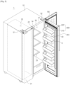
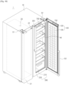
- FIG. 1 is a view of a refrigerator in a state with both an inner door and an outer door closed
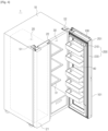
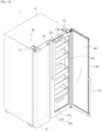
- FIG. 2 is a view illustrating a state with the inner door and the outer door of the refrigerator of FIG. 1 separately opened
- FIG. 3 is a view illustrating a state in which only the outer door of the refrigerator of FIG. 1 is opened
- FIG. 4 is a view illustrating a state with the inner door of the refrigerator of FIG. 1 is opened.
- a refrigerator 1 includes a body 10, storage compartments 20 and 30 provided inside the body 10, and a cool air supply device which supplies cool air to the storage compartments 20 and 30.
- the body 10 includes an inner casing 11 which has an approximately box shape and forms the storage compartments 20 and 30, an outer casing 12 which is coupled with an outside of the inner casing 11 and forms an exterior, and an insulator provided between the inner casing 11 and the outer casing 12.
- the inner casing 11 may be formed of a resin material
- the outer casing 12 may be formed of a metal material.
- the cool air supply device may include a compressor (not shown), a condenser (not shown), an expansion valve (not shown), and an evaporator (not shown) and may generate cool air using evaporating latent heat.
- the storage compartments 20 and 30 may be divided into a freezing compartment 20 on the left and a refrigerating compartment 30 on the right by an intermediate wall 14. However, positions of the freezing compartment 20 and the refrigerating compartment 30 are changeable. Racks 31 on which food may be put are provided in the refrigerating compartment 30.
- the freezing compartment 20 and the refrigerating compartment 30 may each have an open front side to allow putting food in or taking food out.
- the open front side of the freezing compartment 20 may be opened and closed by a freezing compartment door 21, and the open front side of the refrigerating compartment 30 may be opened and closed by a dual door formed of an outer door 100 and an inner door 200.
- the freezing compartment door 21 is formed as a single door but may also be formed as a dual door.
- the freezing compartment door 21 may be pivotably coupled with the body 10 by an upper hinge member 51 and a lower hinge member (not shown).
- the outer door 100 and the inner door 200 may also be pivotably coupled with the body 10 by an upper hinge member 52 and a lower hinge member (not shown).
- the outer door 100 may be disposed to be relatively pivotable with respect to the inner door 200.
- outer door 100 and the inner door 200 may have different rotation axes or may share a single rotation axis.
- the freezing compartment door 21, the outer door 100, and the inner door 200 may include handles 22, 101, and 201, respectively.
- the inner door 200 includes an opening 210 having a size approximately corresponding to a size of the refrigerating compartment 30 and a door frame 220 which forms the opening 210. Accordingly, the door frame 220 may have an approximately quadrangular frame shape.
- the opening 210 includes a plurality of door guards 40 (which may also be referred to as a door bins) capable of storing food.
- the door guards 40 may generally store low-profile and small food items or food items which is frequently put in or taken out.
- the plurality of door guards 40 may be arranged in a row in a vertical direction at the opening 210.
- a control unit 700 capable of controlling internal environments of the storage compartments 20 and 30 is disposed at the inner door 200.
- the control unit 700 may include a display portion 712 which displays environment information including temperature, humidity, smell, illuminance, etc. in the storage compartments 20 and 30 and an operational portion 711 for controlling temperature and humidity, deodorization, and setting illuminance, power saving, operation-locking, etc.
- the outer door 100 does not include an opening and may have an approximately flat panel shape. Accordingly, the outer door 100 opens and closes the opening 210 of the inner door 200.
- the refrigerating compartment 30 may be sealed and cool air in the refrigerating compartment 30 may be preserved.
- control unit 700 since the control unit 700 is not installed in the storage compartment 20 or 30 but is installed in the inner door 200, when the inner door 200 is closed and only the outer door 100 is opened, the user may approach the control unit 700 and control the internal environments of the storage compartments 20 and 30. Here, loss of cool air in the refrigerating compartment 30 may also be reduced compared to the case for an open inner door 200.
- the user may approach an inside of the refrigerating compartment 30 and put in or take out food stored on the racks 31.
- the user may approach the plurality of door guards 40 and put food into or take food out of the plurality of door guards 40.
- the door guards 40 of the refrigerator 1 in accordance with one embodiment of the present disclosure have enlarged storage spaces compared to conventional door guards, a diversity of options for storing food and an effect of reducing loss of cool air may be enhanced.
- the refrigerator 1 in accordance with one embodiment of the present disclosure may have a clean and aesthetic external appearance. Since only the outer door 100 needs to be opened to change internal environment settings of the storage compartments 20 and 30, the loss of cool air may be minimized. Also, the display portion 712 of the control unit 700 is turned on only when the outer door 100 is opened, thereby reducing power consumption.
- FIG. 5 is a view of the inner door and the door guards of the refrigerator of FIG. 1
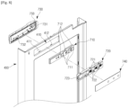
- FIG. 6 is an exploded perspective view illustrating a configuration of the inner door of the refrigerator of FIG. 1
- FIG. 7 is an exploded perspective view from a different angle illustrating the configuration of the inner door of the refrigerator of FIG. 1
- FIG. 8 is an exploded perspective view of a control unit disposed at the inner door of the refrigerator of FIG. 1
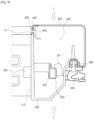
- FIG. 9 is a partial cross-sectional view of the inner door of the refrigerator of FIG. 1 .
- each of the door guards 40 may have an approximately box shape. Accordingly, each of the door guards 40 may include a front wall 41, a rear wall 42, a left wall 43, a right wall 44, a bottom 45, and a storage space 46 which stores food. A supporting groove 47 may be formed at each of the left wall 43 and the right wall 44 of the door guard 40.
- the inner door 200 may include an inner wall 310 provided at each sides of the opening 210 to support the door guard 40.
- a supporting protrusion 330 to be inserted into the supporting groove 47 of the door guard 40 may protrude from the inner wall 310.
- the supporting protrusion 330 is inserted into the supporting groove 47, thereby the door guard 40 is mounted in the opening 210.
- the door guard 40 described above may be detached from the opening 210.
- the door guard 40 may be provided to be slidable back and forth or up and down.
- the inner door 200 may include an inner panel 300, an outer panel 400 coupled with the inner panel 300 between which a foam space 500 (refer to FIG. 9 ) interposes, a plurality of installation members 600 coupled with a rear side of the inner panel 300 at which a gasket 650 (refer to FIG. 9 ) is installed, a plurality of reinforcing members 910 and 920 which prevent a twisting of the inner door 200, and a door trim 800 coupled between an end portion of the inner panel 300 and an end portion of the outer panel 400 to prevent a bubble solution foamed at the foam space 500 from leaking outward.
- the inner panel 300 may include an upper frame 301, a lower frame 302, a left frame 303, and a right frame 304 and may be formed of an integrally injection-molded resin material.
- the outer panel 400 may be formed of a metal material and may include an upper frame 401, a lower frame 402, a left frame 403, and a right frame 404.
- the inner panel 300 may include a pair of such inner walls 310 provided at both sides of the opening 210.
- the inner walls 310 may form the opening 210 and simultaneously may support the door guards 40.
- the door guards 40 may be disposed to be in contact with the outer door 100 of the opening 210 to allow the front wall 41 thereof to approximately form a part of a front side of the inner door 200.
- the door guards 40 may occupy the whole area of the opening 210, and a size thereof may be maximized. Also, since the door guards 40 are completely exposed when viewed from an outside of the inner door 200, a condition of food stored in the door guards 40 may be easily checked.
- the door guards 40 of the refrigerator 1 are provided at the opening 210 of the inner door 200.
- the outer door 100 may include an insulator provided between an inner panel 130 of the outer door 100 and an outer panel 120 of the outer door 100.
- the inner panel 130 of the outer door 100 may be formed by vacuum-molding a resin material, and the outer panel 120 of the outer door 100 may include a metal material.
- the plurality of installation members 600 are for installing the gasket 650 at the inner panel 300 while minimizing use of a complicated mold comprising a slide core, etc. during an injection molding of the inner panel 300 and are coupled with a rear side rim of the inner panel 300.
- the plurality of installation members 600 may include a first installation member 601 coupled with the upper frame 301 of the inner panel 300, a second installation member 602 coupled with the lower frame 302 of the inner panel 300, a third installation member 603 coupled with the left frame 303 of the inner panel 300, and a fourth installation member 604 coupled with the right frame 304 of the inner panel 300.
- first installation member 601, the second installation member 602, the third installation member 603, and the fourth installation member 604 may be provided to be spaced apart rather than connected. Accordingly, the first installation member 601, the second installation member 602, the third installation member 603, and the fourth installation member 604 may be prevented from mutually interrupting by expansion due to heat.
- the control unit 700 may include a circuit board 710 which transmits a control signal according to an input of the user and displays internal environment information of the storage compartments 20 and 30.
- a circuit board 710 which transmits a control signal according to an input of the user and displays internal environment information of the storage compartments 20 and 30.
- an operational portion 711 of the circuit board 710 may recognize the input of the user, and the display portion 712 may display the internal environment information of the storage compartments 20 and 30.
- the circuit board 710 may further include a locking setting function for preventing a misoperation of the operational portion 711, a power-saving setting function for saving power of a refrigerator, etc.
- a wireless communication function capable of wirelessly operating settings of the refrigerator using a mobile device may be further included.
- the circuit board 710 may be contained in a housing 730 and may be fixed by a cover 720.
- the cover 720 may include a coupling hook 723 for coupling with the housing 730, and the housing 730 may include a hook holding portion 731 for coupling with the coupling hook of the cover 720.
- the cover 720 which covers the circuit board 710 of the control unit 700 may include a button portion 721 which operates on the operational portion 711 of the circuit board 710 and an opening 722 provided to expose the display portion 712.
- the user may input desired settings into the operational portion 7111 of the circuit board 710 by pressurizing the button portion 721. Since the display portion 712 of the circuit board 710 is exposed through the opening 722 of the cover 720, the user may check environment information displayed on the display portion 712 even when the circuit board 710 is covered with the cover 720.
- the control unit 700 may be disposed in a space between the outer panel 400 and the inner panel 300 of the inner door 200 and may be mounted on the outer panel 400.
- the outer panel 400 of the inner door 200 may include the upper frame 401, the lower frame 402, the left frame 403, and the right frame 404, and at least one of among them may be provided with a mounting portion 410 for mounting the control unit 700.
- the housing 730 of the control unit 700 may include a coupling hook 732 to be coupled with the mounting portion 410.
- the housing 730 may include a cable connecting portion 733 for connecting a cable to the circuit board 710 accommodated therein.
- the mounting portion 410 may include a hook holding portion 412 capable of being coupled with the coupling hook 732 of the housing 730 and may include an opening 411 to expose the cover 720 of the control unit 700.
- the control unit 700 may further include a transmission member (which may also be referred to as a transparent member) 740 for finishing of the cover 720. Since the transmission member 740 is an outermost component of the control unit 700, the transmission member 740 may not only have a function of preventing foreign substances from penetrating the control unit 700 but also an aesthetic function. Accordingly, not only a function of the button portion 721 corresponding to the button portion 721 of the cover 720 but also other elements of design may be printed on the transmission member 740.
- a transmission member which may also be referred to as a transparent member
- the transmission member 740 may be formed of a material through which light shown on the display portion 712 of the circuit board 710 may pass and may be formed of a flexible resin material to pressurize the button portion 721.
- the transmission member 740 may include an adhesive layer formed on a rear side thereof to be adhered to the cover 720.
- the door trim 800 is for preventing the bubble solution in the foam space 500 between the inner panel 300 and the outer panel 400 from leaking outward.
- the door trim 800 may include an insertion groove in which an end portion 311 of the inner wall 310 of the inner panel 300 is press fittingly inserted and an insertion groove in which an end portion 405 of the outer panel 400 is press fittingly inserted.
- a coupling groove in which a coupling protrusion 406 of the outer panel 400 is inserted may be formed to reinforce a coupling force between the door trim 800 and the outer panel 400.
- a foaming process of the inner door 200 including the door trim 800 is as follows.
- control unit 700 is disposed at the mounting portion 410 of the outer panel 400.
- the housing 730 of the control unit 700 and the outer panel 400 are sealed not to allow the bubble solution to penetrate.
- the cable connecting portion 733 provided to connect the cable to the circuit board 710 accommodated in the housing 730 may also be sealed.
- the inner panel 300, the outer panel 400, and the door trim 800 are preliminarily coupled, the inner panel 300 is disposed to face a bottom surface, and the outer panel 400 is disposed to face upward, and then the inner panel 300 and the outer panel 400 are pressurized in a vertical direction F using a fixing jig (not shown).
- the bubble solution is inserted into the foam space 500 formed between the inner panel 300 and the outer panel 400 for foaming.
- the inner panel 300 and the outer panel 400 are pressurized in the vertical direction F, the inner panel 300 and the outer panel 400 are not forced apart due to a foaming pressure in the vertical direction F. Accordingly, the bubble solution may not leak in the vertical direction.
- the door trim 800 tightly holds the end portion of the inner panel 300 and the end portion of the outer panel 400, the inner panel 300 and the outer panel 400 are not forced apart by a foaming pressure in a horizontal direction, and the bubble solution may not leak.
- the bubble solution may leak through a gap formed due to a foaming pressure.
- the inner panel 300, the outer panel 400, and the door trim 800 may be strongly coupled and the control unit 700 may also be strongly coupled with the outer panel 400 by an adhesive force of the bubble solution.
- the inner door 200 of the refrigerator 1 in accordance with one embodiment of the present disclosure is vulnerable to a twisting due to the opening 210. Also, a twisting may occur or the inner wall 310 may be not formed even due to a foaming pressure in a foaming process of the inner door 200.
- the plurality of reinforcing members 910 and 920 may be provided at the inner door 200 to overcome the above described vulnerability.
- the plurality of reinforcing members 910 and 920 may include a first reinforcing member 910 which crosses the opening 210 and connects the left frame 303 of the inner panel 300 with the right frame 304 of the inner panel 300 and a second reinforcing member 920 provided at the upper frame 301 of the inner panel 300, the lower frame 302 of the inner panel 300, the left frame 303 of the inner panel 300, and the right frame 304 of the inner panel 300.
- the second reinforcing member 920 may include an upper reinforcing portion 921, a lower reinforcing portion 922, a left reinforcing portion 923, and a right reinforcing portion 924 and may be provided in an approximate quadrangular frame shape.
- the second reinforcing member 920 may be integrally formed of a metal material having hardness.
- an accommodating space 350 which accommodates the second reinforcing member 920 and the hook portion 351 which fixes the second reinforcing member 920 may be formed at the inner panel 300. Accordingly, the second reinforcing member 920 may be coupled with the inner panel 300 and may be disposed between the inner panel 300 and the outer panel 400. Accordingly, the second reinforcing member 920 may be not exposed to the outside.
- the second reinforcing member 920 may be fixed to the inner panel 300 before the bubble solution is foamed in the foam space formed between the inner panel 300 and the outer panel 400.
- the first reinforcing member 910 prevents the twisting of the inner door 200 by directly connecting the relatively long left frame 303 of the inner panel 300 and the right frame 304 of the inner panel 300 across the opening 210.
- the second reinforcing member 920 is provided at each of the upper frame 301 of the inner panel 300, the lower frame 302 of the inner panel 300, the left frame 303 of the inner panel 300, and the right frame 304 of the inner panel 300 to reinforce four sides, thereby preventing the twisting of the inner door 200.
- first reinforcing member 910 and the second reinforcing member 920 are provided in the embodiment of the present disclosure, only one of the first reinforcing member 910 and the second reinforcing member 920 may be provided as necessary.
- FIG. 10 is a view of a refrigerator in accordance with an example which is not part of the invention, in which a transparent window is provided at the outer door.
- a transparent window 750 may be provided at the outer door 100 of the refrigerator 1 for checking the display portion 712 of the control unit 700 with the outer door 100 closed. With the outer door 100 closed, the transparent window 750 is provided at a position corresponding to a position of the control unit 700 disposed at the inner door 200. The transparent window 750 is provided to be through both the outer panel 120 and the inner panel 130 of the outer door 100.
- the transparent window 759 may be formed of a conductive material for operating the control unit 700 even with the outer door 100 closed.
- FIG. 11 is a view of a refrigerator in accordance with an embodiment of the present disclosure in which an outer door is totally formed with a transparent window.
- the outer door (100) comprises a transparent or translucent material (140).
- the outer door 100 may be formed of a transparent or translucent material to check not only the control unit 700 but also an inside of the refrigerating compartment 30 with the outer door 100 closed.
- the entire outer door 100 may be formed of the transparent or translucent material, or a part of the outer door 100 may be formed of the transparent or translucent material.
- both the outer panel 120 and the inner panel 130 of the outer door 100 may be formed of a transparent or translucent panel 140 including a glass material, etc. and an insulating layer including an air layer, etc. may be included between panels. Also, there may be formed a single transparent panel 140.
- the transparent panel 140 may be formed of a conductive material for operating the control unit 700 even with the outer door 100 closed.
Landscapes
- Engineering & Computer Science (AREA)
- Physics & Mathematics (AREA)
- Thermal Sciences (AREA)
- Chemical & Material Sciences (AREA)
- Combustion & Propulsion (AREA)
- Mechanical Engineering (AREA)
- General Engineering & Computer Science (AREA)
- Refrigerator Housings (AREA)
- Cold Air Circulating Systems And Constructional Details In Refrigerators (AREA)
Claims (12)
- Kühlschrank, der Folgendes umfasst:einen Körper (10);ein Lagerfach (30), das im Körper (10) ausgebildet ist;eine Innentür (200), die einen Rahmen (220) umfasst, der eine Öffnung (210) ausbildet und schwenkbar mit dem Körper (10) gekoppelt ist, wobei die Öffnung (210) der Innentür (200) Zugriff auf das Lagerfach (30) bereitstellt und wobei die Öffnung (210) eine Vielzahl von Türeinsätzen (40) beinhaltet, die in der Lage sind, Lebensmittel aufzubewahren;eine Außentür (100), die in Bezug auf die Innentür (200) schwenkbar ist und die Öffnung (210) der Innentür (200) öffnet und verschließt;einen Montageabschnitt (410), der am Rahmen (220) der Innentür (200) bereitgestellt ist; undeine Steuereinheit (700), die konfiguriert ist, um eine Innenumgebung des Lagerfachs (30) zu steuern, und die an dem Montageabschnitt (410) montiert ist;wobei die Steuereinheit (700) durch die Außentür (100) abgedeckt ist, wenn die Außentür (100) geschlossen ist,wobei die Außentür (100) ein transparentes oder lichtdurchlässiges Material (140) umfasst, undwobei die Innentür (200) und die Außentür (100) so konfiguriert sind, dassbei geschlossener Außentür (100) die Steuereinheit (700) und die in den Türeinsätzen (40) aufbewahrten Lebensmittel für einen Benutzer durch das transparente oder lichtdurchlässige Material (140) sichtbar sind, undbei geschlossener Innentür (200) und geöffneter Außentür (100) die Steuereinheit (800) und die in den Türeinsätzen (40) aufbewahrten Lebensmittel für einen Benutzer von außerhalb des Kühlschranks zugänglich sind.
- Kühlschrank nach Anspruch 1, wobei die Steuereinheit (700) eine Leiterplatte (710) umfasst, die ein Steuersignal gemäß einer Eingabe des Benutzers überträgt und Innenumgebungsinformationen des Lagerfachs (30) anzeigt.
- Kühlschrank nach einem der vorhergehenden Ansprüche, wobei die Steuereinheit (700) einen Betriebsabschnitt (711) und einen Anzeigeabschnitt (712) umfasst.
- Kühlschrank nach einem der vorhergehenden Ansprüche, wobei die Steuereinheit (700) so konfiguriert ist, dass sie mindestens eines von einer Temperatur, einer Luftfeuchtigkeit, einem Geruch und einer Beleuchtung des Lagerfachs (30) steuert.
- Kühlschrank nach einem der vorhergehenden Ansprüche, wobei die Steuereinheit (700) Folgendes umfasst:eine Leiterplatte (710), die einen Betriebsabschnitt (711) und den Anzeigeabschnitt (712) umfasst; undeine Abdeckung (720), die die Leiterplatte (710) abdeckt, wobei die Abdeckung (720) einen Tastenabschnitt (721) zum Bedienen des Betriebsabschnitts (711) und eine Öffnung (722) umfasst, die den Anzeigeabschnitt (712) freilegt.
- Kühlschrank nach Anspruch 5, wobeidie Steuereinheit (700) ein Gehäuse (730) umfasst, das die Leiterplatte (710) und die Abdeckung (720) aufnimmt, unddas Gehäuse (730) mit dem Montageabschnitt (410) der Innentür (200) gekoppelt ist.
- Kühlschrank nach einem der Ansprüche 5 und 6, wobei die Steuereinheit (700) ein transparentes Element (740) umfasst, das die Abdeckung (720) abdeckt und auf dem eine Funktion des Tastenabschnitts (721) angezeigt ist.
- Kühlschrank nach einem der vorhergehenden Ansprüche, wobeider Rahmen (220) einen oberen Rahmen (401), einen unteren Rahmen (402), einen linken Rahmen (403) und einen rechten Rahmen (404) umfasst, die die Öffnung (210) bilden, unddie Steuereinheit (700) an mindestens einem von dem oberen Rahmen (401), dem unteren Rahmen (402), dem linken Rahmen (403) und dem rechten Rahmen (404) angeordnet ist.
- Kühlschrank nach einem der vorhergehenden Ansprüche, wobeidie Innentür (200) eine Innenplatte (300), eine Außenplatte (400), die einen Zwischenraum (500) mit der Innenplatte (300) bildet, und einen in dem Zwischenraum (500) aufgeschäumten Isolator umfasst, unddie Steuereinheit (700) zwischen der Innenplatte (300) und der Außenplatte (400) angeordnet ist.
- Kühlschrank nach Anspruch 9,
wobei die Innenplatte (300) eine Innenwand (310) umfasst, die die Öffnung (210) bildet und die Vielzahl von Türeinsätzen (40) trägt. - Kühlschrank nach Anspruch 10, wobei jeder der Vielzahl von Türeinsätzen (40) eine vordere Wand (41), eine hintere Wand (42), zwei Seitenwände (43, 44), einen Boden (45) und einen Lagerraum (46) umfasst.
- Kühlschrank nach Anspruch 11, wobei die vordere Wand (41) von jedem der Vielzahl von Türeinsätzen (40) einen Teil einer Vorderseite der Innentür (200) bildet.
Priority Applications (1)
| Application Number | Priority Date | Filing Date | Title |
|---|---|---|---|
| EP24208406.9A EP4491987A3 (de) | 2015-07-08 | 2016-06-29 | Kühlschrank |
Applications Claiming Priority (3)
| Application Number | Priority Date | Filing Date | Title |
|---|---|---|---|
| KR1020150097318A KR102098689B1 (ko) | 2015-07-08 | 2015-07-08 | 냉장고 |
| PCT/KR2016/006949 WO2017007164A1 (en) | 2015-07-08 | 2016-06-29 | Refrigerator |
| EP16821570.5A EP3283832B1 (de) | 2015-07-08 | 2016-06-29 | Kühlschrank |
Related Parent Applications (2)
| Application Number | Title | Priority Date | Filing Date |
|---|---|---|---|
| EP16821570.5A Division-Into EP3283832B1 (de) | 2015-07-08 | 2016-06-29 | Kühlschrank |
| EP16821570.5A Division EP3283832B1 (de) | 2015-07-08 | 2016-06-29 | Kühlschrank |
Related Child Applications (2)
| Application Number | Title | Priority Date | Filing Date |
|---|---|---|---|
| EP24208406.9A Division EP4491987A3 (de) | 2015-07-08 | 2016-06-29 | Kühlschrank |
| EP24208406.9A Division-Into EP4491987A3 (de) | 2015-07-08 | 2016-06-29 | Kühlschrank |
Publications (3)
| Publication Number | Publication Date |
|---|---|
| EP4148359A1 EP4148359A1 (de) | 2023-03-15 |
| EP4148359B1 true EP4148359B1 (de) | 2025-01-15 |
| EP4148359C0 EP4148359C0 (de) | 2025-01-15 |
Family
ID=57685808
Family Applications (3)
| Application Number | Title | Priority Date | Filing Date |
|---|---|---|---|
| EP22205526.1A Active EP4148359B1 (de) | 2015-07-08 | 2016-06-29 | Kühlschrank |
| EP24208406.9A Pending EP4491987A3 (de) | 2015-07-08 | 2016-06-29 | Kühlschrank |
| EP16821570.5A Active EP3283832B1 (de) | 2015-07-08 | 2016-06-29 | Kühlschrank |
Family Applications After (2)
| Application Number | Title | Priority Date | Filing Date |
|---|---|---|---|
| EP24208406.9A Pending EP4491987A3 (de) | 2015-07-08 | 2016-06-29 | Kühlschrank |
| EP16821570.5A Active EP3283832B1 (de) | 2015-07-08 | 2016-06-29 | Kühlschrank |
Country Status (8)
| Country | Link |
|---|---|
| US (6) | US10174994B2 (de) |
| EP (3) | EP4148359B1 (de) |
| KR (1) | KR102098689B1 (de) |
| CN (2) | CN115507615A (de) |
| AU (1) | AU2016291014B2 (de) |
| DE (2) | DE202016008965U1 (de) |
| PL (1) | PL3283832T3 (de) |
| WO (1) | WO2017007164A1 (de) |
Families Citing this family (20)
| Publication number | Priority date | Publication date | Assignee | Title |
|---|---|---|---|---|
| KR102009947B1 (ko) * | 2013-01-02 | 2019-08-12 | 엘지전자 주식회사 | 가전기기 |
| KR102245370B1 (ko) | 2013-06-14 | 2021-04-28 | 엘지전자 주식회사 | 냉장고 |
| KR102098689B1 (ko) | 2015-07-08 | 2020-04-08 | 삼성전자주식회사 | 냉장고 |
| CN106605116B (zh) * | 2015-07-15 | 2020-02-07 | Lg电子株式会社 | 用于家电的门、家电及其制造方法 |
| DE202015107063U1 (de) * | 2015-12-23 | 2017-03-27 | Rehau Ag + Co. | Profilanordnung, insbesondere für ein Kühl- und / oder Gefriergerät |
| KR102470041B1 (ko) * | 2017-08-29 | 2022-11-23 | 삼성전자주식회사 | 냉장고 |
| US11650628B1 (en) * | 2018-10-03 | 2023-05-16 | Anthony, Inc. | Display case door with touch screen |
| CN109780800B (zh) * | 2019-01-04 | 2023-03-31 | 海尔智家股份有限公司 | 具有显示屏组件的门中门及具有其的冰箱 |
| DE102019203114A1 (de) * | 2019-03-07 | 2020-09-10 | BSH Hausgeräte GmbH | Haushaltskältegerät mit einer Anzeige- und/oder Bedieneinheit |
| KR102312667B1 (ko) | 2019-04-15 | 2021-10-15 | 삼성전자주식회사 | 냉장고 |
| WO2020213861A1 (en) | 2019-04-15 | 2020-10-22 | Samsung Electronics Co., Ltd. | Refrigerator |
| EP3799616B1 (de) * | 2019-08-20 | 2023-05-03 | Samsung Electronics Co., Ltd. | Kühlschrank |
| KR102869954B1 (ko) | 2019-11-13 | 2025-10-14 | 엘지전자 주식회사 | 도어조립체 및 이를 포함하는 냉장고 |
| CN112797711A (zh) | 2019-11-13 | 2021-05-14 | Lg电子株式会社 | 冰箱 |
| KR102868813B1 (ko) | 2019-11-13 | 2025-10-02 | 엘지전자 주식회사 | 도어조립체 및 이를 포함하는 냉장고 |
| KR20210125379A (ko) | 2020-04-08 | 2021-10-18 | 삼성전자주식회사 | 냉장고 |
| KR20220101524A (ko) | 2021-01-11 | 2022-07-19 | 엘지전자 주식회사 | 냉장고 |
| US12061041B2 (en) * | 2021-12-09 | 2024-08-13 | Anthony, Inc. | Display case door with sealed glass unit and electronic display |
| JP7642580B2 (ja) * | 2022-02-15 | 2025-03-10 | 日立グローバルライフソリューションズ株式会社 | 断熱扉及びこれを備える貯蔵庫 |
| KR20250139595A (ko) * | 2024-03-15 | 2025-09-23 | 엘지전자 주식회사 | 냉장고 |
Family Cites Families (51)
| Publication number | Priority date | Publication date | Assignee | Title |
|---|---|---|---|---|
| US3367730A (en) * | 1966-07-25 | 1968-02-06 | Vendo Co | Refrigerated dispensing cabinet having outer decorative door and inner locked product access door |
| US4834231A (en) * | 1984-09-20 | 1989-05-30 | Sanyo Electric Co., Ltd. | Vending machine with management mode selection indicators |
| US4706794A (en) * | 1984-09-20 | 1987-11-17 | Sanyo Electric Co., Ltd. | Vending machine with a common display |
| US4966004A (en) * | 1989-11-06 | 1990-10-30 | Amana Refrigeration, Inc. | Electronic control mounting apparatus for refrigerator |
| US5291003A (en) * | 1991-10-11 | 1994-03-01 | Verifone, Inc. | Modular cash card system design |
| NZ248935A (en) * | 1992-11-02 | 1995-10-26 | White Consolidated Ind Inc | Refrigerator door ice dispenser: actuator dimensioned to accommodate polystyrene cup |
| US6067738A (en) * | 1995-09-13 | 2000-05-30 | Zeligson; Stephen J. | Refrigerator door display lens |
| US6483695B1 (en) * | 1996-06-24 | 2002-11-19 | Stanley Hartstein | Computer/keyboard built into refrigerator door |
| US6484529B2 (en) * | 2000-04-19 | 2002-11-26 | Whirlpool Corporation | Cabinet construction for an ice maker or other refrigeration appliance |
| CN1141545C (zh) * | 2001-04-30 | 2004-03-10 | 广东科龙电器股份有限公司 | 无线连接的双向开门冰箱 |
| KR20060081938A (ko) * | 2005-01-11 | 2006-07-14 | 삼성전자주식회사 | 냉장고 |
| WO2006098591A1 (en) * | 2005-03-16 | 2006-09-21 | Lg Electronics Inc. | Damper embedded in a home bar door of a refrigerator and method for manufacturing the same |
| WO2007011178A1 (en) * | 2005-07-20 | 2007-01-25 | Lg Electronics Inc. | Refrigerator door and method of manufacture thereof |
| WO2007078149A1 (en) * | 2006-01-03 | 2007-07-12 | Lg Electronics Inc. | A display for refrigerator and display mounting frame, display mounting structure comprising the sames |
| US7568358B2 (en) * | 2006-01-09 | 2009-08-04 | Maytag Corporation | Control for a refrigerator door dispenser light |
| US7878009B2 (en) * | 2006-08-30 | 2011-02-01 | U-Line Corporation | Cooling unit with data logging control |
| KR101351090B1 (ko) * | 2007-01-16 | 2014-01-14 | 삼성전자주식회사 | 냉장고 |
| KR100894479B1 (ko) * | 2007-11-30 | 2009-04-22 | 엘지전자 주식회사 | 절환실을 구비한 냉장고 |
| KR101346502B1 (ko) * | 2008-02-21 | 2013-12-31 | 엘지전자 주식회사 | 냉장고 및 냉장고 도어의 제조방법 |
| EP2131123A3 (de) * | 2008-03-12 | 2010-05-26 | Whirlpool Corporation | Externer Pendelbecher |
| KR101602431B1 (ko) * | 2008-11-05 | 2016-03-10 | 삼성전자 주식회사 | 냉장고 |
| CN201455962U (zh) * | 2009-07-30 | 2010-05-12 | 杜雨洋 | 新型钢制电力安全工器具柜 |
| CN102116554A (zh) * | 2010-01-04 | 2011-07-06 | Lg电子株式会社 | 电冰箱 |
| RU2502926C2 (ru) * | 2010-02-01 | 2013-12-27 | ЭлДжи ЭЛЕКТРОНИКС ИНК. | Холодильник |
| KR101297029B1 (ko) | 2010-02-01 | 2013-08-14 | 엘지전자 주식회사 | 냉장고 및 냉장고의 제어방법 |
| KR101346488B1 (ko) * | 2010-02-01 | 2014-01-02 | 엘지전자 주식회사 | 냉장고 |
| BR112012006216B1 (pt) * | 2010-02-01 | 2020-06-16 | Lg Electronics Inc. | Refrigerador e método para controlar o mesmo |
| KR20110139844A (ko) * | 2010-06-24 | 2011-12-30 | 삼성전자주식회사 | 센서장치를 갖는 냉장고용 수납용기 및 이를 갖는 냉장고 |
| DE102010037397A1 (de) * | 2010-09-08 | 2012-03-08 | Miele & Cie. Kg | Haushaltgerät, insbesondere grifflose Geschirrspülmaschine |
| KR101768699B1 (ko) | 2010-12-07 | 2017-08-17 | 엘지전자 주식회사 | 냉장고용 이중 도어 개폐 장치 |
| KR101844072B1 (ko) * | 2011-11-11 | 2018-05-15 | 엘지전자 주식회사 | 냉장고 |
| CN202582007U (zh) * | 2012-03-29 | 2012-12-05 | 海信容声(广东)冷柜有限公司 | 一种面板门 |
| KR101918296B1 (ko) * | 2012-06-21 | 2019-01-29 | 엘지전자 주식회사 | 냉장고 |
| KR102025734B1 (ko) * | 2012-11-09 | 2019-09-27 | 삼성전자주식회사 | 냉장고 및 그 내부 도어의 제조 방법 |
| KR102028014B1 (ko) * | 2012-11-09 | 2019-10-02 | 삼성전자주식회사 | 냉장고 및 그 내부 도어의 제조 방법 |
| KR20140102511A (ko) * | 2013-02-14 | 2014-08-22 | 엘지전자 주식회사 | 냉장고 |
| KR101860718B1 (ko) * | 2013-02-21 | 2018-05-24 | 삼성전자주식회사 | 이중 도어를 갖는 냉장고 |
| US8960934B2 (en) * | 2013-04-08 | 2015-02-24 | Samsung Electronics Co., Ltd. | Refrigerator and method of manufacturing the same |
| KR20140131759A (ko) | 2013-05-06 | 2014-11-14 | 엘지전자 주식회사 | 냉장고 |
| KR102156123B1 (ko) * | 2013-08-12 | 2020-09-15 | 엘지전자 주식회사 | 냉장고 |
| KR102220809B1 (ko) | 2013-08-22 | 2021-02-26 | 삼성전자주식회사 | 냉장고 |
| ES2671484T3 (es) * | 2013-12-23 | 2018-06-06 | Lg Electronics Inc. | Nevera |
| CN203654382U (zh) * | 2013-12-26 | 2014-06-18 | 天津市图程新技术有限公司 | 一种双开门供水柜 |
| US9972284B2 (en) * | 2014-02-12 | 2018-05-15 | Lg Electronics Inc. | Refrigerator with interactive display and control method thereof |
| US10473389B2 (en) * | 2014-02-28 | 2019-11-12 | Electrolux Home Products, Inc. | Dual use user interface and door position sensors |
| KR102228916B1 (ko) * | 2014-03-11 | 2021-03-17 | 삼성전자주식회사 | 냉장고 |
| CN104499897B (zh) * | 2014-11-26 | 2017-06-27 | 珠海格力电器股份有限公司 | 一种玻璃门安装结构及电器 |
| KR20160115445A (ko) * | 2015-03-27 | 2016-10-06 | 삼성전자주식회사 | 냉장고 |
| WO2016175563A1 (en) * | 2015-04-27 | 2016-11-03 | Lg Electronics Inc. | Refrigerator with door and refrigerator door manufacturing method |
| KR102098689B1 (ko) | 2015-07-08 | 2020-04-08 | 삼성전자주식회사 | 냉장고 |
| KR101810760B1 (ko) * | 2016-01-05 | 2017-12-19 | 엘지전자 주식회사 | 냉장고 및 냉장고의 제어 방법 |
-
2015
- 2015-07-08 KR KR1020150097318A patent/KR102098689B1/ko active Active
-
2016
- 2016-06-29 AU AU2016291014A patent/AU2016291014B2/en active Active
- 2016-06-29 WO PCT/KR2016/006949 patent/WO2017007164A1/en not_active Ceased
- 2016-06-29 DE DE202016008965.0U patent/DE202016008965U1/de active Active
- 2016-06-29 CN CN202211308309.8A patent/CN115507615A/zh active Pending
- 2016-06-29 EP EP22205526.1A patent/EP4148359B1/de active Active
- 2016-06-29 CN CN201680036949.4A patent/CN107709906A/zh active Pending
- 2016-06-29 PL PL16821570.5T patent/PL3283832T3/pl unknown
- 2016-06-29 EP EP24208406.9A patent/EP4491987A3/de active Pending
- 2016-06-29 DE DE202016008931.6U patent/DE202016008931U1/de active Active
- 2016-06-29 EP EP16821570.5A patent/EP3283832B1/de active Active
- 2016-07-07 US US15/204,530 patent/US10174994B2/en active Active
-
2018
- 2018-11-28 US US16/202,711 patent/US10451342B2/en active Active
-
2019
- 2019-09-12 US US16/569,259 patent/US11022368B2/en active Active
-
2021
- 2021-04-23 US US17/238,988 patent/US11460243B2/en active Active
-
2022
- 2022-08-31 US US17/900,286 patent/US11885559B2/en active Active
-
2023
- 2023-12-06 US US18/531,160 patent/US12235039B2/en active Active
Also Published As
| Publication number | Publication date |
|---|---|
| EP4491987A2 (de) | 2025-01-15 |
| KR20170006542A (ko) | 2017-01-18 |
| US20190113277A1 (en) | 2019-04-18 |
| EP3283832B1 (de) | 2022-12-14 |
| AU2016291014B2 (en) | 2021-09-09 |
| EP4148359A1 (de) | 2023-03-15 |
| KR102098689B1 (ko) | 2020-04-08 |
| US20210239393A1 (en) | 2021-08-05 |
| EP3283832A4 (de) | 2018-07-25 |
| US20200003485A1 (en) | 2020-01-02 |
| AU2016291014A1 (en) | 2017-09-21 |
| US11022368B2 (en) | 2021-06-01 |
| US11885559B2 (en) | 2024-01-30 |
| US20220412647A1 (en) | 2022-12-29 |
| CN107709906A (zh) | 2018-02-16 |
| US12235039B2 (en) | 2025-02-25 |
| US10174994B2 (en) | 2019-01-08 |
| CN115507615A (zh) | 2022-12-23 |
| US11460243B2 (en) | 2022-10-04 |
| PL3283832T3 (pl) | 2023-05-02 |
| WO2017007164A1 (en) | 2017-01-12 |
| US20170010040A1 (en) | 2017-01-12 |
| US10451342B2 (en) | 2019-10-22 |
| EP4491987A3 (de) | 2025-03-26 |
| US20240102727A1 (en) | 2024-03-28 |
| EP3283832A1 (de) | 2018-02-21 |
| EP4148359C0 (de) | 2025-01-15 |
| DE202016008965U1 (de) | 2021-02-03 |
| DE202016008931U1 (de) | 2020-10-21 |
Similar Documents
| Publication | Publication Date | Title |
|---|---|---|
| US12235039B2 (en) | Refrigerator | |
| KR101602431B1 (ko) | 냉장고 | |
| EP2865972B1 (de) | Kühlschrank aufweisend eine kühlschranktür | |
| EP2730869B1 (de) | Kühlschrank | |
| US9791197B2 (en) | Refrigerator with rear panel for accommodating water hose | |
| EP3343148A1 (de) | Kühlschrank | |
| EP3674632B1 (de) | Kühlschrank | |
| KR102302389B1 (ko) | 냉장고 | |
| US8109106B2 (en) | Malfunction preventing device for refrigerator and method thereof | |
| KR102717565B1 (ko) | 냉장고 | |
| KR102428160B1 (ko) | 냉장고 | |
| CN220750508U (zh) | 门体及冰箱 | |
| US20240210097A1 (en) | Refrigerator | |
| KR20240133333A (ko) | 냉장고 | |
| JP2019135444A (ja) | 冷蔵庫 |
Legal Events
| Date | Code | Title | Description |
|---|---|---|---|
| PUAI | Public reference made under article 153(3) epc to a published international application that has entered the european phase |
Free format text: ORIGINAL CODE: 0009012 |
|
| STAA | Information on the status of an ep patent application or granted ep patent |
Free format text: STATUS: THE APPLICATION HAS BEEN PUBLISHED |
|
| AC | Divisional application: reference to earlier application |
Ref document number: 3283832 Country of ref document: EP Kind code of ref document: P |
|
| AK | Designated contracting states |
Kind code of ref document: A1 Designated state(s): AL AT BE BG CH CY CZ DE DK EE ES FI FR GB GR HR HU IE IS IT LI LT LU LV MC MK MT NL NO PL PT RO RS SE SI SK SM TR |
|
| STAA | Information on the status of an ep patent application or granted ep patent |
Free format text: STATUS: REQUEST FOR EXAMINATION WAS MADE |
|
| 17P | Request for examination filed |
Effective date: 20230516 |
|
| RBV | Designated contracting states (corrected) |
Designated state(s): AL AT BE BG CH CY CZ DE DK EE ES FI FR GB GR HR HU IE IS IT LI LT LU LV MC MK MT NL NO PL PT RO RS SE SI SK SM TR |
|
| GRAP | Despatch of communication of intention to grant a patent |
Free format text: ORIGINAL CODE: EPIDOSNIGR1 |
|
| STAA | Information on the status of an ep patent application or granted ep patent |
Free format text: STATUS: GRANT OF PATENT IS INTENDED |
|
| RIC1 | Information provided on ipc code assigned before grant |
Ipc: F25D 29/00 20060101ALI20240717BHEP Ipc: F25D 23/02 20060101AFI20240717BHEP |
|
| INTG | Intention to grant announced |
Effective date: 20240813 |
|
| GRAS | Grant fee paid |
Free format text: ORIGINAL CODE: EPIDOSNIGR3 |
|
| GRAA | (expected) grant |
Free format text: ORIGINAL CODE: 0009210 |
|
| STAA | Information on the status of an ep patent application or granted ep patent |
Free format text: STATUS: THE PATENT HAS BEEN GRANTED |
|
| AC | Divisional application: reference to earlier application |
Ref document number: 3283832 Country of ref document: EP Kind code of ref document: P |
|
| AK | Designated contracting states |
Kind code of ref document: B1 Designated state(s): AL AT BE BG CH CY CZ DE DK EE ES FI FR GB GR HR HU IE IS IT LI LT LU LV MC MK MT NL NO PL PT RO RS SE SI SK SM TR |
|
| REG | Reference to a national code |
Ref country code: CH Ref legal event code: EP Ref country code: GB Ref legal event code: FG4D |
|
| REG | Reference to a national code |
Ref country code: DE Ref legal event code: R096 Ref document number: 602016090985 Country of ref document: DE |
|
| REG | Reference to a national code |
Ref country code: IE Ref legal event code: FG4D |
|
| U01 | Request for unitary effect filed |
Effective date: 20250206 |
|
| U07 | Unitary effect registered |
Designated state(s): AT BE BG DE DK EE FI FR IT LT LU LV MT NL PT RO SE SI Effective date: 20250213 |
|
| PG25 | Lapsed in a contracting state [announced via postgrant information from national office to epo] |
Ref country code: RS Free format text: LAPSE BECAUSE OF FAILURE TO SUBMIT A TRANSLATION OF THE DESCRIPTION OR TO PAY THE FEE WITHIN THE PRESCRIBED TIME-LIMIT Effective date: 20250415 |
|
| PG25 | Lapsed in a contracting state [announced via postgrant information from national office to epo] |
Ref country code: PL Free format text: LAPSE BECAUSE OF FAILURE TO SUBMIT A TRANSLATION OF THE DESCRIPTION OR TO PAY THE FEE WITHIN THE PRESCRIBED TIME-LIMIT Effective date: 20250115 |
|
| PG25 | Lapsed in a contracting state [announced via postgrant information from national office to epo] |
Ref country code: ES Free format text: LAPSE BECAUSE OF FAILURE TO SUBMIT A TRANSLATION OF THE DESCRIPTION OR TO PAY THE FEE WITHIN THE PRESCRIBED TIME-LIMIT Effective date: 20250115 |
|
| PGFP | Annual fee paid to national office [announced via postgrant information from national office to epo] |
Ref country code: GB Payment date: 20250520 Year of fee payment: 10 |
|
| PG25 | Lapsed in a contracting state [announced via postgrant information from national office to epo] |
Ref country code: NO Free format text: LAPSE BECAUSE OF FAILURE TO SUBMIT A TRANSLATION OF THE DESCRIPTION OR TO PAY THE FEE WITHIN THE PRESCRIBED TIME-LIMIT Effective date: 20250415 Ref country code: IS Free format text: LAPSE BECAUSE OF FAILURE TO SUBMIT A TRANSLATION OF THE DESCRIPTION OR TO PAY THE FEE WITHIN THE PRESCRIBED TIME-LIMIT Effective date: 20250515 |
|
| PG25 | Lapsed in a contracting state [announced via postgrant information from national office to epo] |
Ref country code: HR Free format text: LAPSE BECAUSE OF FAILURE TO SUBMIT A TRANSLATION OF THE DESCRIPTION OR TO PAY THE FEE WITHIN THE PRESCRIBED TIME-LIMIT Effective date: 20250115 |
|
| PG25 | Lapsed in a contracting state [announced via postgrant information from national office to epo] |
Ref country code: GR Free format text: LAPSE BECAUSE OF FAILURE TO SUBMIT A TRANSLATION OF THE DESCRIPTION OR TO PAY THE FEE WITHIN THE PRESCRIBED TIME-LIMIT Effective date: 20250416 |
|
| PGFP | Annual fee paid to national office [announced via postgrant information from national office to epo] |
Ref country code: TR Payment date: 20250509 Year of fee payment: 10 |
|
| U20 | Renewal fee for the european patent with unitary effect paid |
Year of fee payment: 10 Effective date: 20250624 |
|
| PG25 | Lapsed in a contracting state [announced via postgrant information from national office to epo] |
Ref country code: SM Free format text: LAPSE BECAUSE OF FAILURE TO SUBMIT A TRANSLATION OF THE DESCRIPTION OR TO PAY THE FEE WITHIN THE PRESCRIBED TIME-LIMIT Effective date: 20250115 |
|
| PG25 | Lapsed in a contracting state [announced via postgrant information from national office to epo] |
Ref country code: CZ Free format text: LAPSE BECAUSE OF FAILURE TO SUBMIT A TRANSLATION OF THE DESCRIPTION OR TO PAY THE FEE WITHIN THE PRESCRIBED TIME-LIMIT Effective date: 20250115 |
|
| PG25 | Lapsed in a contracting state [announced via postgrant information from national office to epo] |
Ref country code: SK Free format text: LAPSE BECAUSE OF FAILURE TO SUBMIT A TRANSLATION OF THE DESCRIPTION OR TO PAY THE FEE WITHIN THE PRESCRIBED TIME-LIMIT Effective date: 20250115 |
|
| PLBE | No opposition filed within time limit |
Free format text: ORIGINAL CODE: 0009261 |
|
| STAA | Information on the status of an ep patent application or granted ep patent |
Free format text: STATUS: NO OPPOSITION FILED WITHIN TIME LIMIT |