EP4148335B1 - Wärmerückgewinnungsbelüftungseinheit, luftstromaustauscheinheit und vorwärmeranordnung - Google Patents
Wärmerückgewinnungsbelüftungseinheit, luftstromaustauscheinheit und vorwärmeranordnung Download PDFInfo
- Publication number
- EP4148335B1 EP4148335B1 EP21196641.1A EP21196641A EP4148335B1 EP 4148335 B1 EP4148335 B1 EP 4148335B1 EP 21196641 A EP21196641 A EP 21196641A EP 4148335 B1 EP4148335 B1 EP 4148335B1
- Authority
- EP
- European Patent Office
- Prior art keywords
- airstream
- heat exchanger
- heat recovery
- ventilation unit
- pathway
- Prior art date
- Legal status (The legal status is an assumption and is not a legal conclusion. Google has not performed a legal analysis and makes no representation as to the accuracy of the status listed.)
- Active
Links
Images






Classifications
-
- F—MECHANICAL ENGINEERING; LIGHTING; HEATING; WEAPONS; BLASTING
- F24—HEATING; RANGES; VENTILATING
- F24F—AIR-CONDITIONING; AIR-HUMIDIFICATION; VENTILATION; USE OF AIR CURRENTS FOR SCREENING
- F24F12/00—Use of energy recovery systems in air conditioning, ventilation or screening
- F24F12/001—Use of energy recovery systems in air conditioning, ventilation or screening with heat-exchange between supplied and exhausted air
- F24F12/006—Use of energy recovery systems in air conditioning, ventilation or screening with heat-exchange between supplied and exhausted air using an air-to-air heat exchanger
-
- F—MECHANICAL ENGINEERING; LIGHTING; HEATING; WEAPONS; BLASTING
- F24—HEATING; RANGES; VENTILATING
- F24F—AIR-CONDITIONING; AIR-HUMIDIFICATION; VENTILATION; USE OF AIR CURRENTS FOR SCREENING
- F24F11/00—Control or safety arrangements
- F24F11/70—Control systems characterised by their outputs; Constructional details thereof
- F24F11/80—Control systems characterised by their outputs; Constructional details thereof for controlling the temperature of the supplied air
- F24F11/81—Control systems characterised by their outputs; Constructional details thereof for controlling the temperature of the supplied air by controlling the air supply to heat-exchangers or bypass channels
-
- F—MECHANICAL ENGINEERING; LIGHTING; HEATING; WEAPONS; BLASTING
- F24—HEATING; RANGES; VENTILATING
- F24F—AIR-CONDITIONING; AIR-HUMIDIFICATION; VENTILATION; USE OF AIR CURRENTS FOR SCREENING
- F24F13/00—Details common to, or for air-conditioning, air-humidification, ventilation or use of air currents for screening
- F24F13/08—Air-flow control members, e.g. louvres, grilles, flaps or guide plates
- F24F13/10—Air-flow control members, e.g. louvres, grilles, flaps or guide plates movable, e.g. dampers
- F24F13/105—Air-flow control members, e.g. louvres, grilles, flaps or guide plates movable, e.g. dampers composed of diaphragms or segments
-
- F—MECHANICAL ENGINEERING; LIGHTING; HEATING; WEAPONS; BLASTING
- F24—HEATING; RANGES; VENTILATING
- F24F—AIR-CONDITIONING; AIR-HUMIDIFICATION; VENTILATION; USE OF AIR CURRENTS FOR SCREENING
- F24F13/00—Details common to, or for air-conditioning, air-humidification, ventilation or use of air currents for screening
- F24F13/08—Air-flow control members, e.g. louvres, grilles, flaps or guide plates
- F24F13/10—Air-flow control members, e.g. louvres, grilles, flaps or guide plates movable, e.g. dampers
- F24F13/12—Air-flow control members, e.g. louvres, grilles, flaps or guide plates movable, e.g. dampers built up of sliding members
-
- F—MECHANICAL ENGINEERING; LIGHTING; HEATING; WEAPONS; BLASTING
- F24—HEATING; RANGES; VENTILATING
- F24F—AIR-CONDITIONING; AIR-HUMIDIFICATION; VENTILATION; USE OF AIR CURRENTS FOR SCREENING
- F24F13/00—Details common to, or for air-conditioning, air-humidification, ventilation or use of air currents for screening
- F24F13/20—Casings or covers
-
- F—MECHANICAL ENGINEERING; LIGHTING; HEATING; WEAPONS; BLASTING
- F24—HEATING; RANGES; VENTILATING
- F24F—AIR-CONDITIONING; AIR-HUMIDIFICATION; VENTILATION; USE OF AIR CURRENTS FOR SCREENING
- F24F13/00—Details common to, or for air-conditioning, air-humidification, ventilation or use of air currents for screening
- F24F13/24—Means for preventing or suppressing noise
-
- F—MECHANICAL ENGINEERING; LIGHTING; HEATING; WEAPONS; BLASTING
- F24—HEATING; RANGES; VENTILATING
- F24F—AIR-CONDITIONING; AIR-HUMIDIFICATION; VENTILATION; USE OF AIR CURRENTS FOR SCREENING
- F24F12/00—Use of energy recovery systems in air conditioning, ventilation or screening
- F24F12/001—Use of energy recovery systems in air conditioning, ventilation or screening with heat-exchange between supplied and exhausted air
- F24F2012/007—Use of energy recovery systems in air conditioning, ventilation or screening with heat-exchange between supplied and exhausted air using a by-pass for bypassing the heat-exchanger
-
- F—MECHANICAL ENGINEERING; LIGHTING; HEATING; WEAPONS; BLASTING
- F24—HEATING; RANGES; VENTILATING
- F24F—AIR-CONDITIONING; AIR-HUMIDIFICATION; VENTILATION; USE OF AIR CURRENTS FOR SCREENING
- F24F13/00—Details common to, or for air-conditioning, air-humidification, ventilation or use of air currents for screening
- F24F13/24—Means for preventing or suppressing noise
- F24F2013/242—Sound-absorbing material
-
- Y—GENERAL TAGGING OF NEW TECHNOLOGICAL DEVELOPMENTS; GENERAL TAGGING OF CROSS-SECTIONAL TECHNOLOGIES SPANNING OVER SEVERAL SECTIONS OF THE IPC; TECHNICAL SUBJECTS COVERED BY FORMER USPC CROSS-REFERENCE ART COLLECTIONS [XRACs] AND DIGESTS
- Y02—TECHNOLOGIES OR APPLICATIONS FOR MITIGATION OR ADAPTATION AGAINST CLIMATE CHANGE
- Y02B—CLIMATE CHANGE MITIGATION TECHNOLOGIES RELATED TO BUILDINGS, e.g. HOUSING, HOUSE APPLIANCES OR RELATED END-USER APPLICATIONS
- Y02B30/00—Energy efficient heating, ventilation or air conditioning [HVAC]
- Y02B30/56—Heat recovery units
Definitions
- the present invention relates to a heat recovery ventilation unit, an airstream swap unit and a pre-heater sub-assembly for the heat recovery ventilation unit.
- Heat recovery ventilation units are designed such that one inlet must be connected with outdoor air while the other inlet must be connected with extract air and likewise for the two outlets being connected to the supply airstream and exhaust airstream.
- EP 1693629 A2 describes ventilating system having a heat exchanger.
- the ventilating system includes a case having a first flow passage for guiding outdoor air to a room, and a second flow passage for guiding room air to an outside of the room.
- the ventilating system further includes a bypass flow passage on one side of the case for bypassing the heat exchanger, a first damper for opening/closing the inlet space, a second damper for opening/closing the air discharge space, and a third damper for opening/closing the bypass flow passage.
- the pre-heater sub-assembly enabling that the first airstream pathway and the second airstream pathway can be used for preheating of outdoor air.
- the heat recovery ventilation unit comprises a polygonal heat exchanger and a housing substantially formed by insulation material.
- the polygonal heat exchanger and the housing define
- the housing further comprises a bypass channel arranged to bypass the polygonal heat exchanger along the first airstream pathway, thereby defining a bypass airstream pathway.
- the heat recovery ventilation unit further comprises an airstream swap unit downstream to the polygonal heat exchanger and the bypass airstream pathway.
- the airstream swap unit is configurable between
- the first airstream pathway and the airstream pathway are named the first and second instead of outdoor air/supply airstream and extract air/exhaust airstream since the first airstream pathway may be the outdoor air/supply airstream or extract air/exhaust airstream and the second airstream pathway may be the outdoor air/supply airstream or extract air/exhaust airstream depending on the specific on-site installation.
- first airstream is connected to the bypass airstream pathway.
- the bypass airstream pathway can be used irrespective of whether the airstream is an outdoor air/supply airstream or an extract air/exhaust airstream.
- the airstream swap unit is configured to swap between the bypass airstream pathway and the first airstream pathway such that heat recovery can be avoided when heat recovery is unwanted.
- the housing formed by insulation material may have an outer wall with a thickness and a ⁇ -value which together equals a U-value lower than 1.
- the heat recovery ventilation unit has a backside adapted to be mounted against a wall, a frontside opposite to the backside, a topside and a bottom side defined relative to gravity vector, and a right and left side defined in a direction from the frontside to the backside.
- the heat recovery ventilation unit is a negative pressure heat recovery ventilation unit as air will enter the inlets and the polygonal heat exchanger due to a negative pressure.
- the airstream swap unit comprises a stationary grate and a slidable grate
- the grates comprise a series of complementary apertures at a bypass section facing the bypass channel and at an exchanger section facing a side of the polygonal heat exchanger, wherein the apertures are offset between the bypass section and the exchanger section, wherein
- the stationary grate is preferably positioned upstream to slidable grate and downstream to the polygonal heat exchanger as this configuration reduces risk of leak flow between the first airflow path and the bypass airflow path.
- the grates may be grids, where the grids form the complementary apertures.
- the stationary grate may comprise between the exchanger section and bypass section a block part arranged to prevent leak flow.
- the risk for leak flow is high between the sections and especially on the side of the stationary grate as the of the stationary grate is upstream relative to the slidable grate and the pressure is lower at the side of the slidable grate.
- the block part will prevent leak flow especially when engaging either part of the housing or part of the polygonal heat exchanger.
- the block part may extent substantially along a frontside or a backside of the polygonal heat exchanger.
- the block part may extent into the bypass channel and substantially along a frontside or a backside of the polygonal heat exchanger.
- the airstream swap unit comprises an actuator adapted for displacing the slidable grate.
- the position of the slidable grate is configurable by simple controlling the actuator.
- the actuator is connected to the bypass section.
- condensation will be generated downstream to the polygonal heat exchanger i.e. at the stationary grate and the slidable grate and the condensation will thus form at or on the actuator. This will over time damage the actuator, thereby increasing operation costs.
- the polygonal heat exchanger forms a side of the bypass channel.
- the depth of the heat recovery ventilation i.e. the distance between the frontside and backside of the heat recovery ventilation unit can be reduced by the polygonal heat exchanger forming a side of the bypass channel.
- the bypass channel becomes accessible by simply removing the polygonal heat exchanger as shown in figure 9 .
- the heat recovery ventilation unit comprises a first ventilator downstream to the polygonal heat exchanger along the first airstream pathway, and a second ventilator downstream to the polygonal heat exchanger along the second airstream pathway.
- the first and second ventilators will generate a negative pressure upstream to the first and second ventilators and a positive pressure downstream.
- the heat recovery ventilation unit comprises
- the different manifolds enable the same heat recovery ventilation unit to be used in a plurality of different configurations as the two or more inlets/outlets enable various configurations.
- the first outlet manifold comprises a first outlet next to the first ventilator, and/or the second outlet manifold comprises a second outlet next to the second ventilator.
- one or more of the two or more inlets and/or the one or more of the two or more outlets are partially carved into the housing.
- the technician can easily modify the heat recovery ventilation unit on-site in accordance with the requirements of the ventilation system.
- At least one of the partially carved inlets and/or at least one of the partially carved outlets may be formed by a groove.
- the technician may in this case cut the inlet or outlet by inserting a knife in the groove and follow the groove.
- the heat recovery ventilation unit may comprise a first filter upstream to the polygonal heat exchanger and the bypass channel along the first airstream pathway, and a second filter upstream to the polygonal heat exchanger along the second airstream pathway.
- the heat recovery ventilation unit may comprise
- the heat recovery ventilation unit will have an inlet close to a backside of the heat recovery ventilation unit and an inlet close to a frontside of the heat recovery ventilation unit.
- a pre-heater sub-assembly can easily be installed along the second airstream pathway where the inlet is close to the front side. See figure 4 for a situation where it is easy to install a pre-heater sub-assembly.
- the flexible parts enable the pre-heater sub-assembly to be wedged between sides of the housing.
- the pre-heater sub-assembly can be installed or replaced along the first airstream pathway by removing a filter and the polygonal heat exchanger, then wedging the pre-heater sub-assembly between sides of the housing where the spring force of the flexible parts secures the positioning.
- the first flexible part may comprise a bent defining a foot adapted to engage a slit formed in the housing.
- heat recovery ventilation unit may comprise a controller configurable such that both the first airstream pathway and the second airstream pathway can be used for outdoor air/supply airstream and extract air/exhaust airstream.
- the stationary grate may comprise between the exchanger section and the bypass section a block part arranged to prevent leak flow.
- the block part may be adapted to extent substantially along a frontside or a backside of the polygonal heat exchanger during use.
- the actuator is connected to the bypass section to avoid formation of condensation on the actuator.
- Fig. 1 illustrates a heat recovery ventilation unit 10.
- Fig. 1A discloses the heat recovery ventilation unit 10 from a top view while Fig. 1B discloses the heat recovery ventilation unit 10.
- the heat recovery ventilation unit 10 is shown as a schematic in figure 2 , and figures 3-9 show individual parts of the heat recovery ventilation unit 10 without a front on a frontside 102 and at different cross-sections.
- the heat recovery ventilation unit 10 comprises a first inlet 42 and a first outlet 44 defining a first airstream pathway 40 from the first inlet 42 to the first outlet 44 through a polygonal heat exchanger 20 (not shown in figure 1 ) and a second inlet 52 and a second outlet 54 defining a second airstream pathway 50 from the second inlet 52 to the second outlet 54 through the polygonal heat exchanger 20.
- the shown heat recovery ventilation unit 10 has open inlets 42, 52 and outlets 44, 54 at a topside 104 and partially carved inlets 42' (not shown but present on a right side 108), 52' and partially carved outlets 44', 54'(not shown but present on a right side 108). Furthermore, a bottom side 108 comprises carved outlets 44", 54" along with a first condensation outlet 36 and a second condensation outlet 38 for removal of condensation.
- the configuration could be different such as the topside 104 having partially carved inlets 42, 52 and outlets 44, 54.
- the heat recovery ventilation unit 10 comprises a controller 90 configurable such that both the first airstream pathway 40 and the second airstream pathway 50 can be used for outdoor air/supply airstream and extract air/exhaust airstream. This is also the reason for two condensation outlets 36, 38.
- the heat recovery ventilation unit 10 further comprises a first filter 12 and a second filter 14.
- Fig. 2 illustrates a schematic of a heat recovery ventilation unit 10.
- the heat recovery ventilation unit 10 comprises a polygonal heat exchanger 20 and a housing 30 substantially formed by insulation material.
- the polygonal heat exchanger 20 and the housing 30 define a first inlet 42 and a first outlet 44, which define a first airstream pathway 40 from the first inlet 42 to the first outlet 44 through the polygonal heat exchanger 20, and a second inlet 52 and a second outlet 54 defining a second airstream pathway 50 from the second inlet 52 to the second outlet 54 through the polygonal heat exchanger 20.
- the housing 30 further comprises a bypass channel 32 arranged to bypass the polygonal heat exchanger 20 along the first airstream pathway 40, thereby defining a bypass airstream pathway 34.
- the heat recovery ventilation unit 10 comprises an airstream swap unit 60 downstream to the polygonal heat exchanger 20 and the bypass airstream pathway 32.
- the airstream swap unit 60 comprises a bypass section 70 facing the bypass channel 32 and at an exchanger section 72 facing a side of the polygonal heat exchanger 20.
- the airstream swap unit 60 being configurable between a heat recovery position 62, where the bypass airstream pathway 34 is blocked, and a bypass position 64, where the first airstream pathway 50 is blocked.
- the heat recovery ventilation unit 10 comprises a first filter 12 upstream to the polygonal heat exchanger 20 and the bypass channel 34 along the first airstream pathway 40 to filter the airstream during use.
- the heat recovery ventilation unit 10 comprises a second filter 14 upstream to the polygonal heat exchanger 20 along the second airstream pathway 50 to filter the airstream during use.
- the heat recovery ventilation unit 10 comprises a first ventilator 22 downstream to the polygonal heat exchanger 20 along the first airstream pathway 40 and downstream to the airstream swap unit 60.
- the heat recovery ventilation unit 10 comprises a second ventilator 24 downstream to the polygonal heat exchanger 20 along the second airstream pathway 50.
- the first ventilator 22 and the second ventilator 24 generate a negative pressure upstream to the ventilators 22, 24 and a positive pressure downstream to the ventilators 22, 24.
- the first inlet 42 forms part of a first inlet manifold 80 with two or more first inlets 42, 42' forming part of the first airstream pathway 40 upstream to polygonal heat exchanger 20.
- the first outlet forms part of an outlet manifold 82 with two or more first outlets 44', 44" forming part of the first airstream pathway 40 downstream to polygonal heat exchanger 20.
- T first outlet manifold 82 comprises a first outlet 44" next to the first ventilator 22.
- the second inlet 52 forms part of a second inlet manifold 84 with two or more second inlets 52, 52' forming part of the second airstream pathway 50 upstream to polygonal heat exchanger 20.
- the second outlet 54 forms part of a second outlet manifold 86 with two or more second outlets 54, 54', 54" forming part of the second airstream pathway 50 downstream to polygonal heat exchanger 20.
- the second outlet manifold 84 comprises a second outlet 54" next to the second ventilator 24
- the heat recovery ventilation unit 10 may comprise a single pre-heater sub-assembly 16 upstream to the polygonal heat exchanger 20 and the bypass channel 32 along the first airstream pathway 40, or a heating element 16 upstream to the polygonal heat exchanger 20 along the second airstream pathway 50.
- the figure shows two pre-heater sub-assemblies 16 however this is to illustrate that the single pre-heater sub-assembly 16 can be positioned at both positions.
- the pre-heater sub-assembly 16 is positioned upstream to the first/second filter 12, 14, however a reverse positioning is possible.
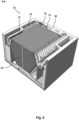
- FIG. 3 illustrates a heat recovery ventilation unit 10 without a front side.
- figure 3 shows how the heat recovery ventilation unit 10 would be view by a technician removing the front side making a polygonal heat exchanger 20.
- a topside 104 comprises a first and second inlets 42, 52 and first and second outlets 44, 54.
- FIGS. 4-9 discloses the housing 30 formed substantially of insulation material.
- Fig. 4 illustrates cross-section A-A of Fig. 3 .
- the first airstream pathway 40 and the second airstream pathway 50 is marked with arrows.
- the first and second filters 12, 14 are partially shown.
- the filters 12,14 can be installed/removed by simply sliding the filters into/out of the housing 30.
- the heat recovery ventilation unit 10 comprises two pre-heater sub-assemblies 16 to illustrate the positioning of the units.
- the pre-heater sub-assembly 16 along the second airstream pathway 50 can be installed/removed by simply sliding the pre-heater sub-assembly 16 into/out of the housing 30.
- the installation/removal of the pre-heater sub-assembly 16 along the first airstream pathway 40 requires modification of the pre-heater sub-assembly 16 to be installed/removed. This is described in greater detail in the description of figure 12 .
- Fig. 5-6 illustrates cross-section B-B and C-C of Fig. 3 .
- the cross-section discloses the housings 30 defining a bypass channel 32 defining a bypass airstream pathway bypassing the polygonal heat exchanger 20.
- the polygonal heat exchanger 20 form a side of the bypass channel 32 which makes the bypass channel 32 accessible when removing the polygonal heat exchanger 20 and this enables the distance between the backside 100 and front side 102 to be reduced.
- the first filter 12 and optionally the pre-heater sub-assembly 16 are positioned upstream to the bypass channel 32 and the polygonal heat exchanger 20.
- Fig. 7 illustrates cross-section D-D of Fig. 3 .
- the cross-section discloses both the first ventilator 22 and the second ventilator 24.
- the airstream swap unit 60 has an exchanger section 72 facing the polygonal heat exchanger 20 and a bypass section 70 facing the bypass channel 32.
- the actuator 74 is positioned at the bypass section 70 to avoid condensation on the actuator 74.
- the actuator 74 controls whether the airstream swap unit 60 is at a heat recovery position 62, where the bypass airstream pathway 34 is blocked, or at a bypass position 64, where the first airstream pathway 50 is blocked.
- Fig. 8 illustrates cross-section E-E of Fig. 3 and discloses a bottom of the housing 30 comprising a first condensation outlet 36 and second condensation outlet 38.
- the figure shows the first outlet 44" of the first outlet manifold 82 next to the first ventilator 22, which would be positioned above the first outlet 44", see figure 7 .
- the figure further shows the second outlet 54" of the second outlet manifold 84 next to the second ventilator 24 which would be positioned above the first outlet 44", see figure 7 .
- Fig. 9 illustrates cross-section F-F of Fig. 3 showing the bypass channel 32 defined by the housing 30.
- the first airstream pathway 40 is marked before and after the bypass channel 32 defining the bypass airstream pathway 34.
- the airstream swap unit 60 controls whether the polygonal heat exchanger 20 is bypassed or not.
- the marked box is discussed in greater detail in fig. 12A as the shown pre-heater sub-assembly 16 cannot be installed through the first inlet 42 shown in figure 3 .
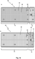
- Fig. 10 illustrates an airstream swap unit 60.
- the airstream swap unit 60 is adapted to be positioned downstream to the polygonal heat exchanger 20 and the bypass airstream pathway 32.
- the airstream swap unit 60 is configurable between a heat recovery position 62, where the bypass airstream pathway 34 is blocked, and a bypass position 64, where the first airstream pathway 50 is blocked.
- the airstream swap unit 60 comprises a stationary grate 66 and a slidable grate 68.
- the grates 66, 68 comprising a series of complementary apertures 69 at a bypass section 70 for facing the bypass channel 32 and at an exchanger section 72 for facing a side of the polygonal heat exchanger 20.
- the apertures 69 are offset between the bypass section 70 and the exchanger section 72 to achieve the following effect wherein
- the airstream swap unit 60 comprises an actuator 74 adapted for displacing the slidable grate 68 between the heat recovery position 62 ( Fig. 10B ) and the bypass position 64 ( Fig. 10A ).
- the actuator 74 is connected to the bypass section 64 as depending on the airstream along the first airstream pathway 40 condensation may be formed downstream to the polygonal heat exchanger 20 thus the condensation will not be formed on the actuator 74.
- Fig. 11 illustrates the airstream swap unit 60 of figure 10 positioned relative to the polygonal heat exchanger 20.
- the airstream swap unit 60 is positioned along a side of the polygonal heat exchanger 20, this part of the airstream swap unit 60 is the exchanger section 72 and the remaining part is the bypass section 70 to face the bypass channel.
- Fig. 11B discloses that the stationary grate 66 comprises between the exchanger section 72 and bypass section 70 a block part 76 arranged to prevent leak flow.
- the block part 76 extent substantially along a front side or a backside of the polygonal heat exchanger 20, which further decreases the risk of leak flow.
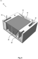
- Fig. 12 illustrates a pre-heater sub-assembly 16.
- the pre-heater sub-assembly 16 is designed such that the pre-heater sub-assembly 16 can be in the chamber shown in fig. 12C and marked box in figure 9 .
- the first filter 12 and the polygonal heat exchanger 20 is removed from the heat recovery ventilation unit 10 before the pre-heater sub-assembly 16 is inserted into chamber.
- Figure 12A and 12B discloses that the pre-heater sub-assembly 16 comprises a heater element 18, heater element holder and upper and lower flexible parts 19I,19II extending from opposite ends of the heater element holder.
- the upper and lower flexible parts 19I,19II are adapted to be wedged between sides of a housing 30 as shown in figure 12C .
- the housing 30 may be adapted to engage ends of the upper and lower flexible parts 19I,19II.
- the upper and lower flexible parts 19I,19II are flexible to achieve a spring force such that a biasing force is established between the upper and lower flexible parts 19I,19II thereby securing the pre-heater sub-assembly 16.
- the upper flexible part 191 comprises a bent defining a foot adapted to engage a slit formed in the housing.
- the pre-heater sub-assembly 16 enables that the first airstream pathway 40 and the second airstream 50 can be used for outdoor air/supply airstream and extract air/exhaust airstream in the cases where pre-heating is required.
Landscapes
- Engineering & Computer Science (AREA)
- Chemical & Material Sciences (AREA)
- Combustion & Propulsion (AREA)
- Mechanical Engineering (AREA)
- General Engineering & Computer Science (AREA)
- Heat-Exchange Devices With Radiators And Conduit Assemblies (AREA)
- Central Air Conditioning (AREA)
Claims (12)
- Wärmerückgewinnungsbelüftungseinheit (10), umfassend- einen polygonalen Wärmetauscher (20) und ein Gehäuse (30), wobei der polygonale Wärmetauscher (20) und das Gehäuse (30) Folgendes definieren:- einen ersten Einlass (42) und einen ersten Auslass (44), die einen ersten Luftstromweg (40) von dem ersten Einlass (42) zu dem ersten Auslass (44) durch den polygonalen Wärmetauscher (20) definieren;- einen zweiten Einlass (52) und einen zweiten Auslass (54), die einen zweiten Luftstromweg (50) von dem zweiten Einlass (52) zu dem zweiten Auslass (54) durch den polygonalen Wärmetauscher (20) definieren;- wobei das Gehäuse (30) ferner umfasst:- einen Bypasskanal (32), der angeordnet ist, um den polygonalen Wärmetauscher (20) entlang des ersten Luftstromwegs (40) zu umgehen, wodurch ein Bypassluftstromweg (34) definiert wird,- eine Luftstromaustauscheinheit (60) stromabwärts des polygonalen Wärmetauschers (20) und des Bypassluftstromweges (32), wobei die Luftstromaustauscheinheit (60) konfigurierbar ist zwischeneiner Wärmerückgewinnungsposition (62), in der der Bypassluftstromweg (34) blockiert ist, undeiner Bypassposition (64), in der der erste Luftstromweg (50) blockiert ist,dadurch gekennzeichnet, dassdas Gehäuse (30) im Wesentlichen durch Isolationsmaterial gebildet ist, unddie Luftstromaustauscheinheit (60) ein stationäres Gitter (66) und ein verschiebbares Gitter (68) umfasst, wobei die Gitter (66, 68) eine Reihe komplementärer Öffnungen (69) an einem dem Bypasskanal (32) zugewandten Bypassabschnitt (70) und an einem einer Seite des polygonalen Wärmetauschers (20) zugewandten Austauschabschnitt (72) umfassen, wobei die Öffnungen (69) zwischen dem Bypassabschnitt (70) und dem Austauschabschnitt (72) versetzt sind, wobei- in der Wärmerückgewinnungsposition (62) das verschiebbare Gitter (68) so positioniert ist, dass sich die Öffnungen (69) an dem Wärmetauscherabschnitt (72) überlappen und die Öffnungen (69) an dem Bypassabschnitt (70) blockiert sind, und- in der Bypassposition (64) das verschiebbare Gitter (68) so positioniert ist, dass sich die Öffnungen (69) an dem Bypassabschnitt (70) überlappen und die Öffnungen (69) an dem Austauschabschnitt (72) blockiert sind.
- Wärmerückgewinnungsbelüftungseinheit (10) nach Anspruch 1, wobei das stationäre Gitter (66) zwischen dem Austauschabschnitt (72) und dem Bypassabschnitt (70) ein Blockteil (76) umfasst, das so angeordnet ist, dass es Leckströme verhindert.
- Wärmerückgewinnungsbelüftungseinheit (10) nach Anspruch 2, wobei sich der Blockteil (76) im Wesentlichen entlang einer Vorderseite oder einer Rückseite des polygonalen Wärmetauschers (20) erstreckt.
- Wärmerückgewinnungsbelüftungseinheit (10) nach einem der Ansprüche 1-3, wobei die Luftstromaustauscheinheit (60) einen Aktor (74) umfasst, der zum Verschieben des verschiebbaren Gitters (68) angepasst ist.
- Wärmerückgewinnungsbelüftungseinheit (10) nach Anspruch 4, wobei der Aktor (74) mit dem Bypassabschnitt (64) verbunden ist.
- Wärmerückgewinnungsbelüftungseinheit (10) nach einem der Ansprüche 1-5, wobei der polygonale Wärmetauscher (20) eine Seite des Bypasskanals (32) bildet.
- Wärmerückgewinnungsbelüftungseinheit (10) nach einem der Ansprüche 1-6, wobei die Wärmerückgewinnungsbelüftungseinheit (10) einen ersten Belüfter (22) stromabwärts des polygonalen Wärmetauschers (20) entlang des ersten Luftstromwegs (40) und einen zweiten Belüfter (24) stromabwärts des polygonalen Wärmetauschers (20) entlang des zweiten Luftstromwegs (50) umfasst.
- Wärmerückgewinnungsbelüftungseinheit (10) nach einem der Ansprüche 1-7, wobei die Wärmerückgewinnungsbelüftungseinheit (10) Folgendes umfasst:- einen ersten Einlassverteiler (80) mit zwei oder mehreren ersten Einlässen (42), die Teil des ersten Luftstromwegs (40) stromaufwärts des polygonalen Wärmetauschers (20) bilden, und/oder- einen ersten Auslassverteiler (82) mit zwei oder mehreren ersten Auslässen (44), die einen Teil des ersten Luftstromweges (40) stromabwärts des polygonalen Wärmetauschers (20) bilden; und/oder- einen zweiten Einlassverteiler (84) mit zwei oder mehreren zweiten Einlässen (52), die Teil des zweiten Luftstromwegs (50) stromaufwärts des polygonalen Wärmetauschers (20) bilden, und/oder- einen zweiten Auslassverteiler (86) mit zwei oder mehreren zweiten Auslässen (54), die einen Teil des zweiten Luftstromweges (50) stromabwärts des polygonalen Wärmetauschers (20) bilden.
- Wärmerückgewinnungsbelüftungseinheit (10) nach einem von Anspruch 8, wobei einer oder mehrere der zwei oder mehreren Einlässe (42, 52) und/oder der eine oder die mehreren der zwei oder mehreren Auslässe (44, 54) teilweise in das Gehäuse (30) eingeschnitzt sind.
- Wärmerückgewinnungsbelüftungseinheit (10) nach einem der Ansprüche 1-9, wobei die Wärmerückgewinnungsbelüftungseinheit (10) ein erstes Filter (12) stromaufwärts des polygonalen Wärmetauschers (20) und des Bypasskanals (34) entlang des ersten Luftstromwegs (40) und ein zweites Filter (14) stromaufwärts des polygonalen Wärmetauschers (20) entlang des zweiten Luftstromwegs (50) umfasst.
- Wärmerückgewinnungsbelüftungseinheit (10) nach einem der Ansprüche 1-10, wobei die Wärmerückgewinnungsbelüftungseinheit (10) Folgendes umfasst- eine Vorwärmerunteranordnung (16) stromaufwärts des polygonalen Wärmetauschers (20) und des Bypasskanals (32) entlang des ersten Luftstromweges (40),- oder eine Vorwärmerunteranordnung (16) stromaufwärts des polygonalen Wärmetauschers (20) entlang des zweiten Luftstromweges (50),wobei die Vorwärmerunteranordnung (16) ein Heizelement (18), ein oberes und unteres flexibles Teil (191, 1911) umfasst, die sich von gegenüberliegenden Enden der Vorwärmerunteranordnung (16) erstrecken, wobei das obere und das untere flexible Teil (191, 1911) so angeordnet sind, dass sie zwischen Seiten des Gehäuses (30) verkeilt sind.
- Wärmerückgewinnungsbelüftungseinheit (10) nach einem der Ansprüche 1-11, wobei die Wärmerückgewinnungsbelüftungseinheit (10) eine Steuerung (90) umfasst, die derart konfigurierbar ist, dass sowohl der erste Luftstromweg (40) als auch der zweite Luftstromweg (50) für Außenluft/Zuluftstrom und Abluft/Austrittsluftstrom verwendet werden können.
Priority Applications (1)
| Application Number | Priority Date | Filing Date | Title |
|---|---|---|---|
| EP21196641.1A EP4148335B1 (de) | 2021-09-14 | 2021-09-14 | Wärmerückgewinnungsbelüftungseinheit, luftstromaustauscheinheit und vorwärmeranordnung |
Applications Claiming Priority (1)
| Application Number | Priority Date | Filing Date | Title |
|---|---|---|---|
| EP21196641.1A EP4148335B1 (de) | 2021-09-14 | 2021-09-14 | Wärmerückgewinnungsbelüftungseinheit, luftstromaustauscheinheit und vorwärmeranordnung |
Publications (2)
| Publication Number | Publication Date |
|---|---|
| EP4148335A1 EP4148335A1 (de) | 2023-03-15 |
| EP4148335B1 true EP4148335B1 (de) | 2024-11-06 |
Family
ID=77774694
Family Applications (1)
| Application Number | Title | Priority Date | Filing Date |
|---|---|---|---|
| EP21196641.1A Active EP4148335B1 (de) | 2021-09-14 | 2021-09-14 | Wärmerückgewinnungsbelüftungseinheit, luftstromaustauscheinheit und vorwärmeranordnung |
Country Status (1)
| Country | Link |
|---|---|
| EP (1) | EP4148335B1 (de) |
Family Cites Families (5)
| Publication number | Priority date | Publication date | Assignee | Title |
|---|---|---|---|---|
| CN1226570C (zh) * | 2001-03-30 | 2005-11-09 | 大金工业株式会社 | 换气装置及换气装置的组装方法 |
| KR100617085B1 (ko) * | 2005-02-22 | 2006-08-30 | 엘지전자 주식회사 | 초박형 환기장치 |
| GB2562674B (en) * | 2013-02-08 | 2019-03-06 | Polypipe Ltd | Mechanical ventilation and heat recovery unit and system |
| GB2522629B (en) * | 2014-01-29 | 2019-10-16 | Nuaire Ltd | A heat exchanger bypass apparatus |
| EP3696469B1 (de) * | 2019-02-13 | 2021-06-02 | Airmaster A/S | Hybrides lüftungssystem |
-
2021
- 2021-09-14 EP EP21196641.1A patent/EP4148335B1/de active Active
Also Published As
| Publication number | Publication date |
|---|---|
| EP4148335A1 (de) | 2023-03-15 |
Similar Documents
| Publication | Publication Date | Title |
|---|---|---|
| CN113124465B (zh) | 一种厨房空气调节系统 | |
| CN102155794B (zh) | 用于炉的集管箱、包括集管箱的炉及构成该炉的方法 | |
| KR101578528B1 (ko) | 바이패스 유로를 별도로 구비한 열회수 환기장치 | |
| US10852071B2 (en) | Method of operating an energy recovery system | |
| EP3542870B1 (de) | Belüftungssystem für ein gebäude mit einer rauchabzugsfunktionalität und verfahren zum betreiben dieses systems | |
| US7565924B2 (en) | Pressure equilizing system | |
| KR20150108046A (ko) | 바이패스 덕트를 구비한 열회수형 환기 시스템 | |
| CN105605678A (zh) | 一种送风装置、空调设备以及空调设备的送风方法 | |
| US11690197B2 (en) | Airflow management system that can be fitted to an electrical enclosure | |
| EP4023958B1 (de) | Lufthandhabungseinheit | |
| EP2905548B1 (de) | Wärmetauscherbypassvorrichtung | |
| DE202007001644U1 (de) | Modular aufgebaute Lüftungseinrichtung für den Einsatz im Reinraum | |
| EP4148335A1 (de) | Wärmerückgewinnungsbelüftungseinheit, luftstromaustauscheinheit und vorwärmeranordnung | |
| DK176577B1 (da) | Krydsvarmeveksler samt fremgangsmåde til drift af denne | |
| US11435109B2 (en) | Ventilator | |
| KR20230156671A (ko) | 열회수형 환기장치 | |
| KR101708838B1 (ko) | 전산실 통신장비용 급배기 일체형 냉방기 및 이를 구비한 냉방시스템 | |
| EP2767777B1 (de) | Wärmetauschervorrichtung zur Verwendung in einer Lüftungseinheit und Verfahren zum Betrieb desselben | |
| CN111397339B (zh) | 一种组合立式汽车零部件烘干炉及其使用方法 | |
| EP3469268B1 (de) | Verfahren und vorrichtung für energieeffiziente belüftungssysteme für gebäude | |
| CN116538585B (zh) | 适用双轴马达双风扇的节能立式空气循环机 | |
| US20200284429A1 (en) | Blower assembly for gas-burning appliance | |
| CN205351674U (zh) | 一种送风装置及空调设备 | |
| JP2015129621A (ja) | 熱交換型換気システム | |
| US5697210A (en) | Fully-fired combined gas turbine with independently operable boiler and ventilator |
Legal Events
| Date | Code | Title | Description |
|---|---|---|---|
| PUAI | Public reference made under article 153(3) epc to a published international application that has entered the european phase |
Free format text: ORIGINAL CODE: 0009012 |
|
| STAA | Information on the status of an ep patent application or granted ep patent |
Free format text: STATUS: THE APPLICATION HAS BEEN PUBLISHED |
|
| AK | Designated contracting states |
Kind code of ref document: A1 Designated state(s): AL AT BE BG CH CY CZ DE DK EE ES FI FR GB GR HR HU IE IS IT LI LT LU LV MC MK MT NL NO PL PT RO RS SE SI SK SM TR |
|
| STAA | Information on the status of an ep patent application or granted ep patent |
Free format text: STATUS: REQUEST FOR EXAMINATION WAS MADE |
|
| 17P | Request for examination filed |
Effective date: 20230911 |
|
| RAP3 | Party data changed (applicant data changed or rights of an application transferred) |
Owner name: DANTHERM DENMARK A/S |
|
| RBV | Designated contracting states (corrected) |
Designated state(s): AL AT BE BG CH CY CZ DE DK EE ES FI FR GB GR HR HU IE IS IT LI LT LU LV MC MK MT NL NO PL PT RO RS SE SI SK SM TR |
|
| GRAP | Despatch of communication of intention to grant a patent |
Free format text: ORIGINAL CODE: EPIDOSNIGR1 |
|
| STAA | Information on the status of an ep patent application or granted ep patent |
Free format text: STATUS: GRANT OF PATENT IS INTENDED |
|
| INTG | Intention to grant announced |
Effective date: 20240522 |
|
| GRAS | Grant fee paid |
Free format text: ORIGINAL CODE: EPIDOSNIGR3 |
|
| GRAA | (expected) grant |
Free format text: ORIGINAL CODE: 0009210 |
|
| STAA | Information on the status of an ep patent application or granted ep patent |
Free format text: STATUS: THE PATENT HAS BEEN GRANTED |
|
| AK | Designated contracting states |
Kind code of ref document: B1 Designated state(s): AL AT BE BG CH CY CZ DE DK EE ES FI FR GB GR HR HU IE IS IT LI LT LU LV MC MK MT NL NO PL PT RO RS SE SI SK SM TR |
|
| REG | Reference to a national code |
Ref country code: GB Ref legal event code: FG4D |
|
| REG | Reference to a national code |
Ref country code: CH Ref legal event code: EP |
|
| REG | Reference to a national code |
Ref country code: DE Ref legal event code: R096 Ref document number: 602021021311 Country of ref document: DE |
|
| REG | Reference to a national code |
Ref country code: IE Ref legal event code: FG4D |
|
| REG | Reference to a national code |
Ref country code: LT Ref legal event code: MG9D |
|
| REG | Reference to a national code |
Ref country code: NL Ref legal event code: MP Effective date: 20241106 |
|
| PG25 | Lapsed in a contracting state [announced via postgrant information from national office to epo] |
Ref country code: PT Free format text: LAPSE BECAUSE OF FAILURE TO SUBMIT A TRANSLATION OF THE DESCRIPTION OR TO PAY THE FEE WITHIN THE PRESCRIBED TIME-LIMIT Effective date: 20250306 Ref country code: HR Free format text: LAPSE BECAUSE OF FAILURE TO SUBMIT A TRANSLATION OF THE DESCRIPTION OR TO PAY THE FEE WITHIN THE PRESCRIBED TIME-LIMIT Effective date: 20241106 Ref country code: IS Free format text: LAPSE BECAUSE OF FAILURE TO SUBMIT A TRANSLATION OF THE DESCRIPTION OR TO PAY THE FEE WITHIN THE PRESCRIBED TIME-LIMIT Effective date: 20250306 |
|
| PG25 | Lapsed in a contracting state [announced via postgrant information from national office to epo] |
Ref country code: FI Free format text: LAPSE BECAUSE OF FAILURE TO SUBMIT A TRANSLATION OF THE DESCRIPTION OR TO PAY THE FEE WITHIN THE PRESCRIBED TIME-LIMIT Effective date: 20241106 Ref country code: NL Free format text: LAPSE BECAUSE OF FAILURE TO SUBMIT A TRANSLATION OF THE DESCRIPTION OR TO PAY THE FEE WITHIN THE PRESCRIBED TIME-LIMIT Effective date: 20241106 |
|
| REG | Reference to a national code |
Ref country code: AT Ref legal event code: MK05 Ref document number: 1739716 Country of ref document: AT Kind code of ref document: T Effective date: 20241106 |
|
| PG25 | Lapsed in a contracting state [announced via postgrant information from national office to epo] |
Ref country code: BG Free format text: LAPSE BECAUSE OF FAILURE TO SUBMIT A TRANSLATION OF THE DESCRIPTION OR TO PAY THE FEE WITHIN THE PRESCRIBED TIME-LIMIT Effective date: 20241106 |
|
| PG25 | Lapsed in a contracting state [announced via postgrant information from national office to epo] |
Ref country code: ES Free format text: LAPSE BECAUSE OF FAILURE TO SUBMIT A TRANSLATION OF THE DESCRIPTION OR TO PAY THE FEE WITHIN THE PRESCRIBED TIME-LIMIT Effective date: 20241106 |
|
| PG25 | Lapsed in a contracting state [announced via postgrant information from national office to epo] |
Ref country code: NO Free format text: LAPSE BECAUSE OF FAILURE TO SUBMIT A TRANSLATION OF THE DESCRIPTION OR TO PAY THE FEE WITHIN THE PRESCRIBED TIME-LIMIT Effective date: 20250206 |
|
| PG25 | Lapsed in a contracting state [announced via postgrant information from national office to epo] |
Ref country code: LV Free format text: LAPSE BECAUSE OF FAILURE TO SUBMIT A TRANSLATION OF THE DESCRIPTION OR TO PAY THE FEE WITHIN THE PRESCRIBED TIME-LIMIT Effective date: 20241106 Ref country code: GR Free format text: LAPSE BECAUSE OF FAILURE TO SUBMIT A TRANSLATION OF THE DESCRIPTION OR TO PAY THE FEE WITHIN THE PRESCRIBED TIME-LIMIT Effective date: 20250207 Ref country code: AT Free format text: LAPSE BECAUSE OF FAILURE TO SUBMIT A TRANSLATION OF THE DESCRIPTION OR TO PAY THE FEE WITHIN THE PRESCRIBED TIME-LIMIT Effective date: 20241106 |
|
| PG25 | Lapsed in a contracting state [announced via postgrant information from national office to epo] |
Ref country code: PL Free format text: LAPSE BECAUSE OF FAILURE TO SUBMIT A TRANSLATION OF THE DESCRIPTION OR TO PAY THE FEE WITHIN THE PRESCRIBED TIME-LIMIT Effective date: 20241106 |
|
| PG25 | Lapsed in a contracting state [announced via postgrant information from national office to epo] |
Ref country code: RS Free format text: LAPSE BECAUSE OF FAILURE TO SUBMIT A TRANSLATION OF THE DESCRIPTION OR TO PAY THE FEE WITHIN THE PRESCRIBED TIME-LIMIT Effective date: 20250206 |
|
| PG25 | Lapsed in a contracting state [announced via postgrant information from national office to epo] |
Ref country code: SM Free format text: LAPSE BECAUSE OF FAILURE TO SUBMIT A TRANSLATION OF THE DESCRIPTION OR TO PAY THE FEE WITHIN THE PRESCRIBED TIME-LIMIT Effective date: 20241106 |
|
| PG25 | Lapsed in a contracting state [announced via postgrant information from national office to epo] |
Ref country code: DK Free format text: LAPSE BECAUSE OF FAILURE TO SUBMIT A TRANSLATION OF THE DESCRIPTION OR TO PAY THE FEE WITHIN THE PRESCRIBED TIME-LIMIT Effective date: 20241106 |
|
| PG25 | Lapsed in a contracting state [announced via postgrant information from national office to epo] |
Ref country code: EE Free format text: LAPSE BECAUSE OF FAILURE TO SUBMIT A TRANSLATION OF THE DESCRIPTION OR TO PAY THE FEE WITHIN THE PRESCRIBED TIME-LIMIT Effective date: 20241106 |
|
| PG25 | Lapsed in a contracting state [announced via postgrant information from national office to epo] |
Ref country code: RO Free format text: LAPSE BECAUSE OF FAILURE TO SUBMIT A TRANSLATION OF THE DESCRIPTION OR TO PAY THE FEE WITHIN THE PRESCRIBED TIME-LIMIT Effective date: 20241106 |
|
| PG25 | Lapsed in a contracting state [announced via postgrant information from national office to epo] |
Ref country code: SK Free format text: LAPSE BECAUSE OF FAILURE TO SUBMIT A TRANSLATION OF THE DESCRIPTION OR TO PAY THE FEE WITHIN THE PRESCRIBED TIME-LIMIT Effective date: 20241106 |
|
| PG25 | Lapsed in a contracting state [announced via postgrant information from national office to epo] |
Ref country code: CZ Free format text: LAPSE BECAUSE OF FAILURE TO SUBMIT A TRANSLATION OF THE DESCRIPTION OR TO PAY THE FEE WITHIN THE PRESCRIBED TIME-LIMIT Effective date: 20241106 |
|
| PG25 | Lapsed in a contracting state [announced via postgrant information from national office to epo] |
Ref country code: IT Free format text: LAPSE BECAUSE OF FAILURE TO SUBMIT A TRANSLATION OF THE DESCRIPTION OR TO PAY THE FEE WITHIN THE PRESCRIBED TIME-LIMIT Effective date: 20241106 |
|
| REG | Reference to a national code |
Ref country code: DE Ref legal event code: R097 Ref document number: 602021021311 Country of ref document: DE |
|
| PG25 | Lapsed in a contracting state [announced via postgrant information from national office to epo] |
Ref country code: SE Free format text: LAPSE BECAUSE OF FAILURE TO SUBMIT A TRANSLATION OF THE DESCRIPTION OR TO PAY THE FEE WITHIN THE PRESCRIBED TIME-LIMIT Effective date: 20241106 |
|
| PLBE | No opposition filed within time limit |
Free format text: ORIGINAL CODE: 0009261 |
|
| STAA | Information on the status of an ep patent application or granted ep patent |
Free format text: STATUS: NO OPPOSITION FILED WITHIN TIME LIMIT |
|
| 26N | No opposition filed |
Effective date: 20250807 |
|
| PGFP | Annual fee paid to national office [announced via postgrant information from national office to epo] |
Ref country code: DE Payment date: 20251114 Year of fee payment: 5 |
|
| REG | Reference to a national code |
Ref country code: CH Ref legal event code: H13 Free format text: ST27 STATUS EVENT CODE: U-0-0-H10-H13 (AS PROVIDED BY THE NATIONAL OFFICE) Effective date: 20260504 |