EP4148273B1 - Flüssigkeitspumpe - Google Patents
Flüssigkeitspumpe Download PDFInfo
- Publication number
- EP4148273B1 EP4148273B1 EP22190382.6A EP22190382A EP4148273B1 EP 4148273 B1 EP4148273 B1 EP 4148273B1 EP 22190382 A EP22190382 A EP 22190382A EP 4148273 B1 EP4148273 B1 EP 4148273B1
- Authority
- EP
- European Patent Office
- Prior art keywords
- fluid
- piston
- inlet
- pump
- tesla
- Prior art date
- Legal status (The legal status is an assumption and is not a legal conclusion. Google has not performed a legal analysis and makes no representation as to the accuracy of the status listed.)
- Active
Links
Images


Classifications
-
- F—MECHANICAL ENGINEERING; LIGHTING; HEATING; WEAPONS; BLASTING
- F04—POSITIVE - DISPLACEMENT MACHINES FOR LIQUIDS; PUMPS FOR LIQUIDS OR ELASTIC FLUIDS
- F04B—POSITIVE-DISPLACEMENT MACHINES FOR LIQUIDS; PUMPS
- F04B15/00—Pumps adapted to handle specific fluids, e.g. by selection of specific materials for pumps or pump parts
- F04B15/06—Pumps adapted to handle specific fluids, e.g. by selection of specific materials for pumps or pump parts for liquids near their boiling point, e.g. under subnormal pressure
- F04B15/08—Pumps adapted to handle specific fluids, e.g. by selection of specific materials for pumps or pump parts for liquids near their boiling point, e.g. under subnormal pressure the liquids having low boiling points
-
- F—MECHANICAL ENGINEERING; LIGHTING; HEATING; WEAPONS; BLASTING
- F04—POSITIVE - DISPLACEMENT MACHINES FOR LIQUIDS; PUMPS FOR LIQUIDS OR ELASTIC FLUIDS
- F04B—POSITIVE-DISPLACEMENT MACHINES FOR LIQUIDS; PUMPS
- F04B39/00—Component parts, details, or accessories, of pumps or pumping systems specially adapted for elastic fluids, not otherwise provided for in, or of interest apart from, groups F04B25/00 - F04B37/00
- F04B39/0005—Component parts, details, or accessories, of pumps or pumping systems specially adapted for elastic fluids, not otherwise provided for in, or of interest apart from, groups F04B25/00 - F04B37/00 adaptations of pistons
- F04B39/0016—Component parts, details, or accessories, of pumps or pumping systems specially adapted for elastic fluids, not otherwise provided for in, or of interest apart from, groups F04B25/00 - F04B37/00 adaptations of pistons with valve arranged in the piston
-
- F—MECHANICAL ENGINEERING; LIGHTING; HEATING; WEAPONS; BLASTING
- F04—POSITIVE - DISPLACEMENT MACHINES FOR LIQUIDS; PUMPS FOR LIQUIDS OR ELASTIC FLUIDS
- F04B—POSITIVE-DISPLACEMENT MACHINES FOR LIQUIDS; PUMPS
- F04B53/00—Component parts, details or accessories not provided for in, or of interest apart from, groups F04B1/00 - F04B23/00 or F04B39/00 - F04B47/00
- F04B53/10—Valves; Arrangement of valves
- F04B53/102—Disc valves
- F04B53/1032—Spring-actuated disc valves
-
- F—MECHANICAL ENGINEERING; LIGHTING; HEATING; WEAPONS; BLASTING
- F04—POSITIVE - DISPLACEMENT MACHINES FOR LIQUIDS; PUMPS FOR LIQUIDS OR ELASTIC FLUIDS
- F04B—POSITIVE-DISPLACEMENT MACHINES FOR LIQUIDS; PUMPS
- F04B53/00—Component parts, details or accessories not provided for in, or of interest apart from, groups F04B1/00 - F04B23/00 or F04B39/00 - F04B47/00
- F04B53/10—Valves; Arrangement of valves
- F04B53/1077—Flow resistance valves, e.g. without moving parts
-
- F—MECHANICAL ENGINEERING; LIGHTING; HEATING; WEAPONS; BLASTING
- F04—POSITIVE - DISPLACEMENT MACHINES FOR LIQUIDS; PUMPS FOR LIQUIDS OR ELASTIC FLUIDS
- F04B—POSITIVE-DISPLACEMENT MACHINES FOR LIQUIDS; PUMPS
- F04B53/00—Component parts, details or accessories not provided for in, or of interest apart from, groups F04B1/00 - F04B23/00 or F04B39/00 - F04B47/00
- F04B53/10—Valves; Arrangement of valves
- F04B53/12—Valves; Arrangement of valves arranged in or on pistons
-
- F—MECHANICAL ENGINEERING; LIGHTING; HEATING; WEAPONS; BLASTING
- F04—POSITIVE - DISPLACEMENT MACHINES FOR LIQUIDS; PUMPS FOR LIQUIDS OR ELASTIC FLUIDS
- F04B—POSITIVE-DISPLACEMENT MACHINES FOR LIQUIDS; PUMPS
- F04B53/00—Component parts, details or accessories not provided for in, or of interest apart from, groups F04B1/00 - F04B23/00 or F04B39/00 - F04B47/00
- F04B53/14—Pistons, piston-rods or piston-rod connections
-
- F—MECHANICAL ENGINEERING; LIGHTING; HEATING; WEAPONS; BLASTING
- F04—POSITIVE - DISPLACEMENT MACHINES FOR LIQUIDS; PUMPS FOR LIQUIDS OR ELASTIC FLUIDS
- F04B—POSITIVE-DISPLACEMENT MACHINES FOR LIQUIDS; PUMPS
- F04B53/00—Component parts, details or accessories not provided for in, or of interest apart from, groups F04B1/00 - F04B23/00 or F04B39/00 - F04B47/00
- F04B53/16—Casings; Cylinders; Cylinder liners or heads; Fluid connections
- F04B53/162—Adaptations of cylinders
-
- F—MECHANICAL ENGINEERING; LIGHTING; HEATING; WEAPONS; BLASTING
- F04—POSITIVE - DISPLACEMENT MACHINES FOR LIQUIDS; PUMPS FOR LIQUIDS OR ELASTIC FLUIDS
- F04B—POSITIVE-DISPLACEMENT MACHINES FOR LIQUIDS; PUMPS
- F04B7/00—Piston machines or pumps characterised by having positively-driven valving
- F04B7/0076—Piston machines or pumps characterised by having positively-driven valving the members being actuated by electro-magnetic means
-
- F—MECHANICAL ENGINEERING; LIGHTING; HEATING; WEAPONS; BLASTING
- F04—POSITIVE - DISPLACEMENT MACHINES FOR LIQUIDS; PUMPS FOR LIQUIDS OR ELASTIC FLUIDS
- F04B—POSITIVE-DISPLACEMENT MACHINES FOR LIQUIDS; PUMPS
- F04B7/00—Piston machines or pumps characterised by having positively-driven valving
- F04B7/02—Piston machines or pumps characterised by having positively-driven valving the valving being fluid-actuated
- F04B7/0266—Piston machines or pumps characterised by having positively-driven valving the valving being fluid-actuated the inlet and discharge means being separate members
-
- F—MECHANICAL ENGINEERING; LIGHTING; HEATING; WEAPONS; BLASTING
- F04—POSITIVE - DISPLACEMENT MACHINES FOR LIQUIDS; PUMPS FOR LIQUIDS OR ELASTIC FLUIDS
- F04B—POSITIVE-DISPLACEMENT MACHINES FOR LIQUIDS; PUMPS
- F04B15/00—Pumps adapted to handle specific fluids, e.g. by selection of specific materials for pumps or pump parts
- F04B15/06—Pumps adapted to handle specific fluids, e.g. by selection of specific materials for pumps or pump parts for liquids near their boiling point, e.g. under subnormal pressure
- F04B15/08—Pumps adapted to handle specific fluids, e.g. by selection of specific materials for pumps or pump parts for liquids near their boiling point, e.g. under subnormal pressure the liquids having low boiling points
- F04B2015/081—Liquefied gases
- F04B2015/0822—Hydrogen
-
- F—MECHANICAL ENGINEERING; LIGHTING; HEATING; WEAPONS; BLASTING
- F05—INDEXING SCHEMES RELATING TO ENGINES OR PUMPS IN VARIOUS SUBCLASSES OF CLASSES F01-F04
- F05C—INDEXING SCHEME RELATING TO MATERIALS, MATERIAL PROPERTIES OR MATERIAL CHARACTERISTICS FOR MACHINES, ENGINES OR PUMPS OTHER THAN NON-POSITIVE-DISPLACEMENT MACHINES OR ENGINES
- F05C2225/00—Synthetic polymers, e.g. plastics; Rubber
- F05C2225/04—PTFE [PolyTetraFluorEthylene]
-
- F—MECHANICAL ENGINEERING; LIGHTING; HEATING; WEAPONS; BLASTING
- F05—INDEXING SCHEMES RELATING TO ENGINES OR PUMPS IN VARIOUS SUBCLASSES OF CLASSES F01-F04
- F05C—INDEXING SCHEME RELATING TO MATERIALS, MATERIAL PROPERTIES OR MATERIAL CHARACTERISTICS FOR MACHINES, ENGINES OR PUMPS OTHER THAN NON-POSITIVE-DISPLACEMENT MACHINES OR ENGINES
- F05C2253/00—Other material characteristics; Treatment of material
- F05C2253/12—Coating
Definitions
- This disclosure relates to a fluid pump and use thereof.
- US patent US5509792A discloses a reciprocal type of pump structure wherein a piston has a linear function actuated by a pair of coils energized alternately and includes a plurality of tapered flutes.
- a check valve in an outlet of the structure which stretches to open said outlet under the impact of expelled fluids and of its own volition retracts to the closed position immediately upon the cessation of fluids being expelled.
- a fluid pump as set out in claims 1 to 6.
- a fuel delivery system as set out in claims 7 and 8.
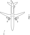
- FIG. 1 A hydrogen-fuelled airliner is illustrated in Figure 1 .
- the airliner 101 is of substantially conventional tube-and-wing twinjet configuration with a central fuselage 102 and substantially identical underwing-mounted turbofan engines 103.
- the turbofan engines 103 may for example be geared turbofan engines.
- a hydrogen storage tank 104 located in the fuselage 104 for a hydrogen fuel supply is connected with core gas turbines 105 in the turbofan engines 103 via a fuel delivery system.
- the hydrogen storage tank 104 is a cryogenic hydrogen storage tank that stores the hydrogen fuel in a liquid state, in a specific example at 20 K.
- the hydrogen fuel may be pressurised to between around from 1 to 3 bar, for example around 2 bar.
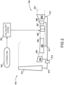
- FIG. 2 A block diagram identifying the flow of hydrogen fuel is shown in Figure 2 .
- Hydrogen fuel is obtained from a hydrogen storage tank 104 by a fuel delivery system 201 and is supplied to a core of a gas turbine 105. Only one of the gas turbines is shown for clarity.
- the gas turbine 105 is a simple cycle gas turbine engine. In other embodiments, complex cycles may be implemented via fuel-cooling of the gas path.
- the gas turbine 105 comprises, in axial flow series, a low-pressure compressor 202, an interstage duct 203, a high-pressure compressor 204, a diffuser 205, a fuel injection system 206, a combustor 207, a high-pressure turbine 208, a low-pressure turbine 209, and a core nozzle 210.
- the fuel injection system 206 may be a lean direct fuel injection system.
- the high-pressure compressor 204 is driven by the high-pressure turbine 208 via a first shaft 211 and the low-pressure compressor 202 is driven by the low-pressure turbine 209 via a second shaft 212.
- the gas turbine 105 may comprise more than two shafts.
- the low-pressure turbine 209 also drives a fan 213 via a reduction gearbox 214.
- the reduction gearbox 214 receives an input drive from the second shaft 212 and provides an output drive to the fan 213 via a fan shaft 215.
- the reduction gearbox 214 may be an epicyclic gearbox, which may be of planetary, star or compound configuration. In further alternatives, the reduction gearbox 214 may be a layshaft-type reduction gearbox or another type of reduction gearbox. It will also be appreciated that the principles disclosed herein may be applied to a direct-drive type turbofan engine, i.e. in which there is no reduction gearbox between the low-pressure turbine 209 and the fan 213.
- the fuel delivery system 201 is configured to obtain hydrogen fuel from the hydrogen storage tank 104 and provide the fuel to the fuel injection system 206.
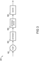
- Figure 3 is a block diagram illustrating the fuel delivery system 201 in greater detail.
- the fuel delivery system 201 comprises a pump 301, a vaporiser 303, a metering device 302 and a heater 304 for heating the hydrogen fuel to an injection temperature for the fuel injection system 206.
- a vent system (not shown) may be included in the fuel delivery system 201 close to the fuel injection system 206 to vent hydrogen fuel should a rapid shut-off be required, for example in response to a shaft-break event. It is envisaged that the vent system may vent the excess hydrogen fuel into the bypass duct of the turbofan engine 103, or alternatively vent it outside of the nacelle of the engine 103.
- An igniter may be provided to flare off the excess hydrogen in a controlled manner.
- the fuel delivery system may deliver fuel to an aircraft powerplant other than a gas turbine engine, for example a fuel cell.
- the fuel delivery system may deliver fuel to an aircraft powerplant, which may comprise a fuel cell and/or a gas turbine engine.
- the gas turbine engine may for example drive a turbofan engine or a turboprop engine or may be used as a generator for generating electricity for propulsion or otherwise.
- FIGs 4a and 4b illustrate schematically an embodiment of the pump 301 for the fuel delivery system 201, which is not in accordance with the present invention.
- the pump 301 comprises a chamber 401 defining a cylinder 406 in which a piston 407 is slidably disposed.
- the chamber 401 comprises an inlet 402 at one end of the chamber 401 and an outlet 403 at an opposing end of the chamber 401.
- the outlet 403 comprises a non-return valve 404.
- the piston 407 comprises a plurality of Tesla valves 408. Each Tesla valve 408 is in fluid communication with the inlet 402.
- the pump 301 is configured to pump fluid, for example a cryogenic fluid such as hydrogen or helium or a supercritical fluid, from the inlet 402 to the outlet 403 by reciprocation of the piston 407 within the cylinder 406.
- the piston 407 comprises a plurality of Tesla valves 408, although in general terms one or more Tesla valves may be used.
- the inlet 402 is at the top of the pump 301 and the outlet 403 is at the bottom, although the pump 301 may operate in other orientations.
- the outlet 403 comprises a biasing mechanism 409 to maintain the valve 404 closed below a preset pressure.
- the biasing mechanism 409 may be adjustable to allow the present pressure to be set. This may for example be achieved by selecting a spring with a spring constant defining a desired force to maintain the valve 404 closed.
- the biasing mechanism may be pneumatically, hydraulically or electrically controllable.
- An adjustable biasing mechanism may for example comprise a solenoid, which in some examples may be superconducting when pumping cryogenic fluids.
- the piston 407 is driven downwards towards the bottom of the cylinder as depicted in Figure 4b .
- the fluid in the lower part of the cavity 405 increases in pressure.
- the non-return valve 404 begins to allow fluid to flow through the outlet 403 as the piston 407 continues to move downwards, and the high pressure fluid exits the pump 301 through the outlet 403.
- the Tesla valves 408 (described in further detail below in relation to Figure 6 ) limit fluid from flowing back through the piston 407 as the piston 407 is driven downwards by flow through the Tesla valves having a preferred flow direction indicated by the arrows T.
- the flow rate of fluid through the pump 301 is determined by the driving speed of the piston 407, i.e. the faster the piston reciprocates in the cylinder the greater the overall flow rate will be.
- a sufficient amount of fluid is required to enter the Tesla valves 408 in the upwards direction to create adequate downwards pressure by redirecting the fluid to mitigate backflow. Only a small portion of the fluid may therefore return to the top of the cavity 405 as the piston 407 is driven downwards.
- the Tesla valves 408 then allow fluid to move more freely into the lower part of the cavity in the preferred flow direction T.
- the piston 407 may be driven in various ways. Options may for example include linear actuators (electrical linear motors) or mechanical driving arrangements driving the piston either electrically via rotating parts or via linear actuators located outside or inside the pump housing.
- a nutating disk engine may for example be driven electrically or mechanically, or may be driven by expanding hot or cold gases or by combustion of hydrogen. Direct mechanical coupling with a prime mover may be used, with optional mechanical gearing to control the rotating speeds.
- the piston may be formed of materials such as steel, e.g. stainless steel, a nickel-base alloy, e.g. an Inconel (RTM), or composite materials.
- the Tesla valves 408 may be formed of similar materials to the surrounding piston.
- the piston 407 may comprise an outer surface coating or layer of a low friction material such as polytetrafluoroethene (PTFE) or another dry lubricant layer such as graphite.
- PTFE polytetrafluoroethene
- the inner side of the chamber 406 may also be coated with a similar low coefficient material.
- the piston 407 may comprise a PTFE outer layer, an inner stainless steel shell and Tesla valves formed of an Inconel alloy.
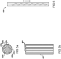
- Figure 5 illustrates an end view and a sectional view of the example piston 407 comprising a plurality of Tesla valves 408, which is not in accordance with the present invention.
- six Tesla valves 408a-f are provided in the piston 407 in a parallel rotationally symmetric arrangement with the Tesla valves 408a-f in an annular arrangement.
- Using a plurality of Tesla valves in a parallel arrangement allows for a greater fluid flow rate through the pump 301.
- the Tesla valves may be arranged in different configurations and greater or fewer than six may be used.
- Figure 6 illustrates a sectional diagram of an example Tesla valve 408, showing the internal arrangement of the valve that allows for a preferred fluid flow direction T. In this orientation the fluid moves with little resistance in the flow direction T but will have much higher resistance in the reverse direction due to flow in the reverse direction causing turbulent flow within the valve 408.
- FIG 7 illustrates schematically an embodiment of the pump 301' comprising Tesla valves, in which the fluid pump 301' has an 'H' configuration rather than the linear configuration of the example in Figures 4a and 4b .
- the pump 301' comprises a chamber 701 having a cavity 706 comprising a cylinder 709, a piston 712 being slidably disposed within the cylinder, and a Tesla valve 713, 714.
- the pump 301' comprises a first inlet 704, a first outlet 707, a second inlet 705 and a second outlet 708.
- the first outlet 707 comprises a first non-return valve 710 and the second outlet 708 comprises a second non-return valve 711.
- a first fluid passage 702 extends between the first inlet 704 and the first outlet 707.
- a second fluid passage 703 extends between the second inlet 705 and the second outlet 708.
- a first Tesla valve 713 is in fluid communication with the first inlet 704 and a second Tesla valve 714 is in fluid communication with the second inlet 705.
- the cylinder 709 within which the piston 712 is provided extends between the first fluid passage 702 and the second fluid passage 703. Because in this example the piston reciprocates between the first and second passages, fluid flow is alternately pumped through the first and second outlets 707, 708, allowing for a more continuous flow of fluid through the pump 301' compared to the pump 301 of Figures 4a and 4b .
- the piston is driven from left to right as shown by arrow P, fluid enters the first fluid passage 702 through the first Tesla valve 713 via the first inlet 704 and is compressed in the second fluid passage 703.
- the Tesla valve 714 in fluid communication with the second inlet 705 prevents backflow, provided a minimum fluid flow rate passing through the pump 301' is achieved.
- the second non-return valve 711 opens and high-pressure fluid exits the passage 703 through the second outlet 708.
- the piston 712 then travels from right to left, the process repeats for the first passage 702, causing fluid to exit via the first outlet 707 and be drawn into the second passage 703 via the second inlet 705.
- Tesla valves 713, 714 are located in the respective first and second passages 702, 703 at or proximate the respective first and second inlets 704, 705. These Tesla valves, allowing fluid to flow more easily in one direction than an opposing direction, effectively acting as non-return valves.
- further non-return valves may be provided at the first and second inlets 704, 705, which may be in the form of the non-return valve in the example shown in Figures 4a and 4b .
- Tesla valves may be used as non-return valves for the inlets 704, 705 and the outlets 710, 711, i.e.
- the non-return valve at each outlet may also comprise or be in the form of a Tesla valve.
- the outlets may also comprise a non-return valve of the type described above in relation to Figures 4a and 4b .
- the piston 712 may be similarly coated with a low coefficient material such as PTFE.
- the inner surface of the cylinder 709 may also similarly coated for pumping cryogenic fluids.
- each passage 702, 703 may comprise one or more Tesla valves, for example in an arrangement as shown in Figure 5 .
- the Tesla valves may be provided at the first and second inlets 704, 705 as in the illustration of Figure 7 or may be provided at other points within the first and second passages 702, 703, in each case with a preferred flow direction towards the first and second outlets 710, 711.
- a sufficient flow rate of fluid through the pump 301, 301' mitigates fluid leakage around the piston sides and through the Tesla valves.
- a fluid pump of the type disclosed herein may be used as a fuel pump for a hydrogen-powered turbofan engine in an aircraft.
- the fluid pump may, however, also be used in other applications for pumping fluids, particularly cryogenic fluids.
Landscapes
- Engineering & Computer Science (AREA)
- Mechanical Engineering (AREA)
- General Engineering & Computer Science (AREA)
- Chemical & Material Sciences (AREA)
- Combustion & Propulsion (AREA)
- Details Of Reciprocating Pumps (AREA)
Claims (11)
- Flüssigkeitspumpe (301, 301'), umfassend:einen ersten Einlass (704) und einen zweiten Einlass (705);einen ersten Auslass (707), der ein erstes Rückschlagventil (710) umfasst, und einen zweiten Auslass (708), der ein zweites Rückschlagventil (711) umfasst;eine Kammer (701), die einen ersten Durchgang (702), der sich zwischen dem ersten Einlass (704) und dem ersten Auslass (707) erstreckt, einen zweiten Durchgang (703), der sich zwischen dem zweiten Einlass (705) und dem zweiten Auslass (708) erstreckt, und einen Hohlraum mit einem Zylinder (709) umfasst, der sich zwischen dem ersten und dem zweiten Durchgang (702, 703) erstreckt;einen Kolben (712), der verschiebbar innerhalb des Zylinders (709) angeordnet ist; undein erstes Tesla-Ventil (713), das in Flüssigkeitskommunikation mit dem ersten Einlass (704) steht, und ein zweites Tesla-Ventil (714), das in Flüssigkeitskommunikation mit dem zweiten Einlass (705) steht;wobei die Flüssigkeitspumpe dazu konfiguriert ist, Flüssigkeit vom ersten und zweiten Einlass (704, 705) zum ersten und zweiten Auslass (707, 708) durch Hin- und Herbewegung des Kolbens (712) innerhalb des Zylinders (709) zu pumpen.
- Flüssigkeitspumpe (301') nach Anspruch 1, wobei jedes der Rückschlagventile (710, 711) einen Vorspannmechanismus umfasst, um das Rückschlagventil in Richtung Schließung vorzuspannen, wobei der Vorspannmechanismus eine Feder umfassen kann.
- Flüssigkeitspumpe (301') nach Anspruch 2, wobei der Vorspannmechanismus einstellbar ist und pneumatisch, hydraulisch oder elektrisch einstellbar sein kann.
- Flüssigkeitspumpe (301') nach Anspruch 3, wobei der Vorspannmechanismus einen Elektromagneten umfasst.
- Flüssigkeitspumpe (301') nach einem der vorhergehenden Ansprüche, wobei das erste Tesla-Ventil (713) eines von einer ersten Vielzahl von Tesla-Ventilen ist, die in Flüssigkeitskommunikation mit dem ersten Einlass (704) stehen, und das zweite Tesla-Ventil (714) eines von einer zweiten Vielzahl von Tesla-Ventilen ist, die in Flüssigkeitskommunikation mit dem zweiten Einlass (705) stehen.
- Flüssigkeitspumpe (301') nach einem der vorhergehenden Ansprüche, wobei eine Außenfläche des Kolbens (712) und/oder eine Innenfläche des Zylinders (709) eine reibungsarme Beschichtung umfassen, wobei die reibungsarme Beschichtung Polytetrafluorethen umfassen oder daraus bestehen kann.
- Kraftstoffzufuhrsystem (201) für ein Flugzeugtriebwerk (103), wobei das Kraftstoffzufuhrsystem eine Flüssigkeitspumpe (301') nach einem der vorhergehenden Ansprüche umfasst.
- Kraftstoffzufuhrsystem (201) nach Anspruch 7, wobei das Flugzeugtriebwerk ein Gasturbinentriebwerk und/oder eine Kraftstoffzelle umfasst.
- Verfahren zum Pumpen einer kryogenen Flüssigkeit unter Verwendung einer Flüssigkeitspumpe (301') nach einem der Ansprüche 1 bis 6,
wobei das Verfahren das Pumpen der kryogenen Flüssigkeit von den Einlässen (704, 705) zu den Auslässen (707, 708) durch Hin- und Herbewegung des Kolbens (712) innerhalb des Zylinders (709) umfasst. - Verfahren nach Anspruch 9, wobei die kryogene Flüssigkeit ein Kraftstoff für ein Flugzeugtriebwerk ist.
- Verfahren nach Anspruch 10, wobei der Kraftstoff Wasserstoff ist.
Applications Claiming Priority (1)
| Application Number | Priority Date | Filing Date | Title |
|---|---|---|---|
| GBGB2113063.8A GB202113063D0 (en) | 2021-09-14 | 2021-09-14 | Fluid pump |
Publications (2)
| Publication Number | Publication Date |
|---|---|
| EP4148273A1 EP4148273A1 (de) | 2023-03-15 |
| EP4148273B1 true EP4148273B1 (de) | 2024-10-02 |
Family
ID=78149285
Family Applications (1)
| Application Number | Title | Priority Date | Filing Date |
|---|---|---|---|
| EP22190382.6A Active EP4148273B1 (de) | 2021-09-14 | 2022-08-15 | Flüssigkeitspumpe |
Country Status (3)
| Country | Link |
|---|---|
| US (1) | US20230092080A1 (de) |
| EP (1) | EP4148273B1 (de) |
| GB (1) | GB202113063D0 (de) |
Family Cites Families (14)
| Publication number | Priority date | Publication date | Assignee | Title |
|---|---|---|---|---|
| US1329559A (en) * | 1916-02-21 | 1920-02-03 | Tesla Nikola | Valvular conduit |
| US2217287A (en) * | 1939-02-20 | 1940-10-08 | Michael Scarpace | Double-acting reciprocating pump |
| GB1510637A (en) * | 1974-07-09 | 1978-05-10 | Page V | Double acting pump |
| US4030860A (en) * | 1976-03-15 | 1977-06-21 | Standlick Ronald E | Variable proportional metering apparatus |
| US5156537A (en) * | 1989-05-05 | 1992-10-20 | Exxon Production Research Company | Multiphase fluid mass transfer pump |
| US5509792A (en) * | 1995-02-27 | 1996-04-23 | Pumpworks, Inc. | Electromagnetically driven reciprocating pump with fluted piston |
| CN1651762A (zh) * | 2004-02-06 | 2005-08-10 | 深圳市建恒工业自控系统有限公司 | 体积管连续计量式输送泵装置 |
| FR2950390B1 (fr) * | 2009-09-23 | 2011-10-21 | Turbomeca | Doseur de carburant ayant un dispositif de regulation ameliore. |
| JP5412402B2 (ja) * | 2010-11-02 | 2014-02-12 | 株式会社日立製作所 | 摺動部品およびそれを用いた機械装置 |
| CN105765220B (zh) * | 2013-10-09 | 2020-03-27 | 查特股份有限公司 | 具有自旋行星式几何结构的自旋泵 |
| US11466678B2 (en) * | 2013-11-07 | 2022-10-11 | Gas Technology Institute | Free piston linear motor compressor and associated systems of operation |
| US11275136B2 (en) * | 2016-10-06 | 2022-03-15 | Koninklijke Philips N.V. | Passive flow direction biasing of cryogenic thermosiphon |
| CN111997861B (zh) * | 2020-07-23 | 2022-10-28 | 合肥通用机械研究院有限公司 | 一种可有效降低传热损失的往复潜液式液氢泵 |
| US20220372968A1 (en) * | 2021-05-18 | 2022-11-24 | Hamilton Sundstrand Corporation | Variable displacement metering pump system with multivariate feedback |
-
2021
- 2021-09-14 GB GBGB2113063.8A patent/GB202113063D0/en not_active Ceased
-
2022
- 2022-08-15 EP EP22190382.6A patent/EP4148273B1/de active Active
- 2022-08-26 US US17/822,467 patent/US20230092080A1/en not_active Abandoned
Also Published As
| Publication number | Publication date |
|---|---|
| GB202113063D0 (en) | 2021-10-27 |
| EP4148273A1 (de) | 2023-03-15 |
| US20230092080A1 (en) | 2023-03-23 |
Similar Documents
| Publication | Publication Date | Title |
|---|---|---|
| US11970975B2 (en) | Fuel delivery system for delivering hydrogen fuel to a fuel injection system in a gas turbine engine | |
| EP4019752B1 (de) | Gasturbinentriebwerke mit kryokraftstoffsystemen | |
| US20200393128A1 (en) | Variable geometry rotating detonation combustor | |
| US11131461B2 (en) | Effervescent atomizing structure and method of operation for rotating detonation propulsion system | |
| US11255544B2 (en) | Rotating detonation combustion and heat exchanger system | |
| US12270341B2 (en) | Gas turbine engine fuel system | |
| EP4187070B1 (de) | Gasturbine | |
| US12215634B1 (en) | Turbine engine including a steam system | |
| WO2024028016A1 (en) | Hydrogen fuel delivery system | |
| Yu et al. | 2.5 kN pump-pressure pintle engine ignition experiment in different loading cases | |
| EP4148273B1 (de) | Flüssigkeitspumpe | |
| US20250354520A1 (en) | Fuel injector manifold for a turbine engine | |
| US2694289A (en) | Control device for gas turbines having fluid injection augmentation systems | |
| US12320293B1 (en) | Turbine engine including a steam system | |
| US12416260B2 (en) | Turbine engine including a steam system | |
| US20250163850A1 (en) | Turbine engine including a steam system | |
| US12416259B1 (en) | Turbine engine including a water system | |
| RU2405959C1 (ru) | Способ генерации газа для создания тяги в воздушно-реактивном двигателе с многоступенчатым осевым компрессором и воздушно-реактивный двигатель | |
| US20250297580A1 (en) | Methods and apparatus for a cryogenic fuel distribution system using a bypass |
Legal Events
| Date | Code | Title | Description |
|---|---|---|---|
| PUAI | Public reference made under article 153(3) epc to a published international application that has entered the european phase |
Free format text: ORIGINAL CODE: 0009012 |
|
| STAA | Information on the status of an ep patent application or granted ep patent |
Free format text: STATUS: THE APPLICATION HAS BEEN PUBLISHED |
|
| AK | Designated contracting states |
Kind code of ref document: A1 Designated state(s): AL AT BE BG CH CY CZ DE DK EE ES FI FR GB GR HR HU IE IS IT LI LT LU LV MC MK MT NL NO PL PT RO RS SE SI SK SM TR |
|
| STAA | Information on the status of an ep patent application or granted ep patent |
Free format text: STATUS: REQUEST FOR EXAMINATION WAS MADE |
|
| 17P | Request for examination filed |
Effective date: 20230324 |
|
| RBV | Designated contracting states (corrected) |
Designated state(s): AL AT BE BG CH CY CZ DE DK EE ES FI FR GB GR HR HU IE IS IT LI LT LU LV MC MK MT NL NO PL PT RO RS SE SI SK SM TR |
|
| STAA | Information on the status of an ep patent application or granted ep patent |
Free format text: STATUS: EXAMINATION IS IN PROGRESS |
|
| 17Q | First examination report despatched |
Effective date: 20240207 |
|
| GRAP | Despatch of communication of intention to grant a patent |
Free format text: ORIGINAL CODE: EPIDOSNIGR1 |
|
| STAA | Information on the status of an ep patent application or granted ep patent |
Free format text: STATUS: GRANT OF PATENT IS INTENDED |
|
| INTG | Intention to grant announced |
Effective date: 20240531 |
|
| GRAS | Grant fee paid |
Free format text: ORIGINAL CODE: EPIDOSNIGR3 |
|
| P01 | Opt-out of the competence of the unified patent court (upc) registered |
Free format text: CASE NUMBER: APP_34057/2024 Effective date: 20240606 |
|
| GRAA | (expected) grant |
Free format text: ORIGINAL CODE: 0009210 |
|
| STAA | Information on the status of an ep patent application or granted ep patent |
Free format text: STATUS: THE PATENT HAS BEEN GRANTED |
|
| AK | Designated contracting states |
Kind code of ref document: B1 Designated state(s): AL AT BE BG CH CY CZ DE DK EE ES FI FR GB GR HR HU IE IS IT LI LT LU LV MC MK MT NL NO PL PT RO RS SE SI SK SM TR |
|
| REG | Reference to a national code |
Ref country code: GB Ref legal event code: FG4D |
|
| REG | Reference to a national code |
Ref country code: CH Ref legal event code: EP |
|
| REG | Reference to a national code |
Ref country code: DE Ref legal event code: R096 Ref document number: 602022006480 Country of ref document: DE |
|
| REG | Reference to a national code |
Ref country code: IE Ref legal event code: FG4D |
|
| REG | Reference to a national code |
Ref country code: LT Ref legal event code: MG9D |
|
| REG | Reference to a national code |
Ref country code: NL Ref legal event code: MP Effective date: 20241002 |
|
| REG | Reference to a national code |
Ref country code: AT Ref legal event code: MK05 Ref document number: 1728689 Country of ref document: AT Kind code of ref document: T Effective date: 20241002 |
|
| PG25 | Lapsed in a contracting state [announced via postgrant information from national office to epo] |
Ref country code: NL Free format text: LAPSE BECAUSE OF FAILURE TO SUBMIT A TRANSLATION OF THE DESCRIPTION OR TO PAY THE FEE WITHIN THE PRESCRIBED TIME-LIMIT Effective date: 20241002 |
|
| PG25 | Lapsed in a contracting state [announced via postgrant information from national office to epo] |
Ref country code: NL Free format text: LAPSE BECAUSE OF FAILURE TO SUBMIT A TRANSLATION OF THE DESCRIPTION OR TO PAY THE FEE WITHIN THE PRESCRIBED TIME-LIMIT Effective date: 20241002 |
|
| PG25 | Lapsed in a contracting state [announced via postgrant information from national office to epo] |
Ref country code: IS Free format text: LAPSE BECAUSE OF FAILURE TO SUBMIT A TRANSLATION OF THE DESCRIPTION OR TO PAY THE FEE WITHIN THE PRESCRIBED TIME-LIMIT Effective date: 20250202 Ref country code: HR Free format text: LAPSE BECAUSE OF FAILURE TO SUBMIT A TRANSLATION OF THE DESCRIPTION OR TO PAY THE FEE WITHIN THE PRESCRIBED TIME-LIMIT Effective date: 20241002 Ref country code: PT Free format text: LAPSE BECAUSE OF FAILURE TO SUBMIT A TRANSLATION OF THE DESCRIPTION OR TO PAY THE FEE WITHIN THE PRESCRIBED TIME-LIMIT Effective date: 20250203 |
|
| PG25 | Lapsed in a contracting state [announced via postgrant information from national office to epo] |
Ref country code: FI Free format text: LAPSE BECAUSE OF FAILURE TO SUBMIT A TRANSLATION OF THE DESCRIPTION OR TO PAY THE FEE WITHIN THE PRESCRIBED TIME-LIMIT Effective date: 20241002 |
|
| PG25 | Lapsed in a contracting state [announced via postgrant information from national office to epo] |
Ref country code: BG Free format text: LAPSE BECAUSE OF FAILURE TO SUBMIT A TRANSLATION OF THE DESCRIPTION OR TO PAY THE FEE WITHIN THE PRESCRIBED TIME-LIMIT Effective date: 20241002 |
|
| PG25 | Lapsed in a contracting state [announced via postgrant information from national office to epo] |
Ref country code: ES Free format text: LAPSE BECAUSE OF FAILURE TO SUBMIT A TRANSLATION OF THE DESCRIPTION OR TO PAY THE FEE WITHIN THE PRESCRIBED TIME-LIMIT Effective date: 20241002 |
|
| PG25 | Lapsed in a contracting state [announced via postgrant information from national office to epo] |
Ref country code: NO Free format text: LAPSE BECAUSE OF FAILURE TO SUBMIT A TRANSLATION OF THE DESCRIPTION OR TO PAY THE FEE WITHIN THE PRESCRIBED TIME-LIMIT Effective date: 20250102 |
|
| PG25 | Lapsed in a contracting state [announced via postgrant information from national office to epo] |
Ref country code: GR Free format text: LAPSE BECAUSE OF FAILURE TO SUBMIT A TRANSLATION OF THE DESCRIPTION OR TO PAY THE FEE WITHIN THE PRESCRIBED TIME-LIMIT Effective date: 20250103 Ref country code: AT Free format text: LAPSE BECAUSE OF FAILURE TO SUBMIT A TRANSLATION OF THE DESCRIPTION OR TO PAY THE FEE WITHIN THE PRESCRIBED TIME-LIMIT Effective date: 20241002 Ref country code: LV Free format text: LAPSE BECAUSE OF FAILURE TO SUBMIT A TRANSLATION OF THE DESCRIPTION OR TO PAY THE FEE WITHIN THE PRESCRIBED TIME-LIMIT Effective date: 20241002 |
|
| PG25 | Lapsed in a contracting state [announced via postgrant information from national office to epo] |
Ref country code: PL Free format text: LAPSE BECAUSE OF FAILURE TO SUBMIT A TRANSLATION OF THE DESCRIPTION OR TO PAY THE FEE WITHIN THE PRESCRIBED TIME-LIMIT Effective date: 20241002 Ref country code: CZ Free format text: LAPSE BECAUSE OF FAILURE TO SUBMIT A TRANSLATION OF THE DESCRIPTION OR TO PAY THE FEE WITHIN THE PRESCRIBED TIME-LIMIT Effective date: 20241002 |
|
| PG25 | Lapsed in a contracting state [announced via postgrant information from national office to epo] |
Ref country code: RS Free format text: LAPSE BECAUSE OF FAILURE TO SUBMIT A TRANSLATION OF THE DESCRIPTION OR TO PAY THE FEE WITHIN THE PRESCRIBED TIME-LIMIT Effective date: 20250102 |
|
| PG25 | Lapsed in a contracting state [announced via postgrant information from national office to epo] |
Ref country code: SM Free format text: LAPSE BECAUSE OF FAILURE TO SUBMIT A TRANSLATION OF THE DESCRIPTION OR TO PAY THE FEE WITHIN THE PRESCRIBED TIME-LIMIT Effective date: 20241002 |
|
| REG | Reference to a national code |
Ref country code: DE Ref legal event code: R097 Ref document number: 602022006480 Country of ref document: DE |
|
| PG25 | Lapsed in a contracting state [announced via postgrant information from national office to epo] |
Ref country code: DK Free format text: LAPSE BECAUSE OF FAILURE TO SUBMIT A TRANSLATION OF THE DESCRIPTION OR TO PAY THE FEE WITHIN THE PRESCRIBED TIME-LIMIT Effective date: 20241002 |
|
| PG25 | Lapsed in a contracting state [announced via postgrant information from national office to epo] |
Ref country code: EE Free format text: LAPSE BECAUSE OF FAILURE TO SUBMIT A TRANSLATION OF THE DESCRIPTION OR TO PAY THE FEE WITHIN THE PRESCRIBED TIME-LIMIT Effective date: 20241002 |
|
| PG25 | Lapsed in a contracting state [announced via postgrant information from national office to epo] |
Ref country code: RO Free format text: LAPSE BECAUSE OF FAILURE TO SUBMIT A TRANSLATION OF THE DESCRIPTION OR TO PAY THE FEE WITHIN THE PRESCRIBED TIME-LIMIT Effective date: 20241002 |
|
| PG25 | Lapsed in a contracting state [announced via postgrant information from national office to epo] |
Ref country code: SK Free format text: LAPSE BECAUSE OF FAILURE TO SUBMIT A TRANSLATION OF THE DESCRIPTION OR TO PAY THE FEE WITHIN THE PRESCRIBED TIME-LIMIT Effective date: 20241002 |
|
| PG25 | Lapsed in a contracting state [announced via postgrant information from national office to epo] |
Ref country code: IT Free format text: LAPSE BECAUSE OF FAILURE TO SUBMIT A TRANSLATION OF THE DESCRIPTION OR TO PAY THE FEE WITHIN THE PRESCRIBED TIME-LIMIT Effective date: 20241002 |
|
| PLBE | No opposition filed within time limit |
Free format text: ORIGINAL CODE: 0009261 |
|
| STAA | Information on the status of an ep patent application or granted ep patent |
Free format text: STATUS: NO OPPOSITION FILED WITHIN TIME LIMIT |
|
| PG25 | Lapsed in a contracting state [announced via postgrant information from national office to epo] |
Ref country code: SE Free format text: LAPSE BECAUSE OF FAILURE TO SUBMIT A TRANSLATION OF THE DESCRIPTION OR TO PAY THE FEE WITHIN THE PRESCRIBED TIME-LIMIT Effective date: 20241002 |
|
| 26N | No opposition filed |
Effective date: 20250703 |
|
| PGFP | Annual fee paid to national office [announced via postgrant information from national office to epo] |
Ref country code: DE Payment date: 20250827 Year of fee payment: 4 |
|
| PGFP | Annual fee paid to national office [announced via postgrant information from national office to epo] |
Ref country code: FR Payment date: 20250825 Year of fee payment: 4 |
|
| REG | Reference to a national code |
Ref country code: CH Ref legal event code: H13 Free format text: ST27 STATUS EVENT CODE: U-0-0-H10-H13 (AS PROVIDED BY THE NATIONAL OFFICE) Effective date: 20260324 |