EP4019752B1 - Gasturbinentriebwerke mit kryokraftstoffsystemen - Google Patents
Gasturbinentriebwerke mit kryokraftstoffsystemen Download PDFInfo
- Publication number
- EP4019752B1 EP4019752B1 EP21216172.3A EP21216172A EP4019752B1 EP 4019752 B1 EP4019752 B1 EP 4019752B1 EP 21216172 A EP21216172 A EP 21216172A EP 4019752 B1 EP4019752 B1 EP 4019752B1
- Authority
- EP
- European Patent Office
- Prior art keywords
- turbine
- fuel
- combustor
- expansion
- engine system
- Prior art date
- Legal status (The legal status is an assumption and is not a legal conclusion. Google has not performed a legal analysis and makes no representation as to the accuracy of the status listed.)
- Active
Links
Images

Classifications
-
- F—MECHANICAL ENGINEERING; LIGHTING; HEATING; WEAPONS; BLASTING
- F02—COMBUSTION ENGINES; HOT-GAS OR COMBUSTION-PRODUCT ENGINE PLANTS
- F02C—GAS-TURBINE PLANTS; AIR INTAKES FOR JET-PROPULSION PLANTS; CONTROLLING FUEL SUPPLY IN AIR-BREATHING JET-PROPULSION PLANTS
- F02C7/00—Features, components parts, details or accessories, not provided for in, or of interest apart form groups F02C1/00 - F02C6/00; Air intakes for jet-propulsion plants
- F02C7/22—Fuel supply systems
- F02C7/224—Heating fuel before feeding to the burner
-
- F—MECHANICAL ENGINEERING; LIGHTING; HEATING; WEAPONS; BLASTING
- F02—COMBUSTION ENGINES; HOT-GAS OR COMBUSTION-PRODUCT ENGINE PLANTS
- F02C—GAS-TURBINE PLANTS; AIR INTAKES FOR JET-PROPULSION PLANTS; CONTROLLING FUEL SUPPLY IN AIR-BREATHING JET-PROPULSION PLANTS
- F02C3/00—Gas-turbine plants characterised by the use of combustion products as the working fluid
- F02C3/04—Gas-turbine plants characterised by the use of combustion products as the working fluid having a turbine driving a compressor
- F02C3/107—Gas-turbine plants characterised by the use of combustion products as the working fluid having a turbine driving a compressor with two or more rotors connected by power transmission
-
- F—MECHANICAL ENGINEERING; LIGHTING; HEATING; WEAPONS; BLASTING
- F02—COMBUSTION ENGINES; HOT-GAS OR COMBUSTION-PRODUCT ENGINE PLANTS
- F02C—GAS-TURBINE PLANTS; AIR INTAKES FOR JET-PROPULSION PLANTS; CONTROLLING FUEL SUPPLY IN AIR-BREATHING JET-PROPULSION PLANTS
- F02C3/00—Gas-turbine plants characterised by the use of combustion products as the working fluid
- F02C3/20—Gas-turbine plants characterised by the use of combustion products as the working fluid using a special fuel, oxidant, or dilution fluid to generate the combustion products
- F02C3/22—Gas-turbine plants characterised by the use of combustion products as the working fluid using a special fuel, oxidant, or dilution fluid to generate the combustion products the fuel or oxidant being gaseous at standard temperature and pressure
-
- F—MECHANICAL ENGINEERING; LIGHTING; HEATING; WEAPONS; BLASTING
- F02—COMBUSTION ENGINES; HOT-GAS OR COMBUSTION-PRODUCT ENGINE PLANTS
- F02C—GAS-TURBINE PLANTS; AIR INTAKES FOR JET-PROPULSION PLANTS; CONTROLLING FUEL SUPPLY IN AIR-BREATHING JET-PROPULSION PLANTS
- F02C6/00—Plural gas-turbine plants; Combinations of gas-turbine plants with other apparatus; Adaptations of gas-turbine plants for special use
- F02C6/20—Adaptations of gas-turbine plants for driving vehicles
- F02C6/206—Adaptations of gas-turbine plants for driving vehicles the vehicles being airscrew driven
-
- F—MECHANICAL ENGINEERING; LIGHTING; HEATING; WEAPONS; BLASTING
- F02—COMBUSTION ENGINES; HOT-GAS OR COMBUSTION-PRODUCT ENGINE PLANTS
- F02C—GAS-TURBINE PLANTS; AIR INTAKES FOR JET-PROPULSION PLANTS; CONTROLLING FUEL SUPPLY IN AIR-BREATHING JET-PROPULSION PLANTS
- F02C7/00—Features, components parts, details or accessories, not provided for in, or of interest apart form groups F02C1/00 - F02C6/00; Air intakes for jet-propulsion plants
- F02C7/12—Cooling of plants
- F02C7/14—Cooling of plants of fluids in the plant, e.g. lubricant or fuel
- F02C7/141—Cooling of plants of fluids in the plant, e.g. lubricant or fuel of working fluid
-
- F—MECHANICAL ENGINEERING; LIGHTING; HEATING; WEAPONS; BLASTING
- F02—COMBUSTION ENGINES; HOT-GAS OR COMBUSTION-PRODUCT ENGINE PLANTS
- F02C—GAS-TURBINE PLANTS; AIR INTAKES FOR JET-PROPULSION PLANTS; CONTROLLING FUEL SUPPLY IN AIR-BREATHING JET-PROPULSION PLANTS
- F02C7/00—Features, components parts, details or accessories, not provided for in, or of interest apart form groups F02C1/00 - F02C6/00; Air intakes for jet-propulsion plants
- F02C7/12—Cooling of plants
- F02C7/16—Cooling of plants characterised by cooling medium
-
- F—MECHANICAL ENGINEERING; LIGHTING; HEATING; WEAPONS; BLASTING
- F02—COMBUSTION ENGINES; HOT-GAS OR COMBUSTION-PRODUCT ENGINE PLANTS
- F02K—JET-PROPULSION PLANTS
- F02K3/00—Plants including a gas turbine driving a compressor or a ducted fan
- F02K3/02—Plants including a gas turbine driving a compressor or a ducted fan in which part of the working fluid by-passes the turbine and combustion chamber
- F02K3/04—Plants including a gas turbine driving a compressor or a ducted fan in which part of the working fluid by-passes the turbine and combustion chamber the plant including ducted fans, i.e. fans with high volume, low pressure outputs, for augmenting the jet thrust, e.g. of double-flow type
- F02K3/06—Plants including a gas turbine driving a compressor or a ducted fan in which part of the working fluid by-passes the turbine and combustion chamber the plant including ducted fans, i.e. fans with high volume, low pressure outputs, for augmenting the jet thrust, e.g. of double-flow type with front fan
-
- F—MECHANICAL ENGINEERING; LIGHTING; HEATING; WEAPONS; BLASTING
- F05—INDEXING SCHEMES RELATING TO ENGINES OR PUMPS IN VARIOUS SUBCLASSES OF CLASSES F01-F04
- F05D—INDEXING SCHEME FOR ASPECTS RELATING TO NON-POSITIVE-DISPLACEMENT MACHINES OR ENGINES, GAS-TURBINES OR JET-PROPULSION PLANTS
- F05D2260/00—Function
- F05D2260/20—Heat transfer, e.g. cooling
- F05D2260/213—Heat transfer, e.g. cooling by the provision of a heat exchanger within the cooling circuit
-
- F—MECHANICAL ENGINEERING; LIGHTING; HEATING; WEAPONS; BLASTING
- F05—INDEXING SCHEMES RELATING TO ENGINES OR PUMPS IN VARIOUS SUBCLASSES OF CLASSES F01-F04
- F05D—INDEXING SCHEME FOR ASPECTS RELATING TO NON-POSITIVE-DISPLACEMENT MACHINES OR ENGINES, GAS-TURBINES OR JET-PROPULSION PLANTS
- F05D2260/00—Function
- F05D2260/20—Heat transfer, e.g. cooling
- F05D2260/232—Heat transfer, e.g. cooling characterized by the cooling medium
Definitions
- the present disclosure relates generally to gas turbine engines, and more specifically to employing cryogenic fuel systems and related systems with gas turbine engines.
- Gas turbine engines such as those utilized in commercial and military aircraft, include a compressor section that compresses air, a combustor section in which the compressed air is mixed with a fuel and ignited, and a turbine section across which the resultant combustion products are expanded.
- the expansion of the combustion products drives the turbine section to rotate.
- the turbine section is connected to the compressor section via a shaft, the rotation of the turbine section drives the compressor section to rotate.
- a fan is also connected to the shaft and is driven to rotate via rotation of the turbine.
- liquid fuel is employed for combustion onboard an aircraft, in the gas turbine engine.
- the liquid fuel has conventionally been a hydrocarbon-based fuel.
- Alternative fuels have been considered, but suffer from various challenges for implementation, particularly on aircraft.
- Hydrogen-based and/or methane-based fuels are viable effective alternatives which may not generate the same combustion byproducts as conventional hydrocarbon-based fuels.
- the use of liquid, compressed, or supercritical hydrogen and/or methane, as a gas turbine fuel source may require very high efficiency propulsion, in order to keep the volume of the fuel low enough to feasibly carry on an aircraft. That is, because of the added weight associated with such liquid/compressed/supercritical fuels, such as related to vessels/containers and the amount (volume) of fuel required, improved efficiencies associated with operation of the gas turbine engine may be necessary.
- US 3740949A discloses a reaction propulsion system having a ram air intake, a combustion chamber having at its rearward end an impulse expansion outlet nozzle and a direct expansion turbine for driving a compressor.
- a turbine engine system includes a combustor arranged along a core flow path of the turbine engine; a drive shaft having at least a fan, a compressor section and a turbine section coupled thereto, with the fan configured to be rotationally driven through the drive shaft by the rotationally driven turbine section and the combustor is arranged between the compressor section and the turbine section along the core flow path; a cryogenic fuel tank configured to supply a fuel to the combustor; an expansion turbine mechanically coupled to the drive shaft and arranged in the core flow path downstream from the turbine section, the expansion turbine configured to receive fuel from the cryogenic fuel tank and expand said fuel, wherein expansion of said fuel by the expansion turbine drives rotation of the expansion turbine to provide power input to the drive shaft and supplement or augment rotation of the drive shaft; and a flow supply line fluidly connecting the cryogenic fuel tank to the combustor with the expansion turbine arranged between the cryogenic fuel tank and the combustor along the flow supply line.
- the drive shaft comprises a low spool and a high spool and the expansion turbine is mechanically coupled to the low spool.
- the fuel is one of liquid hydrogen and liquid methane.
- the expansion turbine is configured to impart work to the drive shaft during expansion of the fuel.
- a waste heat-heat exchanger is arranged downstream of the combustor along a core flow path, wherein the waste heat-heat exchanger is arranged along the flow supply line and configured to heat the fuel.
- the waste heat-heat exchanger is arranged upstream of the expansion turbine along the flow supply line.
- a power electronics cooling heat exchanger is arranged along the flow supply line between the cryogenic fuel tank and the expansion turbine.
- a supplemental cooling heat exchanger is arranged along the flow supply line and configured to cool at least one of engine oil, environmental control system fluids, pneumatic off-takes, and cooled cooling air fluids.
- At least one flow controller is arranged along the flow supply line and configured to control a flow of fuel through the flow supply line.
- a gear system is operably coupled to the drive shaft and configured to drive rotation of the fan.
- an aircraft engine system includes a combustor arranged along a core flow path of the aircraft engine, a drive shaft having at least a compressor section and a turbine section coupled thereto, a fan operably coupled to the draft shaft, a cryogenic fuel tank configured to supply a fuel to the combustor, and an expansion turbine mechanically coupled to the drive shaft, the expansion turbine configured to receive fuel from the cryogenic fuel tank and expand said fuel, wherein expansion of said fuel by the expansion turbine drives rotation of the expansion turbine to provide power input to the drive shaft.
- a flow supply line fluidly connecting the cryogenic fuel tank to the combustor with the expansion turbine is arranged between the cryogenic fuel tank and the combustor along the flow supply line.
- the drive shaft comprises a low spool and a high spool and the expansion turbine is mechanically coupled to the low spool.
- the fuel is one of liquid hydrogen and liquid methane.
- the expansion turbine is configured to impart work to the drive shaft during expansion of the fuel.
- the combustor, the drive shaft, the compressor section, and the turbine section are arranged as a turboshaft engine or a turboprop engine.
- the combustor, the drive shaft, the compressor section, and the turbine section are arranged as a turbofan engine.
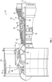
- FIG. 1 schematically illustrates a gas turbine engine 20.
- the gas turbine engine 20 is configured as a two-spool turbofan that has a fan section 22, a compressor section 24, a combustor section 26, and a turbine section 28.
- the illustrative gas turbine engine 20 is merely for example and discussion purposes, and those of skill in the art will appreciate that alternative configurations of gas turbine engines may employ embodiments of the present disclosure.
- the fan section 22 includes a fan 42 that is configured to drive air along a bypass flow path B in a bypass duct defined in a fan case 15.
- the fan 42 is also configured to drive air along a core flow path C for compression and communication into the combustor section 26 then expansion through the turbine section 28.
- FIG. 1 schematically illustrates a gas turbine engine 20.
- the gas turbine engine 20 is configured as a two-spool turbofan that has a fan section 22, a compressor section 24, a combustor section 26, and a turbine section 28.
- the illustrative gas turbine engine 20
- the gas turbine engine 20 includes a low speed spool 30 and a high speed spool 32 mounted for rotation about an engine central longitudinal axis A relative to an engine static structure 36 via one or more bearing systems 38.
- various bearing systems 38 at various locations may be provided, and the location of bearing systems 38 may be varied as appropriate to a particular application and/or engine configuration.
- the low speed spool 30 includes an inner shaft 40 that interconnects the fan 42 of the fan section 22, a first (or low) pressure compressor 44, and a first (or low) pressure turbine 46.
- the inner shaft 40 is connected to the fan 42 through a speed change mechanism, which, in this illustrative gas turbine engine 20, is as a geared architecture 48 to drive the fan 42 at a lower speed than the low speed spool 30.
- the high speed spool 32 includes an outer shaft 50 that interconnects a second (or high) pressure compressor 52 and a second (or high) pressure turbine 54.
- a combustor 56 is arranged in the combustor section 26 between the high pressure compressor 52 and the high pressure turbine 54.
- a mid-turbine frame 57 of the engine static structure 36 is arranged between the high pressure turbine 54 and the low pressure turbine 46.
- the mid-turbine frame 57 may be configured to support one or more of the bearing systems 38 in the turbine section 28.
- the inner shaft 40 and the outer shaft 50 are concentric and rotate via the bearing systems 38 about the engine central longitudinal axis A which is collinear with their longitudinal axes.
- the core airflow through core airflow path C is compressed by the low pressure compressor 44 then the high pressure compressor 52, mixed and burned with fuel in the combustor 56, then expanded over the high pressure turbine 54 and low pressure turbine 46.
- the mid-turbine frame 57 includes airfoils 59 (e.g., vanes) which are arranged in the core airflow path C.
- the turbines 46, 54 rotationally drive the respective low speed spool 30 and high speed spool 32 in response to the expansion of the core airflow. It will be appreciated that each of the positions of the fan section 22, the compressor section 24, the combustor section 26, the turbine section 28, and geared architecture 48 or other fan drive gear system may be varied.
- the geared architecture 48 may be located aft of the combustor section 26 or even aft of the turbine section 28, and the fan section 22 may be positioned forward or aft of the location of the geared architecture 48.
- the gas turbine engine 20 in one example is a high-bypass geared aircraft engine.
- the engine 20 has a bypass ratio that is greater than about six (6), with an example embodiment being greater than about ten (10).
- the geared architecture 48 is an epicyclic gear train, such as a planetary gear system or other gear system, with a gear reduction ratio of greater than about 2.3 and the low pressure turbine 46 has a pressure ratio that is greater than about five (5).
- the bypass ratio of the gas turbine engine 20 is greater than about ten (10:1), a diameter of the fan 42 is significantly larger than that of the low pressure compressor 44, and the low pressure turbine 46 has a pressure ratio that is greater than about five (5:1).
- the low pressure turbine 46 pressure ratio is pressure measured prior to inlet of low pressure turbine 46 as related to the pressure at the outlet of the low pressure turbine 46 prior to an exhaust nozzle.
- the geared architecture 48 may be an epicycle gear train, such as a planetary gear system or other gear system, with a gear reduction ratio of greater than about 2.3:1. It should be understood, however, that the above parameters are only for example and explanatory of one non-limiting embodiment of a geared architecture engine and that the present disclosure is applicable to other gas turbine engines including turbojets or direct drive turbofans, turboshafts, or turboprops.
- the fan section 22 of the gas turbine engine 20 is designed for a particular flight condition -- typically cruise at about 0.8 Mach and about 35,000 feet (10,668 meters).
- 'TSFC' Thrust Specific Fuel Consumption
- Low fan pressure ratio is the pressure ratio across the fan blade alone, without a Fan Exit Guide Vane (“FEGV”) system.
- the low fan pressure ratio as disclosed herein according to one non-limiting embodiment is less than about 1.45.
- Low corrected fan tip speed is the actual fan tip speed in ft/sec divided by an industry standard temperature correction of [(Tram °R) / (518.7 °R)] ⁇ 0.5.
- the "Low corrected fan tip speed” as disclosed herein according to one non-limiting embodiment is less than about 1150 ft / second (350.5 meters/second).
- Gas turbine engines generate substantial amounts of heat that is exhausted from the turbine section 28 into a surrounding atmosphere. This expelled exhaust heat represents wasted energy, and can be a large source of inefficiency in gas turbine engines.
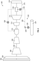
- FIG. 2 a schematic diagram of a turbine engine system 200 in accordance with an embodiment of the present disclosure is shown.
- the turbine engine system 200 may be similar to that shown and described above, but is configured to employ a non-hydrocarbon fuel source, such as liquid/compressed/supercritical hydrogen and/or methane, or other types of cryogenic fuels, as will be appreciated by those of skill in the art.
- the turbine engine system 200 includes an inlet 202, a fan 204, a low pressure compressor 206, a high pressure compressor 208, a combustor 210, a high pressure turbine 212, a low pressure turbine 214, a core nozzle 216, and an outlet 218.
- a core flow path is defined through, at least, the compressor 206,208, the turbine 212, 214, and the combustor sections 210.
- the compressor 206, 208, the turbine 212, 214, and the fan 204 are arranged along a shaft 220.
- the turbine engine system 200 includes a cryogenic fuel system 222.
- the cryogenic fuel system 222 is configured to supply a fuel from a cryogenic fuel tank 224 to the combustor 210.
- the fuel is supplied from the cryogenic fuel tank 224 to the combustor 210 through a fuel supply line 226.
- the fuel supply line 226 may be controlled by a flow controller 228 (e.g., pump(s), valve(s), or the like).
- the flow controller 228 may be configured to control a flow through the fuel supply line 226 based on various criteria as will be appreciated by those of skill in the art.
- various control criteria can include, without limitation, target flow rates, target turbine output, cooling demands at one or more heat exchangers, target flight envelopes, etc.
- the power electronics cooling heat exchanger 230 may receive the cryogenic fuel directly from the cryogenic fuel tank 224 as a first fluid and a power electronics working fluid for power electronics of the turbine engine system 200 (or other aircraft power electronics) as a second fluid.
- a relatively hot power electronics working fluid can pass through the power electronics cooling heat exchanger 230 and heat may be transferred into the cryogenic fuel. This may serve, in some configurations, to begin raising a temperature of the cryogenic fuel to a desired temperature for efficient combustion in the combustor 210.
- the fuel When the fuel is directed along the flow supply line 226, the fuel will pass through a core flow path heat exchanger 232 (e.g., an exhaust waste heat recovery heat exchanger).
- the core flow path heat exchanger 232 is arranged in the core flow path downstream of the combustor 210, and in some embodiments, downstream of the low pressure turbine 214.
- the core flow path heat exchanger 232 is arranged downstream of the low pressure turbine 214 and at or proximate the core nozzle 216 upstream of the outlet 218.
- the fuel will pick up heat from the exhaust of the turbine engine system 200. As such, the temperature of the cryogenic fuel will be increased.
- the heated fuel will then be passed into an expansion turbine 234.
- the expansion turbine 234 the fuel will be expanded.
- the process of passing the fuel through the expansion turbine 234 will cause a phase change from liquid to gas and/or warm the liquid fuel and/or further expand gaseous fuel, which is aided by one or more heat exchangers along the fuel supply line 226.
- the expanded fuel may then pass through an optional supplemental heating heat exchanger 236.
- the supplemental heating heat exchanger 236 is configured to receive the heated (but potentially still relatively cold) fuel as a first fluid and as the second fluid may receive one or more aircraft system fluids, such as, without limitation, engine oil, environmental control system fluids, pneumatic off-takes, or cooled cooling air fluids.
- the fuel will be heated as the other fluid may be cooled.
- the fuel will then be injected into the combustor 210 through one or more fuel injectors, as will be appreciated by those of skill in the art. Because the fuel is heated from the cryogenic state in the cryogenic fuel tank 224 through the various mechanisms along the flow supply line 226, combustion efficiency may be improved.
- the expansion turbine 234 for the cryogenic fuel is arranged along and driven by the shaft 220.
- the shaft 220 may be a two-spool shaft system, such as described with respect to FIG. 1 , having a low spool and a high spool.
- the expansion turbine 234 is configured to be driven by the low spool of the two-spool shaft system.
- the expansion of the cryogenic fuel within the expansion turbine 234 can be used to supplement or augment the cycle of the shaft 220. That is, the expansion within the expansion turbine 234 can provide additional power input to the shaft 220 by mechanically tying the expansion turbine 234 to the shaft 220 (e.g., low spool shaft).
- the shaft 220 may be a shaft of a turbo shaft engine configuration or a shaft of a turbo fan engine configuration, as will be appreciated by those of skill in the art.
- the expansion turbine 234 may be operably coupled to the shaft 220 through a gearbox or other geared system.
- the turboshaft or turboprop engine 300 may be powered by combusting a fuel that is stored at cryogenic temperatures.
- the turboshaft or turboprop engine 300 includes a propeller 302, a compressor section 304, a combustor section 306, a turbine section 308, and an outlet 310.
- the compressor section 304 and the turbine section 308, at least, are arranged along a drive shaft 312.
- the drive shaft 312 is operably connected to a gear system 314 that is configured to drive rotation of the propeller 302.
- the gear system 314 may be a gearbox or the like.
- the turboshaft or turboprop engine 300 includes a cryogenic fuel system 316.
- the cryogenic fuel system 316 is configured to supply a fuel from a cryogenic fuel tank 318 to the combustor section 306.
- the fuel is supplied from the cryogenic fuel tank 318 to the combustor section 306 through a fuel supply line 320.
- the fuel supply line 320 may be controlled by a flow controller 322 (e.g., pump(s), valve(s), or the like).
- the fuel When the fuel is directed along the flow supply line 320, the fuel will pass through a core flow path heat exchanger 324 (e.g., an exhaust waste heat recovery heat exchanger).
- the core flow path heat exchanger 324 is arranged in the core flow path downstream of the combustor 306, and in some embodiments, downstream of the turbine section 308.
- the core flow path heat exchanger 324 is arranged within the outlet 310 of the turboshaft or turboprop engine 300. As the fuel passes through the core flow path heat exchanger 324, the fuel will pick up heat from the exhaust of the turboshaft or turboprop engine 300. As such, the temperature of the cryogenic fuel will be increased.
- the heated fuel will then be passed into an expansion turbine 326. As the fuel passes through the expansion turbine 326 the fuel will be expanded. The process of passing the fuel through the expansion turbine 326 will cause a phase change from liquid to gas and/or warm the liquid fuel and/or further expand gaseous fuel, which is aided by one or more heat exchangers along the fuel supply line 320. The fuel will then be injected into a combustor of the combustor section 306 through one or more fuel injectors, as will be appreciated by those of skill in the art. Because the fuel is heated from the cryogenic state in the cryogenic fuel tank 318 through the various mechanisms along the flow supply line 320, combustion efficiency may be improved.
- the expansion turbine 326 for the cryogenic fuel is arranged along and driven by the shaft 312 of the turboshaft or turboprop engine 300.
- an expansion shaft 328 may be operably coupled to the shaft 312 of the turboshaft or turboprop engine 300.
- the expansion of the cryogenic fuel within the expansion turbine 326 can be used to supplement or augment the cycle of the turboshaft or turboprop engine 300. That is, the expansion within the expansion turbine 326 can provide additional power input to the shaft 312 of the turboshaft or turboprop engine 300 by mechanically tying the expansion turbine 326 to the shaft 312 of the turboshaft or turboprop engine 300.
- a secondary flow controller 330 may be arranged downstream from the expansion turbine 326.
- the secondary flow controller 330 may be configured to control a fuel input into the combustor(s) of the combustor section 306.
- Thrust generated by the turboshaft or turboprop engine 300 can be controlled, for example, through a combination of pitch of the propeller 302, throttling the supply of liquid fuel to the expansion turbine 326 (through control of the flow controller 322), and throttling gaseous fuel to the combustor (through the secondary flow controller 330).
- the supply of fuel to the expansion turbine 326 can enable power to be input to the shaft 312 (e.g., directly or through a gearbox) through work extracted during the expansion process.
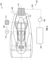
- the turbofan engine 400 may be powered by combusting a fuel that is stored at cryogenic temperatures.
- the turbofan engine 400 includes a fan section, a compressor section, a combustor section, a turbine section, and an outlet, similar to that shown and described above.
- the fan section, the compressor section, and the turbine section at least, are arranged along a drive shaft.
- the turbofan engine 400 includes a cryogenic fuel system 402.
- the cryogenic fuel system 402 is configured to supply a fuel from a cryogenic fuel tank 404 to the combustor section.
- the fuel is supplied from the cryogenic fuel tank 404 to the combustor section through a fuel supply line 406.
- the fuel supply line 406 may be controlled by a flow controller 408 (e.g., pump(s), valve(s), or the like).
- the fuel When the fuel is directed along the flow supply line 406, the fuel will pass through a core flow path heat exchanger 410 (e.g., an exhaust waste heat recovery heat exchanger).
- the core flow path heat exchanger 410 is arranged in the core flow path downstream of the combustor section, and in some embodiments, downstream of the turbine section.
- the core flow path heat exchanger 410 is arranged within the outlet of the turbofan engine 400. As the fuel passes through the core flow path heat exchanger 410, the fuel will pick up heat from the exhaust of the turbofan engine 400. As such, the temperature of the cryogenic fuel will be increased.
- the heated fuel will then be passed into an expansion turbine 412. As the fuel passes through the expansion turbine 412 the fuel will be expanded. The process of passing the fuel through the expansion turbine 412 will cause a phase change from liquid to gas and/or warm the liquid fuel and/or further expand gaseous fuel, which is aided by one or more heat exchangers along the fuel supply line 406.
- the expanded fuel may pass through an optional supplemental heating heat exchanger 414.
- the supplemental heating heat exchanger 414 is configured to receive the heated (but potentially still relatively cold) fuel as a first fluid and as the second fluid may receive one or more aircraft system fluids, such as, without limitation, engine oil, environmental control system fluids, pneumatic off-takes, or cooled cooling air fluids.
- the fuel will be heated as the other fluid may be cooled.
- the fuel will then be injected into a combustor of the combustor section through one or more fuel injectors, as will be appreciated by those of skill in the art. Because the fuel is heated from the cryogenic state in the cryogenic fuel tank 404 through the various mechanisms along the flow supply line 406, combustion efficiency may be improved.
- the expansion turbine 412 for the cryogenic fuel is arranged along and driven by the shaft of the turbofan engine 400.
- the expansion of the cryogenic fuel within the expansion turbine 412 can be used to supplement or augment the cycle of the turbofan engine 400. That is, the expansion within the expansion turbine 412 can provide additional power input to the shaft of the turbofan engine 400 by mechanically tying the expansion turbine 412 to the shaft of the turbofan engine 400 (e.g., low spool shaft).
- a secondary flow controller 416 (e.g., a valve and/or pump) may be arranged downstream from the expansion turbine 412.
- the secondary flow controller 416 may be configured to control a fuel input into the combustor(s) of the combustor section.
- Thrust generated by the turbofan engine 400 can be controlled, for example, through a combination of throttling the supply of liquid fuel to the expansion turbine 412 (through control of the flow controller 408) and throttling gaseous fuel to the combustor (through the secondary flow controller 416).
- the expansion turbine 412 can be configured to add power to the low spool, which in turn can enable a reduction in the amount of fuel burned in the combustor.
- Such configurations can take advantage of energy stored in the cryogenic fuel that is released when the cryogenic fuel is expanded within the expansion turbine 412. Thrust is generally controlled by fan speed, and thus, in such configurations, a control can be implemented to throttle the fuel burned to hold the fan speed.
- one or more optional heat exchangers can provide various cooling to fluids of other engine and/or aircraft systems.
- a heat exchanger can be provided to cryogenically cool power electronics by the fuel, adding some heat to the fuel before recovering heat from another source in the turbine engine (e.g., a source along the core flow path, referred to herein as core flow path heat exchangers).
- a heat exchanger can be provided to cool the engine oil, aircraft ECS needs, pneumatic off-takes, and/or cooled cooling air, downstream of the expansion turbine prior to being injected into the combustor.
- an aircraft ECS cooler heat exchanger could be arrange between the cryogenic power electronics cooler and the core flow path heat exchangers.
- the engine oil cooler or cooled cooling air heat exchangers could alternatively be between the core flow path heat exchangers and expansion turbine.
- the flow controller of the systems may be configured to allow for a portion of the fuel to flow along one or more flow paths.
- two or more separated flows of fuel may be recombined and mixed together prior to or at the point of entering the expansion turbine and/or the combustor.
- a flow controller may be dynamically controlled to ensure a desired temperature of the fuel at the point of injection into the combustor of the turbine engine.
- embodiments of the present disclosure are directed to improved turbine engine systems that employ non-hydrocarbon fuels at cryogenic temperatures.
- the systems described herein may allow the cryogenic fuel to recover heat from various systems such as waste heat-heat exchangers, system component heat exchangers, and expansion turbines.
- expansion turbines may provide supplemental or augmentation to thrust generated by the engines. This may be achieved due to the liquid or cold fuel expanding within the expansion turbine, thus applying force to a shaft of the expansion turbine, which may be mechanically coupled to a shaft of the engine. This additional rotation can be used to generate additional thrust output from the engine.
- the term "about” is intended to include the degree of error associated with measurement of the particular quantity based upon the equipment available at the time of filing the application. For example, “about” may include a range of ⁇ 8%, or 5%, or 2% of a given value or other percentage change as will be appreciated by those of skill in the art for the particular measurement and/or dimensions referred to herein.
Landscapes
- Engineering & Computer Science (AREA)
- Chemical & Material Sciences (AREA)
- Combustion & Propulsion (AREA)
- Mechanical Engineering (AREA)
- General Engineering & Computer Science (AREA)
- Engine Equipment That Uses Special Cycles (AREA)
- Aviation & Aerospace Engineering (AREA)
- Structures Of Non-Positive Displacement Pumps (AREA)
Claims (13)
- Turbinentriebwerksystem (200; 300; 400), umfassend:eine Brennkammer (210; 306), die entlang eines Kernströmungspfads des Turbinentriebwerks angeordnet ist;eine Antriebswelle (220; 312), die mindestens einem Fan (204; 302), einen Verdichterabschnitt (206, 208; 304) und einem daran gekoppelten Turbinenabschnitt (212, 214; 308) aufweist, wobei der Fan dazu konfiguriert ist, durch den rotierend angetriebenen Turbinenabschnitt über die Antriebswelle rotierend angetrieben zu werden, und die Brennkammer entlang des Kernströmungspfads zwischen dem Verdichterabschnitt und dem Turbinenabschnitt angeordnet ist;einen Kryokraftstofftank (224; 318; 404), der dazu konfiguriert ist, der Brennkammer einen Kraftstoff zuzuführen;eine Expansionsturbine (234; 326; 412), die mechanisch an die Antriebswelle gekoppelt und in dem Kernströmungspfad stromabwärts des Turbinenabschnitts angeordnet ist, wobei die Expansionsturbine (234; 326; 412) dazu konfiguriert ist, Kraftstoff aus dem Kryokraftstofftank (224; 318; 404) aufzunehmen und diesen Kraftstoff zu expandieren, wobei die Expansion des Kraftstoffs durch die Expansionsturbine die Rotation der Expansionsturbine antreibt, um eine Leistungseingabe für die Antriebswelle bereitzustellen und die Rotation der Antriebswelle zu ergänzen oder zu verstärken; und eine Strömungszufuhrleitung (226; 320; 406), die den Kryokraftstofftank mit der Brennkammer fluidverbindet, wobei die Expansionsturbine entlang der Strömungszufuhrleitung zwischen dem Kryokraftstofftank und der Brennkammer angeordnet ist.
- Turbinentriebwerksystem nach Anspruch 1, wobei die Antriebswelle (220; 312) eine Niederdruckspule und eine Hochdruckspule umfasst und die Expansionsturbine (234; 326; 412) mechanisch an die Niederdruckspule gekoppelt ist, um die Rotation der Niederdruckspule zu verstärken.
- Turbinentriebwerksystem nach einem der Ansprüche 1 oder 2, wobei der Kraftstoff entweder flüssiger Wasserstoff oder flüssiges Methan ist.
- Turbinentriebwerksystem nach einem der Ansprüche 1, 2 oder 3, wobei die Expansionsturbine (234; 326; 412) dazu konfiguriert ist, während der Expansion des Kraftstoffs Leistung an die Antriebswelle (220; 312) weiterzugeben.
- Turbinentriebwerksystem nach einem der vorhergehenden Ansprüche, ferner umfassend einen Abwärme-Wärmetauscher (232; 324; 410), der stromabwärts der Brennkammer (210; 306) entlang des Kernströmungspfads angeordnet ist, wobei der Abwärme-Wärmetauscher entlang der Strömungszufuhrleitung (226; 320; 406) angeordnet und dazu konfiguriert ist, den Kraftstoff zu erwärmen.
- Turbinentriebwerksystem nach Anspruch 5, wobei der Abwärme-Wärmetauscher entlang der Strömungszufuhrleitung stromaufwärts der Expansionsturbine (234; 326; 412) angeordnet ist.
- Turbinentriebwerksystem nach einem der vorhergehenden Ansprüche, umfassend einen Kühlwärmetauscher (230) für Leistungselektronik, der entlang der Strömungszufuhrleitung (226; 320; 406) zwischen dem Kryokraftstofftank (224; 318; 404) und der Expansionsturbine (234; 326; 412) angeordnet ist.
- Turbinentriebwerksystem nach einem der vorhergehenden Ansprüche, ferner umfassend einen zusätzlichen Kühlwärmetauscher (236; 414), der entlang der Strömungszufuhrleitung (226; 320; 406) angeordnet und dazu konfiguriert ist, mindestens eines von Triebwerksöl, Umweltkontrollsystemfluiden, Pneumatikausspeisungen und gekühlten Kühlluftfluiden zu kühlen.
- Turbinentriebwerksystem nach einem der vorhergehenden Ansprüche, ferner umfassend mindestens eine Strömungssteuerung (228; 322; 408), die entlang der Strömungszufuhrleitung (226; 320; 406) angeordnet und dazu konfiguriert ist, eine Strömung des Kraftstoffs durch die Strömungszufuhrleitung zu steuern.
- Turbinentriebwerksystem nach einem der vorhergehenden Ansprüche, ferner umfassend:
ein Getriebesystem (314), das an die Antriebswelle (220; 312) wirkgekoppelt und dazu konfiguriert ist, die Rotation des Fans anzutreiben. - Luftfahrzeugtriebwerksystem, umfassend:
das Turbinentriebwerksystem (200; 300; 400) nach einem der Ansprüche 1 bis 10. - Luftfahrzeugtriebwerksystem nach Anspruch 11, wobei die Brennkammer (306), die Antriebswelle (312), der Verdichterabschnitt (304) und der Turbinenabschnitt (308) als ein Turbotriebwerk oder ein Turboprop-Triebwerk (300) angeordnet sind.
- Luftfahrzeugtriebwerksystem nach Anspruch 11, wobei die Brennkammer, die Antriebswelle, der Verdichterabschnitt und der Turbinenabschnitt als Turbofan-Triebwerk (400) angeordnet sind.
Applications Claiming Priority (1)
| Application Number | Priority Date | Filing Date | Title |
|---|---|---|---|
| US17/132,080 US11773782B2 (en) | 2020-12-23 | 2020-12-23 | Gas turbine engines having cryogenic fuel systems |
Publications (2)
| Publication Number | Publication Date |
|---|---|
| EP4019752A1 EP4019752A1 (de) | 2022-06-29 |
| EP4019752B1 true EP4019752B1 (de) | 2024-09-18 |
Family
ID=78957448
Family Applications (1)
| Application Number | Title | Priority Date | Filing Date |
|---|---|---|---|
| EP21216172.3A Active EP4019752B1 (de) | 2020-12-23 | 2021-12-20 | Gasturbinentriebwerke mit kryokraftstoffsystemen |
Country Status (2)
| Country | Link |
|---|---|
| US (1) | US11773782B2 (de) |
| EP (1) | EP4019752B1 (de) |
Families Citing this family (16)
| Publication number | Priority date | Publication date | Assignee | Title |
|---|---|---|---|---|
| EP3988845B1 (de) * | 2020-09-30 | 2024-02-14 | Rolls-Royce plc | Direktkraftstoffeinspritzsystem |
| US12055098B2 (en) * | 2021-07-09 | 2024-08-06 | Rtx Corporation | Hydrogen powered engine with exhaust heat exchanger |
| WO2023140891A2 (en) * | 2021-07-09 | 2023-07-27 | Raytheon Technologies Corporation | Turbine engines having hydrogen fuel systems |
| US11761381B2 (en) * | 2021-08-14 | 2023-09-19 | Pratt & Whitney Canada Corp. | Gas turbine engine comprising liquid hydrogen evaporators and heaters |
| US11912416B2 (en) * | 2021-09-09 | 2024-02-27 | Hamilton Sundstrand Corporation | Hydrogen systems for environmental control systems onboard aircraft |
| GB202201313D0 (en) | 2022-02-02 | 2022-03-16 | Rolls Royce Plc | Combination of a gas turbine engine and a power electronics |
| GB202201316D0 (en) * | 2022-02-02 | 2022-03-16 | Rolls Royce Plc | Combination of a gas turbine engine and a power electronics |
| US11987377B2 (en) | 2022-07-08 | 2024-05-21 | Rtx Corporation | Turbo expanders for turbine engines having hydrogen fuel systems |
| US12103699B2 (en) * | 2022-07-08 | 2024-10-01 | Rtx Corporation | Hybrid electric power for turbine engines having hydrogen fuel systems |
| US11905884B1 (en) * | 2022-09-16 | 2024-02-20 | General Electric Company | Hydrogen fuel system for a gas turbine engine |
| US12180893B2 (en) | 2023-01-27 | 2024-12-31 | Rtx Corporation | Hydrogen steam injected turbine engine with turboexpander heat recovery |
| US12435664B2 (en) | 2023-06-16 | 2025-10-07 | Pratt & Whitney Canada Corp. | Gas turbine engine with water recovery system |
| US12486803B2 (en) * | 2023-06-16 | 2025-12-02 | Pratt & Whitney Canada Corp. | Gas turbine engine system with fuel driven turbine |
| EP4501796A1 (de) * | 2023-07-31 | 2025-02-05 | Airbus Operations, S.L.U. | Klimatisierungssystem für ein flugzeug |
| GB202400631D0 (en) * | 2024-01-17 | 2024-02-28 | Rolls Royce Plc | Hydrogen fuelled gas turbine engine |
| US12460580B1 (en) * | 2024-12-13 | 2025-11-04 | Pratt & Whitney Canada Corp. | Heat management system and method for hydrogen-fueled engine |
Family Cites Families (10)
| Publication number | Priority date | Publication date | Assignee | Title |
|---|---|---|---|---|
| US3740949A (en) | 1963-11-20 | 1973-06-26 | Texaco Inc | Fuel cooled ram air reaction propulsion engine |
| US7117663B2 (en) | 2004-05-25 | 2006-10-10 | Jonathan Cleaveland Knapp | Air breathing, hydrogen fueled jet engine for high speed aircraft |
| JP4092728B2 (ja) | 2005-01-25 | 2008-05-28 | 独立行政法人 宇宙航空研究開発機構 | 航空機用推進システム |
| GB0707319D0 (en) * | 2007-04-17 | 2007-05-23 | Rolls Royce Plc | Apparatus and method of operating a gas turbine engine at start-up |
| US8205827B2 (en) | 2008-01-23 | 2012-06-26 | Aurora Flight Sciences Corporation | Hydrazine monopropellant decomposition air turboprop engine |
| CA2804462C (en) * | 2012-07-12 | 2021-05-25 | Pratt & Whitney Canada Corp. | Aircraft power outtake management |
| JP2016504523A (ja) * | 2012-12-28 | 2016-02-12 | ゼネラル・エレクトリック・カンパニイ | 極低温燃料システムを含むタービンエンジンアセンブリ |
| GB2531775B (en) * | 2014-10-30 | 2018-05-09 | Rolls Royce Plc | A gas turbine using cryogenic fuel passed through a fuel turbine |
| US10865713B2 (en) * | 2018-07-20 | 2020-12-15 | Hamilton Sundstrand Corporation | Systems and methods for cooling electronic engine control devices |
| GB2584094B (en) * | 2019-05-20 | 2022-01-26 | Rolls Royce Plc | Engine |
-
2020
- 2020-12-23 US US17/132,080 patent/US11773782B2/en active Active
-
2021
- 2021-12-20 EP EP21216172.3A patent/EP4019752B1/de active Active
Also Published As
| Publication number | Publication date |
|---|---|
| EP4019752A1 (de) | 2022-06-29 |
| US11773782B2 (en) | 2023-10-03 |
| US20220195928A1 (en) | 2022-06-23 |
Similar Documents
| Publication | Publication Date | Title |
|---|---|---|
| EP4019752B1 (de) | Gasturbinentriebwerke mit kryokraftstoffsystemen | |
| EP3904658B1 (de) | Gasturbinenmotoren mit kryogenen kraftstoffsystemen | |
| US12577914B2 (en) | Methods and systems for starting hydrogen powered gas generators | |
| EP4227513B1 (de) | Turbinenmotor mit massenabweisung | |
| EP4227509A1 (de) | Kryogenisch unterstützte abgaskondensation | |
| EP4089271A1 (de) | Turbinentriebwerke mit wasserstofftreibstoffsystemen | |
| EP3885550B1 (de) | Überkritischer co2-zyklus für gasturbinentriebwerke mit zusätzlicher kühlung | |
| US20230010158A1 (en) | Hydrogen powered geared turbofan engine with reduced size core engine | |
| EP4137686B1 (de) | Antriebssysteme für flugzeuge | |
| US12103699B2 (en) | Hybrid electric power for turbine engines having hydrogen fuel systems | |
| US20250198330A1 (en) | Hydrogen turbine power assisted condensation | |
| US12044176B2 (en) | Turbine engines having hydrogen fuel systems | |
| EP4303416A1 (de) | Turboexpander für turbinenmotoren mit wasserstoffbrennstoffsystemen | |
| EP4303417A1 (de) | Hybrider elektrischer wasserstoffmotor für flugzeuge | |
| EP3792473A1 (de) | Brennstoffgekühlte kühlluft | |
| US20250290635A1 (en) | Liquid hydrogen fuel system with thermal compression |
Legal Events
| Date | Code | Title | Description |
|---|---|---|---|
| PUAI | Public reference made under article 153(3) epc to a published international application that has entered the european phase |
Free format text: ORIGINAL CODE: 0009012 |
|
| STAA | Information on the status of an ep patent application or granted ep patent |
Free format text: STATUS: THE APPLICATION HAS BEEN PUBLISHED |
|
| AK | Designated contracting states |
Kind code of ref document: A1 Designated state(s): AL AT BE BG CH CY CZ DE DK EE ES FI FR GB GR HR HU IE IS IT LI LT LU LV MC MK MT NL NO PL PT RO RS SE SI SK SM TR |
|
| STAA | Information on the status of an ep patent application or granted ep patent |
Free format text: STATUS: REQUEST FOR EXAMINATION WAS MADE |
|
| 17P | Request for examination filed |
Effective date: 20221229 |
|
| RBV | Designated contracting states (corrected) |
Designated state(s): AL AT BE BG CH CY CZ DE DK EE ES FI FR GB GR HR HU IE IS IT LI LT LU LV MC MK MT NL NO PL PT RO RS SE SI SK SM TR |
|
| RAP3 | Party data changed (applicant data changed or rights of an application transferred) |
Owner name: RTX CORPORATION |
|
| GRAP | Despatch of communication of intention to grant a patent |
Free format text: ORIGINAL CODE: EPIDOSNIGR1 |
|
| STAA | Information on the status of an ep patent application or granted ep patent |
Free format text: STATUS: GRANT OF PATENT IS INTENDED |
|
| INTG | Intention to grant announced |
Effective date: 20240409 |
|
| GRAS | Grant fee paid |
Free format text: ORIGINAL CODE: EPIDOSNIGR3 |
|
| GRAA | (expected) grant |
Free format text: ORIGINAL CODE: 0009210 |
|
| STAA | Information on the status of an ep patent application or granted ep patent |
Free format text: STATUS: THE PATENT HAS BEEN GRANTED |
|
| AK | Designated contracting states |
Kind code of ref document: B1 Designated state(s): AL AT BE BG CH CY CZ DE DK EE ES FI FR GB GR HR HU IE IS IT LI LT LU LV MC MK MT NL NO PL PT RO RS SE SI SK SM TR |
|
| REG | Reference to a national code |
Ref country code: GB Ref legal event code: FG4D |
|
| REG | Reference to a national code |
Ref country code: CH Ref legal event code: EP |
|
| REG | Reference to a national code |
Ref country code: IE Ref legal event code: FG4D |
|
| REG | Reference to a national code |
Ref country code: DE Ref legal event code: R096 Ref document number: 602021018931 Country of ref document: DE |
|
| REG | Reference to a national code |
Ref country code: LT Ref legal event code: MG9D |
|
| PG25 | Lapsed in a contracting state [announced via postgrant information from national office to epo] |
Ref country code: NO Free format text: LAPSE BECAUSE OF FAILURE TO SUBMIT A TRANSLATION OF THE DESCRIPTION OR TO PAY THE FEE WITHIN THE PRESCRIBED TIME-LIMIT Effective date: 20241218 |
|
| PG25 | Lapsed in a contracting state [announced via postgrant information from national office to epo] |
Ref country code: GR Free format text: LAPSE BECAUSE OF FAILURE TO SUBMIT A TRANSLATION OF THE DESCRIPTION OR TO PAY THE FEE WITHIN THE PRESCRIBED TIME-LIMIT Effective date: 20241219 Ref country code: FI Free format text: LAPSE BECAUSE OF FAILURE TO SUBMIT A TRANSLATION OF THE DESCRIPTION OR TO PAY THE FEE WITHIN THE PRESCRIBED TIME-LIMIT Effective date: 20240918 |
|
| PG25 | Lapsed in a contracting state [announced via postgrant information from national office to epo] |
Ref country code: BG Free format text: LAPSE BECAUSE OF FAILURE TO SUBMIT A TRANSLATION OF THE DESCRIPTION OR TO PAY THE FEE WITHIN THE PRESCRIBED TIME-LIMIT Effective date: 20240918 |
|
| PG25 | Lapsed in a contracting state [announced via postgrant information from national office to epo] |
Ref country code: LV Free format text: LAPSE BECAUSE OF FAILURE TO SUBMIT A TRANSLATION OF THE DESCRIPTION OR TO PAY THE FEE WITHIN THE PRESCRIBED TIME-LIMIT Effective date: 20240918 |
|
| PG25 | Lapsed in a contracting state [announced via postgrant information from national office to epo] |
Ref country code: HR Free format text: LAPSE BECAUSE OF FAILURE TO SUBMIT A TRANSLATION OF THE DESCRIPTION OR TO PAY THE FEE WITHIN THE PRESCRIBED TIME-LIMIT Effective date: 20240918 |
|
| REG | Reference to a national code |
Ref country code: NL Ref legal event code: MP Effective date: 20240918 |
|
| PG25 | Lapsed in a contracting state [announced via postgrant information from national office to epo] |
Ref country code: RS Free format text: LAPSE BECAUSE OF FAILURE TO SUBMIT A TRANSLATION OF THE DESCRIPTION OR TO PAY THE FEE WITHIN THE PRESCRIBED TIME-LIMIT Effective date: 20241218 |
|
| PG25 | Lapsed in a contracting state [announced via postgrant information from national office to epo] |
Ref country code: RS Free format text: LAPSE BECAUSE OF FAILURE TO SUBMIT A TRANSLATION OF THE DESCRIPTION OR TO PAY THE FEE WITHIN THE PRESCRIBED TIME-LIMIT Effective date: 20241218 Ref country code: NO Free format text: LAPSE BECAUSE OF FAILURE TO SUBMIT A TRANSLATION OF THE DESCRIPTION OR TO PAY THE FEE WITHIN THE PRESCRIBED TIME-LIMIT Effective date: 20241218 Ref country code: LV Free format text: LAPSE BECAUSE OF FAILURE TO SUBMIT A TRANSLATION OF THE DESCRIPTION OR TO PAY THE FEE WITHIN THE PRESCRIBED TIME-LIMIT Effective date: 20240918 Ref country code: HR Free format text: LAPSE BECAUSE OF FAILURE TO SUBMIT A TRANSLATION OF THE DESCRIPTION OR TO PAY THE FEE WITHIN THE PRESCRIBED TIME-LIMIT Effective date: 20240918 Ref country code: GR Free format text: LAPSE BECAUSE OF FAILURE TO SUBMIT A TRANSLATION OF THE DESCRIPTION OR TO PAY THE FEE WITHIN THE PRESCRIBED TIME-LIMIT Effective date: 20241219 Ref country code: FI Free format text: LAPSE BECAUSE OF FAILURE TO SUBMIT A TRANSLATION OF THE DESCRIPTION OR TO PAY THE FEE WITHIN THE PRESCRIBED TIME-LIMIT Effective date: 20240918 Ref country code: BG Free format text: LAPSE BECAUSE OF FAILURE TO SUBMIT A TRANSLATION OF THE DESCRIPTION OR TO PAY THE FEE WITHIN THE PRESCRIBED TIME-LIMIT Effective date: 20240918 |
|
| REG | Reference to a national code |
Ref country code: AT Ref legal event code: MK05 Ref document number: 1724861 Country of ref document: AT Kind code of ref document: T Effective date: 20240918 |
|
| PG25 | Lapsed in a contracting state [announced via postgrant information from national office to epo] |
Ref country code: NL Free format text: LAPSE BECAUSE OF FAILURE TO SUBMIT A TRANSLATION OF THE DESCRIPTION OR TO PAY THE FEE WITHIN THE PRESCRIBED TIME-LIMIT Effective date: 20240918 |
|
| PG25 | Lapsed in a contracting state [announced via postgrant information from national office to epo] |
Ref country code: PT Free format text: LAPSE BECAUSE OF FAILURE TO SUBMIT A TRANSLATION OF THE DESCRIPTION OR TO PAY THE FEE WITHIN THE PRESCRIBED TIME-LIMIT Effective date: 20250120 Ref country code: IS Free format text: LAPSE BECAUSE OF FAILURE TO SUBMIT A TRANSLATION OF THE DESCRIPTION OR TO PAY THE FEE WITHIN THE PRESCRIBED TIME-LIMIT Effective date: 20250118 |
|
| PG25 | Lapsed in a contracting state [announced via postgrant information from national office to epo] |
Ref country code: RO Free format text: LAPSE BECAUSE OF FAILURE TO SUBMIT A TRANSLATION OF THE DESCRIPTION OR TO PAY THE FEE WITHIN THE PRESCRIBED TIME-LIMIT Effective date: 20240918 Ref country code: SM Free format text: LAPSE BECAUSE OF FAILURE TO SUBMIT A TRANSLATION OF THE DESCRIPTION OR TO PAY THE FEE WITHIN THE PRESCRIBED TIME-LIMIT Effective date: 20240918 |
|
| PG25 | Lapsed in a contracting state [announced via postgrant information from national office to epo] |
Ref country code: ES Free format text: LAPSE BECAUSE OF FAILURE TO SUBMIT A TRANSLATION OF THE DESCRIPTION OR TO PAY THE FEE WITHIN THE PRESCRIBED TIME-LIMIT Effective date: 20240918 |
|
| PG25 | Lapsed in a contracting state [announced via postgrant information from national office to epo] |
Ref country code: EE Free format text: LAPSE BECAUSE OF FAILURE TO SUBMIT A TRANSLATION OF THE DESCRIPTION OR TO PAY THE FEE WITHIN THE PRESCRIBED TIME-LIMIT Effective date: 20240918 Ref country code: AT Free format text: LAPSE BECAUSE OF FAILURE TO SUBMIT A TRANSLATION OF THE DESCRIPTION OR TO PAY THE FEE WITHIN THE PRESCRIBED TIME-LIMIT Effective date: 20240918 |
|
| PG25 | Lapsed in a contracting state [announced via postgrant information from national office to epo] |
Ref country code: PL Free format text: LAPSE BECAUSE OF FAILURE TO SUBMIT A TRANSLATION OF THE DESCRIPTION OR TO PAY THE FEE WITHIN THE PRESCRIBED TIME-LIMIT Effective date: 20240918 Ref country code: CZ Free format text: LAPSE BECAUSE OF FAILURE TO SUBMIT A TRANSLATION OF THE DESCRIPTION OR TO PAY THE FEE WITHIN THE PRESCRIBED TIME-LIMIT Effective date: 20240918 |
|
| PG25 | Lapsed in a contracting state [announced via postgrant information from national office to epo] |
Ref country code: IT Free format text: LAPSE BECAUSE OF FAILURE TO SUBMIT A TRANSLATION OF THE DESCRIPTION OR TO PAY THE FEE WITHIN THE PRESCRIBED TIME-LIMIT Effective date: 20240918 Ref country code: SK Free format text: LAPSE BECAUSE OF FAILURE TO SUBMIT A TRANSLATION OF THE DESCRIPTION OR TO PAY THE FEE WITHIN THE PRESCRIBED TIME-LIMIT Effective date: 20240918 |
|
| REG | Reference to a national code |
Ref country code: DE Ref legal event code: R097 Ref document number: 602021018931 Country of ref document: DE |
|
| PG25 | Lapsed in a contracting state [announced via postgrant information from national office to epo] |
Ref country code: MC Free format text: LAPSE BECAUSE OF FAILURE TO SUBMIT A TRANSLATION OF THE DESCRIPTION OR TO PAY THE FEE WITHIN THE PRESCRIBED TIME-LIMIT Effective date: 20240918 |
|
| PG25 | Lapsed in a contracting state [announced via postgrant information from national office to epo] |
Ref country code: DK Free format text: LAPSE BECAUSE OF FAILURE TO SUBMIT A TRANSLATION OF THE DESCRIPTION OR TO PAY THE FEE WITHIN THE PRESCRIBED TIME-LIMIT Effective date: 20240918 |
|
| PLBE | No opposition filed within time limit |
Free format text: ORIGINAL CODE: 0009261 |
|
| STAA | Information on the status of an ep patent application or granted ep patent |
Free format text: STATUS: NO OPPOSITION FILED WITHIN TIME LIMIT |
|
| REG | Reference to a national code |
Ref country code: CH Ref legal event code: PL |
|
| PG25 | Lapsed in a contracting state [announced via postgrant information from national office to epo] |
Ref country code: LU Free format text: LAPSE BECAUSE OF NON-PAYMENT OF DUE FEES Effective date: 20241220 |
|
| 26N | No opposition filed |
Effective date: 20250619 |
|
| PG25 | Lapsed in a contracting state [announced via postgrant information from national office to epo] |
Ref country code: SE Free format text: LAPSE BECAUSE OF FAILURE TO SUBMIT A TRANSLATION OF THE DESCRIPTION OR TO PAY THE FEE WITHIN THE PRESCRIBED TIME-LIMIT Effective date: 20240918 |
|
| REG | Reference to a national code |
Ref country code: BE Ref legal event code: MM Effective date: 20241231 |
|
| PG25 | Lapsed in a contracting state [announced via postgrant information from national office to epo] |
Ref country code: BE Free format text: LAPSE BECAUSE OF NON-PAYMENT OF DUE FEES Effective date: 20241231 |
|
| PG25 | Lapsed in a contracting state [announced via postgrant information from national office to epo] |
Ref country code: CH Free format text: LAPSE BECAUSE OF NON-PAYMENT OF DUE FEES Effective date: 20241231 |
|
| PG25 | Lapsed in a contracting state [announced via postgrant information from national office to epo] |
Ref country code: IE Free format text: LAPSE BECAUSE OF NON-PAYMENT OF DUE FEES Effective date: 20241220 |
|
| PGFP | Annual fee paid to national office [announced via postgrant information from national office to epo] |
Ref country code: DE Payment date: 20251126 Year of fee payment: 5 |
|
| PGFP | Annual fee paid to national office [announced via postgrant information from national office to epo] |
Ref country code: GB Payment date: 20251119 Year of fee payment: 5 |
|
| PGFP | Annual fee paid to national office [announced via postgrant information from national office to epo] |
Ref country code: FR Payment date: 20251120 Year of fee payment: 5 |