EP4137686B1 - Antriebssysteme für flugzeuge - Google Patents
Antriebssysteme für flugzeuge Download PDFInfo
- Publication number
- EP4137686B1 EP4137686B1 EP22190642.3A EP22190642A EP4137686B1 EP 4137686 B1 EP4137686 B1 EP 4137686B1 EP 22190642 A EP22190642 A EP 22190642A EP 4137686 B1 EP4137686 B1 EP 4137686B1
- Authority
- EP
- European Patent Office
- Prior art keywords
- heat exchanger
- flow path
- fuel
- shaft
- turbine
- Prior art date
- Legal status (The legal status is an assumption and is not a legal conclusion. Google has not performed a legal analysis and makes no representation as to the accuracy of the status listed.)
- Active
Links
Images

Classifications
-
- F—MECHANICAL ENGINEERING; LIGHTING; HEATING; WEAPONS; BLASTING
- F02—COMBUSTION ENGINES; HOT-GAS OR COMBUSTION-PRODUCT ENGINE PLANTS
- F02K—JET-PROPULSION PLANTS
- F02K3/00—Plants including a gas turbine driving a compressor or a ducted fan
- F02K3/08—Plants including a gas turbine driving a compressor or a ducted fan with supplementary heating of the working fluid; Control thereof
- F02K3/105—Heating the by-pass flow
- F02K3/115—Heating the by-pass flow by means of indirect heat exchange
-
- F—MECHANICAL ENGINEERING; LIGHTING; HEATING; WEAPONS; BLASTING
- F02—COMBUSTION ENGINES; HOT-GAS OR COMBUSTION-PRODUCT ENGINE PLANTS
- F02C—GAS-TURBINE PLANTS; AIR INTAKES FOR JET-PROPULSION PLANTS; CONTROLLING FUEL SUPPLY IN AIR-BREATHING JET-PROPULSION PLANTS
- F02C1/00—Gas-turbine plants characterised by the use of hot gases or unheated pressurised gases, as the working fluid
- F02C1/04—Gas-turbine plants characterised by the use of hot gases or unheated pressurised gases, as the working fluid the working fluid being heated indirectly
- F02C1/10—Closed cycles
-
- F—MECHANICAL ENGINEERING; LIGHTING; HEATING; WEAPONS; BLASTING
- F02—COMBUSTION ENGINES; HOT-GAS OR COMBUSTION-PRODUCT ENGINE PLANTS
- F02C—GAS-TURBINE PLANTS; AIR INTAKES FOR JET-PROPULSION PLANTS; CONTROLLING FUEL SUPPLY IN AIR-BREATHING JET-PROPULSION PLANTS
- F02C1/00—Gas-turbine plants characterised by the use of hot gases or unheated pressurised gases, as the working fluid
- F02C1/04—Gas-turbine plants characterised by the use of hot gases or unheated pressurised gases, as the working fluid the working fluid being heated indirectly
-
- F—MECHANICAL ENGINEERING; LIGHTING; HEATING; WEAPONS; BLASTING
- F02—COMBUSTION ENGINES; HOT-GAS OR COMBUSTION-PRODUCT ENGINE PLANTS
- F02C—GAS-TURBINE PLANTS; AIR INTAKES FOR JET-PROPULSION PLANTS; CONTROLLING FUEL SUPPLY IN AIR-BREATHING JET-PROPULSION PLANTS
- F02C3/00—Gas-turbine plants characterised by the use of combustion products as the working fluid
- F02C3/20—Gas-turbine plants characterised by the use of combustion products as the working fluid using a special fuel, oxidant, or dilution fluid to generate the combustion products
- F02C3/22—Gas-turbine plants characterised by the use of combustion products as the working fluid using a special fuel, oxidant, or dilution fluid to generate the combustion products the fuel or oxidant being gaseous at standard temperature and pressure
-
- F—MECHANICAL ENGINEERING; LIGHTING; HEATING; WEAPONS; BLASTING
- F02—COMBUSTION ENGINES; HOT-GAS OR COMBUSTION-PRODUCT ENGINE PLANTS
- F02C—GAS-TURBINE PLANTS; AIR INTAKES FOR JET-PROPULSION PLANTS; CONTROLLING FUEL SUPPLY IN AIR-BREATHING JET-PROPULSION PLANTS
- F02C6/00—Plural gas-turbine plants; Combinations of gas-turbine plants with other apparatus; Adaptations of gas-turbine plants for special use
- F02C6/20—Adaptations of gas-turbine plants for driving vehicles
- F02C6/206—Adaptations of gas-turbine plants for driving vehicles the vehicles being airscrew driven
-
- F—MECHANICAL ENGINEERING; LIGHTING; HEATING; WEAPONS; BLASTING
- F02—COMBUSTION ENGINES; HOT-GAS OR COMBUSTION-PRODUCT ENGINE PLANTS
- F02C—GAS-TURBINE PLANTS; AIR INTAKES FOR JET-PROPULSION PLANTS; CONTROLLING FUEL SUPPLY IN AIR-BREATHING JET-PROPULSION PLANTS
- F02C7/00—Features, components parts, details or accessories, not provided for in, or of interest apart form groups F02C1/00 - F02C6/00; Air intakes for jet-propulsion plants
- F02C7/08—Heating air supply before combustion, e.g. by exhaust gases
- F02C7/10—Heating air supply before combustion, e.g. by exhaust gases by means of regenerative heat-exchangers
-
- F—MECHANICAL ENGINEERING; LIGHTING; HEATING; WEAPONS; BLASTING
- F02—COMBUSTION ENGINES; HOT-GAS OR COMBUSTION-PRODUCT ENGINE PLANTS
- F02C—GAS-TURBINE PLANTS; AIR INTAKES FOR JET-PROPULSION PLANTS; CONTROLLING FUEL SUPPLY IN AIR-BREATHING JET-PROPULSION PLANTS
- F02C7/00—Features, components parts, details or accessories, not provided for in, or of interest apart form groups F02C1/00 - F02C6/00; Air intakes for jet-propulsion plants
- F02C7/22—Fuel supply systems
- F02C7/224—Heating fuel before feeding to the burner
-
- F—MECHANICAL ENGINEERING; LIGHTING; HEATING; WEAPONS; BLASTING
- F02—COMBUSTION ENGINES; HOT-GAS OR COMBUSTION-PRODUCT ENGINE PLANTS
- F02C—GAS-TURBINE PLANTS; AIR INTAKES FOR JET-PROPULSION PLANTS; CONTROLLING FUEL SUPPLY IN AIR-BREATHING JET-PROPULSION PLANTS
- F02C7/00—Features, components parts, details or accessories, not provided for in, or of interest apart form groups F02C1/00 - F02C6/00; Air intakes for jet-propulsion plants
- F02C7/36—Power transmission arrangements between the different shafts of the gas turbine plant, or between the gas-turbine plant and the power user
-
- F—MECHANICAL ENGINEERING; LIGHTING; HEATING; WEAPONS; BLASTING
- F02—COMBUSTION ENGINES; HOT-GAS OR COMBUSTION-PRODUCT ENGINE PLANTS
- F02K—JET-PROPULSION PLANTS
- F02K3/00—Plants including a gas turbine driving a compressor or a ducted fan
- F02K3/02—Plants including a gas turbine driving a compressor or a ducted fan in which part of the working fluid by-passes the turbine and combustion chamber
- F02K3/04—Plants including a gas turbine driving a compressor or a ducted fan in which part of the working fluid by-passes the turbine and combustion chamber the plant including ducted fans, i.e. fans with high volume, low pressure outputs, for augmenting the jet thrust, e.g. of double-flow type
- F02K3/06—Plants including a gas turbine driving a compressor or a ducted fan in which part of the working fluid by-passes the turbine and combustion chamber the plant including ducted fans, i.e. fans with high volume, low pressure outputs, for augmenting the jet thrust, e.g. of double-flow type with front fan
-
- F—MECHANICAL ENGINEERING; LIGHTING; HEATING; WEAPONS; BLASTING
- F05—INDEXING SCHEMES RELATING TO ENGINES OR PUMPS IN VARIOUS SUBCLASSES OF CLASSES F01-F04
- F05D—INDEXING SCHEME FOR ASPECTS RELATING TO NON-POSITIVE-DISPLACEMENT MACHINES OR ENGINES, GAS-TURBINES OR JET-PROPULSION PLANTS
- F05D2220/00—Application
- F05D2220/30—Application in turbines
- F05D2220/32—Application in turbines in gas turbines
- F05D2220/323—Application in turbines in gas turbines for aircraft propulsion, e.g. jet engines
-
- F—MECHANICAL ENGINEERING; LIGHTING; HEATING; WEAPONS; BLASTING
- F05—INDEXING SCHEMES RELATING TO ENGINES OR PUMPS IN VARIOUS SUBCLASSES OF CLASSES F01-F04
- F05D—INDEXING SCHEME FOR ASPECTS RELATING TO NON-POSITIVE-DISPLACEMENT MACHINES OR ENGINES, GAS-TURBINES OR JET-PROPULSION PLANTS
- F05D2240/00—Components
- F05D2240/35—Combustors or associated equipment
-
- F—MECHANICAL ENGINEERING; LIGHTING; HEATING; WEAPONS; BLASTING
- F05—INDEXING SCHEMES RELATING TO ENGINES OR PUMPS IN VARIOUS SUBCLASSES OF CLASSES F01-F04
- F05D—INDEXING SCHEME FOR ASPECTS RELATING TO NON-POSITIVE-DISPLACEMENT MACHINES OR ENGINES, GAS-TURBINES OR JET-PROPULSION PLANTS
- F05D2260/00—Function
- F05D2260/20—Heat transfer, e.g. cooling
- F05D2260/213—Heat transfer, e.g. cooling by the provision of a heat exchanger within the cooling circuit
-
- F—MECHANICAL ENGINEERING; LIGHTING; HEATING; WEAPONS; BLASTING
- F05—INDEXING SCHEMES RELATING TO ENGINES OR PUMPS IN VARIOUS SUBCLASSES OF CLASSES F01-F04
- F05D—INDEXING SCHEME FOR ASPECTS RELATING TO NON-POSITIVE-DISPLACEMENT MACHINES OR ENGINES, GAS-TURBINES OR JET-PROPULSION PLANTS
- F05D2260/00—Function
- F05D2260/20—Heat transfer, e.g. cooling
- F05D2260/232—Heat transfer, e.g. cooling characterized by the cooling medium
-
- F—MECHANICAL ENGINEERING; LIGHTING; HEATING; WEAPONS; BLASTING
- F05—INDEXING SCHEMES RELATING TO ENGINES OR PUMPS IN VARIOUS SUBCLASSES OF CLASSES F01-F04
- F05D—INDEXING SCHEME FOR ASPECTS RELATING TO NON-POSITIVE-DISPLACEMENT MACHINES OR ENGINES, GAS-TURBINES OR JET-PROPULSION PLANTS
- F05D2260/00—Function
- F05D2260/60—Fluid transfer
- F05D2260/606—Bypassing the fluid
-
- Y—GENERAL TAGGING OF NEW TECHNOLOGICAL DEVELOPMENTS; GENERAL TAGGING OF CROSS-SECTIONAL TECHNOLOGIES SPANNING OVER SEVERAL SECTIONS OF THE IPC; TECHNICAL SUBJECTS COVERED BY FORMER USPC CROSS-REFERENCE ART COLLECTIONS [XRACs] AND DIGESTS
- Y02—TECHNOLOGIES OR APPLICATIONS FOR MITIGATION OR ADAPTATION AGAINST CLIMATE CHANGE
- Y02T—CLIMATE CHANGE MITIGATION TECHNOLOGIES RELATED TO TRANSPORTATION
- Y02T50/00—Aeronautics or air transport
- Y02T50/60—Efficient propulsion technologies, e.g. for aircraft
Definitions
- the present disclosure relates generally to aircraft propulsion systems.
- Gas turbine engines such as those utilized in commercial and military aircraft, include a compressor section that compresses air, a combustor section in which the compressed air is mixed with a fuel and ignited, and a turbine section across which the resultant combustion products are expanded.
- the expansion of the combustion products drives the turbine section to rotate.
- the turbine section is connected to the compressor section via a shaft, the rotation of the turbine section further drives the compressor section to rotate.
- a fan is also connected to the shaft and is driven to rotate via rotation of the turbine.
- US 2017/356340 1 A prior art aircraft propulsion system having the features of the preamble of claim 1 is disclosed in US 2017/356340 1 .
- US 2017/58834 A1 discloses another prior art aircraft propulsion system.
- an aircraft propulsion system is provided in accordance with claim 1.
- further embodiments of the aircraft propulsion systems may include that the supercritical fluid is CO 2 that is passed through the turbine, the cooler heat exchanger, the compressor, and the recovery heat exchanger.
- further embodiments of the aircraft propulsion systems may include a gear system coupled to the shaft between the turbine and the fan.
- further embodiments of the aircraft propulsion systems may include that the closed loop-supercritical fluid system further comprises a recuperator heat exchanger arranged between the turbine and the cooler heat exchanger along the closed-loop flow path.
- recuperator heat exchanger is a supercritical fluid-to-supercritical fluid heat exchanger.
- further embodiments of the aircraft propulsion systems may include a cryogenic fuel tank configured to supply fuel to the burner through a fuel flow path, wherein the cooler heat exchanger is a fuel-to-supercritical fluid heat exchanger.
- further embodiments of the aircraft propulsion systems may include a turbo expander operably coupled to the shaft and arranged between the cryogenic fuel tank and the burner.
- cooler heat exchanger is an air-to-supercritical fluid heat exchanger.
- further embodiments of the aircraft propulsion systems may include that the cooler heat exchanger is arranged within a bypass duct downstream of the fan.
- further embodiments of the aircraft propulsion systems may include a bypass flow path defining a flow path of air that passes through an air inlet, through the fan coupled to a shaft, through a bypass duct, and out a bypass nozzle, a hot gas flow path defining a flow path of air that passes through the air inlet, through the fan, into the burner for combustion with fuel to generate combusted gas, and through the recovery heat exchanger, and out the exhaust nozzle, and a closed-loop flow path defining a closed-loop flow path of a supercritical fluid that passes through the turbine operably coupled to the shaft to drive rotation of the shaft, the cooler heat exchanger, the compressor coupled to the shaft, into the recovery heat exchanger, and back to the turbine.
- the turbine of the closed-loop flow path drives rotation of the shaft, the compressor, and the fan.
- further embodiments of the aircraft propulsion systems may include a fuel flow path defining a flow path from a fuel tank to the burner of the hot gas flow path.
- further embodiments of the aircraft propulsion systems may include a turbo expander coupled to the shaft and configured to expand a fuel prior to injection into the burner.
- further embodiments of the aircraft propulsion systems may include a first gear system coupled to the shaft between the turbine and the turbo expander and a second gear system coupled to the shaft between the turbo expander and the fan.
- further embodiments of the aircraft propulsion systems may include that a fuel in the fuel flow path is cryogenic fuel.
- further embodiments of the aircraft propulsion systems may include that the cryogenic fuel is hydrogen.
- further embodiments of the aircraft propulsion systems may include that the cooler heat exchanger of the closed-loop flow path receives fuel to form a fuel-to-supercritical fluid heat exchanger.
- further embodiments of the aircraft propulsion systems may include a gear system coupled to the shaft between the turbine and the fan.
- further embodiments of the aircraft propulsion systems may include that the hot gas flow path further comprises a blower arranged between the fan and the burner to increase a speed of the air passing through the hot gas flow path.
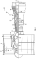
- FIG. 1 schematically illustrates a gas turbine engine 20.
- the gas turbine engine 20 is configured as a two-spool turbofan that has a fan section 22, a compressor section 24, a combustor section 26, and a turbine section 28.
- the illustrative gas turbine engine 20 is merely for example and discussion purposes, and those of skill in the art will appreciate that alternative configurations of gas turbine engines may employ embodiments of the present disclosure.
- the fan section 22 includes a fan 42 that is configured to drive air along a bypass flow path B in a bypass duct defined within a nacelle 15.
- the fan 42 is also configured to drive air along a core flow path C for compression and communication into the combustor section 26 then expansion through the turbine section 28.
- FIG. 1 schematically illustrates a gas turbine engine 20.
- the gas turbine engine 20 is configured as a two-spool turbofan that has a fan section 22, a compressor section 24, a combustor section 26, and a turbine section 28.
- the gas turbine engine 20 includes a low speed spool 30 and a high speed spool 32 mounted for rotation about an engine central longitudinal axis A relative to an engine static structure 36 via one or more bearing systems 38.
- various bearing systems 38 at various locations may be provided, and the location of bearing systems 38 may be varied as appropriate to a particular application and/or engine configuration.
- the low speed spool 30 includes an inner shaft 40 that interconnects the fan 42 of the fan section 22, a first (or low) pressure compressor 44, and a first (or low) pressure turbine 46.
- the inner shaft 40 is connected to the fan 42 through a speed change mechanism, which, in this illustrative gas turbine engine 20, is as a geared architecture 48 to drive the fan 42 at a lower speed than the low speed spool 30.
- the high speed spool 32 includes an outer shaft 50 that interconnects a second (or high) pressure compressor 52 and a second (or high) pressure turbine 54.
- a combustor 56 is arranged in the combustor section 26 between the high pressure compressor 52 and the high pressure turbine 54.
- a mid-turbine frame 57 of the engine static structure 36 is arranged between the high pressure turbine 54 and the low pressure turbine 46.
- the mid-turbine frame 57 may be configured to support one or more of the bearing systems 38 in the turbine section 28.
- the inner shaft 40 and the outer shaft 50 are concentric and rotate via the bearing systems 38 about the engine central longitudinal axis A which is collinear with their longitudinal axes.
- the core airflow through core airflow path C is compressed by the low pressure compressor 44 then the high pressure compressor 52, mixed and burned with fuel in the combustor 56, then expanded over the high pressure turbine 54 and low pressure turbine 46.
- the mid-turbine frame 57 includes airfoils 59 (e.g., vanes) which are arranged in the core airflow path C.
- the turbines 46, 54 rotationally drive the respective low speed spool 30 and high speed spool 32 in response to the expansion of the core airflow. It will be appreciated that each of the positions of the fan section 22, the compressor section 24, the combustor section 26, the turbine section 28, and geared architecture 48 or other fan drive gear system may be varied.
- the geared architecture 48 may be located aft of the combustor section 26 or even aft of the turbine section 28, and the fan section 22 may be positioned forward or aft of the location of the geared architecture 48.
- the gas turbine engine 20 in one example is a high-bypass geared aircraft engine.
- the gas turbine engine 20 has a bypass ratio that is greater than about six, with an example embodiment being greater than about ten.
- the geared architecture 48 is an epicyclic gear train, such as a planetary gear system or other gear system, with a gear reduction ratio of greater than about 2.3 and the low pressure turbine 46 has a pressure ratio that is greater than about five.
- the bypass ratio of the gas turbine engine 20 is greater than about ten, a diameter of the fan 42 is significantly larger than that of the low pressure compressor 44, and the low pressure turbine 46 has a pressure ratio that is greater than about five.
- the low pressure turbine 46 pressure ratio is pressure measured prior to inlet of low pressure turbine 46 as related to the pressure at the outlet of the low pressure turbine 46 prior to an exhaust nozzle.
- the geared architecture 48 may be an epicycle gear train, such as a planetary gear system or other gear system, with a gear reduction ratio of greater than about 2.3:1. It should be understood, however, that the above parameters are only for example and explanatory of one non-limiting embodiment of a geared architecture engine and that the present disclosure is applicable to other gas turbine engines including turbojets or direct drive turbofans or turboshafts.
- the fan section 22 of the gas turbine engine 20 is designed for a particular flight condition -- typically cruise at about 0.8 Mach and about 35,000 feet (10,668 meters).
- 'TSFC' Thrust Specific Fuel Consumption
- Low fan pressure ratio is the pressure ratio across the fan blade alone, without a Fan Exit Guide Vane (“FEGV”) system.
- the low fan pressure ratio as disclosed herein according to one non-limiting embodiment is less than about 1.45.
- the "Low corrected fan tip speed” as disclosed herein according to one non-limiting embodiment is less than about 1150 ft / second (350.5 meters/second).
- Embodiments of the present disclosure are directed to propulsion systems that have reduced or no emissions and achieve a high thermal efficiency. Additionally, low altitude thrust lapse is a problem caused by a density drop that air experiences in a traditional jet engine. However, altitude-invariant engines do not currently exist. Embodiments, of the present disclosure are directed to closed loop CO 2 propulsion systems that can provide a system of effectively no lapse due to altitude.
- Embodiments of the present disclosure are directed to supercritical fluid closed-loop driven turbofan arrangements to generate propulsion for an aircraft.
- the supercritical fluid may be CO 2 .
- air will enter the system and a blower fan will be used as a booster for air that is heated by a burner (e.g., a convention combustion chamber).
- a duct behind the burner allows the air to even out or to become uniform (or more uniform), prior to entering an annular heat exchanger that will heat the fluid of a closed-loop supercritical fluid system.
- the pressure and temperature profiles may become more uniform (e.g., inner diameter to outer diameter and circumferentially) upon entering the heat exchanger or otherwise substantially uniform across whatever shape defines an entrance to the heat exchanger.
- the duct or diffuser conduit diffuses the flow resulting in a reduced flow velocity and more even flow profile.
- the supercritical fluid system includes a turbine on a shaft that is operably connected to the blower and a bypass air fan.
- one or more gear systems are arranged between the turbine and the blower and/or bypass air fan to ensure proper gearing and transition of power from the turbine to the blower/fan.
- the bypass air provides most of the engine thrust.
- a turboexpander could be added to the system.
- the turboexpander may be used to expand a cryogenic fuel (e.g., hydrogen, methane, etc.) prior to combustion within the burner.
- the turboexpander may be driven on the same shaft driven by the closed-loop turbine, upstream relative to the burner, and may be arranged to extract additional work within the system.
- heat not recovered by the supercritical fluid closed-loop system may be recovered by an additional heat exchanger downstream (prior to atmosphere), to then use that recovered heat within a cryogenic fuel system.
- a CO 2 closed-loop system will only be heated to a CO 2 system optimum efficiency (e.g., about 1500° F).
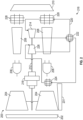
- the aircraft propulsion system 200 may be configured to be mounted to an aircraft to generate propulsive force for flight.
- the aircraft propulsion system 200 includes an air inlet 202, a fan 204 (and/or low pressure compressor), a burner 206, a diffuser conduit 208, and an exhaust nozzle 210.
- the fan 204 is arranged along a shaft 212 that is driven by a turbine 214.
- the turbine 214 is part of a closed loop-supercritical fluid system 216.
- a gearing system 218 is arranged between the turbine 214 and the fan 204 along the shaft 212.
- the gearing system 218 is configured to transition a high speed rotation from the turbine 214 to a lower speed rotation for the fan 204.
- the closed loop-supercritical fluid system 216 is a closed loop system containing a supercritical fluid within a fluid line 220.
- the supercritical fluid may be CO 2 .
- the closed loop-supercritical fluid system 216 includes the turbine 214, an optional recuperator heat exchanger 222, a cooler heat exchanger 224, a compressor 226, and a recovery heat exchanger 228.
- the supercritical fluid passes through the fluid line 220 it will drive the turbine 214 which in turn drives rotation of the shaft 212.
- the compressor 226 and the fan 204 are coupled to the shaft 212 and thus are driven by the turbine 214.
- the supercritical fluid will be directed to the optional recuperator heat exchanger 222.
- the recuperator heat exchanger 222 is a supercritical fluid-to-supercritical fluid heat exchanger with both flow paths through the recuperator heat exchanger 222 containing the supercritical fluid.
- the supercritical fluid will then flow into the cooler heat exchanger 224, or directly to the cooler heat exchanger 224 if no recuperator heat exchanger 222 is present.
- the cooler heat exchanger 224 is configured to cool the supercritical fluid.
- the cooler heat exchanger 224 may be an air-to-supercritical fluid or fuel-to-supercritical fluid heat exchanger.
- the cooler heat exchanger 224 is employed to reject heat of the supercritical fluid (e.g., sCO 2 ) into the air stream forward of the burner 206 and is then recovered into the air stream that feeds the recovery heat exchanger 228.
- the cooler heat exchanger 224 may be arranged in a duct, such as a bypass duct or bypass stream 231 of the aircraft propulsion system 200, such as downstream from the air inlet 202 and downstream of the fan 204.
- the bypass duct would direct air from the air inlet 202 toward the exhaust nozzle 210 without the air interacting with other components and, in some embodiment, may be the primary thrust generator of the aircraft propulsion system 200.
- the cooler heat exchanger 224 may receive a fuel to be provided into the burner 206 for combustion and provide heat exchange between the fuel and the supercritical fluid.
- the fuel may be jet fuel, biofuels, or cryogenic fuels (e.g., hydrogen, methane, etc.).
- the supercritical fluid will then pass into the compressor 226, which is driven on the shaft 212 by the turbine 214.
- the supercritical fluid will then flow through the optional recuperator heat exchanger 222, if present, and into the recovery heat exchanger 228.
- the recovery heat exchanger 228 may be an annular structure arranged about and/or proximate to the exhaust nozzle 210. Hot gases from the burner(s) 206 will flow along the diffuser conduit 208 and into the recovery heat exchanger 228.
- the supercritical fluid will experience heat pickup within the recovery heat exchanger 228 which takes advantage of the waste heat generated by the burner(s) 206.
- the heated supercritical fluid will then enter the turbine 214 and drive rotation thereof.
- the closed loop-supercritical fluid system 216 provides the primary driving force for rotating the shaft 212.
- the second is an air flow path that passes through the aircraft propulsion system 200.
- the bulk of the air will enter at the air inlet 202, be driven by the fan 204, and then pass through a bypass channel to provide thrust.
- a portion of the air will be directed from the fan 204 into the burner 206 to be combusted with a fuel, such as jet fuel, hydrogen, or the like.
- the combusted fuel and air will be passed into and through the diffuser conduit 208 prior to entering the recovery heat exchanger 228 and then exit the aircraft propulsion system 200 through the exhaust nozzle 210.
- This exhaust will generate some amount of thrust to supplement the primary thrust generator in a bypass, with the bypass being similar to that shown and described with respect to FIG. 1 and/or as otherwise described herein.
- the aircraft propulsion system 200 is distinct from prior gas turbine engines, particularly in that the primary driving force to drive the fan 202 is not a convention combustor-turbine configuration.
- the combusted fuel is not the primary driving force, but rather the closed-loop cycle of the closed loop-supercritical fluid system 216 provides the motive force to drive the fan 202 and generate thrust for flight.
- the closed loop-supercritical fluid system 216 is a closed-loop system, there is no requirement for a direct fuel injection or reliance upon the fuel itself.
- the closed-loop cycle enables elimination of efficiency dependency that is due to a density drop associated with altitude changes when using traditional jet engines. That is, the aircraft propulsion system 200 provides for an altitude-invariant engine. As a result, embodiments of the present disclosure provide for systems having effectively no efficiency lapse due to altitude.
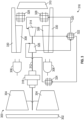
- FIG. 3 a schematic diagram of an aircraft propulsion system 300 in accordance with an embodiment of the present disclosure is shown.
- the aircraft propulsion system 300 may be substantially similar to that shown in FIG. 2 .
- the aircraft propulsion system 300 includes an air inlet 302, a fan 304 (and/or low pressure compressor), a burner 306, a diffuser conduit 308, and an exhaust nozzle 310.
- the fan 304 is arranged along a shaft 312 that is driven by a turbine 314 of a closed loop-supercritical fluid system 316, similar to that described above.
- a gearing system 318 is arranged between the turbine 314 and the fan 304 along the shaft 312.
- the gearing system 318 is configured to transition a high speed rotation from the turbine 314 to a lower speed rotation for the fan 304.
- the closed loop-supercritical fluid system 316 is a closed loop system containing a supercritical fluid within a fluid line 320.
- the closed loop-supercritical fluid system 316 includes the turbine 314, an optional recuperator heat exchanger 322, a cooler heat exchanger 324, a compressor 326, and a recovery heat exchanger 328.
- the cooler heat exchanger 324 may be arranged between the fan 304 and the burner 306. As such, heat from the supercritical fluid may be rejected into the air stream forward of the burner 306 and be recovered into the air stream that feeds the recovery heat exchanger 228.
- the cooler heat exchanger 224 can be optionally arranged within a bypass stream of the system.
- As the supercritical fluid passes through the fluid line 320 it will drive the turbine 314 which in turn drives rotation of the shaft 312.
- the compressor 326 and the fan 304 are coupled to the shaft 312 and thus are driven by the turbine 314.
- a heat exchanger bypass 330 is arranged along the flow path of the air that passes from the fan 304 to the exhaust nozzle 310.
- a portion of the combusted gases exiting the burner 306 may be used to provide additional thrust, without a portion of the energy extracted within the recovery heat exchanger 328.
- this configuration can potentially generate additional thrust through air passing through the heat exchanger bypass 330.
- the size of the recovery heat exchanger 328 may be smaller than the similar recovery heat exchanger 228 in the configuration of FIG. 2 . This is because less air is passing through the recovery heat exchanger 328 and thus weight savings may be achieved, while also gaining increased thrust potential.
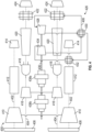
- FIG. 4 a schematic diagram of an aircraft propulsion system 400 in accordance with an embodiment of the present disclosure is shown.
- the aircraft propulsion system 400 may be similar in function as those described above.
- the aircraft propulsion system 400 includes a bypass flow path 402, a hot gas flow path 404, and a closed-loop flow path 406.
- the bypass flow path 402 is an air flow path that generates the majority of the thrust for the aircraft propulsion system 400. Air enters the bypass flow path 402 at an air inlet 408. The air is driven by a rotating fan 410 into a bypass duct 412. The air is then ejected or driven out of a bypass nozzle 414.
- the hot gas flow path 404 is also an air flow path that is used to generate heat for the aircraft propulsion system 400.
- Air is sourced from the air inlet 408, passed through the fan 410, and is accelerated through an optional blower 416.
- the accelerated air is then passed through a burner 418 where the air is mixed and combusted with a fuel.
- the hot combusted gas is then passed through a hot stream duct 420 where the flow evens out and reduces turbulence prior to entering a recovery heat exchanger 422 and ejected out a hot stream nozzle 424.
- the closed-loop flow path 406 is part of a closed loop-supercritical fluid system 426 and contains a supercritical fluid within a fluid line.
- the closed loop-supercritical fluid system 426 includes a turbine 428, an optional recuperator heat exchanger 430, a cooler heat exchanger 432, a compressor 434, and the recovery heat exchangers 422. As the supercritical fluid passes through the closed-loop flow path 406 it will drive the turbine 428 which in turn drives rotation of a shaft 436.
- the compressor 434 of the closed-loop flow path 406, the optional blower 416 of the hot gas flow path 404, and the fan 410 of the bypass flow path 402 are each coupled to the shaft 436 and thus are driven by the turbine 428.
- the shaft 436 may include one or more gear systems 438a, 438b.
- the gear systems 438a, 438b may be configured to step the rotational speed of the shaft to appropriately drive the optional blower 416 and/or the fan 410.
- the gear systems may be configured to provide an overall gear ratio across both gear systems 438a, 438b between 10:1 to 20:1, although other gear ratios and gearing may be employed without departing from the scope of the present disclosure, as will be appreciated by those of skill in the art.
- the cooler heat exchanger 432 of the closed-loop flow path 406 is arranged within the bypass duct 412 of the bypass flow path 402.
- the cooler heat exchanger 432 in this embodiment is an air-to-supercritical fluid heat exchanger.
- FIG. 5 a schematic diagram of an aircraft propulsion system 500 in accordance with an embodiment of the present disclosure is shown.
- the aircraft propulsion system 500 may be similar in function as those described above.
- the aircraft propulsion system 500 includes a bypass flow path 502, a hot gas flow path 504, a closed-loop flow path 506, and a fuel flow path 540.
- the bypass flow path 502 is an air flow path that generates the majority of the thrust for the aircraft propulsion system 500. Air enters the bypass flow path 502 at an air inlet 508. The air is driven by a rotating fan 510 into a bypass duct 512. The air is then ejected or driven out of a bypass nozzle 514.
- the hot gas flow path 504 is also an air flow path that is used to generate heat for the aircraft propulsion system 500.
- Air is sourced from the air inlet 508, passed through the fan 510, and is accelerated through a blower 516.
- the accelerated air is then passed through a burner 518 where the air is mixed and combusted with a fuel.
- the hot combusted gas is then passed through a hot stream duct 520 where the flow evens out and reduces turbulence prior to entering a recovery heat exchanger 522 and ejected out a hot stream nozzle 524.
- an optional pump 523 may be arranged upstream of recovery heat exchanger 522.
- the potential phase change to liquid within the closed-loop flow path 506 may enable the use of pumps. Such pumping may enable boosting the working fluid within the closed-loop flow path 506 to a higher pressure that may reduce the required compression work, thus improving overall efficiencies.
- the closed-loop flow path 506 is part of a closed loop-supercritical fluid system 526 and contains a supercritical fluid within a fluid line.
- the closed loop-supercritical fluid system 526 includes a turbine 528, an optional recuperator heat exchanger 530, a cooler heat exchanger 532, a compressor 534, and the recovery heat exchangers 522.
- the fuel flow path 540 is configured to supply fuel from a fuel tank 542 to the burner 518 for combustion with the air in the hot gas flow path 504.
- the fuel flow path 540 is part of a cryogenic fuel system 544.
- the cryogenic fuel system 544 provides a supply of fuel that is stored in a cryogenic state (such as liquid hydrogen or the like).
- the fuel is extracted from the fuel tank 542 (e.g., by a pump or the like) and passed through a power electronics heat exchanger 546 that begins the warming process of the fuel from its cryogenic state.
- an additional heat exchanger may be arranged within a fan stream of the engine, as discussed above, which can result in reduced size heat exchangers throughout the system.
- the cooler heat exchanger 532 provides the cryogenic fuel as a cold sink side for the hot working fluid passing through the closed-loop flow path 506.
- an additional heat exchanger may be arranged downstream of the cooler heat exchanger 532, in a similar fan stream position to, for example, cooler heat exchanger 432 shown in FIG. 4 . That is, there may be multiple cooler heat exchanges arranged along the closed-loop flow path 506 and arranged in different arrangements along the closed-loop flow path 506 based on thermal considerations, for example, and/or upon physical limitations of the specific engine configurations.
- the fuel is then passed through the cooler heat exchanger 532 of the closed-loop flow path 506 where the fuel picks up heat from the fluid of the closed-loop flow path 506.
- the fuel is then passed through a turbo expander 548 and subsequently supplied into the burner 518 for combustion with the air of the hot gas flow path 504.
- the cryogenic fuel could be passed through other engine and/or aircraft heat exchangers as a coolant prior to entering the combustor, and the present flow path is not to be limiting.
- the compressor 534 of the closed-loop flow path 506, the blower 516 of the hot gas flow path 504, the fan 510 of the bypass flow path 502, and the turbo expander 548 of the fuel flow path 540 are each coupled to the shaft 536 and thus are driven by the turbine 528.
- the shaft 536 may include one or more gear systems 538a, 538b.
- the gear systems 538a, 538b may be configured to step the rotational speed of the shaft to appropriately drive the blower 516, the turbo expander 548, and/or the fan 510.
- the schematic illustrations herein are more diagrams rather than structural configurations. Further, although it may appear that two of each element are illustrated, such may not be the case, rather a single structure or a multiple of different components may be included.
- the ducts and fans illustrated as two separate structures may in fact be portions of an annular structure.
- the elements may be representative of multiple components arranged about a central axis.
- the burners may be a number of discrete and separate burners (e.g., combustion chambers) arranged about a central axis, which may be defined by the shaft of the propulsion systems described herein.
- the illustrations are not to be limiting but rather are provided for explanatory and illustrative purposes only, as described herein.
- FIG. 6 a schematic illustration of an aircraft 600 that may incorporate embodiments of the present disclosure is shown.
- the aircraft 600 includes a fuselage 602, wings 604, and a tail 606.
- the aircraft 600 includes wing-mounted aircraft propulsion systems 608.
- the wing-mounted aircraft propulsion systems 608 may be arranged as the aircraft propulsion systems shown and described above. It will be appreciated that other aircraft configurations may employ the propulsion systems of the present disclosure without departing from the scope of the present disclosure.
- fuselage-mounted and/or tail-mounted configurations are possible.
- any number of propulsion systems may be employed, from one to four or more, depending on the aircraft configuration and power and thrust needs thereof.
- embodiments of the present disclosure provide for an alternative aircraft propulsion system that may generate less waste and/or pollutants while providing improved efficiency that is not dependent upon altitude.
- Such aircraft propulsion systems may be zero or near-zero CO 2 emission aircraft propulsion systems.
- a new engine architecture is provided herein where the primary motive force is provided from a closed-loop cycle, rather than the conventional air-breathing Brayton cycles that primarily rely upon combustion to drive rotation of a shaft. Accordingly, the amount of fuel may be reduced, the size of components may be optimized, and improved efficiencies may be achieved.
- an altitude invariant engine design is provided by embodiments of the present disclosure. Further, improved thermal efficiencies of flight-ready engines are provided by the configurations described herein.
- the term "about” is intended to include the degree of error associated with measurement of the particular quantity based upon the equipment available at the time of filing the application. For example, “about” may include a range of ⁇ 8%, or 5%, or 2% of a given value or other percentage change as will be appreciated by those of skill in the art for the particular measurement and/or dimensions referred to herein.
Landscapes
- Engineering & Computer Science (AREA)
- Chemical & Material Sciences (AREA)
- Combustion & Propulsion (AREA)
- Mechanical Engineering (AREA)
- General Engineering & Computer Science (AREA)
- Structures Of Non-Positive Displacement Pumps (AREA)
Claims (15)
- Flugzeugantriebssystem (200; 300; 400; 500), umfassend:ein geschlossenes System für überkritische Fluide (216; 316; 426; 526), das eine Turbine (214; 314; 428; 528), einen Kühler-Wärmetauscher (224; 324; 432; 532), einen Verdichter (226; 326; 434; 534) und einen Rückgewinnungs-Wärmetauscher (228; 328; 422; 522) aufweist, die entlang eines geschlossenen Strömungswegs (220; 320; 406; 506) eines überkritischen Fluids angeordnet sind;eine Welle (212; 312; 436; 536), die mit der Turbine (214...528) wirkgekoppelt und dazu konfiguriert ist, von der Turbine (214...528) rotierend angetrieben zu werden, wobei der Verdichter (226...534) auf der Welle (212...536) angeordnet und dazu konfiguriert ist, von der Welle (212...536) rotierend angetrieben zu werden;einen Fan (204; 304; 410; 510), der dazu konfiguriert ist, Schub zu erzeugen, wobei der Fan (204...520) mit der Welle (212...536) wirkgekoppelt ist, um von der Welle (212...536) rotierend angetrieben zu werden; undeinen Brenner (206; 306; 418; 518), der dazu konfiguriert ist, einen Kraftstoff und Luft von dem Fan (204...510) zu verbrennen, um ein verbranntes Gas zu erzeugen und das verbrannte Gas dem Rückgewinnungs-Wärmetauscher (228...522) des geschlossenen Systems für überkritische Fluide (216...526) und aus einer Abgasdüse (210; 310; 424; 524) zuzuführen,gekennzeichnet durch:
einen Diffusorkanal (208; 308), der zwischen dem Brenner (206; 306) und dem Rückgewinnungs-Wärmetauscher (228; 338) angeordnet ist, wobei der Brenner (206; 306) so angeordnet ist, dass er verbrannten Kraftstoff und Luft in den Diffusorkanal (208; 308) leitet, und der Rückgewinnungs-Wärmetauscher (228; 338) stromabwärts von dem Diffusorkanal (208; 308) angeordnet ist, und der Diffusorkanal (208; 308) dazu konfiguriert ist, ein Strömungsprofil des verbrannten Gases vor dem Eintritt in den Rückgewinnungs-Wärmetauscher (228; 338) zu verlangsamen und zu homogenisieren. - Flugzeugantriebssystem nach Anspruch 1, wobei das überkritische Fluid CO2 ist, das durch die Turbine (214...528), den Kühler-Wärmetauscher (224...532), den Verdichter (226...534) und den Rückgewinnungs-Wärmetauscher (228...522) geströmt wird.
- Flugzeugantriebssystem nach Anspruch 1 oder 2, ferner umfassend ein Getriebesystem (218; 318; 438a, 438b; 538a, 538b), das mit der Welle (212...536) zwischen der Turbine (214...528) und dem Fan (204...510) gekoppelt ist.
- Flugzeugantriebssystem nach einem der vorhergehenden Ansprüche, wobei das geschlossene System für überkritische Fluide (216...526) ferner einen Rekuperator-Wärmetauscher (222; 322; 430; 530) umfasst, der zwischen der Turbine (214...528) und dem Kühler-Wärmetauscher (224; 532) entlang des geschlossenen Strömungswegs (220...506) angeordnet ist.
- Flugzeugantriebssystem nach Anspruch 4, wobei der Rekuperator-Wärmetauscher (222 ... 530) ein Wärmetauscher von überkritischem Fluid zu überkritischem Fluid ist.
- Flugzeugantriebssystem nach einem der vorhergehenden Ansprüche, ferner umfassend einen kryogenen Kraftstofftank (542), der dazu konfiguriert ist, dem Brenner (518) Kraftstoff durch einen Kraftstoffströmungsweg (540) zuzuführen, wobei der Kühler-Wärmetauscher (532) ein Wärmetauscher von Kraftstoff zu überkritischem Fluid ist.
- Flugzeugantriebssystem nach Anspruch 6, ferner umfassend einen Turboexpander (548), der mit der Welle (536) wirkgekoppelt und zwischen dem kryogenen Kraftstofftank (542) und dem Brenner (518) angeordnet ist.
- Flugzeugantriebssystem nach einem der vorhergehenden Ansprüche, wobei der Kühler-Wärmetauscher (224...532) ein Wärmetauscher von Luft zu überkritischem Fluid ist und/oder der Kühler-Wärmetauscher (224...532) innerhalb eines Bypass-Kanals (231; 412; 512) stromabwärts des Fans (204...510) angeordnet ist.
- Flugzeugantriebssystem (400) nach Anspruch 1, ferner umfassend:einen Bypass-Strömungsweg (402; 502), der einen Strömungsweg von Luft definiert, die durch einen Lufteinlass (202; 302; 408; 508), durch den Fan (204...510), durch einen Bypass-Kanal (231; 412; 512) und aus einer Bypass-Düse (514; 414) strömt;einen Heißgasströmungsweg (404; 504), der einen Strömungsweg von Luft definiert, die durch den Lufteinlass (202...508), durch den Fan (204...510), in den Brenner (206...518) zur Verbrennung mit Kraftstoff, um verbranntes Gas zu erzeugen, und durch den Rückgewinnungs-Wärmetauscher (228...522) und aus der Abgasdüse (210...524) strömt; undeinen geschlossenen Strömungsweg (220; 320; 406; 506), der einen geschlossenen Strömungsweg eines überkritischen Fluids definiert, das durch die Turbine (214...528), die mit der Welle (212...536) wirkgekoppelt ist, um die Drehung der Welle (212...536) anzutreiben, den Kühler-Wärmetauscher (224...532), den Verdichter (226...534), der mit der Welle (212...536) gekoppelt ist, in den Rückgewinnungs-Wärmetauscher (228...522) und zurück zu der Turbine (214...528) strömt,wobei die Turbine (214...528) des geschlossenen Strömungswegs (406; 506) die Drehung der Welle (212...536), des Verdichters (226...534) und des Fans (204...510) antreibt.
- Flugzeugantriebssystem nach Anspruch 9, ferner umfassend einen Kraftstoffströmungsweg (540), der einen Strömungsweg von einem Kraftstofftank (542) zu dem Brenner (518) des Heißgasströmungswegs (504) definiert.
- Flugzeugantriebssystem nach Anspruch 10, wobei ein Kraftstoff in dem Kraftstoffströmungsweg (540) kryogener Kraftstoff ist und der kryogene Kraftstoff optional Wasserstoff ist.
- Flugzeugantriebssystem nach Anspruch 9, 10 oder 11, ferner umfassend einen Turboexpander (548), der mit der Welle (536) gekoppelt und dazu konfiguriert ist, einen Kraftstoff vor der Einspritzung in den Brenner (518) zu expandieren.
- Flugzeugantriebssystem nach Anspruch 12, ferner umfassend ein erstes Getriebesystem (538a), das mit der Welle (536) zwischen der Turbine (528) und dem Turboexpander (548) gekoppelt ist, und ein zweites Getriebesystem (538b), das mit der Welle zwischen dem Turboexpander (548) und dem Fan (510) gekoppelt ist.
- Flugzeugantriebssystem nach Anspruch 9 bis 13, wobei der Kühler-Wärmetauscher (224 ... 532) des geschlossenen Strömungswegs (220 ... 506) dazu konfiguriert ist, Kraftstoff zu empfangen, um einen Wärmetauscher von Kraftstoff zu überkritischem Fluid zu bilden.
- Flugzeugantriebssystem nach Anspruch 9 bis 14, wobei der Heißgasströmungsweg (404; 504) ferner ein Gebläse (416; 516) umfasst, das zwischen dem Fan (410; 510) und dem Brenner (418; 518) angeordnet ist, um eine Geschwindigkeit der durch den Heißgasströmungsweg (404; 504) strömenden Luft zu erhöhen, und/oder ferner umfassend ein Getriebesystem (218...538b), das mit der Welle (212...536) zwischen der Turbine (214...528) und dem Fan (204...510) gekoppelt ist.
Applications Claiming Priority (1)
| Application Number | Priority Date | Filing Date | Title |
|---|---|---|---|
| US17/407,880 US11754021B2 (en) | 2021-08-20 | 2021-08-20 | Propulsion systems for aircraft |
Publications (2)
| Publication Number | Publication Date |
|---|---|
| EP4137686A1 EP4137686A1 (de) | 2023-02-22 |
| EP4137686B1 true EP4137686B1 (de) | 2025-04-16 |
Family
ID=82939937
Family Applications (1)
| Application Number | Title | Priority Date | Filing Date |
|---|---|---|---|
| EP22190642.3A Active EP4137686B1 (de) | 2021-08-20 | 2022-08-16 | Antriebssysteme für flugzeuge |
Country Status (2)
| Country | Link |
|---|---|
| US (1) | US11754021B2 (de) |
| EP (1) | EP4137686B1 (de) |
Families Citing this family (8)
| Publication number | Priority date | Publication date | Assignee | Title |
|---|---|---|---|---|
| US11305879B2 (en) * | 2018-03-23 | 2022-04-19 | Raytheon Technologies Corporation | Propulsion system cooling control |
| WO2023140891A2 (en) | 2021-07-09 | 2023-07-27 | Raytheon Technologies Corporation | Turbine engines having hydrogen fuel systems |
| GB202203007D0 (en) * | 2022-03-04 | 2022-04-20 | Rolls Royce Plc | Combined cycles |
| US11987377B2 (en) * | 2022-07-08 | 2024-05-21 | Rtx Corporation | Turbo expanders for turbine engines having hydrogen fuel systems |
| US12103699B2 (en) | 2022-07-08 | 2024-10-01 | Rtx Corporation | Hybrid electric power for turbine engines having hydrogen fuel systems |
| CN116733559B (zh) * | 2023-06-05 | 2025-05-09 | 浙江大学 | 耦合燃料潜热的二氧化碳变布雷顿冷电联供系统和方法 |
| US12460577B2 (en) | 2024-03-27 | 2025-11-04 | Rtx Corporation | AFT gear based engine with heat recovery system |
| US20260036089A1 (en) * | 2024-08-02 | 2026-02-05 | Rtx Corporation | Cryogenic fuel semi-closed recirculating bottoming cycle |
Family Cites Families (10)
| Publication number | Priority date | Publication date | Assignee | Title |
|---|---|---|---|---|
| WO2010121255A1 (en) * | 2009-04-17 | 2010-10-21 | Echogen Power Systems | System and method for managing thermal issues in gas turbine engines |
| WO2013087916A1 (en) | 2011-12-15 | 2013-06-20 | Nestec S.A. | Extensional viscosity to promote safe swallowing of food boluses |
| US9885283B2 (en) | 2014-06-05 | 2018-02-06 | Rolls-Royce Corporation | Gas turbine engine driven by supercritical power generation system |
| GB2531775B (en) * | 2014-10-30 | 2018-05-09 | Rolls Royce Plc | A gas turbine using cryogenic fuel passed through a fuel turbine |
| US10443544B2 (en) * | 2015-06-15 | 2019-10-15 | Rolls-Royce Corporation | Gas turbine engine driven by sCO2 cycle with advanced heat rejection |
| EP3109433B1 (de) | 2015-06-19 | 2018-08-15 | Rolls-Royce Corporation | Motor, angetrieben durch sc02 mit unabhängigen wellen für verbrennungszykluselemente und antriebselemente |
| EP3153690B1 (de) * | 2015-10-08 | 2025-06-04 | Rolls-Royce Corporation | Nur-co2-flugzeug |
| US10364744B2 (en) * | 2016-06-08 | 2019-07-30 | Rolls-Royce Corporation | Deep heat recovery gas turbine engine |
| US11434823B2 (en) * | 2020-01-06 | 2022-09-06 | Raytheon Technologies Corporation | Systems and methods for power transfer in cryogenic fuel applications |
| US11480102B2 (en) * | 2020-05-01 | 2022-10-25 | Hamilton Sundstrand Corporation | Gearbox mechanically coupled fuel cell and CO2 combined cycle power generation |
-
2021
- 2021-08-20 US US17/407,880 patent/US11754021B2/en active Active
-
2022
- 2022-08-16 EP EP22190642.3A patent/EP4137686B1/de active Active
Also Published As
| Publication number | Publication date |
|---|---|
| US20230056536A1 (en) | 2023-02-23 |
| EP4137686A1 (de) | 2023-02-22 |
| US11754021B2 (en) | 2023-09-12 |
Similar Documents
| Publication | Publication Date | Title |
|---|---|---|
| EP4137686B1 (de) | Antriebssysteme für flugzeuge | |
| EP4019752B1 (de) | Gasturbinentriebwerke mit kryokraftstoffsystemen | |
| US11391211B2 (en) | Waste heat recovery system | |
| EP3296543B1 (de) | Gasturbinenmotor mit zwischengekühlter kühlluft und turbinenantrieb | |
| US11236639B2 (en) | Gas turbine engine and an airflow control system | |
| US10641169B2 (en) | Hybrid combustor assembly and method of operation | |
| US12281850B2 (en) | Multi-fluid heat exchanger | |
| US20210140641A1 (en) | Method and system for rotating detonation combustion | |
| US20180231256A1 (en) | Rotating Detonation Combustor | |
| EP3039264B1 (de) | Gasturbinenmotordiffusorkühl- und -mischanordnung | |
| US20180356099A1 (en) | Bulk swirl rotating detonation propulsion system | |
| US12037943B2 (en) | Waste heat recovery system | |
| US10337401B2 (en) | Turbine engine with a turbo-compressor | |
| US20240102417A1 (en) | Air recuperated engine with air reinjection | |
| EP4303416A1 (de) | Turboexpander für turbinenmotoren mit wasserstoffbrennstoffsystemen | |
| US20220389884A1 (en) | Variable cycle jet engine | |
| US12031478B2 (en) | Air bottoming cycle driven propulsor | |
| US12163488B1 (en) | Selectable inlet for aircraft propulsion system heat exchanger | |
| US20250290445A1 (en) | Hydrogen fuel heating with open loop waste heat recovery cycle | |
| EP4431702A1 (de) | Dampfgekühlte turbinenleitschaufelanordnung | |
| EP4311917A1 (de) | Ablassloch-flussstoppvorrichtung | |
| CN117988985A (zh) | 用于燃气涡轮发动机的空气导向件 |
Legal Events
| Date | Code | Title | Description |
|---|---|---|---|
| PUAI | Public reference made under article 153(3) epc to a published international application that has entered the european phase |
Free format text: ORIGINAL CODE: 0009012 |
|
| STAA | Information on the status of an ep patent application or granted ep patent |
Free format text: STATUS: THE APPLICATION HAS BEEN PUBLISHED |
|
| AK | Designated contracting states |
Kind code of ref document: A1 Designated state(s): AL AT BE BG CH CY CZ DE DK EE ES FI FR GB GR HR HU IE IS IT LI LT LU LV MC MK MT NL NO PL PT RO RS SE SI SK SM TR |
|
| STAA | Information on the status of an ep patent application or granted ep patent |
Free format text: STATUS: REQUEST FOR EXAMINATION WAS MADE |
|
| 17P | Request for examination filed |
Effective date: 20230818 |
|
| RBV | Designated contracting states (corrected) |
Designated state(s): AL AT BE BG CH CY CZ DE DK EE ES FI FR GB GR HR HU IE IS IT LI LT LU LV MC MK MT NL NO PL PT RO RS SE SI SK SM TR |
|
| RAP3 | Party data changed (applicant data changed or rights of an application transferred) |
Owner name: RTX CORPORATION |
|
| GRAP | Despatch of communication of intention to grant a patent |
Free format text: ORIGINAL CODE: EPIDOSNIGR1 |
|
| STAA | Information on the status of an ep patent application or granted ep patent |
Free format text: STATUS: GRANT OF PATENT IS INTENDED |
|
| INTG | Intention to grant announced |
Effective date: 20241108 |
|
| GRAS | Grant fee paid |
Free format text: ORIGINAL CODE: EPIDOSNIGR3 |
|
| GRAA | (expected) grant |
Free format text: ORIGINAL CODE: 0009210 |
|
| STAA | Information on the status of an ep patent application or granted ep patent |
Free format text: STATUS: THE PATENT HAS BEEN GRANTED |
|
| AK | Designated contracting states |
Kind code of ref document: B1 Designated state(s): AL AT BE BG CH CY CZ DE DK EE ES FI FR GB GR HR HU IE IS IT LI LT LU LV MC MK MT NL NO PL PT RO RS SE SI SK SM TR |
|
| REG | Reference to a national code |
Ref country code: GB Ref legal event code: FG4D |
|
| REG | Reference to a national code |
Ref country code: CH Ref legal event code: EP |
|
| REG | Reference to a national code |
Ref country code: IE Ref legal event code: FG4D |
|
| REG | Reference to a national code |
Ref country code: DE Ref legal event code: R096 Ref document number: 602022013166 Country of ref document: DE |
|
| REG | Reference to a national code |
Ref country code: NL Ref legal event code: MP Effective date: 20250416 |
|
| PG25 | Lapsed in a contracting state [announced via postgrant information from national office to epo] |
Ref country code: NL Free format text: LAPSE BECAUSE OF FAILURE TO SUBMIT A TRANSLATION OF THE DESCRIPTION OR TO PAY THE FEE WITHIN THE PRESCRIBED TIME-LIMIT Effective date: 20250416 |
|
| REG | Reference to a national code |
Ref country code: AT Ref legal event code: MK05 Ref document number: 1785835 Country of ref document: AT Kind code of ref document: T Effective date: 20250416 |
|
| PG25 | Lapsed in a contracting state [announced via postgrant information from national office to epo] |
Ref country code: FI Free format text: LAPSE BECAUSE OF FAILURE TO SUBMIT A TRANSLATION OF THE DESCRIPTION OR TO PAY THE FEE WITHIN THE PRESCRIBED TIME-LIMIT Effective date: 20250416 Ref country code: ES Free format text: LAPSE BECAUSE OF FAILURE TO SUBMIT A TRANSLATION OF THE DESCRIPTION OR TO PAY THE FEE WITHIN THE PRESCRIBED TIME-LIMIT Effective date: 20250416 Ref country code: PT Free format text: LAPSE BECAUSE OF FAILURE TO SUBMIT A TRANSLATION OF THE DESCRIPTION OR TO PAY THE FEE WITHIN THE PRESCRIBED TIME-LIMIT Effective date: 20250818 |
|
| PGFP | Annual fee paid to national office [announced via postgrant information from national office to epo] |
Ref country code: DE Payment date: 20250724 Year of fee payment: 4 |
|
| REG | Reference to a national code |
Ref country code: LT Ref legal event code: MG9D |
|
| PG25 | Lapsed in a contracting state [announced via postgrant information from national office to epo] |
Ref country code: NO Free format text: LAPSE BECAUSE OF FAILURE TO SUBMIT A TRANSLATION OF THE DESCRIPTION OR TO PAY THE FEE WITHIN THE PRESCRIBED TIME-LIMIT Effective date: 20250716 Ref country code: GR Free format text: LAPSE BECAUSE OF FAILURE TO SUBMIT A TRANSLATION OF THE DESCRIPTION OR TO PAY THE FEE WITHIN THE PRESCRIBED TIME-LIMIT Effective date: 20250717 |
|
| PG25 | Lapsed in a contracting state [announced via postgrant information from national office to epo] |
Ref country code: PL Free format text: LAPSE BECAUSE OF FAILURE TO SUBMIT A TRANSLATION OF THE DESCRIPTION OR TO PAY THE FEE WITHIN THE PRESCRIBED TIME-LIMIT Effective date: 20250416 |
|
| PG25 | Lapsed in a contracting state [announced via postgrant information from national office to epo] |
Ref country code: BG Free format text: LAPSE BECAUSE OF FAILURE TO SUBMIT A TRANSLATION OF THE DESCRIPTION OR TO PAY THE FEE WITHIN THE PRESCRIBED TIME-LIMIT Effective date: 20250416 |
|
| PG25 | Lapsed in a contracting state [announced via postgrant information from national office to epo] |
Ref country code: HR Free format text: LAPSE BECAUSE OF FAILURE TO SUBMIT A TRANSLATION OF THE DESCRIPTION OR TO PAY THE FEE WITHIN THE PRESCRIBED TIME-LIMIT Effective date: 20250416 |
|
| PG25 | Lapsed in a contracting state [announced via postgrant information from national office to epo] |
Ref country code: AT Free format text: LAPSE BECAUSE OF FAILURE TO SUBMIT A TRANSLATION OF THE DESCRIPTION OR TO PAY THE FEE WITHIN THE PRESCRIBED TIME-LIMIT Effective date: 20250416 |
|
| PGFP | Annual fee paid to national office [announced via postgrant information from national office to epo] |
Ref country code: FR Payment date: 20250723 Year of fee payment: 4 |
|
| PG25 | Lapsed in a contracting state [announced via postgrant information from national office to epo] |
Ref country code: RS Free format text: LAPSE BECAUSE OF FAILURE TO SUBMIT A TRANSLATION OF THE DESCRIPTION OR TO PAY THE FEE WITHIN THE PRESCRIBED TIME-LIMIT Effective date: 20250716 |
|
| PG25 | Lapsed in a contracting state [announced via postgrant information from national office to epo] |
Ref country code: IS Free format text: LAPSE BECAUSE OF FAILURE TO SUBMIT A TRANSLATION OF THE DESCRIPTION OR TO PAY THE FEE WITHIN THE PRESCRIBED TIME-LIMIT Effective date: 20250816 |
|
| PG25 | Lapsed in a contracting state [announced via postgrant information from national office to epo] |
Ref country code: LV Free format text: LAPSE BECAUSE OF FAILURE TO SUBMIT A TRANSLATION OF THE DESCRIPTION OR TO PAY THE FEE WITHIN THE PRESCRIBED TIME-LIMIT Effective date: 20250416 |
|
| PG25 | Lapsed in a contracting state [announced via postgrant information from national office to epo] |
Ref country code: DK Free format text: LAPSE BECAUSE OF FAILURE TO SUBMIT A TRANSLATION OF THE DESCRIPTION OR TO PAY THE FEE WITHIN THE PRESCRIBED TIME-LIMIT Effective date: 20250416 Ref country code: SM Free format text: LAPSE BECAUSE OF FAILURE TO SUBMIT A TRANSLATION OF THE DESCRIPTION OR TO PAY THE FEE WITHIN THE PRESCRIBED TIME-LIMIT Effective date: 20250416 |
|
| REG | Reference to a national code |
Ref country code: DE Ref legal event code: R097 Ref document number: 602022013166 Country of ref document: DE |
|
| PG25 | Lapsed in a contracting state [announced via postgrant information from national office to epo] |
Ref country code: CZ Free format text: LAPSE BECAUSE OF FAILURE TO SUBMIT A TRANSLATION OF THE DESCRIPTION OR TO PAY THE FEE WITHIN THE PRESCRIBED TIME-LIMIT Effective date: 20250416 |
|
| PG25 | Lapsed in a contracting state [announced via postgrant information from national office to epo] |
Ref country code: EE Free format text: LAPSE BECAUSE OF FAILURE TO SUBMIT A TRANSLATION OF THE DESCRIPTION OR TO PAY THE FEE WITHIN THE PRESCRIBED TIME-LIMIT Effective date: 20250416 |
|
| PG25 | Lapsed in a contracting state [announced via postgrant information from national office to epo] |
Ref country code: SK Free format text: LAPSE BECAUSE OF FAILURE TO SUBMIT A TRANSLATION OF THE DESCRIPTION OR TO PAY THE FEE WITHIN THE PRESCRIBED TIME-LIMIT Effective date: 20250416 |
|
| PG25 | Lapsed in a contracting state [announced via postgrant information from national office to epo] |
Ref country code: IT Free format text: LAPSE BECAUSE OF FAILURE TO SUBMIT A TRANSLATION OF THE DESCRIPTION OR TO PAY THE FEE WITHIN THE PRESCRIBED TIME-LIMIT Effective date: 20250416 |
|
| PG25 | Lapsed in a contracting state [announced via postgrant information from national office to epo] |
Ref country code: RO Free format text: LAPSE BECAUSE OF FAILURE TO SUBMIT A TRANSLATION OF THE DESCRIPTION OR TO PAY THE FEE WITHIN THE PRESCRIBED TIME-LIMIT Effective date: 20250416 |
|
| PLBE | No opposition filed within time limit |
Free format text: ORIGINAL CODE: 0009261 |
|
| STAA | Information on the status of an ep patent application or granted ep patent |
Free format text: STATUS: NO OPPOSITION FILED WITHIN TIME LIMIT |
|
| REG | Reference to a national code |
Ref country code: CH Ref legal event code: L10 Free format text: ST27 STATUS EVENT CODE: U-0-0-L10-L00 (AS PROVIDED BY THE NATIONAL OFFICE) Effective date: 20260225 |
|
| REG | Reference to a national code |
Ref country code: CH Ref legal event code: H13 Free format text: ST27 STATUS EVENT CODE: U-0-0-H10-H13 (AS PROVIDED BY THE NATIONAL OFFICE) Effective date: 20260324 |
|
| 26N | No opposition filed |
Effective date: 20260119 |