EP4147977B1 - Wärmesteuerungssystem mit doppel-kondensatoren - Google Patents
Wärmesteuerungssystem mit doppel-kondensatoren Download PDFInfo
- Publication number
- EP4147977B1 EP4147977B1 EP22195471.2A EP22195471A EP4147977B1 EP 4147977 B1 EP4147977 B1 EP 4147977B1 EP 22195471 A EP22195471 A EP 22195471A EP 4147977 B1 EP4147977 B1 EP 4147977B1
- Authority
- EP
- European Patent Office
- Prior art keywords
- coolant
- arrangement
- propeller
- management system
- path
- Prior art date
- Legal status (The legal status is an assumption and is not a legal conclusion. Google has not performed a legal analysis and makes no representation as to the accuracy of the status listed.)
- Active
Links
Images


Classifications
-
- B—PERFORMING OPERATIONS; TRANSPORTING
- B64—AIRCRAFT; AVIATION; COSMONAUTICS
- B64D—EQUIPMENT FOR FITTING IN OR TO AIRCRAFT; FLIGHT SUITS; PARACHUTES; ARRANGEMENT OR MOUNTING OF POWER PLANTS OR PROPULSION TRANSMISSIONS IN AIRCRAFT
- B64D33/00—Arrangement in aircraft of power plant parts or auxiliaries not otherwise provided for
- B64D33/08—Arrangement in aircraft of power plant parts or auxiliaries not otherwise provided for of power plant cooling systems
-
- B—PERFORMING OPERATIONS; TRANSPORTING
- B60—VEHICLES IN GENERAL
- B60H—ARRANGEMENTS OF HEATING, COOLING, VENTILATING OR OTHER AIR-TREATING DEVICES SPECIALLY ADAPTED FOR PASSENGER OR GOODS SPACES OF VEHICLES
- B60H1/00—Heating, cooling or ventilating [HVAC] devices
- B60H1/00271—HVAC devices specially adapted for particular vehicle parts or components and being connected to the vehicle HVAC unit
- B60H1/00278—HVAC devices specially adapted for particular vehicle parts or components and being connected to the vehicle HVAC unit for the battery
-
- B—PERFORMING OPERATIONS; TRANSPORTING
- B60—VEHICLES IN GENERAL
- B60H—ARRANGEMENTS OF HEATING, COOLING, VENTILATING OR OTHER AIR-TREATING DEVICES SPECIALLY ADAPTED FOR PASSENGER OR GOODS SPACES OF VEHICLES
- B60H1/00—Heating, cooling or ventilating [HVAC] devices
- B60H1/00642—Control systems or circuits; Control members or indication devices for heating, cooling or ventilating devices
- B60H1/00814—Control systems or circuits characterised by their output, for controlling particular components of the heating, cooling or ventilating installation
- B60H1/00878—Control systems or circuits characterised by their output, for controlling particular components of the heating, cooling or ventilating installation the components being temperature regulating devices
- B60H1/00899—Controlling the flow of liquid in a heat pump system
-
- B—PERFORMING OPERATIONS; TRANSPORTING
- B64—AIRCRAFT; AVIATION; COSMONAUTICS
- B64D—EQUIPMENT FOR FITTING IN OR TO AIRCRAFT; FLIGHT SUITS; PARACHUTES; ARRANGEMENT OR MOUNTING OF POWER PLANTS OR PROPULSION TRANSMISSIONS IN AIRCRAFT
- B64D27/00—Arrangement or mounting of power plants in aircraft; Aircraft characterised by the type or position of power plants
- B64D27/02—Aircraft characterised by the type or position of power plants
- B64D27/24—Aircraft characterised by the type or position of power plants using steam or spring force
-
- B—PERFORMING OPERATIONS; TRANSPORTING
- B64—AIRCRAFT; AVIATION; COSMONAUTICS
- B64D—EQUIPMENT FOR FITTING IN OR TO AIRCRAFT; FLIGHT SUITS; PARACHUTES; ARRANGEMENT OR MOUNTING OF POWER PLANTS OR PROPULSION TRANSMISSIONS IN AIRCRAFT
- B64D27/00—Arrangement or mounting of power plants in aircraft; Aircraft characterised by the type or position of power plants
- B64D27/02—Aircraft characterised by the type or position of power plants
- B64D27/30—Aircraft characterised by electric power plants
- B64D27/34—All-electric aircraft
-
- B—PERFORMING OPERATIONS; TRANSPORTING
- B64—AIRCRAFT; AVIATION; COSMONAUTICS
- B64D—EQUIPMENT FOR FITTING IN OR TO AIRCRAFT; FLIGHT SUITS; PARACHUTES; ARRANGEMENT OR MOUNTING OF POWER PLANTS OR PROPULSION TRANSMISSIONS IN AIRCRAFT
- B64D27/00—Arrangement or mounting of power plants in aircraft; Aircraft characterised by the type or position of power plants
- B64D27/02—Aircraft characterised by the type or position of power plants
- B64D27/30—Aircraft characterised by electric power plants
- B64D27/35—Arrangements for on-board electric energy production, distribution, recovery or storage
- B64D27/357—Arrangements for on-board electric energy production, distribution, recovery or storage using batteries
-
- B—PERFORMING OPERATIONS; TRANSPORTING
- B64—AIRCRAFT; AVIATION; COSMONAUTICS
- B64D—EQUIPMENT FOR FITTING IN OR TO AIRCRAFT; FLIGHT SUITS; PARACHUTES; ARRANGEMENT OR MOUNTING OF POWER PLANTS OR PROPULSION TRANSMISSIONS IN AIRCRAFT
- B64D33/00—Arrangement in aircraft of power plant parts or auxiliaries not otherwise provided for
- B64D33/08—Arrangement in aircraft of power plant parts or auxiliaries not otherwise provided for of power plant cooling systems
- B64D33/10—Radiator arrangement
-
- F—MECHANICAL ENGINEERING; LIGHTING; HEATING; WEAPONS; BLASTING
- F25—REFRIGERATION OR COOLING; COMBINED HEATING AND REFRIGERATION SYSTEMS; HEAT PUMP SYSTEMS; MANUFACTURE OR STORAGE OF ICE; LIQUEFACTION SOLIDIFICATION OF GASES
- F25B—REFRIGERATION MACHINES, PLANTS OR SYSTEMS; COMBINED HEATING AND REFRIGERATION SYSTEMS; HEAT PUMP SYSTEMS
- F25B41/00—Fluid-circulation arrangements
- F25B41/20—Disposition of valves, e.g. of on-off valves or flow control valves
-
- H—ELECTRICITY
- H01—ELECTRIC ELEMENTS
- H01M—PROCESSES OR MEANS, e.g. BATTERIES, FOR THE DIRECT CONVERSION OF CHEMICAL ENERGY INTO ELECTRICAL ENERGY
- H01M10/00—Secondary cells; Manufacture thereof
- H01M10/60—Heating or cooling; Temperature control
- H01M10/61—Types of temperature control
- H01M10/613—Cooling or keeping cold
-
- H—ELECTRICITY
- H01—ELECTRIC ELEMENTS
- H01M—PROCESSES OR MEANS, e.g. BATTERIES, FOR THE DIRECT CONVERSION OF CHEMICAL ENERGY INTO ELECTRICAL ENERGY
- H01M10/00—Secondary cells; Manufacture thereof
- H01M10/60—Heating or cooling; Temperature control
- H01M10/62—Heating or cooling; Temperature control specially adapted for specific applications
- H01M10/625—Vehicles
-
- H—ELECTRICITY
- H01—ELECTRIC ELEMENTS
- H01M—PROCESSES OR MEANS, e.g. BATTERIES, FOR THE DIRECT CONVERSION OF CHEMICAL ENERGY INTO ELECTRICAL ENERGY
- H01M10/00—Secondary cells; Manufacture thereof
- H01M10/60—Heating or cooling; Temperature control
- H01M10/63—Control systems
- H01M10/635—Control systems based on ambient temperature
-
- H—ELECTRICITY
- H01—ELECTRIC ELEMENTS
- H01M—PROCESSES OR MEANS, e.g. BATTERIES, FOR THE DIRECT CONVERSION OF CHEMICAL ENERGY INTO ELECTRICAL ENERGY
- H01M10/00—Secondary cells; Manufacture thereof
- H01M10/60—Heating or cooling; Temperature control
- H01M10/65—Means for temperature control structurally associated with the cells
- H01M10/656—Means for temperature control structurally associated with the cells characterised by the type of heat-exchange fluid
- H01M10/6567—Liquids
- H01M10/6568—Liquids characterised by flow circuits, e.g. loops, located externally to the cells or cell casings
-
- B—PERFORMING OPERATIONS; TRANSPORTING
- B60—VEHICLES IN GENERAL
- B60H—ARRANGEMENTS OF HEATING, COOLING, VENTILATING OR OTHER AIR-TREATING DEVICES SPECIALLY ADAPTED FOR PASSENGER OR GOODS SPACES OF VEHICLES
- B60H1/00—Heating, cooling or ventilating [HVAC] devices
- B60H1/00271—HVAC devices specially adapted for particular vehicle parts or components and being connected to the vehicle HVAC unit
- B60H2001/00307—Component temperature regulation using a liquid flow
-
- H—ELECTRICITY
- H01—ELECTRIC ELEMENTS
- H01M—PROCESSES OR MEANS, e.g. BATTERIES, FOR THE DIRECT CONVERSION OF CHEMICAL ENERGY INTO ELECTRICAL ENERGY
- H01M2220/00—Batteries for particular applications
- H01M2220/20—Batteries in motive systems, e.g. vehicle, ship, plane
Definitions
- a propeller motor and a battery powering the propeller motor both generate heat during operation and can overheat (surpass an upper temperature limit) if left uncooled.
- Certain components, such as the battery also may have a lower temperature limit to operate properly. Accordingly, the aircraft is equipped with a thermal management system including cooling circuits for these components.
- each component may have a normal operating temperature based on normal power consumption during the flight and peak operating temperatures resulting from specific events occurring during the flight.
- the heat of a motor and/or inverter of a propeller arrangement of the aircraft may increase during take-off, landing, hovering, or turning of the aircraft compared to the temperature during cruising.
- the heat of the battery also may cycle based on how much power is drawn by the propeller arrangements or other components during the flight. Accordingly, the thermal management system is typically configured to provide sufficient cooling for the expected elevated temperatures.
- US 2019/128570 A1 relates to an example of a thermal management system for an aircraft. It comprises a first cooling loop with a refrigerant, a first heat exchanger associated with a battery, a compressor, a second heat exchanger and an expander; and a second cooling loop with a third heat exchanger associated with a propeller motor, a fourth heat exchanger cooled by air, a coolant reservoir and a pump, the second cooling loop passing through the second heat exchanger.
- the invention relates to a thermal management system for an aircraft as defined in claim 1 and to a method of cooling a propeller arrangement of an aircraft as defined in claim 12.
- the liquid-cooled condenser is cooled by the second coolant circulating through the propeller arrangement cooling loop.
- an electronic controller and a valve arrangement determines how much of the second coolant is directed to the liquid-cooled condenser.
- the amount and/or flowrate of second coolant directed to the liquid-cooled condenser is increased when the ambient temperature exceeds a predetermined threshold (e.g., above 30 degrees Celsius) and/or when a cooling load of the battery exceeds another predetermined threshold (e.g., based on a upper temperature limit for which the battery is rated).
- the amount and/or flowrate of second coolant directed to the liquid-cooled condenser is decreased when the ambient temperature drop below a predetermined threshold (e.g., below 0 degrees Celsius) and/or when a cooling load of the battery drops below another predetermined threshold (e.g., based on a lower temperature limit for which the battery is rated).
- a predetermined threshold e.g., below 0 degrees Celsius
- another predetermined threshold e.g., based on a lower temperature limit for which the battery is rated.
- the second coolant circulating through the propeller arrangement cooling loop can be directed to the chiller to be further cooled by the refrigeration loop.
- the second coolant is kept separate from the first coolant when routed through the chiller.
- the second coolant is combined with the first coolant when routed through the chiller.
- inventive aspects can relate to individual features and to combinations of features. It is to be understood that both the foregoing general description and the following detailed description are exemplary and explanatory only and are not restrictive of the broad inventive concepts upon which the embodiments disclosed herein are based.
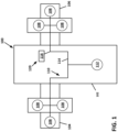
- An aircraft 100 includes a fuselage 102 defining a cabin sized to carry a pilot and one or more passengers.
- the aircraft 100 also includes a first wing 104 and a second wing 106 that each carry one or more propeller arrangements 108 or other propulsion components.
- three propeller arrangements 108 are disposed at each wing 104, 106.
- each wing 104, 106 may carry any desired number or propulsion components.
- each propeller arrangement 108 includes a propeller, a motor, and an inverter to operate the propeller arrangement 108. Other configurations are possible.
- the aircraft 100 includes a power system 110 including at least one battery 112 that powers the propeller arrangements 108 via a power bus 114.
- the propeller arrangements 108 are powered by a main battery 112 carried by the fuselage 102.
- the propeller arrangements 108 may be powered by one or more batteries 112 carried by the wings 104, 106.
- the power system 110 also provides electric power to other components of the aircraft such as the flight management system, the control display unit, and/or lighting.
- the power system 110 also provides electric power to one or more components 116 (e.g., a compressor, a pump, etc.) of a thermal management system 120 used to cool the battery 112 and/or other components such as the propeller arrangement 108.
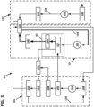
- FIG. 2 illustrates an example thermal management system 120 including one or more cooling circuits 122, 124, 126, 128 that cool various components of the aircraft 100.
- the thermal management system 120 includes a battery cooling circuit 122 configured to cool one or more batteries 112 of the power system 110, a first propeller arrangement cooling circuit 126 configured to cool one or more of the propeller arrangements 108, and a refrigeration circuit 124 configured to cool one or more of the cooling circuits 122, 126.
- a battery cooling circuit 122 configured to cool one or more batteries 112 of the power system 110
- a first propeller arrangement cooling circuit 126 configured to cool one or more of the propeller arrangements 108
- a refrigeration circuit 124 configured to cool one or more of the cooling circuits 122, 126.
- only one propeller arrangement 108 and corresponding cooling circuit 126 is shown. It will be understood however, that the same cooling circuit 126 may service multiple propeller arrangements 108.
- each propeller arrangement 108 may have a respective battery 112 and battery cooling circuit 122.
- the refrigeration circuit 124 includes a conduit 138 through which the refrigerant (e.g., a Hydrofluorocarbon such as R-134a or R410A or other refrigerant) is carried through the refrigeration circuit 124.
- the refrigeration circuit 124 also includes a compressor 140 configured to draw the refrigerant along the conduit 138 and to pressurize (e.g., vaporize) the refrigerant; a condenser arrangement 143 at which heat is removed from the pressurized refrigerant; and an expansion valve 146 at which a pressure drop is created so that low temperature, low pressure refrigerant is then conveyed to the chiller 136.
- the refrigerant e.g., a Hydrofluorocarbon such as R-134a or R410A or other refrigerant
- the refrigeration circuit 124 also includes a compressor 140 configured to draw the refrigerant along the conduit 138 and to pressurize (e.g., vaporize) the refrigerant; a condenser
- the condenser arrangement 143 includes a liquid-cooled condenser 142 at which at least some heat is removed from the pressurized refrigerant; and an air-cooled condenser 144 at which additional heat is removed from the pressurized refrigerant.
- the refrigeration circuit 124 circulates the refrigerant through the liquid-cooled condenser 142 before circulating the refrigerant through the air-cooled condenser 144 (e.g., see FIG. 3 ). In other implementations, however, the refrigerant may be circulated through the air-cooled condenser 144 first.
- the air-cooled condenser 144 is exposed to ambient air outside the aircraft 100 or air routed from outside the aircraft to the air-cooled condenser 144.
- the battery cooling circuit 122 includes a tank 130 configured to hold coolant (e.g., water, propylene glycol, ethylene glycol, or other antifreeze solution), a pump 132 configured to draw the coolant from the tank 130, and a conduit 134 along which the coolant flows through the battery cooling circuit 122.
- coolant e.g., water, propylene glycol, ethylene glycol, or other antifreeze solution
- the conduit 134 is directed from the pump 132 towards the battery 112.
- the coolant After absorbing heat from the battery 112, the coolant is directed to a chiller 136 at which heat is rejected from the coolant to the refrigerant passing through the refrigeration circuit 124.
- the cooled coolant then passes back to the tank 130 (e.g., see FIG. 4 ).
- the propeller arrangement cooling circuit 126 includes a conduit 128 through which coolant flows through the circuit 126.
- the propeller arrangement cooling circuits 126 also includes a tank 148, a pump arrangement 150 of one or more pumps to draw coolant from the tank 148 and circulate the coolant through the conduit 128, and a radiator arrangement 152 exposed to ambient air outside the aircraft.
- the coolant passes from the pump arrangement 150 to a motor and/or an inverter of one or more of the propeller arrangements 108 from which heat is absorbed by the coolant.
- the heated coolant is air cooled at the radiator 152 before returning to the tank 148 (e.g., see FIG. 4 ).
- the radiator arrangement 152 includes one or more radiators.
- a flow control valve 151 directs coolant flow to the one or more of the radiators.
- the flow control valve 151 may control how much coolant flows to each radiator.
- the radiator arrangement 152 includes a radiator for each propeller arrangement 108.
- the radiator arrangement 152 includes three radiators 152a, 152b, 152c.
- the radiator arrangement 152 may includes a greater or lesser number of radiators.
- the radiator arrangement 152 includes all of the radiators disposed on a wing 104, 106 of the aircraft 100.
- the radiator arrangement 152 includes all of the radiators disposed on both wings 104, 106 (e.g., by fluidly combining propeller arrangement cooling circuits 126 of both wings 104, 106).
- the liquid-cooled condenser 142 is cooled by the coolant circulated by the pump 150 of the propeller arrangement cooling circuit 126.
- the propeller arrangement cooling circuit 126 includes a condenser routing path 141 leading past the liquid-cooled condenser 142 of the refrigeration circuit 124. Coolant routed along the condenser routing path 141 cools the vaporized refrigerant within the condenser 142.
- the condenser routing path 141 extends to the liquid-cooled condenser 142 from a location upstream of the propeller arrangement 108 (e.g., see FIG. 4 ).
- a first valve arrangement 109 e.g. a directional control valve
- the first valve arrangement 109 may direct a first portion (e.g., some, all, or none) of the coolant drawn from the tank 148 to the propeller arrangement 108 (e.g., see FIG. 4 ).
- the first valve arrangement 109 also may direct a second portion (e.g., some, all, or none) of the coolant drawn from the tank 148 along the condenser routing path 141 to the liquid-cooled condenser 142 (e.g., see FIGS. 6 and 7 ).
- the first portion is larger than the second portion.
- the first valve arrangement 109 selectively closes the condenser routing path 141 and directs all of the coolant to the propeller arrangement 108 (e.g., see FIG. 4 ).
- the cooled coolant flowing from the radiator arrangement 152 may be further cooled by the refrigeration circuit 124.
- a downstream valve arrangement 154 is disposed downstream of the radiator arrangement 152.
- a first return path 160 extends from the downstream valve arrangement 154 to the tank 148 of the propeller arrangement cooling circuit 126.
- a second return path 162 extends from the downstream valve arrangement 154 to the chiller 136 and then back to the tank 148.
- the downstream valve arrangement 154 is configured to selectively direct the coolant from the radiator arrangement 152 along the first return path 160 and/or along the second return path 162.
- the radiator arrangement 152 is able to provide sufficient cooling to accommodate the heat load from both the propeller arrangement 108 and the liquid-cooled condenser 142. In such cases, the downstream valve arrangement 154 may direct all of the coolant from the radiator 152 back to the tank 148.
- the ambient temperature Tamb is above a threshold T2 (e.g., 25 degrees Celsius, 30 degrees Celsius, 35 degrees Celsius, etc.)
- the downstream valve arrangement 154 may direct all of the coolant from the radiator 152 to pass through the chiller 136.
- the downstream valve arrangement 154 may direct a portion of the coolant from the radiator 152 to the tank 148 and another portion of the coolant to the chiller 136 for additional cooling before being returned to the tank 148.
- some or all of the coolant may be directed to the chiller 136 for cooling regardless of the ambient temperature.
- each of the coolant circuits 122, 126 operates independently.
- the battery cooling circuit 122 has a first coolant that circulates around the battery cooling circuit 122 including along a first path through the chiller 136 while the propeller arrangement cooling circuit 126 has a second coolant that circulates around the propeller arrangement cooling circuit 126 including along a separate, second path through the chiller 136 (e.g., see FIG. 2 ).
- one or more of the coolant circuits 122, 126 may be fluidly coupled together by a return valve 164 (e.g., a directional control valve).
- the coolant circuits 122, 126 may be fluidly coupled during a failure of one or more components of one of the coolant circuits or during a period where one or more components of the power system 110 require extra cooling.
- the first coolant of the battery arrangement cooling circuit 122 is combined with the second coolant of the propeller arrangement cooling circuit 126 prior to passing through the chiller 136 (e.g., see FIG. 8 ). The combined fluid may pass along a common pathway through the chiller 136.
- the combined coolant may be directed to the return valve 164, which directs some of the coolant along a battery circuit return path 164 towards the tank 130 of the battery cooling circuit 122 and other of the coolant along a propeller circuit return path 166 towards the tank 148 of the propeller arrangement cooling circuit 126.
- FIG. 9 illustrates an alternative configuration of the thermal management system 120 in which coolant is routed to the liquid-cooled condenser 142 after being routed past the propeller arrangement 108.
- the coolant absorbs heat from the propeller arrangement 108 and from the liquid-cooled condenser 142 before being routed to the radiator arrangement 152.
- a valve arrangement 145 may be disposed downstream of the propeller arrangement 108 and upstream of the radiator arrangement 152.
- the valve arrangement 145 e.g., a directional control valve
- the heated coolant is routed toward the radiator arrangement 152.
- the thermal management system 120 does not include a valve arrangement 145 and instead directs all heated coolant from the propeller arrangement 108 to the liquid-cooled condenser 142.
- routing the coolant to both the propeller arrangement 108 and the liquid-cooled condenser 142 allows a greater level of fluid flow past these components.
- the coolant directed to both the propeller arrangement 108 and the liquid-cooled condenser 142 is cooled at both the radiator arrangement 152 and the chiller 136 (e.g., see the second return path 162 of FIGS. 7 and 8 ).
- an electronic controller 170 manages operation of various components of the thermal management system 120.
- the electronic controller 170 includes a memory storing operation instructions and a processor configured to implement the operation instructions.
- the electronic controller 170 manages operation of the pumps 132, 150 of the coolant circuits 122, 126 and the compressor 140 of the refrigeration circuit 124 via control lines 172.
- the electronic controller 170 manages operation of the various valves 109, 151, 154, 164, 145 (e.g., directional control valves, flow control valves, etc.) to direct coolant flow through the thermal management system 120 via control lines 174.
- the electronic controller 170 manages operation of one or more temperature sensors T via control lines 176.
- the temperature sensors T are configured to measure temperatures (or other properties from which temperature may be derived) along the coolant flow paths of the cooling circuits 122, 126, at various power components (e.g., the battery 112, the propeller arrangement 108, etc.), and/or outside the aircraft (e.g., to determine an ambient temperature).
- Representative control lines 172, 174, 176 are shown in FIG. 10 .
- the various powered components of the aircraft 100 draw power generally consistently except during certain high power events (e.g., take-off, landing, hovering, turning, etc.).
- One or more powered components e.g., one or more propeller arrangements 108, the battery 112, etc.
- the electronic controller 170 may monitor temperatures of various components (e.g., the battery 112, the first condenser 142, the propeller arrangement 108, etc.) and may adjust the coolant flow through the thermal management system 120 as needed.
- the electronic controller 170 may connect and disconnect the coolant circuits 122, 126 as needed to provide more or less cooling to select components.
- the electronic controller 170 also may increase or decrease an amount of coolant flow along the battery cooling circuit 122 and/or along the propeller arrangement cooling circuit 126 (e.g., by speeding up or slowing down the pumps 132, 150). Similarly, the electronic controller 170 also may increase or decrease the refrigerant flow along the refrigeration circuit 124 (e.g., by speeding up or slowing down the compressor 132).
- FIG. 11 is a flow chart illustrating an example process 200 by which the electronic controller 170 manages the thermal management system 120 during a flight.
- the process 200 includes a determine operation 202 at which a battery cooling load BCL for the battery 112 is determined.
- the electronic controller 170 may measure a temperature of the battery 112.
- the process 200 determines whether the cooling load BCL of the battery 112 exceeds a predetermined threshold Bmax that is set based on a maximum temperature for which the battery 112 is rated.
- the threshold Bmax is set at the maximum temperature for which the battery 112 is rated.
- the threshold Bmax is set a few (e.g., 1, 2, 3, 4, or 5) degrees below the maximum temperature for which the battery 112 is rated.
- the process 200 determines whether the ambient temperature Tamb is above a predetermined threshold Tmax.
- the threshold Tmax is set based on a temperature at which the air-cooled condenser 144 provides inadequate cooling to the coolant.
- the threshold Tmax may be 45 degrees Celsius, 50 degrees Celsius, 55 degrees Celsius, 60 degrees Celsius, etc.).
- the threshold Tmax is set based on a temperature at which the radiator 152 provides inadequate cooling to the propeller arrangement 108 during normal operation.
- the threshold Tmax may be 25 degrees Celsius, 30 degrees Celsius, 35 degrees Celsius, etc.).
- the process 200 determines whether the ambient temperature is not too warm at module 208. If the process 200 determines the ambient temperature is not too warm at module 208, then the process 200 proceeds to a third module 210 at which the process 200 determines whether the battery cooling load BCL is below another threshold Tmin that is set based on a minimum temperature for which the battery 112 is rated.
- the threshold Bmin is set at the minimum temperature for which the battery 112 is rated. In another example, the threshold Bmin is set a few (e.g., 1, 2, 3, 4, or 5) degrees above the minimum temperature for which the battery 112 is rated.
- the process 200 determines whether the ambient temperature Tamb is below a predetermined threshold Tmin. In an example, the threshold Tmin is set based on a temperature at which the air-cooled condenser 144 cools the coolant below the Bmin temperature threshold.
- the process 200 determines the battery cooling load BCL is within the thresholds Bmax and Bmin and determines the ambient temperature is within the temperature thresholds Tmax and Tmin, then the process 200 proceeds a set 214 of operations at which the electronic controller 170 operates the coolant circuits 122, 126 and the refrigerant circuit 124 in a normal state.
- the operation set 214 includes a first operation 216 at which a percentage of coolant flow the valve 109 directs to the first condenser 142 is determined and set. In certain examples, the percentage of coolant flow is determined to be zero and the condenser routing path 141 is closed.
- the operation set 214 also includes a second operation 218 at which a speed of the compressor 140 is determined and set to provide sufficient cooling to the coolant of the battery cooling circuit 122.
- the operation set 214 includes a third operation 220 at which a speed of the battery pump 132 is determined and set to provide adequate coolant flow past the battery 112 to sufficiently cool the battery 112 (e.g., to maintain a battery temperature between 20 and 30 degrees Celsius, between 15 and 35 degrees Celsius, between 22 and 28 degrees Celsius, between 10 and 40 degrees Celsius, etc.).
- the process 200 proceeds to a first adjustment set 222 of operations at which the electronic controller 170 modifies operation of the refrigerant circuit 124, the battery cooling circuit 122, and/or the propeller arrangement cooling circuit 126 to increase the level of cooling provided to the battery 112.
- the first adjustment set 222 of operations includes a first increase operation 224 at which the percentage flow of coolant directed to the liquid-cooled condenser 142 is increased.
- the electronic controller 170 may actuate the valve 109 to begin directing coolant flow (or to increase coolant flow) to the liquid-cooled condenser 142.
- the electronic controller 170 may increase a speed of the pump 150 to increase the flow rate past the liquid-cooled condenser 142.
- Increasing the flow of coolant to the liquid-cooled condenser will increase the amount of cooling of the refrigerant at the liquid-cooled condenser 142 and hence enhance the efficiency of the refrigerant circuit 124.
- the liquid-cooled condenser 142 may supplement cooling the refrigerant when a warm ambient temperature Tamb mitigates the amount of cooling provided by the air-cooled condenser 144.
- the first adjust set 222 of operations also may include fluidly connecting the propeller arrangement cooling circuit 126 to the battery cooling circuit 122 to enhance the level of cooling provided to the liquid-cooled condenser 142.
- the electronic controller 170 may actuate the downstream valve arrangement 154 to fluidly couple the first coolant and the second coolant. Accordingly, the coolant cooling the liquid-cooled condenser 142 would be cooled both by the radiator 152 of the propeller arrangement cooling circuit 126 and also by the refrigeration circuit 124 at the chiller 136 of the battery cooling circuit 122.
- the first adjustment set 222 of operations includes a second increase operation 226 at which the flow of refrigerant through the refrigeration circuit 124 is increased.
- the electronic controller 170 may increase a speed of the compressor 140.
- the first adjustment set 222 of operations includes a third increase operation 228 at which a coolant flow through the battery cooling circuit 122 is increased.
- the electronic controller 170 may increase the speed of the battery pump 132. The process 200 returns to the determine operation 202 to check the temperatures again.
- the process 200 proceeds to a second adjustment set 230 of operations at which the electronic controller 170 modifies operation of the refrigerant circuit 124, the battery cooling circuit 122, and/or the propeller arrangement cooling circuit 126 to decrease the level of cooling provided to the battery 112 and/or to the propeller arrangement 108.
- the second adjustment set 230 of operations includes a first decrease operation 232 at which the percentage flow of coolant directed to the liquid-cooled condenser 142 is decreased.
- the electronic controller 170 may actuate the valve 109 to reduce the amount of coolant directed to the liquid-cooled condenser 142.
- the electronic controller 170 may actuate the valve 109 to close the condenser routing path 141 to cease coolant flow to the liquid-cooled condenser 142. In such examples, the refrigerant would rely on air cooling by the condenser 144.
- the second adjustment set 230 of operations includes a second decrease operation 234 at which the flow of refrigerant through the refrigeration circuit 124 is decreased.
- the electronic controller 170 may decrease a speed of the compressor 140.
- the second adjustment set 230 of operations includes a third decrease operation 236 at which a coolant flow through the battery cooling circuit 122 is decreased.
- the electronic controller 170 may decrease the speed of the battery pump 132. The process 200 returns to the determine operation 202 to check the temperatures again.
Landscapes
- Engineering & Computer Science (AREA)
- Aviation & Aerospace Engineering (AREA)
- Mechanical Engineering (AREA)
- Chemical & Material Sciences (AREA)
- Electrochemistry (AREA)
- Manufacturing & Machinery (AREA)
- Chemical Kinetics & Catalysis (AREA)
- General Chemical & Material Sciences (AREA)
- Thermal Sciences (AREA)
- Physics & Mathematics (AREA)
- Combustion & Propulsion (AREA)
- General Engineering & Computer Science (AREA)
- Automation & Control Theory (AREA)
- Cooling, Air Intake And Gas Exhaust, And Fuel Tank Arrangements In Propulsion Units (AREA)
- Electric Propulsion And Braking For Vehicles (AREA)
Claims (15)
- Wärmesteuerungssystem für ein Flugzeug (100), das eine Propelleranordnung (108) und eine Batterie (112), die die Propelleranordnung mit Strom versorgt einschließt, wobei das Wärmesteuerungssystem (120) Folgendes umfasst:einen Kühlkreislauf (124), der einen Kompressor (140), eine Kondensatoranordnung (143), ein Expansionsventil (146) und einen Kühler (136) einschließt, wobei der Kompressor so konfiguriert ist, dass er ein Kühlmittel an der Kondensatoranordnung und am Expansionsventil vorbei zum Kühler leitet, wobei die Kondensatoranordnung einen luftgekühlten Kondensator (144), der außerhalb des Flugzeugs der Umgebungsluft ausgesetzt ist, und einen flüssigkeitsgekühlten Kondensator (142) einschließt;einen Batteriekühlkreislauf (122), der so konfiguriert ist, dass er das erste Kühlmittel an der Batterie des Flugzeugs vorbeiführt, wobei der Batteriekühlkreislauf einen ersten Tank (130), eine erste Pumpe (132) und den Kühler einschließt, wobei die erste Pumpe so konfiguriert ist, dass sie das erste Kühlmittel vom ersten Tank an der Batterie vorbei, an der Wärme durch das erste Kühlmittel absorbiert wird, zum Kühler leitet, an dem Wärme vom ersten Kühlmittel an das Kühlmittel abgegeben wird; undeinen Kühlkreislauf der Propelleranordnung (126), der so konfiguriert ist, dass er die Propelleranordnung des Flugzeugs unter Verwendung eines zweiten Kühlmittels kühlt, das von einer zweiten Pumpe (150) aus einem zweiten Tank (148) angesaugt wird, wobei der Kühlkreislauf für die Propelleranordnung eine Kühleranordnung (152) einschließt, die der Luft mit Umgebungstemperatur ausgesetzt ist,wobei der Kühlkreislauf der Propelleranordnung (126) so konfiguriert ist, dass das zweite Kühlmittel, das aus dem zweiten Tank angesaugt wird, zur Propelleranordnung und/oder entlang eines Kondensator-Leitpfads (141) zum flüssigkeitsgekühlten Kondensator geleitet wird und die Kühleranordnung stromabwärts des flüssigkeitsgekühlten Kondensators angeordnet ist.
- Wärmesteuerungssystem nach Anspruch 1, ferner umfassend ein stromaufwärts der Propelleranordnung (108) angeordnetes Richtungssteuerventil (109), einen Propeller-Leitpfad von dem Richtungssteuerventil zu der Propelleranordnung und den Kondensator-Leitpfad (141) von dem Richtungssteuerventil zum flüssigkeitsgekühlten Kondensator (142), wobei das Richtungssteuerventil festlegt, wie viel des zweiten Kühlmittels entlang des Propeller- und Kondensator-Leitpfads geleitet wird.
- Wärmesteuerungssystem nach Anspruch 2, wobei das Richtungssteuerventil (109) so konfiguriert ist, dass es das gesamte zweite Kühlmittel entlang eines ersten Strömungspfads leitet.
- Wärmesteuerungssystem nach Anspruch 2, wobei das Richtungssteuerventil (109) so konfiguriert ist, dass es einen ersten Teil des zweiten Kühlmittels entlang des Propeller-Leitpfads leitet und einen zweiten Teil des zweiten Kühlmittels entlang des Kondensator-Leitpfads (141) leitet.
- Wärmesteuerungssystem nach Anspruch 1, wobei die Kühleranordnung (152) eine Vielzahl von Kühlern (152a, 152b, 152c) einschließt, die jeweils der Umgebungstemperaturluft außerhalb des Flugzeugs (100) ausgesetzt sind.
- Wärmesteuerungssystem nach Anspruch 5, weiter umfassend ein Flussregelventil (151), das stromaufwärts der Kühleranordnung (152) angeordnet ist, wobei das Flussregelventil eine Menge des zweiten Kühlmittels steuert, das zu jedem der Vielzahl von Kühlern (152a, 152b, 152c) geleitet wird.
- Wärmesteuerungssystem nach Anspruch 5, wobei alle Kühler (152a, 152b, 152c) von einem Flügel (194, 106) des Flugzeugs (100) getragen werden.
- Wärmesteuerungssystem nach Anspruch 1, ferner umfassend:eine Ventilanordnung (145), die stromaufwärts der Kühleranordnung (152) und stromabwärts der Propelleranordnung (108) angeordnet ist;einen ersten Strömungspfad, der sich von der Ventilanordnung zum flüssigkeitsgekühlten Kondensator (142) erstreckt; undein zweiter Strömungspfad, der sich von der Ventilanordnung zur Kühleranordnung erstreckt;wobei die Ventilanordnung so konfiguriert ist, dass sie das zweite Kühlmittel entlang des ersten Strömungspfads und/oder entlang des zweiten Strömungspfads leitet.
- Wärmesteuerungssystem nach Anspruch 1, ferner umfassend:eine stromabwärts gelegene Ventilanordnung (154), die stromabwärts der Kühleranordnung (152) angeordnet ist;einen ersten Rücklaufpfad (160), der sich von der stromabwärts gelegenen Ventilanordnung zum zweiten Tank (148) des Kühlkreislaufs der Propelleranordnung erstreckt (126); undeinen zweiten Rücklaufpfad (162), der sich von der stromabwärts gelegenen Ventilanordnung zum Kühler (136) erstreckt;wobei die stromabwärts gelegene Ventilanordnung so konfiguriert ist, dass sie das zweite Kühlmittel von der Kühleranordnung entlang des ersten Rücklaufpfads und/oder entlang des zweiten Rücklaufpfads leitet.
- Wärmesteuerungssystem nach Anspruch 1, ferner umfassend:ein Rücklaufventil (164), das stromaufwärts des Kühlers (136) angeordnet ist;ein Batteriekreislauf-Rücklaufpfad, der sich vom Rücklaufventil zum ersten Tank (130) des Batteriekühlkreislaufs (122) erstreckt; undeinen Propellerkreislauf-Rücklaufpfad (166), der sich vom Rücklaufventil zum zweiten Tank (148) des Kühlkreislaufs der Propelleranordnung (126) erstreckt;wobei das Rücklaufventil so konfiguriert ist, dass es eine Kombination aus erstem und zweitem Kühlmittel aus dem Kühler aufnimmt und einen Teil der Kombination entlang des Batteriekreislauf-Rücklaufpfads und einen weiteren Teil der Kombination entlang des Propellerkreislauf-Rücklaufpfads leitet.
- Wärmesteuerungssystem nach Anspruch 1, wobei das erste Kühlmittel entlang eines ersten Pfads durch den Kühler (136) fließt und das zweite Kühlmittel entlang eines zweiten Pfads durch den Kühler fließt, der separat vom ersten Pfad ist, wobei sowohl der erste als auch der zweite Pfad relativ zu einem Kühlmittelpfad durch den Kühler angeordnet sind, um eine Wärmeabgabe vom ersten und zweiten Pfad an den Kühlmittelpfad zu ermöglichen.
- Verfahren zum Kühlen einer Propelleranordnung (108) eines Flugzeugs (100), wobei das Verfahren Folgendes umfasst:Leiten eines ersten Teils des Kühlmittels von einem Tank (148) zu der Propelleranordnung unter Verwendung einer Pumpenanordnung (150), so dass das Kühlmittel Wärme von der Propelleranordnung absorbiert;Leiten des erwärmten ersten Teils des Kühlmittels von der Propelleranordnung zu einer Kühleranordnung (152), an der der erwärmte erste Teil des Kühlmittels durch Umgebungsluft außerhalb des Flugzeugs gekühlt wird;Leiten eines zweiten Teils des Kühlmittels vom Tank zu einem flüssigkeitsgekühlten Kondensator (142) eines Kühlkreislaufs (124), an dem Wärme vom Kühlmittel an den zweiten Teil des Kühlmittels abgegeben wird; undLeiten des erwärmten zweiten Teils des Kühlmittels vom flüssigkeitsgekühlten Kondensator zur Kühleranordnung, an der der erwärmte zweite Teil des Kühlmittels durch Umgebungsluft außerhalb des Flugzeugs gekühlt wird.
- Verfahren nach Anspruch 12, ferner umfassend:
Leiten des Kühlmittels entlang des Kühlkreislaufs (124) unter Verwendung eines Kompressors (140), wobei der Kühlkreislauf auch einen luftgekühlten Kondensator (144) und einen Kühler (136) einschließt, wobei das Kühlmittel ein erstes Kühlmittel ist; und wobei das Verfahren ferner das Leiten eines zweiten Kühlmittels an einer Batterie (112) des Flugzeugs vorbei und dann am Kühler vorbei umfasst, um Wärme an das Kühlmittel abzugeben. - Verfahren nach Anspruch 12, ferner umfassend:Bestimmen, dass eine Umgebungstemperatur der Luft außerhalb des Flugzeugs (100) über einem ersten Schwellenwert liegt;Erhöhen des Stroms des zweiten Teils des Kühlmittels zum flüssigkeitsgekühlten Kondensator (142) als Reaktion auf das Bestimmen; undErhöhen der Strömungsrate des Kühlmittels im Kühlkreislauf (124).
- Verfahren nach Anspruch 12, ferner umfassend:Bestimmen, dass eine Umgebungstemperatur der Luft außerhalb des Flugzeugs (100) unter einem zweiten Schwellenwert liegt;Verringern des Stroms des zweiten Teils des Kühlmittels zum flüssigkeitsgekühlten Kondensator (142) als Reaktion auf das Bestimmen; undVerringern der Strömungsrate des Kühlmittels im Kühlkreislauf (124).
Applications Claiming Priority (1)
| Application Number | Priority Date | Filing Date | Title |
|---|---|---|---|
| IN202111041292 | 2021-09-14 |
Publications (2)
| Publication Number | Publication Date |
|---|---|
| EP4147977A1 EP4147977A1 (de) | 2023-03-15 |
| EP4147977B1 true EP4147977B1 (de) | 2025-05-21 |
Family
ID=83318927
Family Applications (1)
| Application Number | Title | Priority Date | Filing Date |
|---|---|---|---|
| EP22195471.2A Active EP4147977B1 (de) | 2021-09-14 | 2022-09-13 | Wärmesteuerungssystem mit doppel-kondensatoren |
Country Status (2)
| Country | Link |
|---|---|
| US (2) | US12220965B2 (de) |
| EP (1) | EP4147977B1 (de) |
Families Citing this family (3)
| Publication number | Priority date | Publication date | Assignee | Title |
|---|---|---|---|---|
| US12240620B2 (en) | 2021-08-31 | 2025-03-04 | Eaton Intelligent Power Limited | Thermal management system |
| EP4147977B1 (de) * | 2021-09-14 | 2025-05-21 | Eaton Intelligent Power Limited | Wärmesteuerungssystem mit doppel-kondensatoren |
| CN116505136B (zh) * | 2023-06-25 | 2024-03-19 | 宁德时代新能源科技股份有限公司 | 热管理控制方法、装置、设备及存储介质 |
Family Cites Families (39)
| Publication number | Priority date | Publication date | Assignee | Title |
|---|---|---|---|---|
| US8448460B2 (en) | 2008-06-23 | 2013-05-28 | GM Global Technology Operations LLC | Vehicular combination chiller bypass system and method |
| DE102008062176A1 (de) * | 2008-12-13 | 2010-06-17 | Modine Manufacturing Co., Racine | Einrichtung und Verfahren zum Temperieren von elektrischen Elementen |
| DE102010042122B4 (de) * | 2010-10-07 | 2019-02-28 | Audi Ag | Kühlvorrichtung eines Fahrzeuges |
| US9669936B1 (en) * | 2012-10-24 | 2017-06-06 | The Boeing Company | Aircraft air conditioning systems and methods |
| KR101628120B1 (ko) | 2014-10-20 | 2016-06-08 | 현대자동차 주식회사 | 차량용 배터리 냉각 시스템 |
| US9780422B2 (en) | 2015-05-20 | 2017-10-03 | Ford Global Technologies, Llc | Cabin and battery cooling control for electrified vehicles |
| US10076944B2 (en) | 2016-01-29 | 2018-09-18 | Ford Global Technologies, Llc | Vehicle cabin air conditioning and battery cooling system |
| DE102016112095A1 (de) * | 2016-07-01 | 2018-01-04 | Hanon Systems | System zum Klimatisieren der Luft eines Fahrgastraums und zur Wärmeübertragung mit Antriebskomponenten eines Kraftfahrzeugs sowie Verfahren zum Betreiben des Systems |
| US10644367B2 (en) | 2016-10-04 | 2020-05-05 | Ford Global Technologies, Llc | Electric vehicle battery cooling using excess cabin air conditioning capacity |
| DE102016219680A1 (de) | 2016-10-11 | 2018-04-12 | Siemens Aktiengesellschaft | Antriebssystem für ein Fahrzeug mit Verbrennungskraftmaschine und Treibstofftank |
| US11046448B2 (en) | 2016-12-20 | 2021-06-29 | Textron Innovations Inc. | Engine cooling systems for aircraft |
| US10513982B2 (en) | 2017-02-22 | 2019-12-24 | Textron Innovations Inc. | Rotorcraft having increased altitude density ceiling |
| JP6690885B2 (ja) | 2017-02-27 | 2020-04-28 | 東芝三菱電機産業システム株式会社 | 制御装置 |
| US20200361304A1 (en) | 2017-08-21 | 2020-11-19 | Sony Corporation | Motor device and motor-driven type moving body |
| US10696412B2 (en) | 2017-09-29 | 2020-06-30 | The Boeing Company | Combined fluid ice protection and electronic cooling system |
| KR102391004B1 (ko) | 2017-10-31 | 2022-04-27 | 현대자동차주식회사 | 워터 펌프 제어 방법 및 시스템 |
| GB201718141D0 (en) * | 2017-11-02 | 2017-12-20 | Rolls Royce Plc | Thermal management system |
| US11289756B2 (en) | 2018-05-18 | 2022-03-29 | The Johns Hopkins University | Active thermal management of battery cells via thermoelectrics |
| DE102018113687B4 (de) | 2018-06-08 | 2023-08-03 | Hanon Systems | Vorrichtung und Verfahren zur Kühlung von Batteriezellenmodulen |
| KR102575995B1 (ko) | 2018-10-04 | 2023-09-08 | 한온시스템 주식회사 | 열관리 시스템 |
| DE102019107191A1 (de) * | 2019-03-20 | 2020-09-24 | Bayerische Motoren Werke Aktiengesellschaft | Wärmesystem für ein Elektro- oder Hybridfahrzeug, Elektro- oder Hybridfahrzeug, Verfahren zum Betrieb eines Wärmesystems |
| US11466621B2 (en) | 2019-03-20 | 2022-10-11 | Raytheon Technologies Corporation | Adaptive thermal management system for aircraft fuel system |
| US11152653B2 (en) | 2019-04-23 | 2021-10-19 | GM Global Technology Operations LLC | Battery thermal management |
| EP3959770B1 (de) | 2019-04-23 | 2025-04-23 | Joby Aero, Inc. | Wärmeverwaltungssystem und -verfahren für batterie |
| US11230384B2 (en) | 2019-04-23 | 2022-01-25 | Joby Aero, Inc. | Vehicle cabin thermal management system and method |
| WO2020242899A1 (en) | 2019-05-24 | 2020-12-03 | Alakai Technologies Corporation | Integrated multimode thermal energy transfer system, method and apparatus for clean fuel electric multirotor aircraft |
| US20210061477A1 (en) | 2019-08-30 | 2021-03-04 | Bell Textron Inc. | Cabin thermal management system |
| JP7185069B2 (ja) | 2019-11-12 | 2022-12-06 | 株式会社Subaru | 推進装置、ロータの防氷方法及び航空機 |
| CN110758056B (zh) * | 2019-11-25 | 2021-07-09 | 西安交通大学 | 一种混合动力汽车的整车热管理系统与方法 |
| CN111591108A (zh) | 2020-06-28 | 2020-08-28 | 南方英特空调有限公司 | 结合电池冷却器与电机余热的汽车热泵采暖系统及方法 |
| CN213383775U (zh) | 2020-08-17 | 2021-06-08 | 南方英特空调有限公司 | 一种汽车空调热泵系统 |
| US11909019B2 (en) | 2021-02-19 | 2024-02-20 | Transportation Ip Holdings, Llc | Battery management system |
| WO2022184325A1 (en) | 2021-03-05 | 2022-09-09 | Eaton Intelligent Power Limited | System and method for generating electrical energy from thermal waste energy and removing thermal waste energy in an aircraft |
| US12054266B2 (en) * | 2021-03-29 | 2024-08-06 | Aurora Flight Sciences Corporation | Integrated electric nacelle system and method |
| EP4141609B1 (de) | 2021-08-31 | 2026-02-11 | Eaton Intelligent Power Limited | Proaktives wärmeverwaltungssystem |
| US12240620B2 (en) * | 2021-08-31 | 2025-03-04 | Eaton Intelligent Power Limited | Thermal management system |
| EP4147977B1 (de) * | 2021-09-14 | 2025-05-21 | Eaton Intelligent Power Limited | Wärmesteuerungssystem mit doppel-kondensatoren |
| US12285991B2 (en) * | 2021-12-28 | 2025-04-29 | Nuro, Inc. | Thermal system for autonomous vehicle |
| US11827370B1 (en) * | 2022-06-21 | 2023-11-28 | Pratt & Whitney Canada Corp. | Aircraft propulsion system with intermittent combustion engine and electric transmission system and method for operating the same |
-
2022
- 2022-09-13 EP EP22195471.2A patent/EP4147977B1/de active Active
- 2022-09-14 US US17/944,438 patent/US12220965B2/en active Active
-
2025
- 2025-02-07 US US19/048,547 patent/US20250178402A1/en active Pending
Also Published As
| Publication number | Publication date |
|---|---|
| US12220965B2 (en) | 2025-02-11 |
| US20230079696A1 (en) | 2023-03-16 |
| US20250178402A1 (en) | 2025-06-05 |
| EP4147977A1 (de) | 2023-03-15 |
Similar Documents
| Publication | Publication Date | Title |
|---|---|---|
| EP4147977B1 (de) | Wärmesteuerungssystem mit doppel-kondensatoren | |
| US12351001B2 (en) | Heat pump assembly with a chiller for battery-powered vehicles and methods of operating the heat pump assembly | |
| US12240620B2 (en) | Thermal management system | |
| EP3621839B1 (de) | Kühlanordnung zur kühlung einer elektrischen maschine und wenigstens eines weiteren bauteils einer elektrischen leistungseinheit und fahrzeug, eine solche kühlanordnung umfassend | |
| US20200298663A1 (en) | Thermal System for an Electric or Hybrid Vehicle, Electric or Hybrid Vehicle, Method for Operating a Thermal System | |
| KR102294593B1 (ko) | 자동차의 열 시스템 및 상기 열 시스템의 작동 방법 | |
| US8448460B2 (en) | Vehicular combination chiller bypass system and method | |
| US8042343B2 (en) | Cooling of avionics using a fuel tank and refrigerant source | |
| EP3123085B1 (de) | Kälteeinrichtung eines fahrzeugs mit flüssigwärmerückweisungssystem | |
| KR20200096866A (ko) | 높은 냉각 용량 및 수동 배터리 냉각을 갖는 에어컨 및 배터리 냉각 장치와 에어컨 및 배터리 냉각 장치의 작동 방법 | |
| US11203247B2 (en) | Thermal regulation system provided with Peltier cell for electric drive vehicles | |
| RU2371356C2 (ru) | Система для охлаждения теплопроизводящих устройств в воздушном судне | |
| EP4141609B1 (de) | Proaktives wärmeverwaltungssystem | |
| US20180020573A1 (en) | Thermal management systems for electronics | |
| US20150128626A1 (en) | Heating, Ventilation And/Or Air-Conditioning Equipment Comprising A Device For Controlling The Temperature Of A Battery, And Method For Implementing Same | |
| US10501191B1 (en) | Integrated aircraft cooling machine | |
| US20240300289A1 (en) | Thermal management system | |
| US9698435B2 (en) | System and method for cooling an aircraft fuel cell system | |
| US20240076043A1 (en) | Moving object | |
| EP3650266A1 (de) | Wärmeregulierungssystem für elektrisch angetriebene fahrzeuge und mit diesem system ausgestattetes, elektrisch angetriebenes fahrzeug | |
| US11807074B2 (en) | Vehicle cabin comfort management system | |
| US12491753B2 (en) | Thermal management system | |
| US11592221B2 (en) | Two-phase cooling system | |
| KR20250145698A (ko) | 자동차, 특히 차량용 온도 제어 장치 및 이와 같은 온도 제어 장치를 갖춘 자동차 |
Legal Events
| Date | Code | Title | Description |
|---|---|---|---|
| PUAI | Public reference made under article 153(3) epc to a published international application that has entered the european phase |
Free format text: ORIGINAL CODE: 0009012 |
|
| STAA | Information on the status of an ep patent application or granted ep patent |
Free format text: STATUS: THE APPLICATION HAS BEEN PUBLISHED |
|
| AK | Designated contracting states |
Kind code of ref document: A1 Designated state(s): AL AT BE BG CH CY CZ DE DK EE ES FI FR GB GR HR HU IE IS IT LI LT LU LV MC MK MT NL NO PL PT RO RS SE SI SK SM TR |
|
| P01 | Opt-out of the competence of the unified patent court (upc) registered |
Effective date: 20230521 |
|
| STAA | Information on the status of an ep patent application or granted ep patent |
Free format text: STATUS: REQUEST FOR EXAMINATION WAS MADE |
|
| 17P | Request for examination filed |
Effective date: 20230914 |
|
| RBV | Designated contracting states (corrected) |
Designated state(s): AL AT BE BG CH CY CZ DE DK EE ES FI FR GB GR HR HU IE IS IT LI LT LU LV MC MK MT NL NO PL PT RO RS SE SI SK SM TR |
|
| REG | Reference to a national code |
Ref country code: DE Ref legal event code: R079 Free format text: PREVIOUS MAIN CLASS: B64D0027040000 Ipc: B64D0027300000 Ref country code: DE Ref legal event code: R079 Ref document number: 602022014898 Country of ref document: DE Free format text: PREVIOUS MAIN CLASS: B64D0027040000 Ipc: B64D0027300000 |
|
| GRAP | Despatch of communication of intention to grant a patent |
Free format text: ORIGINAL CODE: EPIDOSNIGR1 |
|
| STAA | Information on the status of an ep patent application or granted ep patent |
Free format text: STATUS: GRANT OF PATENT IS INTENDED |
|
| RIC1 | Information provided on ipc code assigned before grant |
Ipc: B64D 33/10 20060101ALI20241204BHEP Ipc: B64D 33/08 20060101ALI20241204BHEP Ipc: H02K 9/19 20060101ALI20241204BHEP Ipc: H02K 9/00 20060101ALI20241204BHEP Ipc: H01M 10/62 20140101ALI20241204BHEP Ipc: H01M 10/613 20140101ALI20241204BHEP Ipc: B64D 27/357 20240101ALI20241204BHEP Ipc: B64D 27/30 20240101AFI20241204BHEP |
|
| INTG | Intention to grant announced |
Effective date: 20241213 |
|
| GRAS | Grant fee paid |
Free format text: ORIGINAL CODE: EPIDOSNIGR3 |
|
| GRAA | (expected) grant |
Free format text: ORIGINAL CODE: 0009210 |
|
| STAA | Information on the status of an ep patent application or granted ep patent |
Free format text: STATUS: THE PATENT HAS BEEN GRANTED |
|
| AK | Designated contracting states |
Kind code of ref document: B1 Designated state(s): AL AT BE BG CH CY CZ DE DK EE ES FI FR GB GR HR HU IE IS IT LI LT LU LV MC MK MT NL NO PL PT RO RS SE SI SK SM TR |
|
| REG | Reference to a national code |
Ref country code: GB Ref legal event code: FG4D |
|
| REG | Reference to a national code |
Ref country code: CH Ref legal event code: EP |
|
| REG | Reference to a national code |
Ref country code: DE Ref legal event code: R096 Ref document number: 602022014898 Country of ref document: DE |
|
| REG | Reference to a national code |
Ref country code: IE Ref legal event code: FG4D |
|
| REG | Reference to a national code |
Ref country code: NL Ref legal event code: MP Effective date: 20250521 |
|
| PG25 | Lapsed in a contracting state [announced via postgrant information from national office to epo] |
Ref country code: FI Free format text: LAPSE BECAUSE OF FAILURE TO SUBMIT A TRANSLATION OF THE DESCRIPTION OR TO PAY THE FEE WITHIN THE PRESCRIBED TIME-LIMIT Effective date: 20250521 Ref country code: ES Free format text: LAPSE BECAUSE OF FAILURE TO SUBMIT A TRANSLATION OF THE DESCRIPTION OR TO PAY THE FEE WITHIN THE PRESCRIBED TIME-LIMIT Effective date: 20250521 Ref country code: PT Free format text: LAPSE BECAUSE OF FAILURE TO SUBMIT A TRANSLATION OF THE DESCRIPTION OR TO PAY THE FEE WITHIN THE PRESCRIBED TIME-LIMIT Effective date: 20250922 |
|
| PGFP | Annual fee paid to national office [announced via postgrant information from national office to epo] |
Ref country code: DE Payment date: 20250923 Year of fee payment: 4 |
|
| REG | Reference to a national code |
Ref country code: LT Ref legal event code: MG9D |
|
| PG25 | Lapsed in a contracting state [announced via postgrant information from national office to epo] |
Ref country code: NO Free format text: LAPSE BECAUSE OF FAILURE TO SUBMIT A TRANSLATION OF THE DESCRIPTION OR TO PAY THE FEE WITHIN THE PRESCRIBED TIME-LIMIT Effective date: 20250821 Ref country code: GR Free format text: LAPSE BECAUSE OF FAILURE TO SUBMIT A TRANSLATION OF THE DESCRIPTION OR TO PAY THE FEE WITHIN THE PRESCRIBED TIME-LIMIT Effective date: 20250822 |
|
| PG25 | Lapsed in a contracting state [announced via postgrant information from national office to epo] |
Ref country code: NL Free format text: LAPSE BECAUSE OF FAILURE TO SUBMIT A TRANSLATION OF THE DESCRIPTION OR TO PAY THE FEE WITHIN THE PRESCRIBED TIME-LIMIT Effective date: 20250521 Ref country code: PL Free format text: LAPSE BECAUSE OF FAILURE TO SUBMIT A TRANSLATION OF THE DESCRIPTION OR TO PAY THE FEE WITHIN THE PRESCRIBED TIME-LIMIT Effective date: 20250521 |
|
| PG25 | Lapsed in a contracting state [announced via postgrant information from national office to epo] |
Ref country code: BG Free format text: LAPSE BECAUSE OF FAILURE TO SUBMIT A TRANSLATION OF THE DESCRIPTION OR TO PAY THE FEE WITHIN THE PRESCRIBED TIME-LIMIT Effective date: 20250521 |
|
| PG25 | Lapsed in a contracting state [announced via postgrant information from national office to epo] |
Ref country code: HR Free format text: LAPSE BECAUSE OF FAILURE TO SUBMIT A TRANSLATION OF THE DESCRIPTION OR TO PAY THE FEE WITHIN THE PRESCRIBED TIME-LIMIT Effective date: 20250521 |
|
| PGFP | Annual fee paid to national office [announced via postgrant information from national office to epo] |
Ref country code: FR Payment date: 20250829 Year of fee payment: 4 |
|
| PG25 | Lapsed in a contracting state [announced via postgrant information from national office to epo] |
Ref country code: RS Free format text: LAPSE BECAUSE OF FAILURE TO SUBMIT A TRANSLATION OF THE DESCRIPTION OR TO PAY THE FEE WITHIN THE PRESCRIBED TIME-LIMIT Effective date: 20250821 |
|
| PG25 | Lapsed in a contracting state [announced via postgrant information from national office to epo] |
Ref country code: IS Free format text: LAPSE BECAUSE OF FAILURE TO SUBMIT A TRANSLATION OF THE DESCRIPTION OR TO PAY THE FEE WITHIN THE PRESCRIBED TIME-LIMIT Effective date: 20250921 |
|
| PG25 | Lapsed in a contracting state [announced via postgrant information from national office to epo] |
Ref country code: LV Free format text: LAPSE BECAUSE OF FAILURE TO SUBMIT A TRANSLATION OF THE DESCRIPTION OR TO PAY THE FEE WITHIN THE PRESCRIBED TIME-LIMIT Effective date: 20250521 |
|
| REG | Reference to a national code |
Ref country code: AT Ref legal event code: MK05 Ref document number: 1796557 Country of ref document: AT Kind code of ref document: T Effective date: 20250521 |
|
| PG25 | Lapsed in a contracting state [announced via postgrant information from national office to epo] |
Ref country code: DK Free format text: LAPSE BECAUSE OF FAILURE TO SUBMIT A TRANSLATION OF THE DESCRIPTION OR TO PAY THE FEE WITHIN THE PRESCRIBED TIME-LIMIT Effective date: 20250521 Ref country code: AT Free format text: LAPSE BECAUSE OF FAILURE TO SUBMIT A TRANSLATION OF THE DESCRIPTION OR TO PAY THE FEE WITHIN THE PRESCRIBED TIME-LIMIT Effective date: 20250521 Ref country code: SM Free format text: LAPSE BECAUSE OF FAILURE TO SUBMIT A TRANSLATION OF THE DESCRIPTION OR TO PAY THE FEE WITHIN THE PRESCRIBED TIME-LIMIT Effective date: 20250521 |
|
| PG25 | Lapsed in a contracting state [announced via postgrant information from national office to epo] |
Ref country code: CZ Free format text: LAPSE BECAUSE OF FAILURE TO SUBMIT A TRANSLATION OF THE DESCRIPTION OR TO PAY THE FEE WITHIN THE PRESCRIBED TIME-LIMIT Effective date: 20250521 |
|
| PG25 | Lapsed in a contracting state [announced via postgrant information from national office to epo] |
Ref country code: EE Free format text: LAPSE BECAUSE OF FAILURE TO SUBMIT A TRANSLATION OF THE DESCRIPTION OR TO PAY THE FEE WITHIN THE PRESCRIBED TIME-LIMIT Effective date: 20250521 |
|
| PG25 | Lapsed in a contracting state [announced via postgrant information from national office to epo] |
Ref country code: SK Free format text: LAPSE BECAUSE OF FAILURE TO SUBMIT A TRANSLATION OF THE DESCRIPTION OR TO PAY THE FEE WITHIN THE PRESCRIBED TIME-LIMIT Effective date: 20250521 |
|
| PG25 | Lapsed in a contracting state [announced via postgrant information from national office to epo] |
Ref country code: IT Free format text: LAPSE BECAUSE OF FAILURE TO SUBMIT A TRANSLATION OF THE DESCRIPTION OR TO PAY THE FEE WITHIN THE PRESCRIBED TIME-LIMIT Effective date: 20250521 |
|
| PG25 | Lapsed in a contracting state [announced via postgrant information from national office to epo] |
Ref country code: RO Free format text: LAPSE BECAUSE OF FAILURE TO SUBMIT A TRANSLATION OF THE DESCRIPTION OR TO PAY THE FEE WITHIN THE PRESCRIBED TIME-LIMIT Effective date: 20250521 |