EP4147950A1 - Automotive impact energy absorptive part - Google Patents
Automotive impact energy absorptive part Download PDFInfo
- Publication number
- EP4147950A1 EP4147950A1 EP21824756.7A EP21824756A EP4147950A1 EP 4147950 A1 EP4147950 A1 EP 4147950A1 EP 21824756 A EP21824756 A EP 21824756A EP 4147950 A1 EP4147950 A1 EP 4147950A1
- Authority
- EP
- European Patent Office
- Prior art keywords
- closed cross
- resin
- section space
- automotive
- crashworthiness
- Prior art date
- Legal status (The legal status is an assumption and is not a legal conclusion. Google has not performed a legal analysis and makes no representation as to the accuracy of the status listed.)
- Pending
Links
Images





Classifications
-
- B—PERFORMING OPERATIONS; TRANSPORTING
- B62—LAND VEHICLES FOR TRAVELLING OTHERWISE THAN ON RAILS
- B62D—MOTOR VEHICLES; TRAILERS
- B62D25/00—Superstructure or monocoque structure sub-units; Parts or details thereof not otherwise provided for
- B62D25/04—Door pillars ; windshield pillars
-
- B—PERFORMING OPERATIONS; TRANSPORTING
- B32—LAYERED PRODUCTS
- B32B—LAYERED PRODUCTS, i.e. PRODUCTS BUILT-UP OF STRATA OF FLAT OR NON-FLAT, e.g. CELLULAR OR HONEYCOMB, FORM
- B32B15/00—Layered products comprising a layer of metal
- B32B15/04—Layered products comprising a layer of metal comprising metal as the main or only constituent of a layer, which is next to another layer of the same or of a different material
- B32B15/08—Layered products comprising a layer of metal comprising metal as the main or only constituent of a layer, which is next to another layer of the same or of a different material of synthetic resin
- B32B15/092—Layered products comprising a layer of metal comprising metal as the main or only constituent of a layer, which is next to another layer of the same or of a different material of synthetic resin comprising epoxy resins
-
- B—PERFORMING OPERATIONS; TRANSPORTING
- B62—LAND VEHICLES FOR TRAVELLING OTHERWISE THAN ON RAILS
- B62D—MOTOR VEHICLES; TRAILERS
- B62D21/00—Understructures, i.e. chassis frame on which a vehicle body may be mounted
- B62D21/15—Understructures, i.e. chassis frame on which a vehicle body may be mounted having impact absorbing means, e.g. a frame designed to permanently or temporarily change shape or dimension upon impact with another body
-
- B—PERFORMING OPERATIONS; TRANSPORTING
- B62—LAND VEHICLES FOR TRAVELLING OTHERWISE THAN ON RAILS
- B62D—MOTOR VEHICLES; TRAILERS
- B62D25/00—Superstructure or monocoque structure sub-units; Parts or details thereof not otherwise provided for
-
- B—PERFORMING OPERATIONS; TRANSPORTING
- B62—LAND VEHICLES FOR TRAVELLING OTHERWISE THAN ON RAILS
- B62D—MOTOR VEHICLES; TRAILERS
- B62D25/00—Superstructure or monocoque structure sub-units; Parts or details thereof not otherwise provided for
- B62D25/08—Front or rear portions
-
- B—PERFORMING OPERATIONS; TRANSPORTING
- B62—LAND VEHICLES FOR TRAVELLING OTHERWISE THAN ON RAILS
- B62D—MOTOR VEHICLES; TRAILERS
- B62D29/00—Superstructures, understructures, or sub-units thereof, characterised by the material thereof
- B62D29/001—Superstructures, understructures, or sub-units thereof, characterised by the material thereof characterised by combining metal and synthetic material
- B62D29/004—Superstructures, understructures, or sub-units thereof, characterised by the material thereof characterised by combining metal and synthetic material the metal being over-moulded by the synthetic material, e.g. in a mould
-
- B—PERFORMING OPERATIONS; TRANSPORTING
- B62—LAND VEHICLES FOR TRAVELLING OTHERWISE THAN ON RAILS
- B62D—MOTOR VEHICLES; TRAILERS
- B62D29/00—Superstructures, understructures, or sub-units thereof, characterised by the material thereof
- B62D29/007—Superstructures, understructures, or sub-units thereof, characterised by the material thereof predominantly of special steel or specially treated steel, e.g. stainless steel or locally surface hardened steel
-
- F—MECHANICAL ENGINEERING; LIGHTING; HEATING; WEAPONS; BLASTING
- F16—ENGINEERING ELEMENTS AND UNITS; GENERAL MEASURES FOR PRODUCING AND MAINTAINING EFFECTIVE FUNCTIONING OF MACHINES OR INSTALLATIONS; THERMAL INSULATION IN GENERAL
- F16F—SPRINGS; SHOCK-ABSORBERS; MEANS FOR DAMPING VIBRATION
- F16F7/00—Vibration-dampers; Shock-absorbers
- F16F7/003—One-shot shock absorbers
-
- F—MECHANICAL ENGINEERING; LIGHTING; HEATING; WEAPONS; BLASTING
- F16—ENGINEERING ELEMENTS AND UNITS; GENERAL MEASURES FOR PRODUCING AND MAINTAINING EFFECTIVE FUNCTIONING OF MACHINES OR INSTALLATIONS; THERMAL INSULATION IN GENERAL
- F16F—SPRINGS; SHOCK-ABSORBERS; MEANS FOR DAMPING VIBRATION
- F16F7/00—Vibration-dampers; Shock-absorbers
- F16F7/12—Vibration-dampers; Shock-absorbers using plastic deformation of members
-
- B—PERFORMING OPERATIONS; TRANSPORTING
- B60—VEHICLES IN GENERAL
- B60Y—INDEXING SCHEME RELATING TO ASPECTS CROSS-CUTTING VEHICLE TECHNOLOGY
- B60Y2306/00—Other features of vehicle sub-units
- B60Y2306/01—Reducing damages in case of crash, e.g. by improving battery protection
-
- F—MECHANICAL ENGINEERING; LIGHTING; HEATING; WEAPONS; BLASTING
- F16—ENGINEERING ELEMENTS AND UNITS; GENERAL MEASURES FOR PRODUCING AND MAINTAINING EFFECTIVE FUNCTIONING OF MACHINES OR INSTALLATIONS; THERMAL INSULATION IN GENERAL
- F16F—SPRINGS; SHOCK-ABSORBERS; MEANS FOR DAMPING VIBRATION
- F16F2224/00—Materials; Material properties
- F16F2224/02—Materials; Material properties solids
- F16F2224/025—Elastomers
-
- F—MECHANICAL ENGINEERING; LIGHTING; HEATING; WEAPONS; BLASTING
- F16—ENGINEERING ELEMENTS AND UNITS; GENERAL MEASURES FOR PRODUCING AND MAINTAINING EFFECTIVE FUNCTIONING OF MACHINES OR INSTALLATIONS; THERMAL INSULATION IN GENERAL
- F16F—SPRINGS; SHOCK-ABSORBERS; MEANS FOR DAMPING VIBRATION
- F16F2228/00—Functional characteristics, e.g. variability, frequency-dependence
- F16F2228/001—Specific functional characteristics in numerical form or in the form of equations
- F16F2228/005—Material properties, e.g. moduli
- F16F2228/007—Material properties, e.g. moduli of solids, e.g. hardness
Definitions
- the present invention relates to an automotive crashworthiness energy absorptive part, and more particularly to an automotive crashworthiness energy absorptive part that absorbs crashworthiness energy by crushing axially in a longitudinal direction when a crashworthiness load is input from the front or the rear of an automotive body.
- Patent Literature 1 discloses a technique in which a structural part configured to form a closed space inside by aligning the directions of the top portions and overlapping the flanges of hat-shaped cross section parts such as a side sill, a floor member, and a pillar with each other is filled with a foaming filler to improve the bending strength and torsional stiffness of the structural part with a minimum weight increase, and thereby to improve the rigidity and collision safety of the automotive body.
- Patent Literature 2 discloses a technique in which, when an internal space of a structure with a closed cross section such as a pillar formed by opposing hat-shaped cross section parts to each other and joining the flange portions is filled with a foamed body with high rigidity, the foamed body is fixed by action of the compressive counterforce due to filling and foaming of the foamed body with high rigidity to improve the vibration damping performance for suppressing the transmission of vibration sound while improving the strength, rigidity, and impact energy absorptive properties.
- Patent Literature 1 and Patent Literature 2 by filling the automotive part with the foaming filler or the foamed body, it is possible to improve strength against bending deformation of the automotive part, impact energy absorptive properties against bending deformation due to crash, and furthermore, rigidity against torsional deformation, and thus to suppress the deformation of the automotive part.
- the present invention has been made in view of the above problems, and an object of the present invention is to provide an automotive crashworthiness energy absorptive part capable of improving the crashworthiness energy absorbing effect while the automotive crashworthiness energy absorptive part axially crushes in a bellows-shaped manner when a crashworthiness load is input from the front or the rear of the automotive body such as the front side member or crash box, and capable of ensuring water resistance and thereby stably maintaining an excellent crashworthiness energy absorbing effect without change even when used for a long period of time in the use environment of an actual vehicle such as rainy weather or high humidity.
- An automotive crashworthiness energy absorptive part absorbs crashworthiness energy by crushing axially when a crashworthiness load is input from a front side or a rear side of an automotive body, and includes: a tubular member formed of a steel sheet with a tensile strength of 590 MPa to 1180 MPa, the tubular member including a top portion and a pair of side wall portions continuous from both ends of the top portion via corner portions; a closed cross section space forming wall member formed of a steel sheet with a tensile strength lower than that of the tubular member, the closed cross section space forming wall member being disposed on an inner surface side of the tubular member and forming a closed cross section space between the closed cross section space forming wall member and at least the corner portion; and a resin provided in the closed cross section space, wherein the resin contains a rubber-modified epoxy resin and a hardener, and has a tensile breaking elongation of 2% or more and less than 80%
- An automotive crashworthiness energy absorptive part absorbs crashworthiness energy by crushing axially when a crashworthiness load is input from a front side or a rear side of an automotive body
- the automotive crashworthiness energy absorptive part comprising: a tubular member formed of a steel sheet with a tensile strength of 590 MPa to 1180 MPa, the tubular member including a top portion and a pair of side wall portions continuous from both ends of the top portion via corner portions; a closed cross section space forming wall member formed of a steel sheet with a tensile strength lower than that of the tubular member, the closed cross section space forming wall member being disposed on an inner surface side of the tubular member and forming a closed cross section space between the closed cross section space forming wall member and at least the corner portion; and a resin provided in the closed cross section space, wherein the resin contains a rubber-modified epoxy resin, and has a tensile breaking elongation of 2% or
- the closed cross section space forming wall member may be disposed so as to straddle the top portion and the corner portion, and may have both end portions joined to inner surfaces of the pair of side wall portions and a central portion in contact with the inner surface of the top portion.
- the central portion of the closed cross section space forming wall member may be joined to the inner surface of the top portion.
- the closed cross section space forming wall member may be disposed so as to straddle the corner portion, and may have one end portion joined to the inner surface of the side wall portion continuous from the corner portion and the other end joined to the inner surface of the top portion continuous from the corner portion.
- the resin may be provided in at least a corner area in the closed cross section space, and at least one of areas on both sides of the resin in the closed cross section space is a cavity.
- the present invention it is possible to, in a process of compressive deformation of a tubular member that absorbs crashworthiness energy by crushing axially when a crashworthiness load is input from the front or the rear of the automotive body, repeatedly generate buckling deformation in a bellows-shaped manner without reducing the deformation resistance of the tubular member to significantly improve a crashworthiness energy absorbing effect, and to ensure water resistance and thereby to stably maintain an excellent crashworthiness energy absorbing effect without change even when used for a long period of time in the use environment of an actual vehicle such as rainy weather or high humidity.
- FIGS. 1 to 8 An automotive crashworthiness energy absorptive part according to an embodiment of the present invention will be described below with reference to FIGS. 1 to 8 . Note that, in the description and the drawings, elements having substantially the same function and configuration are denoted by the same reference numerals to omit redundant description.
- An automotive crashworthiness energy absorptive part 1 absorbs crashworthiness energy by crushing axially when a crashworthiness load is input from the front or the rear of an automotive body, and includes a tubular member 3, a closed cross section space forming wall member 9, and a resin 11, as illustrated in FIGS. 1 to 3 .
- the tubular member 3 is tubularly formed by joining a flange portion 5d of an outer part 5 with a hat-shaped cross section having a top portion 5a, a pair of side wall portions 5c continuous from both ends of the top portion 5a via a corner portion 5b, and the flange portion 5d continuous from the side wall portion 5c, and both ends of a flat sheet-shaped inner part 7 at a join portion 13.
- the corner portion 5b is a bent portion connecting the top portion 5a and the side wall portion 5c, and is a portion between a boundary 5e between a curve and a straight line on the top portion 5a side and a boundary 5e between a curve and a straight line on the side wall portion 5c side (see FIG. 2 ). The same applies to the following description.
- the outer part 5 and the inner part 7 constituting the tubular member 3 are both formed of a steel sheet with a tensile strength of 590 MPa to 1180 MPa.
- examples of the type of the steel sheet include a cold rolled steel sheet, a hot rolled steel sheet, a zincbased coating steel sheet, a zinc alloy coating steel sheet, and an aluminum alloy coating steel sheet.
- the tubular member 3 is used for automotive parts having a closed cross-sectional structure, such as a front side member extending in the front-rear direction of the automotive body at left and right positions of the front portion of the automotive body and constituting a part of an automotive body frame, and a crash box provided at the front end or rear end of the automotive body frame.
- automotive parts are disposed on the automotive body such that the axial direction (longitudinal direction) of the tubular member 3 coincides with the front-rear direction of the automotive body.
- the tubular member 3 absorbs crashworthiness energy by crushing axially when a crashworthiness load is input from the front or the rear of the automotive body.
- the closed cross section space forming wall member 9 is formed of a steel sheet with a lower tensile strength than the tubular member 3 (for example, 270 MPa class, 440 MPa class, etc.). As illustrated in FIG. 2 , the closed cross section space forming wall member 9 is disposed on the inner surface side of the tubular member 3, and forms a closed cross section space between the closed cross section space forming wall member 9 and at least the corner portion 5b, including a case where the closed cross section space forming wall member 9 is joined to, brought into contact with, or divided at the vicinity of the center of the top portion 5a.
- the closed cross section space forming wall member 9 is a member having a substantially U-shaped cross section disposed so as to include the corner portion 5b and straddle the corner portion 5b between the outer part 5 and the inner part 7. Both end portions of the closed cross section space forming wall member 9 are joined to the pair of side wall portions 5c of the outer part 5, and a closed cross section space is formed between the closed cross section space forming wall member 9 and the inner surfaces of the top portion 5a, the corner portion 5b, and a part of the side wall portion 5c of the outer part 5 of the tubular member 3.
- the closed cross section space formed between the closed cross section space forming wall member 9 and the outer part 5 refers to a space in which a cross-sectional shape in a direction intersecting the axial direction of the tubular member 3 illustrated in FIG. 1 is a closed cross section, and the closed cross section is continuously formed along the axial direction of the tubular member 3.
- Both end portions of the closed cross section space forming wall member 9 and the inner surface of the side wall portion 5c or the inner surface of the top portion 5a are joined by spot welding or the like, for example.
- the resin 11 is provided over the entire length of the closed cross section space in the axial direction formed between the closed cross section space forming wall member 9 and the outer part 5.
- the resin 11 may be provided in a part of the closed cross section space in the axial direction, for example, in a part of the side to which a crashworthiness load is input.
- the resin 11 contains a rubber-modified epoxy resin and a hardener, and undergoes a heat treatment at a predetermined temperature and for a predetermined time so that the resin can be adhered to the outer part 5 and the closed cross section space forming wall member 9 due to the adhesive capacity of the resin 11 itself. Further, the resin 11 has the following physical properties: the tensile breaking elongation is 2% or more and less than 80%, the adhesive strength with the tubular member 3 and the closed cross section space forming wall member 9 is 12 MPa or more, and the compressive nominal stress at a compressive nominal strain of 10% is 6 MPa or more. Each of these physical properties is a value of a heat-treated resin 11.
- the reason why the resin 11 contains the rubber-modified epoxy resin and the hardener is that, when the tubular member 3 crushes and deforms axially in a bellows-shaped manner when a crashworthiness load is input to the tubular member 3, the resin 11 can deform so as to follow the deformation of the tubular member 3 by being adhered to the tubular member 3 and the closed cross section space forming wall member 9 with an adhesive strength of 12 MPa or more after the resin 11 is thermally cured by the heat treatment.
- An uncured resin is placed between two steel sheets adjusted to have a predetermined gap, and thermally cured under predetermined conditions, the steel sheets are peeled off to prepare a flat sheet-like resin, and the flat sheet-like resin is processed into a predetermined shape to prepare a test piece.
- a tensile test is performed at a predetermined tensile speed until the resin fractures to measure the inter-marker elongation at resin fracture.
- a value obtained by dividing the measured inter-marker elongation at resin fracture by the initial inter-marker distance and expressing the result as a percentage is defined as the tensile breaking elongation.
- a resin constituting a part of the automotive body is also required to have water resistance. For this reason, it is necessary to maintain water resistance that can ensure adhesive properties (adhesive strength) for preventing interfacial peeling of the resin of the automotive crashworthiness energy absorptive part 1 for a long period of time.
- the tensile breaking elongation is 2% or more and less than 80%, the adhesion between the resin 11 and the tubular member 3 or the closed cross section space forming wall member 9 is not reduced even in the use environment such as rainy weather or high humidity, making it possible to ensure water resistance capable of maintaining the crashworthiness energy absorbing effect.
- the resin 11 is likely to be cracked or fractured in the process of the axial crush of the tubular member 3 and peeled off from the tubular member 3 or the closed cross section space forming wall member 9, and as a result, the buckling strength and the deformation resistance are likely to be reduced.
- the index representing the water resistance of the resin includes a characteristic that the resin is unlikely to be peeled off from a steel surface (steel interface) even in the use environment such as rainy weather or high humidity, and a characteristic that the resin is unlikely to swell and fracture.
- These characteristics of the resin can be obtained, for example, by performing a water resistance evaluation test in which a test piece obtained by overlapping and adhering two steel sheets is immersed in warm water at a predetermined temperature for a predetermined time, then a tensile load is applied until the adhesive surface of the test piece fractures, and the state of the resin on the fractured adhesive surface is obtained.
- FIG. 4 illustrates an example of the characteristics of the resin obtained from the above-described water resistance evaluation test.
- FIG. 4(b) is a graph illustrating the relationship between the cohesive fracture strength when the resin fractures from inside (cohesive fracture) and the tensile breaking elongation of the resin in the above-described water resistance evaluation test.
- the interfacial peeling of the resin does not occur (resin interfacial peeling area ratio: 0%) even in the use environment such as rainy weather or high humidity, and the cohesive fracture strength can also be maintained at a sufficiently high value (12 MPa or more) if the tensile breaking elongation of the resin is less than 80%.
- An uncured resin is placed between two steel sheets adjusted to have a predetermined gap, and thermally cured under predetermined conditions to prepare a test piece.
- a tensile test is performed on the test piece at a predetermined tensile speed, and the load when the steel sheet and the resin fracture is measured.
- a value obtained by dividing the measured load at fracture by the adhesive area between the steel sheet and the resin is defined as the adhesive strength.
- the obtained adhesive strength is 12 MPa or more, it is possible to prevent the resin 11 from being peeled off from the tubular member 3 or the closed cross section space forming wall member 9 in the process of the axial crush of the tubular member 3, and thus to prevent the buckling resistance and the deformation resistance from being reduced.
- An uncured resin is placed between two steel sheets adjusted to have a predetermined gap, and thermally cured under predetermined conditions, and then the steel sheets are peeled off to prepare a flat sheet-like resin.
- the flat sheet-like resin is cut into a cylindrical shape to prepare a test piece. Then, using the circular surface of the test piece as a compression surface, a value obtained by dividing a load when the test piece is compressed to a nominal strain of 10% at a predetermined test speed by the cross-sectional area of the initial test piece is defined as the compressive nominal stress.
- the types and compositions of the rubber-modified epoxy resin and the hardener, and the temperature and time for the heat treatment may be appropriately adjusted so that the tensile breaking elongation, adhesive strength, and compressive nominal stress of the resin 11 fall within the above ranges.
- the hardener may be optimally selected depending on the use environment, reaction temperature, and the like, from among a polyamine (aliphatic polyamine, aromatic amine, aromatic polyamine, and polyamidoamine), an anhydride, a phenolic, a thiol, a dicyandiamide serving as a thermal latent hardener, imidazole compounds, a ketimine, an organic acid hydrazide, and the like.
- a polyamine aliphatic polyamine, aromatic amine, aromatic polyamine, and polyamidoamine
- an anhydride a phenolic, a thiol, a dicyandiamide serving as a thermal latent hardener
- imidazole compounds imidazole compounds
- ketimine an organic acid hydrazide
- the resin 11 improves the buckling strength without being peeled off from the tubular member 3 or the closed cross section space forming wall member 9, and allows the tubular member 3 to repeatedly generate buckling in a bellows-shaped manner without reducing the deformation resistance of the tubular member 3, thus making it possible to improve the absorbability of the crashworthiness energy.
- the automotive crashworthiness energy absorptive part 1 can maintain water resistance that does not reduce the adhesion of the resin 11 even in the use environment such as rainy weather or high humidity, and that can ensure an excellent crashworthiness energy absorption effect for a long period of time.
- the resin 11 contains the rubber-modified epoxy resin and the hardener after the heat treatment.
- the hardener may not remain or not be detected in the resin 11 that has been heat-treated at a predetermined temperature for a predetermined time, depending on the amount of the hardener.
- the hardener may not be contained or not be detected in the heat-treated resin 11, and the resin 11 may be adhered to the outer part 5 and the closed cross section space forming wall member 9 due to the adhesive capacity of the resin 11 itself when the resin 11 is heat-treated at a predetermined temperature and for a predetermined time.
- the resin 11 has, as its physical properties, a tensile breaking elongation of 2% or more and less than 80%, an adhesive strength with the tubular member 3 and the closed cross section space forming wall member 9 of 12 MPa or more, and a compressive nominal stress at a compressive nominal strain of 10% of 6 MPa or more.
- the types and compositions of the rubber-modified epoxy resin and the hardener that are provided in the closed cross section space before the heat treatment, and the temperature and time for the heat treatment may be appropriately adjusted so that the tensile breaking elongation, adhesive strength, and compressive nominal stress of the resin 11 fall within the above ranges.
- the resin 11 that contains the rubber-modified epoxy resin and in which the hardener is not contained or not detected has the physical properties that fall within the above ranges, it is possible to maintain water resistance that can ensure the adhesion of the resin 11, without reducing it, for a long period of time even in the use environment such as rainy weather or high humidity.
- the resin 11 improves the buckling strength without being peeled off from the tubular member 3 or the closed cross section space forming wall member 9, and allows the tubular member 3 to repeatedly generate buckling in a bellows-shaped manner without reducing the deformation resistance of the tubular member 3, thus making it possible to improve the absorbability of the crashworthiness energy.
- the side wall portion 9a of the closed cross section space forming wall member 9 may be merely 1/2 or less of the side wall height, and the resin 11 may be provided in the closed cross section space formed between the closed cross section space forming wall member 9 and the inner surface mainly of the top portion 5a and the corner portion 5b of the outer part 5.
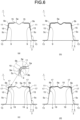
- the crashworthiness energy absorbing effect can be expected to be improved if a closed cross section space is formed between the closed cross section space forming wall member 9 and the inner surface of the corner portion 5b where cracking is particularly likely to occur at crash, and the resin 11 is provided in such a closed cross section space. Therefore, as illustrated in FIG. 6 , the resin 11 may be provided in the closed cross section space formed between the closed cross section space forming wall member 9 and the corner portion 5b.
- each closed cross section space forming wall member 9 may be disposed so as to straddle the respective corner portions 5b on both sides of the top portion 5a, and each closed cross section space forming wall member 9 may have one end side joined to the inner surface of the side wall portion 5c continuous from the corner portion 5b by the join portion 15 and the other end side joined to the inner surface of the top portion 5a continuous from the corner portion 5b by the join portion 15 ( FIG. 6(a) ).
- one closed cross section space forming wall member 9 may be disposed so as to straddle the top portion 5a and the two corner portions 5b, and have both end portions joined to the inner surfaces of the pair of side wall portions 5c by the join portions 15, and the central portion in contact with the inner surface of the top portion 5a ( FIG. 6(b) ).
- the central portion may be joined to the inner surface of the top portion 5a.
- the closed cross section space between the outer part 5 and the closed cross section space forming wall member 9 does not need to be filled with the resin 11, and as illustrated in FIGS. 6(c) and 6(d) , the resin 11 may be provided in at least a corner area 19 in the closed cross section space, and at least one area of areas on both sides of the resin 11 in the closed cross section space may be a cavity 17.
- the corner area 19 in the closed cross section space refers to an area partitioned by straight lines connecting boundaries 5e between the curve and the straight line of the outer part 5 and boundaries 9b between the curve and the straight line of the closed cross section space forming wall member 9 as illustrated in a partially enlarged view (a portion surrounded by a broken line circle) of FIG. 6(c) .
- the resin 11 When the resin 11 is provided in at least the corner area 19 in the closed cross section space area, the resin 11 may be provided in the corner area 19 as illustrated in FIGS. 6(c) and 6(d) , and the end portion of the resin 11 may extend to the top portion 5a side or the side wall portion 5c side in the closed cross section space.
- the cavity 17 refers to an area where the resin 11 is not provided between the outer part 5 and the closed cross section space forming wall member 9 in the closed cross section space, and where the resin 11 is not in contact with the outer part 5 or the closed cross section space forming wall member 9.
- the resin 11 may be provided in the closed cross section space formed between the closed cross section space forming wall member 9 and the inner surfaces of the corner portion 5b and the side wall portion 5c by the closed cross section space forming wall member 9.
- two closed cross section space forming wall members 9 may be used and the join portion 15 may be provided in each of the top portion 5a and the side wall portion 5c ( FIG.
- one closed cross section space forming wall member 9 may be used and the central portion of the closed cross section space forming wall member 9 may be in contact with or joined to the top portion 5a of the outer part 5, and the join portions 15 may be provided in the pair of side wall portions 5c so that a closed cross section space is formed between the closed cross section space forming wall member 9 and the respective corner portions 5b ( FIG. 7(b) ).
- both side ends of the closed cross section space forming wall member 9 with a hat-shaped cross section may be joined to the outer part 5 and the inner part 7 at the join portion 15.
- the closed cross section space formed between the closed cross section space forming wall member 9 and each of the outer part 5 and inner part 7 does not need to be filled with the resin 11.
- the resin 11 is placed in at least the corner area 19 in the closed cross section space, and any one of the areas on both sides of the resin 11 in the closed cross section space is used as the cavity 17, thereby also reducing the weight of the automotive body.
- the automotive crashworthiness energy absorptive part 1 includes the tubular member 3 including the outer part 5 with a hat-shaped cross section and the inner part 7 in a flat sheet shape, but the present invention is not limited thereto.
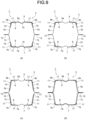
- one aspect may provide the tubular member 3 cylindrically formed by opposing the outer part 5 with a hat-shaped cross section and the inner part 7 with a hat-shaped cross section to each other, and joining the flange portions of the outer part 5 and the inner part 7 to each other.
- FIG. 9(a) illustrates an example in which the closed cross section space forming wall member 9 is disposed and the resin 11 is provided in the aspect illustrated in FIG. 6(d) .
- FIG. 9(b) illustrates an example in which the closed cross section space forming wall member 9 is disposed and the resin 11 is provided in the aspect illustrated in FIG. 6(c) .
- FIG. 9(c) illustrates an example in which the closed cross section space forming wall member 9 is disposed and the resin 11 is provided in the aspect illustrated in FIG. 7(a) .
- FIG. 9(d) illustrates an example in which the closed cross section space forming wall member 9 is disposed and the resin 11 is provided in the aspect illustrated in FIG. 8 .
- the outer part 5 is denoted by the same reference numerals as those in FIGS. 5 to 8
- the inner part 7 is denoted by reference numerals corresponding to those of the outer part 5.
- FIGS. 5 , 6(a), 6(b), and 6(d) and the aspect illustrated in FIG. 7(b) can also be applied to the tubular member formed by opposing the outer part with a hat-shaped cross section and the inner part with a hat-shaped cross section to each other and joining the flange portions to each other.
- FIG. 9 illustrates an example in which the outer part 5 and the inner part 7 have the same hat-shaped cross section, the outer part 5 and the inner part 7 may have different hat-shaped cross sections.
- a load-stroke curve indicating a relationship between the crashworthiness load and the axial crushing deformation amount (stroke) when the test body length (an axial length L 0 of a test body 31) was axially crushed and deformed by 80 mm from 200 mm to 120 mm was measured by inputting the crashworthiness load axially to the test body 31 at a test speed of 17.8 m/s, as illustrated in FIG. 3 , and the deformation state was photographed by a high speed camera. Further, absorbing energy at a stroke from 0 to 80 mm was determined from the measured load-stroke curve.
- FIG. 10 illustrates the structure and shape of the test body 31 used in invention examples.
- the axial crushing test was performed using the automotive crashworthiness energy absorptive part 1 ( FIGS. 1 and 2 ) according to the embodiment of the present invention described above as the test body 31.
- the test body 31 includes the tubular member 3 in which the outer part 5 and the inner part 7 are joined to each other by spot welding, the closed cross section space is formed between the outer part 5 and the closed cross section space forming wall member 9, and the resin 11 is provided in the respective corner areas on both sides of the top portion in the closed cross section space.
- the gap heights between the outer part 5 and the closed cross section space forming wall member 9 were set to 8 mm, 3 mm, and 1 mm ( FIGS. 10(a) to (c) ).
- Steel sheets with tensile strengths of 590 MPa class to 1180 MPa class and a thickness of 1.2 mm or 1.4 mm were used for the outer part 5, and steel sheets with a tensile strength of 590 MPa class and a thickness of 1.2 mm were used for the inner part 7.
- Steel sheets with a tensile strength of 270 MPa class and a thickness of 0.5 mm were used for the closed cross section space forming wall member 9.
- the resin 11 was obtained by heat-treating a rubber-modified epoxy resin and a hardener at a predetermined heating temperature and heating time, and the values of the tensile breaking elongation, adhesive strength, compressive nominal stress of the heat-treated resin 11 were set within the range of the present invention.
- the water resistance can be changed by sequentially adjusting monomer components constituting the resin 11, and the tensile breaking elongation and the compressive nominal stress are changed by changing the monomer components.
- the tensile breaking elongation, adhesive strength, and compressive nominal stress of the resin 11 were determined by separately implementing the following test methods.
- JIS No. 6 dumbbell JIS No. 6 dumbbell
- an adherend piece 23 and an adherend piece 25 were steel sheets (SPCC) with a width of 25 mm, a thickness of 1.6 mm, and a length of 100 mm, an uncured resin 27 was placed on the adhesion portion (width 25 mm and length 10 mm), and the steel sheets were thermally cured under the condition of retention at 180 °C for 20 minutes in a state in which the thickness was adjusted to 0.15 mm to prepare a test piece 21.
- a tensile test was performed on the test piece 21 at a tensile speed of 5 mm/minute until the adherend piece 23 or the adherend piece 25 fractured from the resin 27, and the load at fracture was measured. Then, a value obtained by dividing the load at fracture by the area of the adhesion portion (adhesion area: width 25 mm ⁇ length 10 mm) was defined as the adhesion shear strength.
- the gap between two steel sheets was adjusted to 3 mm, an uncured resin was placed between the steel sheets and thermally cured under the condition of 180 °C ⁇ 20 minutes retention, and then the steel sheets were peeled off to prepare a flat sheet-like resin with a thickness of 3 mm. Then, the flat sheet-like resin was cut into a cylindrical shape with a diameter of 20 mm to obtain a cylindrical resin. Then, using the circular surface of the cylindrical resin with a diameter of 20 mm as a compression surface, a value obtained by dividing a load when the test piece is compressed to a nominal strain of 10% at a test speed of 2 mm/min by the cross-sectional area of the initial cylindrical resin was defined as the compressive nominal stress.
- the test piece 21 illustrated in FIG. 11 was immersed in warm water at 70 °C for 72 hours, and then a tensile test was performed on the test piece 21 at a tensile speed of 5 mm/min until the adherend piece 23 or the adherend piece 25 fractured from the resin 27, and the peeling state of the adherend piece 23 or the adherend piece 25 and the resin 27 was observed.
- an axial crushing test was performed in the same manner as in the invention examples, by defining as comparative examples cases where a test body 33 ( FIG. 12 ) having the same shape as the tubular member 3 and the closed cross section space forming wall member 9 in the invention examples and not provided with the resin was used as a comparison target, and cases where the physical properties of the resin 11 fell outside the range of the present invention in the test body 31 having the same shape as that in the invention examples.
- Table 1 illustrates the conditions of the structure of the test body, type of resin, tensile breaking elongation, adhesive strength, and compressive nominal stress at a compressive nominal strain of 10%, which are used in the invention examples and the comparative examples.
- Comparative Examples 1 to 4 the test body 33 not provided with the resin was used.
- the test body 31 was used in which the type of the resin 11 was epoxy resin or urethane resin, and at least one of the tensile breaking elongation, adhesive strength, and compressive nominal stress fell outside the range of the present invention.
- Comparative Examples 8 to 14 the test body 31 having the tensile breaking elongation of the resin 11 of 80% or more was used.
- FIGS. 13 and 14 illustrate the measurement results of the load-stroke curve when the axial crushing test was performed using the test body 33 according to Comparative Example 1 and the test body 31 ( FIG. 10(a) ) according to Invention Example 1, respectively.
- FIGS. 13 and 14 are load-stroke curves having the stroke (mm) representing the deformation amount in the axial direction of the test body from the crash start on the horizontal axis, and the crashworthiness load (kN) input to the test body on the vertical axis.
- the absorbing energy illustrated in the graph is the amount of crashworthiness energy absorbed at strokes of 0 to 80 mm.
- Comparative Example 1 illustrated in FIG. 13 is a result of the test body 33 ( FIG. 12 ) not provided with the resin, and the crashworthiness load input to the test body 33 showed the maximum value (about 300 kN) immediately after the start of input, and thereafter, the value of the crashworthiness load fluctuated with the buckling of the tubular member 3.
- the absorbing energy at the end of the test when the stroke reached 80 mm was 6.5 kJ.
- the maximum value immediately after the start of input of the crashworthiness load was about 400 kN and was significantly improved as compared with Comparative Example 1 described above.
- the crashworthiness load after a stroke of 10 mm was higher than that in Comparative Example 1.
- the absorbing energy at strokes of 0 to 80 mm was also significantly improved to 13.8 kJ as compared with Comparative Example 1.
- the test body weight in Table 1 is the sum of the weights of the outer part 5, the inner part 7, the closed cross section space forming wall member 9, and the resin 11 in the test body 31 provided with the resin 11.
- the test body weight is the sum of the weights of the outer part 5, the inner part 7, and the closed cross section space forming wall member 9 in the test body 33 not provided with the resin.
- the test body 31 ( FIG. 10(c) ) was used in which the thickness of the resin 11 was 1 mm, which was smaller than that in Invention Example 1.
- the test body weight in Invention Example 2 was 1.11 kg, which was lighter than that in Invention Example 1.
- the test body 31 ( FIG. 10(c) ) was used in which the tensile strength of the steel sheet used for the outer part 5 was 1180 MPa class and the thickness of the resin 11 was 1 mm.
- the test body weight in Invention Example 3 was 1.12 kg, which was lighter than that in Invention Example 1.
- the test body 31 ( FIG. 10(b) ) was used in which the tensile strength of the steel sheet used for the outer part 5 was 590 MPa class and the thickness of the resin 11 was 3 mm.
- the test body weight in Invention Example 4 was 1.17 kg, which was lighter than that in Invention Example 1.
- the test body 31 ( FIG. 10(a) ) was used in which the tensile strength of the steel sheet used for the outer part 5 was 590 MPa class and the thickness of the resin 11 was 8 mm.
- the test body 31 ( FIG. 10(c) ) was used in which the tensile strength of the steel sheet used for the outer part 5 was 1180 MPa class and the thickness of the resin 11 was 1 mm.
- the test body weight in Invention Example 6 was 1.11 kg, which was lighter than that in Invention Example 1.
- the test body 31 ( FIG. 10(b) ) was used in which the tensile strength of the steel sheet used for the outer part 5 was 590 MPa class and the thickness of the resin 11 was 3 mm.
- the test body weight in Invention Example 7 was 1.17 kg, which was lighter than that in Invention Example 1.
- Comparative Example 1 the test body 33 ( FIG. 12 ) not provided with the resin was used, and the test body weight was 1.06 kg. As illustrated in FIG. 13 described above, the absorbing energy was 6.5 kJ, and the absorbing energy per unit weight was 6.1 kJ/kg.
- Comparative Example 2 the test body 33 having the same shape as that in Comparative Example 1 and using a steel sheet with a thickness of 1.4 mm for the outer part 5 was used, and the test body weight was 1.17 kg.
- the absorbing energy in Comparative Example 2 was 7.0 kJ and the absorbing energy per unit weight was 6.0 kJ/kg, and the absorbing energy was larger than that in Comparative Example 1 but fell short of the absorbing energy in Invention Examples 1 to 7.
- Comparative Example 3 the test body 33 having the same shape as that in Comparative Example 1 and using a steel sheet with a tensile thickness of 980 MPa for the outer part 5 was used, and the test body weight was 1.06 kg.
- the absorbing energy in Comparative Example 3 was 8.1 kJ and the absorbing energy per unit weight was 7.6 kJ/kg, and both the absorbing energy and the absorbing energy per unit weight were larger than those in Comparative Example 1 but fell short of those in Invention Examples 1 to 7.
- Comparative Example 4 the test body 33 having the same shape as that in Comparative Example 1 and using a steel sheet with a tensile thickness of 1180 MPa for the outer part 5 was used, and the test body weight was 1.07 kg.
- the absorbing energy in Comparative Example 4 was 8.5 kJ and the absorbing energy per unit weight was 7.9 kJ/kg, and both the absorbing energy and the absorbing energy per unit weight were larger than those in Comparative Example 1 but fell short of those in Invention Examples 1 to 7.
- Comparative Example 5 Comparative Example 6, and Comparative Example 7, the test bodies have the same shape as the test body 31 ( FIG. 10 ) according to Invention Example 2, but the type of the resin or at least one of the tensile breaking elongation, adhesive strength, and compressive nominal stress of the resin falls outside the range of the present invention.
- Comparative Example 8 is an example in which the test body has the same shape as the test body 31 according to Invention Example 1 but uses the resin with a tensile breaking elongation of 80%, which is inferior in water resistance evaluation.
- Comparative Example 9 is an example in which the test body has the same shape as the test body 31 according to Invention Example 2 but uses the resin with a tensile breaking elongation of 100%, which is inferior in water resistance evaluation.
- the test body weight was 1.11 kg, which was lighter than that in Invention Example 1.
- interfacial peeling occurred in the water resistance evaluation.
- Comparative Example 10 is an example in which the test body has the same shape as the test body 31 according to Invention Example 3 but uses the resin with a tensile breaking elongation of 100%, which is inferior in water resistance evaluation.
- the test weight was 1.12 kg, which was the same as that in Invention Example 3, but interfacial peeling occurred in the water resistance evaluation.
- Comparative Example 11 is an example in which the test body has the same shape as the test body 31 according to Invention Example 4 but uses the resin with a tensile breaking elongation of 90%, which is inferior in water resistance evaluation.
- the test weight was 1.17 kg, which was the same as that in Invention Example 4, but interfacial peeling occurred in the water resistance evaluation.
- Comparative Example 12 is an example in which the test body has the same shape as the test body 31 according to Invention Example 5 but uses the resin with a tensile breaking elongation of 85%, which is inferior in water resistance evaluation.
- the test weight was 1.24 kg, which was the same as that in Invention Example 5, but interfacial peeling occurred in the water resistance evaluation.
- Comparative Example 13 is an example in which the test body has the same shape as the test body 31 according to Invention Example 6 but uses the resin with a tensile breaking elongation of 110%, which is inferior in water resistance evaluation.
- the test weight was 1.11 kg, which was the same as that in Invention Example 6, but interfacial peeling occurred in the water resistance evaluation.
- Comparative Example 14 is an example in which the test body has the same shape as the test body 31 according to Invention Example 7 but uses the resin with a tensile breaking elongation of 100%, which is inferior in water resistance evaluation.
- the test weight was 1.17 kg, which was the same as that in Invention Example 7, but interfacial peeling occurred in the water resistance evaluation.
- the automotive crashworthiness energy absorptive part according to the present invention can improve the absorptive properties of crashworthiness energy during axial crush when a crashworthiness load is input in the axial direction, and has excellent water resistance.
- an automotive crashworthiness energy absorptive part capable of improving the crashworthiness energy absorbing effect while the automotive crashworthiness energy absorptive part axially crushes in a bellows-shaped manner when a crashworthiness load is input from the front or the rear of the automotive body such as the front side member or crash box, and capable of ensuring water resistance and thereby stably maintaining an excellent crashworthiness energy absorbing effect without change even when used for a long period of time in the use environment of an actual vehicle such as rainy weather or high humidity.
Landscapes
- Engineering & Computer Science (AREA)
- Mechanical Engineering (AREA)
- Chemical & Material Sciences (AREA)
- Combustion & Propulsion (AREA)
- Transportation (AREA)
- Architecture (AREA)
- Structural Engineering (AREA)
- General Engineering & Computer Science (AREA)
- Body Structure For Vehicles (AREA)
- Vibration Dampers (AREA)
- Laminated Bodies (AREA)
Abstract
Description
- The present invention relates to an automotive crashworthiness energy absorptive part, and more particularly to an automotive crashworthiness energy absorptive part that absorbs crashworthiness energy by crushing axially in a longitudinal direction when a crashworthiness load is input from the front or the rear of an automotive body.
- As a technique for improving crashworthiness energy absorptive properties of an automobile, there are many techniques such as optimization of a shape, a structure, a material, and the like of automotive parts. Furthermore, in recent years, many techniques have been proposed in which an automotive part having a closed cross section shape is filled with a resin (for example, a foamed resin) to achieve both improvement in crashworthiness energy absorptive properties of the automotive part and weight reduction of the automotive body.
- For example,
Patent Literature 1 discloses a technique in which a structural part configured to form a closed space inside by aligning the directions of the top portions and overlapping the flanges of hat-shaped cross section parts such as a side sill, a floor member, and a pillar with each other is filled with a foaming filler to improve the bending strength and torsional stiffness of the structural part with a minimum weight increase, and thereby to improve the rigidity and collision safety of the automotive body. - In addition,
Patent Literature 2 discloses a technique in which, when an internal space of a structure with a closed cross section such as a pillar formed by opposing hat-shaped cross section parts to each other and joining the flange portions is filled with a foamed body with high rigidity, the foamed body is fixed by action of the compressive counterforce due to filling and foaming of the foamed body with high rigidity to improve the vibration damping performance for suppressing the transmission of vibration sound while improving the strength, rigidity, and impact energy absorptive properties. -
- Patent Literature 1:
JP 2006-240134 A - Patent Literature 2:
JP 2000-318075 A - According to the techniques disclosed in
Patent Literature 1 andPatent Literature 2, by filling the automotive part with the foaming filler or the foamed body, it is possible to improve strength against bending deformation of the automotive part, impact energy absorptive properties against bending deformation due to crash, and furthermore, rigidity against torsional deformation, and thus to suppress the deformation of the automotive part. However, there is a problem that it is difficult to improve the crashworthiness energy absorptive properties by applying the technique in which the automotive part is filled with the foaming filler or the foamed body, in the case of automotive parts that absorb crashworthiness energy by generating buckling deformation in a bellows-shaped manner during axial (longitudinal) crush when a crashworthiness load is input from the front or the rear of the automobile, such as a front side member and a crash box covered by the present invention. - Further, since the conventional automotive parts as described above have low water resistance, there is a problem that the crashworthiness energy absorptive properties are reduced depending on the use environment such as rainy weather or high humidity if they are used for a long period of time.
- The present invention has been made in view of the above problems, and an object of the present invention is to provide an automotive crashworthiness energy absorptive part capable of improving the crashworthiness energy absorbing effect while the automotive crashworthiness energy absorptive part axially crushes in a bellows-shaped manner when a crashworthiness load is input from the front or the rear of the automotive body such as the front side member or crash box, and capable of ensuring water resistance and thereby stably maintaining an excellent crashworthiness energy absorbing effect without change even when used for a long period of time in the use environment of an actual vehicle such as rainy weather or high humidity.
- An automotive crashworthiness energy absorptive part according to a first aspect of the present invention absorbs crashworthiness energy by crushing axially when a crashworthiness load is input from a front side or a rear side of an automotive body, and includes: a tubular member formed of a steel sheet with a tensile strength of 590 MPa to 1180 MPa, the tubular member including a top portion and a pair of side wall portions continuous from both ends of the top portion via corner portions; a closed cross section space forming wall member formed of a steel sheet with a tensile strength lower than that of the tubular member, the closed cross section space forming wall member being disposed on an inner surface side of the tubular member and forming a closed cross section space between the closed cross section space forming wall member and at least the corner portion; and a resin provided in the closed cross section space, wherein the resin contains a rubber-modified epoxy resin and a hardener, and has a tensile breaking elongation of 2% or more and less than 80%, an adhesive strength with the tubular member and the closed cross section space forming wall member of 12 MPa or more, and a compressive nominal stress of 6 MPa or more at a compressive nominal strain of 10%.
- An automotive crashworthiness energy absorptive part according to a second aspect of the present invention absorbs crashworthiness energy by crushing axially when a crashworthiness load is input from a front side or a rear side of an automotive body, the automotive crashworthiness energy absorptive part comprising: a tubular member formed of a steel sheet with a tensile strength of 590 MPa to 1180 MPa, the tubular member including a top portion and a pair of side wall portions continuous from both ends of the top portion via corner portions; a closed cross section space forming wall member formed of a steel sheet with a tensile strength lower than that of the tubular member, the closed cross section space forming wall member being disposed on an inner surface side of the tubular member and forming a closed cross section space between the closed cross section space forming wall member and at least the corner portion; and a resin provided in the closed cross section space, wherein the resin contains a rubber-modified epoxy resin, and has a tensile breaking elongation of 2% or more and less than 80%, an adhesive strength with the tubular member and the closed cross section space forming wall member of 12 MPa or more, and a compressive nominal stress of 6 MPa or more at a compressive nominal strain of 10%.
- The closed cross section space forming wall member may be disposed so as to straddle the top portion and the corner portion, and may have both end portions joined to inner surfaces of the pair of side wall portions and a central portion in contact with the inner surface of the top portion.
- The central portion of the closed cross section space forming wall member may be joined to the inner surface of the top portion.
- The closed cross section space forming wall member may be disposed so as to straddle the corner portion, and may have one end portion joined to the inner surface of the side wall portion continuous from the corner portion and the other end joined to the inner surface of the top portion continuous from the corner portion.
- The resin may be provided in at least a corner area in the closed cross section space, and at least one of areas on both sides of the resin in the closed cross section space is a cavity.
- According to the present invention, it is possible to, in a process of compressive deformation of a tubular member that absorbs crashworthiness energy by crushing axially when a crashworthiness load is input from the front or the rear of the automotive body, repeatedly generate buckling deformation in a bellows-shaped manner without reducing the deformation resistance of the tubular member to significantly improve a crashworthiness energy absorbing effect, and to ensure water resistance and thereby to stably maintain an excellent crashworthiness energy absorbing effect without change even when used for a long period of time in the use environment of an actual vehicle such as rainy weather or high humidity.
-
-
FIG. 1 is an explanatory view for explaining a configuration of an automotive crashworthiness energy absorptive part according to an embodiment of the present invention. -
FIG. 2 is a cross-sectional view of the automotive crashworthiness energy absorptive part according to the present embodiment. -
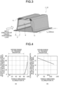
FIG. 3 is a view for explaining a crashworthiness load input to the automotive crashworthiness energy absorptive part in the present embodiment and examples. -
FIG. 4 is a diagram illustrating characteristics related to water resistance of a resin used in the automotive crashworthiness energy absorptive part according to the present embodiment ((a) interfacial peeling and (b) cohesive fracture strength). -
FIG. 5 is a cross-sectional view illustrating a specific example of a closed cross section space forming wall member used in the automotive crashworthiness energy absorptive part according to the present embodiment (part 1) . -
FIG. 6 is a cross-sectional view illustrating a specific example of the closed cross section space forming wall member used in the automotive crashworthiness energy absorptive part according to the present embodiment (part 2) . -
FIG. 7 is a cross-sectional view illustrating a specific example of the closed cross section space forming wall member used in the automotive crashworthiness energy absorptive part according to the present embodiment (part 3) . -
FIG. 8 is a cross-sectional view illustrating a specific example of the closed cross section space forming wall member used in the automotive crashworthiness energy absorptive part according to the present embodiment (part 4) . -
FIG. 9 is a cross-sectional view illustrating a specific embodiment of the automotive crashworthiness energy absorptive part according to the present invention. -
FIG. 10 is a cross-sectional view illustrating a structure of a test body used as an invention example in an axial crushing test in Examples. -
FIG. 11 is a view illustrating a test piece and a test method used for measurement of adhesive strength of a resin and a water resistance evaluation test in Examples. -
FIG. 12 is a view illustrating a structure of a test body used as a comparison target in the axial crushing test in Examples. -
FIG. 13 is a diagram illustrating measurement results of a crashworthiness load and the amount of axial crushing deformation (stroke) when the axial crushing test is performed using the automotive crashworthiness energy absorptive part according to a comparative example as the test body in Examples. -
FIG. 14 is a diagram illustrating measurement results of the crashworthiness load and the amount of axial crushing deformation (stroke) when the axial crushing test is performed using the automotive crashworthiness energy absorptive part according to an invention example as the test body in Examples. - An automotive crashworthiness energy absorptive part according to an embodiment of the present invention will be described below with reference to
FIGS. 1 to 8 . Note that, in the description and the drawings, elements having substantially the same function and configuration are denoted by the same reference numerals to omit redundant description. - An automotive crashworthiness energy
absorptive part 1 according to the present embodiment absorbs crashworthiness energy by crushing axially when a crashworthiness load is input from the front or the rear of an automotive body, and includes atubular member 3, a closed cross section space formingwall member 9, and aresin 11, as illustrated inFIGS. 1 to 3 . - The
tubular member 3 is tubularly formed by joining aflange portion 5d of anouter part 5 with a hat-shaped cross section having atop portion 5a, a pair ofside wall portions 5c continuous from both ends of thetop portion 5a via acorner portion 5b, and theflange portion 5d continuous from theside wall portion 5c, and both ends of a flat sheet-shapedinner part 7 at ajoin portion 13. Here, thecorner portion 5b is a bent portion connecting thetop portion 5a and theside wall portion 5c, and is a portion between aboundary 5e between a curve and a straight line on thetop portion 5a side and aboundary 5e between a curve and a straight line on theside wall portion 5c side (seeFIG. 2 ). The same applies to the following description. - The
outer part 5 and theinner part 7 constituting thetubular member 3 are both formed of a steel sheet with a tensile strength of 590 MPa to 1180 MPa. Here, examples of the type of the steel sheet include a cold rolled steel sheet, a hot rolled steel sheet, a zincbased coating steel sheet, a zinc alloy coating steel sheet, and an aluminum alloy coating steel sheet. - The
tubular member 3 is used for automotive parts having a closed cross-sectional structure, such as a front side member extending in the front-rear direction of the automotive body at left and right positions of the front portion of the automotive body and constituting a part of an automotive body frame, and a crash box provided at the front end or rear end of the automotive body frame. Such automotive parts are disposed on the automotive body such that the axial direction (longitudinal direction) of thetubular member 3 coincides with the front-rear direction of the automotive body. With this configuration, thetubular member 3 absorbs crashworthiness energy by crushing axially when a crashworthiness load is input from the front or the rear of the automotive body. - The closed cross section space forming
wall member 9 is formed of a steel sheet with a lower tensile strength than the tubular member 3 (for example, 270 MPa class, 440 MPa class, etc.). As illustrated inFIG. 2 , the closed cross section space formingwall member 9 is disposed on the inner surface side of thetubular member 3, and forms a closed cross section space between the closed cross section space formingwall member 9 and at least thecorner portion 5b, including a case where the closed cross section space formingwall member 9 is joined to, brought into contact with, or divided at the vicinity of the center of thetop portion 5a. - In the automotive crashworthiness energy
absorptive part 1, as illustrated inFIG. 2 , the closed cross section space formingwall member 9 is a member having a substantially U-shaped cross section disposed so as to include thecorner portion 5b and straddle thecorner portion 5b between theouter part 5 and theinner part 7. Both end portions of the closed cross section space formingwall member 9 are joined to the pair ofside wall portions 5c of theouter part 5, and a closed cross section space is formed between the closed cross section space formingwall member 9 and the inner surfaces of thetop portion 5a, thecorner portion 5b, and a part of theside wall portion 5c of theouter part 5 of thetubular member 3. - The closed cross section space formed between the closed cross section space forming
wall member 9 and theouter part 5 refers to a space in which a cross-sectional shape in a direction intersecting the axial direction of thetubular member 3 illustrated inFIG. 1 is a closed cross section, and the closed cross section is continuously formed along the axial direction of thetubular member 3. Both end portions of the closed cross section space formingwall member 9 and the inner surface of theside wall portion 5c or the inner surface of thetop portion 5a are joined by spot welding or the like, for example. - The
resin 11 is provided over the entire length of the closed cross section space in the axial direction formed between the closed cross section space formingwall member 9 and theouter part 5. Theresin 11 may be provided in a part of the closed cross section space in the axial direction, for example, in a part of the side to which a crashworthiness load is input. - The
resin 11 contains a rubber-modified epoxy resin and a hardener, and undergoes a heat treatment at a predetermined temperature and for a predetermined time so that the resin can be adhered to theouter part 5 and the closed cross section space formingwall member 9 due to the adhesive capacity of theresin 11 itself. Further, theresin 11 has the following physical properties: the tensile breaking elongation is 2% or more and less than 80%, the adhesive strength with thetubular member 3 and the closed cross section space formingwall member 9 is 12 MPa or more, and the compressive nominal stress at a compressive nominal strain of 10% is 6 MPa or more. Each of these physical properties is a value of a heat-treatedresin 11. - The reason why the
resin 11 contains the rubber-modified epoxy resin and the hardener is that, when thetubular member 3 crushes and deforms axially in a bellows-shaped manner when a crashworthiness load is input to thetubular member 3, theresin 11 can deform so as to follow the deformation of thetubular member 3 by being adhered to thetubular member 3 and the closed cross section space formingwall member 9 with an adhesive strength of 12 MPa or more after theresin 11 is thermally cured by the heat treatment. - Further, the method for determining the physical properties of the resin 11 (tensile breaking elongation, adhesive strength, and compressive nominal stress) and the reason why each physical property is defined as described above are as follows:
- An uncured resin is placed between two steel sheets adjusted to have a predetermined gap, and thermally cured under predetermined conditions, the steel sheets are peeled off to prepare a flat sheet-like resin, and the flat sheet-like resin is processed into a predetermined shape to prepare a test piece. Next, a tensile test is performed at a predetermined tensile speed until the resin fractures to measure the inter-marker elongation at resin fracture. Then, a value obtained by dividing the measured inter-marker elongation at resin fracture by the initial inter-marker distance and expressing the result as a percentage is defined as the tensile breaking elongation.
- Since the automotive body is usually exposed to rain, splashing rain water, and a high-humidity environment, a resin constituting a part of the automotive body is also required to have water resistance. For this reason, it is necessary to maintain water resistance that can ensure adhesive properties (adhesive strength) for preventing interfacial peeling of the resin of the automotive crashworthiness energy absorptive
part 1 for a long period of time. Therefore, in the automotive crashworthiness energy absorptivepart 1, since the tensile breaking elongation is 2% or more and less than 80%, the adhesion between theresin 11 and thetubular member 3 or the closed cross section space formingwall member 9 is not reduced even in the use environment such as rainy weather or high humidity, making it possible to ensure water resistance capable of maintaining the crashworthiness energy absorbing effect. - If the tensile breaking elongation is less than 2%, the
resin 11 is likely to be cracked or fractured in the process of the axial crush of thetubular member 3 and peeled off from thetubular member 3 or the closed cross section space formingwall member 9, and as a result, the buckling strength and the deformation resistance are likely to be reduced. - On the other hand, if the tensile breaking elongation exceeds 80%, the water resistance of the
resin 11 cannot be maintained, causing theresin 11 to be peeled off from thetubular member 3 or the closed cross section space formingwall member 9 in the process of the axial crush of thetubular member 3, and as a result, the buckling resistance and the crash worthiness are likely to be reduced. - The index representing the water resistance of the resin includes a characteristic that the resin is unlikely to be peeled off from a steel surface (steel interface) even in the use environment such as rainy weather or high humidity, and a characteristic that the resin is unlikely to swell and fracture. These characteristics of the resin can be obtained, for example, by performing a water resistance evaluation test in which a test piece obtained by overlapping and adhering two steel sheets is immersed in warm water at a predetermined temperature for a predetermined time, then a tensile load is applied until the adhesive surface of the test piece fractures, and the state of the resin on the fractured adhesive surface is obtained.
-
FIG. 4 illustrates an example of the characteristics of the resin obtained from the above-described water resistance evaluation test.FIG. 4(a) is a graph illustrating the relationship between the resin interfacial peeling area ratio (= (the area of the adhesive surface from which the resin was peeled off at fracture)/(the area of the adhesive surface of the test piece) × 100), which is the ratio of the area of the resin peeled off from the adhesive surface, and the tensile breaking elongation in the water resistance evaluation test. On the other hand,FIG. 4(b) is a graph illustrating the relationship between the cohesive fracture strength when the resin fractures from inside (cohesive fracture) and the tensile breaking elongation of the resin in the above-described water resistance evaluation test. - In the present invention, since the crash worthiness is reduced when the
resin 11 is peeled off from thetubular member 3 or the closed cross section space formingwall member 9 made of a steel sheet, a characteristic that the resin is unlikely to be peeled off from the steel surface (steel interface) is important as water resistance. As illustrated inFIG. 4(a) , interfacial peeling of the resin correlates with the tensile breaking elongation, and the interfacial peeling of the resin occurred and the water resistance was reduced when the tensile breaking elongation was 80% or more. Therefore, adhesion between theresin 11 and thetubular member 3 or the closed cross section space formingwall member 9 is reduced in the use environment such as rainy weather or high humidity, and theresin 11 is peeled off in the process of the axial crushing deformation of thetubular member 3 and as a result, the buckling resistance and the deformation resistance are likely to be reduced. - In addition, regarding the characteristic that the resin is less likely to swell and is less likely to fracture as well, as illustrated in
FIG. 4(b) , it is indicated that the interfacial peeling of the resin does not occur (resin interfacial peeling area ratio: 0%) even in the use environment such as rainy weather or high humidity, and the cohesive fracture strength can also be maintained at a sufficiently high value (12 MPa or more) if the tensile breaking elongation of the resin is less than 80%. - An uncured resin is placed between two steel sheets adjusted to have a predetermined gap, and thermally cured under predetermined conditions to prepare a test piece. Next, a tensile test is performed on the test piece at a predetermined tensile speed, and the load when the steel sheet and the resin fracture is measured. Then, a value obtained by dividing the measured load at fracture by the adhesive area between the steel sheet and the resin (= adhesion shear strength) is defined as the adhesive strength.
- When the obtained adhesive strength is 12 MPa or more, it is possible to prevent the
resin 11 from being peeled off from thetubular member 3 or the closed cross section space formingwall member 9 in the process of the axial crush of thetubular member 3, and thus to prevent the buckling resistance and the deformation resistance from being reduced. - An uncured resin is placed between two steel sheets adjusted to have a predetermined gap, and thermally cured under predetermined conditions, and then the steel sheets are peeled off to prepare a flat sheet-like resin. Next, the flat sheet-like resin is cut into a cylindrical shape to prepare a test piece. Then, using the circular surface of the test piece as a compression surface, a value obtained by dividing a load when the test piece is compressed to a nominal strain of 10% at a predetermined test speed by the cross-sectional area of the initial test piece is defined as the compressive nominal stress.
- When the compressive nominal stress at the compression nominal strain of 10% obtained as described above is 6 MPa or more, it is possible to have sufficient buckling strength such that the
resin 11 itself is not crushed and destroyed even if thetubular member 3 is deformed in a bellows-shaped manner in the axial crush process. - The types and compositions of the rubber-modified epoxy resin and the hardener, and the temperature and time for the heat treatment may be appropriately adjusted so that the tensile breaking elongation, adhesive strength, and compressive nominal stress of the
resin 11 fall within the above ranges. - In addition, the hardener may be optimally selected depending on the use environment, reaction temperature, and the like, from among a polyamine (aliphatic polyamine, aromatic amine, aromatic polyamine, and polyamidoamine), an anhydride, a phenolic, a thiol, a dicyandiamide serving as a thermal latent hardener, imidazole compounds, a ketimine, an organic acid hydrazide, and the like.
- As described above, in the automotive crashworthiness energy absorptive
part 1 according to the present embodiment, in the process of axial crush when a crashworthiness load is input to thetubular member 3, theresin 11 improves the buckling strength without being peeled off from thetubular member 3 or the closed cross section space formingwall member 9, and allows thetubular member 3 to repeatedly generate buckling in a bellows-shaped manner without reducing the deformation resistance of thetubular member 3, thus making it possible to improve the absorbability of the crashworthiness energy. Furthermore, the automotive crashworthiness energy absorptivepart 1 can maintain water resistance that does not reduce the adhesion of theresin 11 even in the use environment such as rainy weather or high humidity, and that can ensure an excellent crashworthiness energy absorption effect for a long period of time. - In the above description, the
resin 11 contains the rubber-modified epoxy resin and the hardener after the heat treatment. However, the hardener may not remain or not be detected in theresin 11 that has been heat-treated at a predetermined temperature for a predetermined time, depending on the amount of the hardener. - Therefore, as another aspect of the automotive crashworthiness energy absorptive
part 1 according to the embodiment of the present invention, the hardener may not be contained or not be detected in the heat-treatedresin 11, and theresin 11 may be adhered to theouter part 5 and the closed cross section space formingwall member 9 due to the adhesive capacity of theresin 11 itself when theresin 11 is heat-treated at a predetermined temperature and for a predetermined time. - Even when the hardener is not contained or not detected in the heat-treated
resin 11, theresin 11 has, as its physical properties, a tensile breaking elongation of 2% or more and less than 80%, an adhesive strength with thetubular member 3 and the closed cross section space formingwall member 9 of 12 MPa or more, and a compressive nominal stress at a compressive nominal strain of 10% of 6 MPa or more. The types and compositions of the rubber-modified epoxy resin and the hardener that are provided in the closed cross section space before the heat treatment, and the temperature and time for the heat treatment may be appropriately adjusted so that the tensile breaking elongation, adhesive strength, and compressive nominal stress of theresin 11 fall within the above ranges. - When the
resin 11 that contains the rubber-modified epoxy resin and in which the hardener is not contained or not detected has the physical properties that fall within the above ranges, it is possible to maintain water resistance that can ensure the adhesion of theresin 11, without reducing it, for a long period of time even in the use environment such as rainy weather or high humidity. In the process of the axial crush of thetubular member 3, theresin 11 improves the buckling strength without being peeled off from thetubular member 3 or the closed cross section space formingwall member 9, and allows thetubular member 3 to repeatedly generate buckling in a bellows-shaped manner without reducing the deformation resistance of thetubular member 3, thus making it possible to improve the absorbability of the crashworthiness energy. - In addition, in the automotive crashworthiness energy absorptive
part 1 according to the present embodiment, an example has been described in which the closed cross section space formingwall member 9 and theside wall portion 5c of theouter part 5 are joined by ajoin portion 15, and theresin 11 is provided between the closed cross section space formingwall member 9 and thetop portion 5a, thecorner portion 5b, or a part of theside wall portion 5c, as illustrated in the cross section inFIG. 2 , but the present invention is not limited thereto. - For example, as illustrated in
FIG. 5 , theside wall portion 9a of the closed cross section space formingwall member 9 may be merely 1/2 or less of the side wall height, and theresin 11 may be provided in the closed cross section space formed between the closed cross section space formingwall member 9 and the inner surface mainly of thetop portion 5a and thecorner portion 5b of theouter part 5. - Further, the crashworthiness energy absorbing effect can be expected to be improved if a closed cross section space is formed between the closed cross section space forming
wall member 9 and the inner surface of thecorner portion 5b where cracking is particularly likely to occur at crash, and theresin 11 is provided in such a closed cross section space. Therefore, as illustrated inFIG. 6 , theresin 11 may be provided in the closed cross section space formed between the closed cross section space formingwall member 9 and thecorner portion 5b. - In this case, two closed cross section space forming
wall members 9 may be disposed so as to straddle therespective corner portions 5b on both sides of thetop portion 5a, and each closed cross section space formingwall member 9 may have one end side joined to the inner surface of theside wall portion 5c continuous from thecorner portion 5b by thejoin portion 15 and the other end side joined to the inner surface of thetop portion 5a continuous from thecorner portion 5b by the join portion 15 (FIG. 6(a) ). Alternatively, one closed cross section space formingwall member 9 may be disposed so as to straddle thetop portion 5a and the twocorner portions 5b, and have both end portions joined to the inner surfaces of the pair ofside wall portions 5c by thejoin portions 15, and the central portion in contact with the inner surface of thetop portion 5a (FIG. 6(b) ). The central portion may be joined to the inner surface of thetop portion 5a. With these configurations, the closed cross section space formingwall member 9 forming the closed cross section space between the closed cross section space formingwall member 9 and thetop portion 5a can be small, and thus the weight of the automotive body can also be reduced. - The closed cross section space between the
outer part 5 and the closed cross section space formingwall member 9 does not need to be filled with theresin 11, and as illustrated inFIGS. 6(c) and 6(d) , theresin 11 may be provided in at least acorner area 19 in the closed cross section space, and at least one area of areas on both sides of theresin 11 in the closed cross section space may be acavity 17. - Here, in the closed cross section space formed between the
outer part 5 with a hat-shaped cross section and the closed cross section space formingwall member 9 with a hat-shaped cross section, for example, as illustrated inFIGS. 6(c) and 6(d) , thecorner area 19 in the closed cross section space refers to an area partitioned by straightlines connecting boundaries 5e between the curve and the straight line of theouter part 5 andboundaries 9b between the curve and the straight line of the closed cross section space formingwall member 9 as illustrated in a partially enlarged view (a portion surrounded by a broken line circle) ofFIG. 6(c) . - When the
resin 11 is provided in at least thecorner area 19 in the closed cross section space area, theresin 11 may be provided in thecorner area 19 as illustrated inFIGS. 6(c) and 6(d) , and the end portion of theresin 11 may extend to thetop portion 5a side or theside wall portion 5c side in the closed cross section space. For example, there may be thecavity 17 between theresins 11 placed in the left andright corner areas 19, and the left andright resins 11 may be separated by thecavity 17. - Further, the
cavity 17 refers to an area where theresin 11 is not provided between theouter part 5 and the closed cross section space formingwall member 9 in the closed cross section space, and where theresin 11 is not in contact with theouter part 5 or the closed cross section space formingwall member 9. - As described above, in the automotive crashworthiness energy absorptive
part 1 illustrated inFIGS. 6(a) to 6(d) , it is possible to significantly improve the crash worthiness while reducing the weight of the automotive crashworthiness energy absorptivepart 1 by limiting the closed cross section space formingwall member 9 and theresin 11 to the minimum size and amount. - In addition, as illustrated in
FIG. 7 , theresin 11 may be provided in the closed cross section space formed between the closed cross section space formingwall member 9 and the inner surfaces of thecorner portion 5b and theside wall portion 5c by the closed cross section space formingwall member 9. In this case, as inFIG. 6 , two closed cross section space formingwall members 9 may be used and thejoin portion 15 may be provided in each of thetop portion 5a and theside wall portion 5c (FIG. 7(a) ), or one closed cross section space formingwall member 9 may be used and the central portion of the closed cross section space formingwall member 9 may be in contact with or joined to thetop portion 5a of theouter part 5, and thejoin portions 15 may be provided in the pair ofside wall portions 5c so that a closed cross section space is formed between the closed cross section space formingwall member 9 and therespective corner portions 5b (FIG. 7(b) ). - Further, as illustrated in
FIG. 8 , both side ends of the closed cross section space formingwall member 9 with a hat-shaped cross section may be joined to theouter part 5 and theinner part 7 at thejoin portion 15. Also in this case, the closed cross section space formed between the closed cross section space formingwall member 9 and each of theouter part 5 andinner part 7 does not need to be filled with theresin 11. For example, as illustrated inFIG. 8 , theresin 11 is placed in at least thecorner area 19 in the closed cross section space, and any one of the areas on both sides of theresin 11 in the closed cross section space is used as thecavity 17, thereby also reducing the weight of the automotive body. - An example has been described in which the automotive crashworthiness energy absorptive
part 1 according to the present embodiment includes thetubular member 3 including theouter part 5 with a hat-shaped cross section and theinner part 7 in a flat sheet shape, but the present invention is not limited thereto. As illustrated inFIG. 9 , one aspect may provide thetubular member 3 cylindrically formed by opposing theouter part 5 with a hat-shaped cross section and theinner part 7 with a hat-shaped cross section to each other, and joining the flange portions of theouter part 5 and theinner part 7 to each other. -
FIG. 9(a) illustrates an example in which the closed cross section space formingwall member 9 is disposed and theresin 11 is provided in the aspect illustrated inFIG. 6(d) .FIG. 9(b) illustrates an example in which the closed cross section space formingwall member 9 is disposed and theresin 11 is provided in the aspect illustrated inFIG. 6(c) .FIG. 9(c) illustrates an example in which the closed cross section space formingwall member 9 is disposed and theresin 11 is provided in the aspect illustrated inFIG. 7(a) .FIG. 9(d) illustrates an example in which the closed cross section space formingwall member 9 is disposed and theresin 11 is provided in the aspect illustrated inFIG. 8 . InFIG. 9 , theouter part 5 is denoted by the same reference numerals as those inFIGS. 5 to 8 , and theinner part 7 is denoted by reference numerals corresponding to those of theouter part 5. - Similarly, the aspects illustrated in
FIGS. 5 ,6(a), 6(b), and 6(d) and the aspect illustrated inFIG. 7(b) can also be applied to the tubular member formed by opposing the outer part with a hat-shaped cross section and the inner part with a hat-shaped cross section to each other and joining the flange portions to each other. - Although
FIG. 9 illustrates an example in which theouter part 5 and theinner part 7 have the same hat-shaped cross section, theouter part 5 and theinner part 7 may have different hat-shaped cross sections. - An experiment for confirming the effect of the automotive crashworthiness energy absorptive part according to the present invention has been conducted, and the results thereof will be described below.
- In the experiment, an axial crushing test was performed on a test body imitating the automotive crashworthiness energy absorptive part according to the present invention. In the axial crushing test, a load-stroke curve indicating a relationship between the crashworthiness load and the axial crushing deformation amount (stroke) when the test body length (an axial length L0 of a test body 31) was axially crushed and deformed by 80 mm from 200 mm to 120 mm was measured by inputting the crashworthiness load axially to the
test body 31 at a test speed of 17.8 m/s, as illustrated inFIG. 3 , and the deformation state was photographed by a high speed camera. Further, absorbing energy at a stroke from 0 to 80 mm was determined from the measured load-stroke curve. -
FIG. 10 illustrates the structure and shape of thetest body 31 used in invention examples. In the invention examples, the axial crushing test was performed using the automotive crashworthiness energy absorptive part 1 (FIGS. 1 and 2 ) according to the embodiment of the present invention described above as thetest body 31. - The
test body 31 includes thetubular member 3 in which theouter part 5 and theinner part 7 are joined to each other by spot welding, the closed cross section space is formed between theouter part 5 and the closed cross section space formingwall member 9, and theresin 11 is provided in the respective corner areas on both sides of the top portion in the closed cross section space. The gap heights between theouter part 5 and the closed cross section space formingwall member 9 were set to 8 mm, 3 mm, and 1 mm (FIGS. 10(a) to (c) ). - Steel sheets with tensile strengths of 590 MPa class to 1180 MPa class and a thickness of 1.2 mm or 1.4 mm were used for the
outer part 5, and steel sheets with a tensile strength of 590 MPa class and a thickness of 1.2 mm were used for theinner part 7. Steel sheets with a tensile strength of 270 MPa class and a thickness of 0.5 mm were used for the closed cross section space formingwall member 9. - The
resin 11 was obtained by heat-treating a rubber-modified epoxy resin and a hardener at a predetermined heating temperature and heating time, and the values of the tensile breaking elongation, adhesive strength, compressive nominal stress of the heat-treatedresin 11 were set within the range of the present invention. - The water resistance can be changed by sequentially adjusting monomer components constituting the
resin 11, and the tensile breaking elongation and the compressive nominal stress are changed by changing the monomer components. The tensile breaking elongation, adhesive strength, and compressive nominal stress of theresin 11 were determined by separately implementing the following test methods. - The gap between two steel sheets was adjusted to 2 mm, an uncured resin was placed between the steel sheets and thermally cured under the condition of 180 °C × 20 minutes retention, and then the steel sheets were peeled off to prepare a flat sheet-like resin with a thickness of 2 mm. Subsequently, the flat sheet-like resin was processed into a dumbbell shape (JIS No. 6 dumbbell) to prepare a test piece, a tensile test was performed at a tensile speed of 2 mm/min until the resin fractures, and the inter-marker elongation at resin fracture was measured. Then, a value obtained by dividing the measured inter-marker elongation at resin fracture by the initial inter-marker distance (= 20 mm) was expressed as a percentage, and the result was defined as the tensile breaking elongation.
- As illustrated in
FIG. 11 , anadherend piece 23 and anadherend piece 25 were steel sheets (SPCC) with a width of 25 mm, a thickness of 1.6 mm, and a length of 100 mm, anuncured resin 27 was placed on the adhesion portion (width 25 mm andlength 10 mm), and the steel sheets were thermally cured under the condition of retention at 180 °C for 20 minutes in a state in which the thickness was adjusted to 0.15 mm to prepare atest piece 21. Next, a tensile test was performed on thetest piece 21 at a tensile speed of 5 mm/minute until theadherend piece 23 or theadherend piece 25 fractured from theresin 27, and the load at fracture was measured. Then, a value obtained by dividing the load at fracture by the area of the adhesion portion (adhesion area:width 25 mm ×length 10 mm) was defined as the adhesion shear strength. - The gap between two steel sheets was adjusted to 3 mm, an uncured resin was placed between the steel sheets and thermally cured under the condition of 180 °C × 20 minutes retention, and then the steel sheets were peeled off to prepare a flat sheet-like resin with a thickness of 3 mm. Then, the flat sheet-like resin was cut into a cylindrical shape with a diameter of 20 mm to obtain a cylindrical resin. Then, using the circular surface of the cylindrical resin with a diameter of 20 mm as a compression surface, a value obtained by dividing a load when the test piece is compressed to a nominal strain of 10% at a test speed of 2 mm/min by the cross-sectional area of the initial cylindrical resin was defined as the compressive nominal stress.
- The
test piece 21 illustrated inFIG. 11 was immersed in warm water at 70 °C for 72 hours, and then a tensile test was performed on thetest piece 21 at a tensile speed of 5 mm/min until theadherend piece 23 or theadherend piece 25 fractured from theresin 27, and the peeling state of theadherend piece 23 or theadherend piece 25 and theresin 27 was observed. The case where the cohesive fracture (where the area ratio of the resin remained on the resin adhesive surfaces of theadherend piece 23 and theadherend piece 25 when fracture occurred was 100%) occurred from inside of theresin 27 was evaluated as no interfacial peeling (o), and the case where interfacial peeling (where the surface of the adherend piece appeared when fracture occurred and the ratio of the resin remaining on the adhesive surfaces of theadherend piece 23 and theadherend piece 25 was less than 100%) occurred between theadherend piece 23 or theadherend piece 25 and theresin 27 was evaluated as ×. - In the present examples, an axial crushing test was performed in the same manner as in the invention examples, by defining as comparative examples cases where a test body 33 (
FIG. 12 ) having the same shape as thetubular member 3 and the closed cross section space formingwall member 9 in the invention examples and not provided with the resin was used as a comparison target, and cases where the physical properties of theresin 11 fell outside the range of the present invention in thetest body 31 having the same shape as that in the invention examples. Table 1 illustrates the conditions of the structure of the test body, type of resin, tensile breaking elongation, adhesive strength, and compressive nominal stress at a compressive nominal strain of 10%, which are used in the invention examples and the comparative examples.

- In Invention Examples 1 to 7 in Table 1, the tensile strength (of 590 MPa class to 1180 MPa class) of the steel sheet used for the
outer part 5 and theinner part 7 constituting thetubular member 3, the tensile strength (270 MPa class) of the steel sheet used for the closed cross section space formingwall member 9, the type of theresin 11, the tensile breaking elongation, adhesive strength, and compressive nominal stress all fell within the range of the present invention illustrated in the above-described embodiment. - In Invention Examples 1 to 4, the hardener remained in the
resin 11 after the heat treatment was performed at a predetermined heating temperature and heating time. In Invention Examples 5 to 7, the amount of the hardener was smaller than those in Invention Examples 1 to 4, and the hardener did not remain or was not detected in theresin 11 after the heat treatment was performed at a predetermined heating temperature and heating time. - On the other hand, in Comparative Examples 1 to 4, the
test body 33 not provided with the resin was used. In Comparative Examples 5 to 7, thetest body 31 was used in which the type of theresin 11 was epoxy resin or urethane resin, and at least one of the tensile breaking elongation, adhesive strength, and compressive nominal stress fell outside the range of the present invention. In Comparative Examples 8 to 14, thetest body 31 having the tensile breaking elongation of theresin 11 of 80% or more was used. -
FIGS. 13 and 14 illustrate the measurement results of the load-stroke curve when the axial crushing test was performed using thetest body 33 according to Comparative Example 1 and the test body 31 (FIG. 10(a) ) according to Invention Example 1, respectively.FIGS. 13 and 14 are load-stroke curves having the stroke (mm) representing the deformation amount in the axial direction of the test body from the crash start on the horizontal axis, and the crashworthiness load (kN) input to the test body on the vertical axis. The absorbing energy illustrated in the graph is the amount of crashworthiness energy absorbed at strokes of 0 to 80 mm. - Comparative Example 1 illustrated in
FIG. 13 is a result of the test body 33 (FIG. 12 ) not provided with the resin, and the crashworthiness load input to thetest body 33 showed the maximum value (about 300 kN) immediately after the start of input, and thereafter, the value of the crashworthiness load fluctuated with the buckling of thetubular member 3. The absorbing energy at the end of the test when the stroke reached 80 mm was 6.5 kJ. - Invention Example 1 illustrated in
FIG. 14 is a result of thetest body 31 provided with theresin 11 in the closed cross section space formed between theouter part 5 and the closed cross section space formingwall member 9, and having the tensile breaking elongation (= 3%), adhesive strength (= 12 MPa), and compressive nominal stress at the compressive nominal strain of 10% (= 6 MPa) that all fell within the range of the present invention. From the load-stroke curve illustrated inFIG. 14 , the maximum value immediately after the start of input of the crashworthiness load was about 400 kN and was significantly improved as compared with Comparative Example 1 described above. Further, the crashworthiness load after a stroke of 10 mm was higher than that in Comparative Example 1. The absorbing energy at strokes of 0 to 80 mm was also significantly improved to 13.8 kJ as compared with Comparative Example 1. - As described above, it is found in Invention Example 1 that, when the
resin 11 is provided between theouter part 5 and the closed cross section space formingwall member 9, and the tensile breaking elongation, adhesive strength, and compressive nominal stress are set within the range of the present invention, the buckling resistance increases in the axial crush process while the deformation resistance increases without peeling of theresin 11, generating bellows-shaped compressive deformation and improving the absorption of crashworthiness energy. - Next, an axial crushing test was performed by changing the structure of the test body used in the axial crushing test, type of the resin, and adhesive strength, and the measurement results of the absorbing energy at strokes of 0 to 80 mm and the test body weight are illustrated in Table 1 described above.
- The test body weight in Table 1 is the sum of the weights of the
outer part 5, theinner part 7, the closed cross section space formingwall member 9, and theresin 11 in thetest body 31 provided with theresin 11. The test body weight is the sum of the weights of theouter part 5, theinner part 7, and the closed cross section space formingwall member 9 in thetest body 33 not provided with the resin. - As illustrated in Table 1 described above, the absorbing energy in Invention Example 1 was 13.8 kJ and was significantly improved as compared with the absorbing energy in Comparative Example 1 of 6.5 kJ. Even as compared with the absorbing energy (= 8.5 kJ) in Comparative Example 4, which uses a steel sheet (1180 MPa class) with a tensile strength higher than that of Comparative Example 1 for the
outer part 5, the absorbing energy was significantly improved in Invention Example 1. - The test body weight in Invention Example 1 was 1.24 kg, which was larger than the test body weight (= 1.06 kg) in Comparative Example 1, which was not provided with the resin. However, in Invention Example 1, the absorbing energy per unit weight obtained by dividing the absorbing energy by the test weight was 11.1 kJ/kg, which was higher than that in Comparative Example 1 (= 6.1 kJ/kg).
- In Invention Example 2, the test body 31 (
FIG. 10(c) ) was used in which the thickness of theresin 11 was 1 mm, which was smaller than that in Invention Example 1. The absorbing energy in Invention Example 2 was 10.0 kJ and was significantly improved as compared with Comparative Example 1 (= 6.5 kJ). The test body weight in Invention Example 2 was 1.11 kg, which was lighter than that in Invention Example 1. The absorbing energy per unit weight in Invention Example 2 was 9.0 kJ/kg and was improved as compared with Comparative Example 1 (= 6.1 kJ/kg). - In Invention Example 3, the test body 31 (
FIG. 10(c) ) was used in which the tensile strength of the steel sheet used for theouter part 5 was 1180 MPa class and the thickness of theresin 11 was 1 mm. The absorbing energy in Invention Example 3 was 12.8 kJ and was significantly improved as compared with Comparative Example 4 (= 8.5 kJ), in which a steel sheet with a tensile strength of a 1180 MPa class was used for theouter part 5. The test body weight in Invention Example 3 was 1.12 kg, which was lighter than that in Invention Example 1. Besides, the absorbing energy per unit weight in Invention Example 3 was 11.4 kJ/kg and was improved as compared with Comparative Example 4 (= 7.9 kJ/kg). - In Invention Example 4, the test body 31 (
FIG. 10(b) ) was used in which the tensile strength of the steel sheet used for theouter part 5 was 590 MPa class and the thickness of theresin 11 was 3 mm. The absorbing energy in Invention Example 4 was 10.5 kJ and was significantly improved as compared with Comparative Example 1 (= 6.5 kJ). The test body weight in Invention Example 4 was 1.17 kg, which was lighter than that in Invention Example 1. The absorbing energy per unit weight in Invention Example 4 was 9.0 kJ/kg and was improved as compared with Comparative Example 1 (= 6.1 kJ/kg). - In Invention Example 5, the test body 31 (
FIG. 10(a) ) was used in which the tensile strength of the steel sheet used for theouter part 5 was 590 MPa class and the thickness of theresin 11 was 8 mm. The absorbing energy in Invention Example 5 was 13.8 kJ and was significantly improved as compared with the absorbing energy of 6.5 kJ in Comparative Example 1. Even as compared with the absorbing energy (= 8.5 kJ) in Comparative Example 4, which used a steel sheet (1180 MPa class) with a tensile strength higher than that of Comparative Example 1 for theouter part 5, the absorbing energy was significantly improved in Invention Example 5. The absorbing energy per unit weight in Invention Example 5 was 11.1 kJ/kg and was significantly improved as compared with Comparative Example 1 (= 6.1 kJ/kg) . - In Invention Example 6, the test body 31 (
FIG. 10(c) ) was used in which the tensile strength of the steel sheet used for theouter part 5 was 1180 MPa class and the thickness of theresin 11 was 1 mm. The absorbing energy in Invention Example 6 was 12.8 kJ and was significantly improved as compared with Comparative Example 4 (= 8.5 kJ). The test body weight in Invention Example 6 was 1.11 kg, which was lighter than that in Invention Example 1. Besides, the absorbing energy per unit weight in Invention Example 6 was 11.5 kJ/kg and was improved as compared with Comparative Example 4 (= 7.9 kJ/kg). - In Invention Example 7, the test body 31 (
FIG. 10(b) ) was used in which the tensile strength of the steel sheet used for theouter part 5 was 590 MPa class and the thickness of theresin 11 was 3 mm. The absorbing energy in Invention Example 7 was 10.4 kJ and was significantly improved as compared with Comparative Example 1 (= 6.5 kJ). The test body weight in Invention Example 7 was 1.17 kg, which was lighter than that in Invention Example 1. The absorbing energy per unit weight in Invention Example 7 was 8.9 kJ/kg and was improved as compared with Comparative Example 1 (= 6.1 kJ/kg). - In Comparative Example 1, the test body 33 (
FIG. 12 ) not provided with the resin was used, and the test body weight was 1.06 kg. As illustrated inFIG. 13 described above, the absorbing energy was 6.5 kJ, and the absorbing energy per unit weight was 6.1 kJ/kg. - In Comparative Example 2, the
test body 33 having the same shape as that in Comparative Example 1 and using a steel sheet with a thickness of 1.4 mm for theouter part 5 was used, and the test body weight was 1.17 kg. The absorbing energy in Comparative Example 2 was 7.0 kJ and the absorbing energy per unit weight was 6.0 kJ/kg, and the absorbing energy was larger than that in Comparative Example 1 but fell short of the absorbing energy in Invention Examples 1 to 7. - In Comparative Example 3, the
test body 33 having the same shape as that in Comparative Example 1 and using a steel sheet with a tensile thickness of 980 MPa for theouter part 5 was used, and the test body weight was 1.06 kg. The absorbing energy in Comparative Example 3 was 8.1 kJ and the absorbing energy per unit weight was 7.6 kJ/kg, and both the absorbing energy and the absorbing energy per unit weight were larger than those in Comparative Example 1 but fell short of those in Invention Examples 1 to 7. - In Comparative Example 4, the
test body 33 having the same shape as that in Comparative Example 1 and using a steel sheet with a tensile thickness of 1180 MPa for theouter part 5 was used, and the test body weight was 1.07 kg. The absorbing energy in Comparative Example 4 was 8.5 kJ and the absorbing energy per unit weight was 7.9 kJ/kg, and both the absorbing energy and the absorbing energy per unit weight were larger than those in Comparative Example 1 but fell short of those in Invention Examples 1 to 7. - In Comparative Example 5, Comparative Example 6, and Comparative Example 7, the test bodies have the same shape as the test body 31 (
FIG. 10 ) according to Invention Example 2, but the type of the resin or at least one of the tensile breaking elongation, adhesive strength, and compressive nominal stress of the resin falls outside the range of the present invention. The absorbing energy and absorbing energy per unit weight in Comparative Example 5, Comparative Example 6 and Comparative Example 7 fell short of those in Invention Examples 1 to 7. - Comparative Example 8 is an example in which the test body has the same shape as the
test body 31 according to Invention Example 1 but uses the resin with a tensile breaking elongation of 80%, which is inferior in water resistance evaluation. The test body weight was 1.24 kg, which was larger than the test body weight (= 1.06 kg) in Comparative Example 1, which is not provided with the resin. Further, interfacial peeling occurred in the water resistance evaluation. In Invention Example 8, the absorbing energy per unit weight obtained by dividing the absorbing energy (12.8 kJ) by the test weight was 10.3 kJ/kg and fell short of that in Invention Example 1 (= 11.1 kJ/kg). - Comparative Example 9 is an example in which the test body has the same shape as the
test body 31 according to Invention Example 2 but uses the resin with a tensile breaking elongation of 100%, which is inferior in water resistance evaluation. The test body weight was 1.11 kg, which was lighter than that in Invention Example 1. However, interfacial peeling occurred in the water resistance evaluation. The absorbing energy per unit weight in Comparative Example 9 was 8.6 kJ/kg and fell short of that in Invention Example 2 (= 9.0 kJ/kg). - Comparative Example 10 is an example in which the test body has the same shape as the
test body 31 according to Invention Example 3 but uses the resin with a tensile breaking elongation of 100%, which is inferior in water resistance evaluation. The test weight was 1.12 kg, which was the same as that in Invention Example 3, but interfacial peeling occurred in the water resistance evaluation. The absorbing energy per unit weight in Comparative Example 10 was 11.0 kJ/kg and fell short of that in Invention Example 3 (= 11.4 kJ/kg). - Comparative Example 11 is an example in which the test body has the same shape as the
test body 31 according to Invention Example 4 but uses the resin with a tensile breaking elongation of 90%, which is inferior in water resistance evaluation. The test weight was 1.17 kg, which was the same as that in Invention Example 4, but interfacial peeling occurred in the water resistance evaluation. The absorbing energy per unit weight in Comparative Example 11 was 8.5 kJ/kg and fell short of that in Invention Example 4 (= 9.0 kJ/kg). - Comparative Example 12 is an example in which the test body has the same shape as the
test body 31 according to Invention Example 5 but uses the resin with a tensile breaking elongation of 85%, which is inferior in water resistance evaluation. The test weight was 1.24 kg, which was the same as that in Invention Example 5, but interfacial peeling occurred in the water resistance evaluation. The absorbing energy per unit weight in Comparative Example 12 was 10.3 kJ/kg and fell short of that in Invention Example 5 (= 11.1 kJ/kg). - Comparative Example 13 is an example in which the test body has the same shape as the
test body 31 according to Invention Example 6 but uses the resin with a tensile breaking elongation of 110%, which is inferior in water resistance evaluation. The test weight was 1.11 kg, which was the same as that in Invention Example 6, but interfacial peeling occurred in the water resistance evaluation. The absorbing energy per unit weight in Comparative Example 13 was 11.1 kJ/kg and fell short of that in Invention Example 6 (= 11.5 kJ/kg). - Comparative Example 14 is an example in which the test body has the same shape as the
test body 31 according to Invention Example 7 but uses the resin with a tensile breaking elongation of 100%, which is inferior in water resistance evaluation. The test weight was 1.17 kg, which was the same as that in Invention Example 7, but interfacial peeling occurred in the water resistance evaluation. The absorbing energy per unit weight in Comparative Example 14 was 8.5 kJ/kg and fell short of that in Invention Example 7 (= 8.9 kJ/kg). - Invention Examples 1 to 7 that applied the resin falling within the range of the present invention had good water resistance, but Comparative Examples 8 to 14 that applied the resin falling outside the range of the present invention had inferior water resistance.
- As described above, it has been demonstrated that the automotive crashworthiness energy absorptive part according to the present invention can improve the absorptive properties of crashworthiness energy during axial crush when a crashworthiness load is input in the axial direction, and has excellent water resistance.
- According to the present invention, it is possible to provide an automotive crashworthiness energy absorptive part capable of improving the crashworthiness energy absorbing effect while the automotive crashworthiness energy absorptive part axially crushes in a bellows-shaped manner when a crashworthiness load is input from the front or the rear of the automotive body such as the front side member or crash box, and capable of ensuring water resistance and thereby stably maintaining an excellent crashworthiness energy absorbing effect without change even when used for a long period of time in the use environment of an actual vehicle such as rainy weather or high humidity.
-
- 1
- AUTOMOTIVE CRASHWORTHINESS ENERGY ABSORPTIVE PART
- 3
- TUBULAR MEMBER
- 5
- OUTER PART
- 5a
- TOP PORTION
- 5b
- CORNER PORTION
- 5c
- SIDE WALL PORTION
- 5d
- FLANGE PORTION
- 5e
- BOUNDARY BETWEEN CURVE AND STRAIGHT LINE
- 7
- INNER PART
- 7a
- TOP PORTION
- 7b
- CORNER PORTION
- 7c
- SIDE WALL PORTION
- 9
- CLOSED CROSS SECTION SPACE FORMING WALL MEMBER
- 9a
- SIDE WALL PORTION
- 9b
- BOUNDARY BETWEEN CURVE AND STRAIGHT LINE
- 11
- RESIN
- 13
- JOIN PORTION
- 15
- JOIN PORTION
- 17
- CLOSED CROSS SECTION SPACE
- 19
- CORNER AREA
- 21
- TEST PIECE
- 23
- ADHEREND PIECE
- 25
- ADHEREND PIECE
- 27
- RESIN
- 31
- TEST BODY
- 33
- TEST BODY
Claims (6)
- An automotive crashworthiness energy absorptive part for absorbing crashworthiness energy by crushing axially when a crashworthiness load is input from a front side or a rear side of an automotive body, the automotive crashworthiness energy absorptive part comprising:a tubular member formed of a steel sheet with a tensile strength of 590 MPa to 1180 MPa, the tubular member including a top portion and a pair of side wall portions continuous from both ends of the top portion via corner portions;a closed cross section space forming wall member formed of a steel sheet with a tensile strength lower than that of the tubular member, the closed cross section space forming wall member being disposed on an inner surface side of the tubular member and forming a closed cross section space between the closed cross section space forming wall member and at least the corner portion; anda resin provided in the closed cross section space,wherein the resin contains a rubber-modified epoxy resin and a hardener, and has a tensile breaking elongation of 2% or more and less than 80%, an adhesive strength with the tubular member and the closed cross section space forming wall member of 12 MPa or more, and a compressive nominal stress of 6 MPa or more at a compressive nominal strain of 10%.
- An automotive crashworthiness energy absorptive part for absorbing crashworthiness energy by crushing axially when a crashworthiness load is input from a front side or a rear side of an automotive body, the automotive crashworthiness energy absorptive part comprising:a tubular member formed of a steel sheet with a tensile strength of 590 MPa to 1180 MPa, the tubular member including a top portion and a pair of side wall portions continuous from both ends of the top portion via corner portions;a closed cross section space forming wall member formed of a steel sheet with a tensile strength lower than that of the tubular member, the closed cross section space forming wall member being disposed on an inner surface side of the tubular member and forming a closed cross section space between the closed cross section space forming wall member and at least the corner portion; anda resin provided in the closed cross section space,wherein the resin contains a rubber-modified epoxy resin, and has a tensile breaking elongation of 2% or more and less than 80%, an adhesive strength with the tubular member and the closed cross section space forming wall member of 12 MPa or more, and a compressive nominal stress of 6 MPa or more at a compressive nominal strain of 10%.
- The automotive crashworthiness energy absorptive part according to claim 1 or 2, wherein the closed cross section space forming wall member is disposed so as to straddle the top portion and the corner portion, and has both end portions joined to inner surfaces of the pair of side wall portions and a central portion in contact with the inner surface of the top portion.
- The automotive crashworthiness energy absorptive part according to claim 3, wherein the central portion of the closed cross section space forming wall member is joined to the inner surface of the top portion.
- The automotive crashworthiness energy absorptive part according to claim 1 or 2, wherein the closed cross section space forming wall member is disposed so as to straddle the corner portion, and has one end portion joined to the inner surface of the side wall portion continuous from the corner portion and the other end joined to the inner surface of the top portion continuous from the corner portion.
- The automotive crashworthiness energy absorptive part according to any one of claims 1 to 5, wherein the resin is provided in at least a corner area in the closed cross section space, and at least one of areas on both sides of the resin in the closed cross section space is a cavity.
Applications Claiming Priority (2)
| Application Number | Priority Date | Filing Date | Title |
|---|---|---|---|
| JP2020104467A JP7212648B2 (en) | 2020-06-17 | 2020-06-17 | Collision energy absorption parts for automobiles |
| PCT/JP2021/011352 WO2021256035A1 (en) | 2020-06-17 | 2021-03-19 | Automotive impact energy absorptive part |
Publications (2)
| Publication Number | Publication Date |
|---|---|
| EP4147950A1 true EP4147950A1 (en) | 2023-03-15 |
| EP4147950A4 EP4147950A4 (en) | 2023-11-08 |
Family
ID=79197048
Family Applications (1)
| Application Number | Title | Priority Date | Filing Date |
|---|---|---|---|
| EP21824756.7A Pending EP4147950A4 (en) | 2020-06-17 | 2021-03-19 | IMPACT ENERGY ABSORBING PART FOR MOTOR VEHICLES |
Country Status (7)
| Country | Link |
|---|---|
| US (1) | US12358563B2 (en) |
| EP (1) | EP4147950A4 (en) |
| JP (1) | JP7212648B2 (en) |
| KR (1) | KR102771516B1 (en) |
| CN (1) | CN115916632A (en) |
| MX (1) | MX2022015632A (en) |
| WO (1) | WO2021256035A1 (en) |
Families Citing this family (2)
| Publication number | Priority date | Publication date | Assignee | Title |
|---|---|---|---|---|
| JP6950871B2 (en) * | 2019-01-23 | 2021-10-13 | Jfeスチール株式会社 | Body skeleton parts |
| US12060106B2 (en) * | 2020-07-31 | 2024-08-13 | Nippon Steel Corporation | Structural member for automobile body |
Family Cites Families (22)
| Publication number | Priority date | Publication date | Assignee | Title |
|---|---|---|---|---|
| JP2651224B2 (en) * | 1988-11-30 | 1997-09-10 | サンスター技研株式会社 | Automotive structural adhesive |
| US5575526A (en) | 1994-05-19 | 1996-11-19 | Novamax Technologies, Inc. | Composite laminate beam for radiator support |
| AU734375B2 (en) | 1997-08-21 | 2001-06-14 | Toray Industries, Inc. | Light metal/CFRP-made structural members |
| JP3620340B2 (en) | 1999-05-12 | 2005-02-16 | 東海ゴム工業株式会社 | High rigidity foam filling structure |
| US6893733B2 (en) | 2000-07-07 | 2005-05-17 | Delphi Technologies, Inc. | Modified contoured crushable structural members and methods for making the same |
| KR100345692B1 (en) | 2000-09-20 | 2002-07-27 | 기아자동차주식회사 | Center pillar for automobiles |
| EP1331161B1 (en) * | 2002-01-16 | 2009-06-10 | Nissan Motor Co., Ltd. | Reinforcing structure for body frame of vehicle |
| US20060152041A1 (en) | 2002-06-28 | 2006-07-13 | Hayashi-Sika Automotive Ltd. | Body reinforcement material arrangement structure |
| KR101052659B1 (en) | 2003-06-04 | 2011-07-28 | 산스타 기켄 가부시키가이샤 | Filling and Sounding Method of Paste-shaped Heat-foaming Filler Compositions and Closed Ends of Car Body Members |
| JP2006240134A (en) | 2005-03-04 | 2006-09-14 | Nissan Motor Co Ltd | Structural member for automobile and manufacturing method thereof |
| CN102177013B (en) * | 2008-07-29 | 2014-07-23 | 陶氏环球技术有限责任公司 | Toughened expandable epoxy resins for reinforcement and energy dissipation in automotive cavities |
| DE102009054999A1 (en) | 2009-12-18 | 2011-06-22 | Henkel AG & Co. KGaA, 40589 | composite component |
| JP7296692B2 (en) * | 2016-03-03 | 2023-06-23 | 日本製鉄株式会社 | Vehicle structural member |
| JP6558316B2 (en) * | 2016-07-05 | 2019-08-14 | 株式会社豊田自動織機 | Load energy absorber |
| DE102016114068B3 (en) | 2016-07-29 | 2017-08-10 | Benteler Automobiltechnik Gmbh | Side member made of multilayer steel |
| JP6903887B2 (en) * | 2016-09-20 | 2021-07-14 | スズキ株式会社 | Body structure |
| JP6631560B2 (en) | 2017-03-02 | 2020-01-15 | Jfeスチール株式会社 | Automotive collision energy absorbing parts |
| JP7109164B2 (en) * | 2017-08-24 | 2022-07-29 | サンスター技研株式会社 | One-liquid thermosetting adhesive composition and vehicle body structure coated with said adhesive composition |
| CN111051187B (en) * | 2017-09-01 | 2022-06-07 | 日本制铁株式会社 | Hollow component |
| JP2019158028A (en) * | 2018-03-14 | 2019-09-19 | Jfeスチール株式会社 | Vehicle collision energy absorption component |
| JP6933203B2 (en) | 2018-12-20 | 2021-09-08 | Jfeスチール株式会社 | Collision energy absorbing parts for automobiles, methods for manufacturing the collision energy absorbing parts for automobiles |
| EP3929037B1 (en) * | 2019-02-22 | 2025-10-15 | JFE Steel Corporation | Collision energy absorption component for automobiles |
-
2020
- 2020-06-17 JP JP2020104467A patent/JP7212648B2/en active Active
-
2021
- 2021-03-19 EP EP21824756.7A patent/EP4147950A4/en active Pending
- 2021-03-19 CN CN202180041644.3A patent/CN115916632A/en active Pending
- 2021-03-19 MX MX2022015632A patent/MX2022015632A/en unknown
- 2021-03-19 WO PCT/JP2021/011352 patent/WO2021256035A1/en not_active Ceased
- 2021-03-19 KR KR1020227043146A patent/KR102771516B1/en active Active
- 2021-03-19 US US18/009,583 patent/US12358563B2/en active Active
Also Published As
| Publication number | Publication date |
|---|---|
| US20230219623A1 (en) | 2023-07-13 |
| MX2022015632A (en) | 2023-01-11 |
| JP7212648B2 (en) | 2023-01-25 |
| JP2021195069A (en) | 2021-12-27 |
| CN115916632A (en) | 2023-04-04 |
| KR20230008842A (en) | 2023-01-16 |
| WO2021256035A1 (en) | 2021-12-23 |
| EP4147950A4 (en) | 2023-11-08 |
| US12358563B2 (en) | 2025-07-15 |
| KR102771516B1 (en) | 2025-02-20 |
Similar Documents
| Publication | Publication Date | Title |
|---|---|---|
| EP3901007B1 (en) | Automotive crashworthiness energy absorption part and production method for same | |
| US11975764B2 (en) | Automotive frame part | |
| EP3929037B1 (en) | Collision energy absorption component for automobiles | |
| KR101719944B1 (en) | Impact-absorbing component | |
| US12358563B2 (en) | Automotive crashworthiness energy absorptive part | |
| JP2004148994A (en) | Shock absorber for vehicles | |
| CN110431064B (en) | Vehicle body structure | |
| KR102547461B1 (en) | Collision energy absorbing parts for automobiles | |
| JP5354928B2 (en) | Composite aluminum alloy extruded material for welded structures | |
| JP2019158028A (en) | Vehicle collision energy absorption component | |
| JP2005029064A (en) | Energy absorbing member for automobile frame made of aluminum alloy and method for manufacturing the same | |
| Izzah et al. | Effect of specimen geometry, quenching and trigger mechanism on crushing performance of single hat column | |
| KR20230129487A (en) | Collision energy absorption parts for automobiles, manufacturing method of collision energy absorption parts for automobiles |
Legal Events
| Date | Code | Title | Description |
|---|---|---|---|
| STAA | Information on the status of an ep patent application or granted ep patent |
Free format text: STATUS: THE INTERNATIONAL PUBLICATION HAS BEEN MADE |
|
| PUAI | Public reference made under article 153(3) epc to a published international application that has entered the european phase |
Free format text: ORIGINAL CODE: 0009012 |
|
| STAA | Information on the status of an ep patent application or granted ep patent |
Free format text: STATUS: REQUEST FOR EXAMINATION WAS MADE |
|
| 17P | Request for examination filed |
Effective date: 20221209 |
|
| AK | Designated contracting states |
Kind code of ref document: A1 Designated state(s): AL AT BE BG CH CY CZ DE DK EE ES FI FR GB GR HR HU IE IS IT LI LT LU LV MC MK MT NL NO PL PT RO RS SE SI SK SM TR |
|
| DAV | Request for validation of the european patent (deleted) | ||
| DAX | Request for extension of the european patent (deleted) | ||
| A4 | Supplementary search report drawn up and despatched |
Effective date: 20231010 |
|
| RIC1 | Information provided on ipc code assigned before grant |
Ipc: B62D 29/00 20060101ALI20231004BHEP Ipc: F16F 7/12 20060101ALI20231004BHEP Ipc: B32B 15/092 20060101ALI20231004BHEP Ipc: B62D 29/04 20060101ALI20231004BHEP Ipc: B62D 21/15 20060101AFI20231004BHEP |