EP4147582A1 - Atomizer and electronic atomization device - Google Patents
Atomizer and electronic atomization device Download PDFInfo
- Publication number
- EP4147582A1 EP4147582A1 EP20935600.5A EP20935600A EP4147582A1 EP 4147582 A1 EP4147582 A1 EP 4147582A1 EP 20935600 A EP20935600 A EP 20935600A EP 4147582 A1 EP4147582 A1 EP 4147582A1
- Authority
- EP
- European Patent Office
- Prior art keywords
- vent
- vent groove
- groove
- liquid
- liquid storage
- Prior art date
- Legal status (The legal status is an assumption and is not a legal conclusion. Google has not performed a legal analysis and makes no representation as to the accuracy of the status listed.)
- Pending
Links
Images


Classifications
-
- A—HUMAN NECESSITIES
- A24—TOBACCO; CIGARS; CIGARETTES; SIMULATED SMOKING DEVICES; SMOKERS' REQUISITES
- A24F—SMOKERS' REQUISITES; MATCH BOXES; SIMULATED SMOKING DEVICES
- A24F40/00—Electrically operated smoking devices; Component parts thereof; Manufacture thereof; Maintenance or testing thereof; Charging means specially adapted therefor
- A24F40/40—Constructional details, e.g. connection of cartridges and battery parts
- A24F40/48—Fluid transfer means, e.g. pumps
- A24F40/485—Valves; Apertures
-
- A—HUMAN NECESSITIES
- A24—TOBACCO; CIGARS; CIGARETTES; SIMULATED SMOKING DEVICES; SMOKERS' REQUISITES
- A24F—SMOKERS' REQUISITES; MATCH BOXES; SIMULATED SMOKING DEVICES
- A24F40/00—Electrically operated smoking devices; Component parts thereof; Manufacture thereof; Maintenance or testing thereof; Charging means specially adapted therefor
- A24F40/40—Constructional details, e.g. connection of cartridges and battery parts
- A24F40/42—Cartridges or containers for inhalable precursors
-
- A—HUMAN NECESSITIES
- A24—TOBACCO; CIGARS; CIGARETTES; SIMULATED SMOKING DEVICES; SMOKERS' REQUISITES
- A24F—SMOKERS' REQUISITES; MATCH BOXES; SIMULATED SMOKING DEVICES
- A24F40/00—Electrically operated smoking devices; Component parts thereof; Manufacture thereof; Maintenance or testing thereof; Charging means specially adapted therefor
- A24F40/40—Constructional details, e.g. connection of cartridges and battery parts
- A24F40/48—Fluid transfer means, e.g. pumps
-
- A—HUMAN NECESSITIES
- A24—TOBACCO; CIGARS; CIGARETTES; SIMULATED SMOKING DEVICES; SMOKERS' REQUISITES
- A24F—SMOKERS' REQUISITES; MATCH BOXES; SIMULATED SMOKING DEVICES
- A24F40/00—Electrically operated smoking devices; Component parts thereof; Manufacture thereof; Maintenance or testing thereof; Charging means specially adapted therefor
- A24F40/10—Devices using liquid inhalable precursors
Definitions
- the present disclosure relates to the technical field of atomizers, and in particular to an atomizer and an electronic atomization device.
- an electronic atomization device mainly includes an atomizer and a body assembly.
- the atomizer generally includes a liquid storage cavity and an atomization assembly.
- the liquid storage cavity is configured to store an atomizable medium
- the atomization assembly is configured to heat and atomize the atomizable medium to form an aerosol that can be inhaled by an inhaler; and the body assembly is configured to supply power to the atomizer.
- the atomizer When the atomizer atomizes the atomizable medium, the atomizable medium is consumed at a fast speed, and an air pressure of the liquid storage cavity is reduced, which results in poor liquid supply to the atomization assembly, so that the atomizable medium fails to be quickly supplemented to the atomization assembly. As a result, the atomization assembly dry burns and is overheated, such that the atomization assembly is destroyed due to the poor liquid supply, and further generates a burnt smell and harmful substances.
- the present disclosure provides an atomizer and an electronic atomization device.
- the terms “first”, “second” and “third” are used merely for the purpose of description, and shall not be construed as indicating or implying relative importance or implying the numbers of indicated technical features. Therefore, features defining “first” “second” and “third” can explicitly or implicitly include at least one of the features.
- “more” means at least two, such as two or three unless it is specifically defined otherwise.
- the terms “include”, “have”, and any variant thereof are intended to cover a non-exclusive inclusion.
- a process, a method, a system, a product, or a device that includes a series of steps or units is not limited to the listed steps or units; and instead, further optionally includes a step or unit that is not listed, or further optionally includes another step or unit that is intrinsic to the process, the method, the product, or the device.
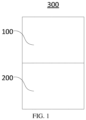
- FIG. 1 is a structural schematic view of an electronic atomization device according to an embodiment of the present disclosure.
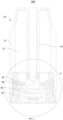
- FIG. 2 is a cross-section structural schematic view of an atomizer in the electronic atomization device shown in FIG. 1 .
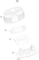
- FIG. 3 is an exploded schematic view of the atomizer in the electronic atomization device shown in FIG. 1 .
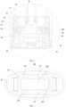
- FIG. 4 is an enlarged schematic view of a region A of the atomizer shown in FIG. 2 .
- the electronic atomization device 300 may be configured to atomize e-liquid.
- the electronic atomization device 300 includes an atomizer 100 and a body assembly 200 that are connected to each other.
- the atomizer 100 is configured to store the e-liquid and atomize the e-liquid to form the aerosol that can be inhaled by a user.
- the body assembly 200 is configured to supply power to the atomizer 100, so that the atomizer 100 may atomize the e-liquid to form the aerosol.
- the atomizer 100 generally includes an atomization sleeve 10, a mounting base 20, an atomization core 30, a seal member 40, and a base 50.
- the atomization sleeve 10 includes a liquid storage cavity body 11, the liquid storage cavity body 11 defines a liquid storage cavity 12.
- the atomization sleeve 10 further includes a vent tube 14 provided inside, the liquid storage cavity 12 is configured to store the e-liquid, and the vent tube 14 is configured to guide the aerosol to the mouth of the user.
- the mounting base 20 includes a housing 21 and a partition plate 22 arranged in the housing 21.
- the partition plate 22 defines a through hole 220, and the through hole 220 is in fluidly communication with the liquid storage cavity body 11, that is, the through hole 220 is in fluidly communication with the liquid storage cavity 12.
- the partition plate 22 divides a space in the housing 21 into a liquid inlet cavity 23 and an access cavity 24.
- the liquid inlet cavity 23 is in fluidly communication with the access cavity 24 through the partition plate 22, and the housing 21 further defines an aerosol outlet 25 on a same side as the liquid inlet cavity 23.
- the mounting base 20 is embedded in the atomization sleeve 10, and the vent tube 14 is connected to the aerosol outlet 25, so as to guide the aerosol to the mouth of the user through the aerosol outlet 25 and the vent tube 14.
- the partition plate 22 may be connected to the end of the housing 21 facing the liquid storage cavity body 11, so that the partition plate 22 is not required to define the liquid inlet cavity 23 with the housing 21.
- the partition plate 22 is connected to the end of the housing 21 facing away from the liquid storage cavity body 11, so that the partition plate 22 is not required to define the access cavity 24 with the housing 21.
- the present disclosure does not limit a specific structure of the mounting base 20, and the following matching relationship between the mounting base 20, the atomization core 30, and the seal member 40 is applicable to various deformed structures of the mounting base 20.
- the mounting base 20 may not be embedded in the atomization sleeve 10, as long as the through hole 220 is in fluidly communication with the liquid storage cavity body 11.
- the liquid storage cavity body 11 is a flexible liquid storage tank, a liquid storage ball, or the like.
- the liquid storage cavity body 11 is connected to the partition plate 22, and the liquid storage cavity 12 is in fluidly communication with the through hole 220.
- the partition plate 22 may be a plate body with a through hole 220 in a middle portion, or a plate member with a plurality of through holes 220 in the middle portion. It is allowed as long as the through hole 220 on the partition plate 22 is in fluidly communication with the liquid storage cavity body 11, which is not limited in the present disclosure.
- the atomization core 30 is assembled in the access cavity 24 and blocks the liquid inlet cavity 23.
- the atomization core 30 is in fluidly communication with the liquid inlet cavity 23, and a liquid storage space is defined by the atomization sleeve 10, the mounting base 20, and the atomization core 30.
- the liquid storage space stores the e-liquid, and the liquid inlet cavity 23 and the through hole 220 guide the e-liquid to the atomization core 30.
- the atomization core 30 atomizes the e-liquid to form the aerosol, and then the aerosol is guided to the mouth of the user through the aerosol outlet 25 and the vent tube 14.
- the seal member 40 is arranged on the side of the partition plate 22 facing away from the liquid storage cavity body 11 and is arranged between the partition plate 22 and the atomization core 30.
- the atomization core 30 abuts against the seal member 40 at the top of the atomization core 30, to prevent the e-liquid from leaking.
- the seal member 40 includes an opening 42 in fluidly communication with the through hole 220. Therefore, the opening 42 is in fluidly communication with the liquid storage cavity body 11, and the e-liquid enters the atomization core 30 through the opening 42.
- the base 50 is connected to and covers the end of the mounting base 20 facing away from the atomization sleeve 10.
- the base 50 abuts against the atomization core 30 to cause the atomization core 30 to abut against the seal member 40, and a space defined by the mounting base 20, the atomization core 30, and the base 50 forms the atomization cavity 51.
- the atomization core 30 atomizes the e-liquid and forms the aerosol in the atomization cavity 51, and the atomization cavity 51 is in fluidly communication with the aerosol outlet 25.
- An electrode is further connected in the base 50, and the electrode is electrically connected to the atomization core 30 to supply power to the atomization core 30.
- a vent hole 53 is defined on a bottom wall of the base 50 facing away from the mounting base 20, and the vent hole 53 is in fluidly communication with the atomization cavity 51.
- the atomization cavity 51 is fluidly communicated with the external air by the vent hole 53.
- the user inhales the electronic atomization device 300, and the atomization core 30 atomizes the e-liquid.
- the external air enters the atomization cavity 51 through the vent hole 53, and carries the aerosol in the atomization cavity 51 to flow through the aerosol outlet 25 and the vent tube 14 and arrive at the mouth of the user.
- a vent groove 26 is defined between the mounting base 20 and the seal member 40, and the liquid storage cavity body 11 is fluidly communicated with the external air by the vent groove 26. After the e-liquid is stored in the liquid storage space, the e-liquid seals the vent groove 26.
- the atomization cavity 51 is fluidly communicated with the liquid storage cavity 12 by the vent groove 26, and the liquid storage cavity 12 is further fluidly communicated with the external air through the atomization cavity 51.
- the atomization sleeve 10 defines a through hole, the through hole is fluidly communicated with the liquid storage cavity 12 by the vent groove 26, and the through hole is in fluidly communication with the external air.
- the air pressure in the liquid storage cavity 12 continues to be reduced.
- the air pressure in the cavity is reduced to a certain extent, the e-liquid does not flow smoothly.
- the atomization core 30 is prone to produce a burnt smell and the efficiency of generating the aerosol is reduced, which ultimately brings a poor inhaling experience to the user.
- the atomization core 30 atomizes the e-liquid, the air in the liquid storage cavity 12 is heated, and the air pressure in the cavity is increased. Excessively high air pressure in the liquid storage cavity causes the e-liquid to leak out from each connection portion. These factors greatly reduce the quality of the electronic atomization device 300.
- the vent groove 26 is defined between the mounting base 20 and the seal member 40, and the liquid storage cavity 12 is fluidly communicated with the external air by the vent groove 26.
- a dynamic balance is achieved among the air pressure, hydraulic pressure, and the capillary tension and resistance exerted by the vent groove 26 on the e-liquid in the liquid storage cavity 12 and the external air pressure by adjusting the e-liquid stored in the vent groove 26.
- a possibility of poor liquid flow and liquid leakage of the atomizer 100 may be reduced, and the quality of the atomizer 100 is improved.
- the air pressure in the liquid storage cavity 12 when the air pressure in the liquid storage cavity 12 is reduced and reaches a negative pressure threshold, the external air may enter the liquid storage cavity 12 through the vent groove 26 to implement ventilation, which have the air pressure in the liquid storage cavity 12 increase. As a result, the possibility of the poor liquid flow due to extremely low air pressure in the cavity is reduced, and the quality of the atomizer 100 is improved.
- the air pressure in the liquid storage cavity 12 is increased due to being heated to increase the temperature, the amount of e-liquid entering the vent groove 26 is increased. Therefore, the air pressure in the liquid storage cavity 12 may be appropriately reduced to avoid the occurrence of liquid leakage, and the quality of the atomizer 100 is also improved.
- the vent groove 26 is defined on the side of the partition plate 22 facing away from the liquid storage cavity body 11, and the vent groove 26 is covered by the seal member 40 and only a vent opening is exposed to be in fluidly communication with the through hole 220, and the air inlet is exposed to be in fluidly communication with the atomization cavity 51.
- vent grooves 26 are all defined on the side of the partition plate 22 facing away from the liquid storage cavity body 11, the e-liquid in the vent grooves 26 has the same hydraulic value. Therefore, the risk of liquid leakage due to the excessively high hydraulic value of the e-liquid in the vent grooves 26 may be reduced.
- the vent groove 26 may be defined in a detour manner on the partition plate 22 so as to increase a length and increase a space for storing the e-liquid.
- the vent groove 26 may also be defined in a straight line, as long as the through hole 220 is fluidly communicated with the external air by the vent groove 26, which is not limited in the present disclosure.
- the vent grooves 26 may also be multiple, and the multiple vent grooves 26 may be simultaneously ventilated to increase the air pressure in the liquid storage cavity 12, and the multiple vent grooves 26 may also be simultaneously fed with liquid, so as to reduce the air pressure in the liquid storage cavity 12. Therefore, the multiple vent grooves 26 may increase the convenience of adjusting the air pressure in the liquid storage cavity 12, so that the air pressure in the liquid storage cavity 12 may be quickly adjusted.
- the vent groove 26 may also be one, and the number of the vent grooves 26 is not limited in the present disclosure.
- a buffer groove 27 is further defined on the side of the partition plate 22 facing away from the liquid storage cavity 12.
- the vent groove 26 extends through the buffer groove 27.
- a cross-section area of the buffer groove 27 in a path direction of the vent groove 26 is greater than a cross-section area of the vent groove 26 in the same direction with the path direction of the vent groove, and the seal member 40 covers both the vent groove 26 and the buffer groove 27 to prevent liquid leakage at the vent groove 26 and the buffer groove 27.
- the buffer groove 27 is configured to store the e-liquid, and the cross-section area of the buffer groove 27 in the path direction of the vent groove 26 is greater than the cross-section area of the vent groove 26 in the same direction with the path direction of the vent groove. Therefore, the liquid storage capacity of the vent groove 26 may be improved, so as to avoid leakage of the e-liquid from the vent groove 26.
- a depth of the vent groove 26 should be set ranging from 0.1 mm to 0.5 mm
- a width of the vent groove 26 in a direction perpendicular to the path direction of the vent groove 26 should be set ranging from 0.1 mm to 0.5 mm
- a width of the buffer groove 27 is greater than the width of the vent groove 26
- a depth of the buffer groove 27 is greater than or equal to the depth of the vent groove 26.
- sealing is performed on an end surface through pressing the seal member 40 by the atomization core 30, so that the e-liquid can only flow from the vent groove 26.
- a structure that the vent groove 26 is defined on the side of the partition plate 22 facing away from the liquid storage cavity body 11 is taken as a research object, and a simulation analysis is performed for a size relationship between squeeze deformation of the seal member 40 and the width of the vent groove 26.
- the capillary tension exerted by the vent groove 26 on the e-liquid is too large, which causes the ventilation to be difficult, and is not conducive to adjust the air pressure in the liquid storage cavity 12.
- the width of the vent groove 26 is gradually increased from 0.1 mm to 0.5 mm, the squeeze deformation of the seal member 40 at a position corresponding to the vent groove 26 are gradually increased.
- the vent groove 26 When the depth of the vent groove 26 is greater than 0.5 mm or the width of the vent groove 26 is greater than 0.5 mm, the capillary tension exerted by the vent groove 26 on the e-liquid is too small, and the vent groove 26 is prone to the liquid leakage. In addition, when the seal member 40 covers the vent groove 26, a space of the seal member 40 deforming and squeezing the vent groove 26 is too large, and there is a risk of blocking the vent groove 26, which is not conducive to adjust the air pressure in the liquid storage cavity 12.
- the depth of the vent groove 26 ranges from 0.1 mm to 0.5 mm, and the width of the vent groove 26 ranges from 0.1 mm to 0.5 mm, which can not only ensure the appropriate capillary tension exerted by the vent groove 26 on the e-liquid, but also prevent the seal member 40 from blocking the vent groove 26. Therefore, it is conducive to adjust the air pressure of the liquid storage cavity 12 through the vent groove 26 and the buffer groove 27, so as to avoid the occurrence of liquid leakage and poor liquid flow of the atomizer 100.
- the partition plate 22 defines a through hole 220, and the liquid storage cavity 12 is fluidly communicated with the atomization core 30 by the through hole 220.
- the partition plate 22 defines two vent grooves 26, the two vent grooves 26 are defined around the through hole 220 of the partition plate 22, and a head end of any of the two vent grooves 26 is adjacent to a tail end of the other one of the two vent grooves 26, and the two vent grooves 26 have the same length.
- an air inlet of one of the two vent grooves 26 is adjacent to a vent opening of the other one of the two vent groove 26, and a vent opening of the one vent groove 26 is adjacent to an air inlet of the other vent groove 26.
- the two vent grooves 26 are defined around the through hole 220, the vent opening is in fluidly communication with the liquid storage cavity 12, and the air inlet is in fluidly communication with the external air. Therefore, the vent groove 26 may have a greater length, more e-liquid may be stored, and the air pressure in the liquid storage cavity 12 may also be easily adjusted.
- the vent openings of the two vent grooves 26 are defined at different positions, which may prevent bubbles generated at the vent openings defined at the same portion from being aggregated to increase the difficulty in the liquid flow of the e-liquid.
- the length and cross-section area of the vent groove 26 and the length and cross-section area of the buffer groove 27 may be set according to a specification of the atomizer 100, so as to adjust the air pressure in the liquid storage cavity 12.
- the seal member 40 includes a seal ring gasket 41 and two isolation gaskets 43 arranged on two opposite ends of the seal ring gasket 41, respectively.
- the seal ring gasket 41 defines the opening 42
- the isolation gasket 43 abuts against the housing 21, and an air inlet of the vent groove 26 is exposed from the seal ring gasket 41 and is misaligned with the isolation gasket 43.
- the air inlet of the vent groove 26 is in fluidly communication with the atomization cavity 51, and further may be in fluidly communication with the external air.
- the vent groove 26 is defined on the housing 21 arranged on the side of the partition plate 22 facing away from the liquid storage cavity body 11.
- the vent opening of the vent groove 26 is defined on the partition plate 22 to be in fluidly communication with the liquid storage cavity 12.
- the seal member 40 covers the vent groove 26, and the air inlet of the vent groove 26 is in fluidly communication with the external air.
- the buffer groove 27 may also be defined on a path of the vent groove 26, and the vent groove 26 flows through the buffer groove 27. Descriptions for the specifications and sizes of the vent groove 26 and the buffer groove 27 in the foregoing embodiments are also applicable to this embodiment, and are not repeated herein.
- the seal member 40 defines a vent groove 26.
- the vent groove 26 is defined on the side of the seal member 40 facing the partition plate 22 and/or the side of the seal member 40 facing the atomization core 30.
- the vent groove 26 may further be defined in the seal member 40.
- a six vent groove 26 is defined on the side of the seal member 40 facing the partition plate 22 and/or the side of the seal member 40 facing the atomization core 30. In this way, the air pressure in the liquid storage cavity 12 may be extremely easily adjusted.
- the seal member 40 has a greater deformation by being squeezed.
- the vent groove 26 is defined on the seal member 40, and the vent groove 26 is easily cut off due to the seal member 40 being squeezed and deformed.
- the ventilation effect of the vent groove 26 being defined on the seal member 40 is relatively poor.
- the ventilation effect may be poor for a part of vent grooves 26 have greater deformations by being squeezed, the liquid leakage may be easier to happen for another part of vent grooves 26 have less deformations by being squeezed. Therefore, generally, performances of a solution in which the vent groove 26 is defined on the partition plate 22 are better than performances of a solution in which the vent groove 26 is defined on the seal member 40.
- a vent groove 26 is defined on the side of the partition plate 22 facing away from the liquid storage cavity 12, and the seal member 40 also defines a vent groove 26.
- a vent groove 26 is defined on the side of the partition plate 22 facing away from the liquid inlet cavity 23
- another vent groove 26 is defined on the side of the seal member 40 facing the partition plate 22, and the two vent grooves 26 are defined at different positions. In this way, the number of vent grooves 26 allowed to be defined may be effectively increased, thereby increasing the convenience of adjusting the air pressure in the liquid storage cavity 12 and avoiding liquid leakage.
- the two vent grooves 26 are defined in alignment, thereby reducing groove the depth of the vent groove 26 defined in the partition plate 22 and the depth of the vent groove 26 defined in the seal member 40, which may effectively ensure that the partition plate 22 does not lose too much damage on the strength due to arranging the vent grooves 26.
- a sum of the groove depths of the two vent grooves 26 defined in alignment ranges from 0.1 mm to 0.5 mm.
- vent grooves 26 may further be defined on the side of the seal member 40 facing away from the partition plate 22.
- a vent groove 26 is defined on the side of the seal member 40 facing the partition plate 22 and another vent groove 26 is defined on the side of the seal member 40 facing the atomization core 30.
- the vent grooves 26 may further be defined in the seal member 40, which is not limited in the present disclosure.
- the present disclosure discloses an atomizer and an electronic atomization device.
- the vent groove is defined between the mounting base and the seal member, and the liquid storage cavity body is fluidly communicated with the external air by the vent groove.
- the external air may enter the liquid storage cavity body through the vent groove, thereby increasing the air pressure in the liquid storage cavity body, so as to avoid the possibility of poor liquid flow due to the extremely low air pressure in the cavity, and the quality of the atomizer is improved.
Landscapes
- Special Spraying Apparatus (AREA)
- Filling Or Discharging Of Gas Storage Vessels (AREA)
Abstract
Description
- The present disclosure relates to the technical field of atomizers, and in particular to an atomizer and an electronic atomization device.
- In the related art, an electronic atomization device mainly includes an atomizer and a body assembly. The atomizer generally includes a liquid storage cavity and an atomization assembly. The liquid storage cavity is configured to store an atomizable medium, and the atomization assembly is configured to heat and atomize the atomizable medium to form an aerosol that can be inhaled by an inhaler; and the body assembly is configured to supply power to the atomizer.
- When the atomizer atomizes the atomizable medium, the atomizable medium is consumed at a fast speed, and an air pressure of the liquid storage cavity is reduced, which results in poor liquid supply to the atomization assembly, so that the atomizable medium fails to be quickly supplemented to the atomization assembly. As a result, the atomization assembly dry burns and is overheated, such that the atomization assembly is destroyed due to the poor liquid supply, and further generates a burnt smell and harmful substances.
- The present disclosure provides an atomizer and an electronic atomization device.
- An atomizer is set out as in appended
claims 1 to 9. - An electronic atomization device is set out as in appended
claim 10. - To describe the technical solutions in the embodiments of the present disclosure or the embodiments of the related art more clearly, the following briefly describes the accompanying drawings required for describing the embodiments or the related art. Apparently, the accompanying drawings in the following descriptions show merely some embodiments of the present disclosure, and one of ordinary skill in the art may still derive other drawings from the accompanying drawings without creative efforts.
-
FIG. 1 is a structural schematic view of an electronic atomization device according to an embodiment of the present disclosure. -
FIG. 2 is a cross-section structural schematic view of an atomizer in the electronic atomization device shown inFIG. 1 . -
FIG. 3 is an exploded schematic view of the atomizer in the electronic atomization device shown inFIG. 1 . -
FIG. 4 is an enlarged schematic view of a region A of the atomizer shown inFIG. 2 . -
FIG. 5 is a structural schematic bottom view of a mounting base of the atomizer shown inFIG. 4 . -
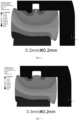
FIG. 6 is a schematic diagram of simulation analyzing a case of providing a vent groove and a seal member in a first specification on a partition plate shown inFIG. 5 . -
FIG. 7 is a schematic diagram of simulation analyzing a case of providing a vent groove and a seal member in a second specification on a partition plate shown inFIG. 5 . -
FIG. 8 is a schematic diagram of simulation analyzing a case of providing a vent groove and a seal member in a third specification on a partition plate shown inFIG. 5 . -
FIG. 9 is a schematic diagram of simulation analyzing a case of providing a vent groove and a seal member in a fourth specification on a partition plate shown inFIG. 5 . -
FIG. 10 is a structural schematic view of a seal member of the atomizer shown inFIG. 4 . -
FIG. 11 is another structural schematic view of the seal member of the atomizer shown inFIG. 4 . - The technical solutions in the embodiments of the present disclosure are clearly and completely described in the following with reference to the accompanying drawings in the embodiments of the present disclosure. Apparently, the described embodiments are merely some rather than all of the embodiments of the present disclosure. All other embodiments obtained by a person skilled in the art based on the embodiments of the present disclosure without creative efforts shall fall within the protection scope of the present disclosure.
- In the embodiments of the present disclosure, the terms "first", "second" and "third" are used merely for the purpose of description, and shall not be construed as indicating or implying relative importance or implying the numbers of indicated technical features. Therefore, features defining "first" "second" and "third" can explicitly or implicitly include at least one of the features. In the descriptions of the present disclosure, "more" means at least two, such as two or three unless it is specifically defined otherwise. In addition, the terms "include", "have", and any variant thereof are intended to cover a non-exclusive inclusion. For example, a process, a method, a system, a product, or a device that includes a series of steps or units is not limited to the listed steps or units; and instead, further optionally includes a step or unit that is not listed, or further optionally includes another step or unit that is intrinsic to the process, the method, the product, or the device.
- "Embodiment" mentioned in the specification means that particular features, structures, or characteristics described with reference to the embodiment may be included in at least one embodiment of the present disclosure. The term appearing at different positions of the specification may not refer to the same embodiment or an independent or alternative embodiment that is mutually exclusive with another embodiment. A person skilled in the art explicitly or implicitly understands that the embodiments described in the specification may be combined with other embodiments.
- The present disclosure provides an
electronic atomization device 300. As shown inFIG. 1 to FIG. 4 ,FIG. 1 is a structural schematic view of an electronic atomization device according to an embodiment of the present disclosure.FIG. 2 is a cross-section structural schematic view of an atomizer in the electronic atomization device shown inFIG. 1 .FIG. 3 is an exploded schematic view of the atomizer in the electronic atomization device shown inFIG. 1 .FIG. 4 is an enlarged schematic view of a region A of the atomizer shown inFIG. 2 . - The
electronic atomization device 300 may be configured to atomize e-liquid. Theelectronic atomization device 300 includes anatomizer 100 and abody assembly 200 that are connected to each other. Theatomizer 100 is configured to store the e-liquid and atomize the e-liquid to form the aerosol that can be inhaled by a user. Thebody assembly 200 is configured to supply power to theatomizer 100, so that theatomizer 100 may atomize the e-liquid to form the aerosol. - As shown in
FIG. 2 , theatomizer 100 generally includes anatomization sleeve 10, amounting base 20, anatomization core 30, aseal member 40, and abase 50. - The
atomization sleeve 10 includes a liquidstorage cavity body 11, the liquidstorage cavity body 11 defines aliquid storage cavity 12. Theatomization sleeve 10 further includes avent tube 14 provided inside, theliquid storage cavity 12 is configured to store the e-liquid, and thevent tube 14 is configured to guide the aerosol to the mouth of the user. - As shown in
FIG. 2 andFIG. 4 , themounting base 20 includes ahousing 21 and apartition plate 22 arranged in thehousing 21. Thepartition plate 22 defines a throughhole 220, and thethrough hole 220 is in fluidly communication with the liquidstorage cavity body 11, that is, thethrough hole 220 is in fluidly communication with theliquid storage cavity 12. - In this embodiment, the
partition plate 22 divides a space in thehousing 21 into aliquid inlet cavity 23 and anaccess cavity 24. Theliquid inlet cavity 23 is in fluidly communication with theaccess cavity 24 through thepartition plate 22, and thehousing 21 further defines anaerosol outlet 25 on a same side as theliquid inlet cavity 23. Themounting base 20 is embedded in theatomization sleeve 10, and thevent tube 14 is connected to theaerosol outlet 25, so as to guide the aerosol to the mouth of the user through theaerosol outlet 25 and thevent tube 14. - In another embodiment, the
partition plate 22 may be connected to the end of thehousing 21 facing the liquidstorage cavity body 11, so that thepartition plate 22 is not required to define theliquid inlet cavity 23 with thehousing 21. Alternatively, thepartition plate 22 is connected to the end of thehousing 21 facing away from the liquidstorage cavity body 11, so that thepartition plate 22 is not required to define theaccess cavity 24 with thehousing 21. The present disclosure does not limit a specific structure of themounting base 20, and the following matching relationship between themounting base 20, theatomization core 30, and theseal member 40 is applicable to various deformed structures of themounting base 20. - In another embodiment, the
mounting base 20 may not be embedded in theatomization sleeve 10, as long as the throughhole 220 is in fluidly communication with the liquidstorage cavity body 11. For example, the liquidstorage cavity body 11 is a flexible liquid storage tank, a liquid storage ball, or the like. The liquidstorage cavity body 11 is connected to thepartition plate 22, and theliquid storage cavity 12 is in fluidly communication with thethrough hole 220. - The
partition plate 22 may be a plate body with a throughhole 220 in a middle portion, or a plate member with a plurality of throughholes 220 in the middle portion. It is allowed as long as the throughhole 220 on thepartition plate 22 is in fluidly communication with the liquidstorage cavity body 11, which is not limited in the present disclosure. - As shown in
FIG. 2 andFIG. 4 , theatomization core 30 is assembled in theaccess cavity 24 and blocks theliquid inlet cavity 23. Theatomization core 30 is in fluidly communication with theliquid inlet cavity 23, and a liquid storage space is defined by theatomization sleeve 10, themounting base 20, and theatomization core 30. The liquid storage space stores the e-liquid, and theliquid inlet cavity 23 and the throughhole 220 guide the e-liquid to theatomization core 30. In this way, theatomization core 30 atomizes the e-liquid to form the aerosol, and then the aerosol is guided to the mouth of the user through theaerosol outlet 25 and thevent tube 14. - The
seal member 40 is arranged on the side of thepartition plate 22 facing away from the liquidstorage cavity body 11 and is arranged between thepartition plate 22 and theatomization core 30. Theatomization core 30 abuts against theseal member 40 at the top of theatomization core 30, to prevent the e-liquid from leaking. Theseal member 40 includes anopening 42 in fluidly communication with the throughhole 220. Therefore, theopening 42 is in fluidly communication with the liquidstorage cavity body 11, and the e-liquid enters theatomization core 30 through theopening 42. - As shown in
FIG. 2 andFIG. 3 , thebase 50 is connected to and covers the end of the mountingbase 20 facing away from theatomization sleeve 10. In addition, thebase 50 abuts against theatomization core 30 to cause theatomization core 30 to abut against theseal member 40, and a space defined by the mountingbase 20, theatomization core 30, and the base 50 forms theatomization cavity 51. Theatomization core 30 atomizes the e-liquid and forms the aerosol in theatomization cavity 51, and theatomization cavity 51 is in fluidly communication with theaerosol outlet 25. - An electrode is further connected in the
base 50, and the electrode is electrically connected to theatomization core 30 to supply power to theatomization core 30. Avent hole 53 is defined on a bottom wall of the base 50 facing away from the mountingbase 20, and thevent hole 53 is in fluidly communication with theatomization cavity 51. Theatomization cavity 51 is fluidly communicated with the external air by thevent hole 53. - The user inhales the
electronic atomization device 300, and theatomization core 30 atomizes the e-liquid. In addition, as the user inhales, the external air enters theatomization cavity 51 through thevent hole 53, and carries the aerosol in theatomization cavity 51 to flow through theaerosol outlet 25 and thevent tube 14 and arrive at the mouth of the user. - In the present disclosure, as shown in
FIGS. 4 to 7 , avent groove 26 is defined between the mountingbase 20 and theseal member 40, and the liquidstorage cavity body 11 is fluidly communicated with the external air by thevent groove 26. After the e-liquid is stored in the liquid storage space, the e-liquid seals thevent groove 26. - The
atomization cavity 51 is fluidly communicated with theliquid storage cavity 12 by thevent groove 26, and theliquid storage cavity 12 is further fluidly communicated with the external air through theatomization cavity 51. Alternatively, theatomization sleeve 10 defines a through hole, the through hole is fluidly communicated with theliquid storage cavity 12 by thevent groove 26, and the through hole is in fluidly communication with the external air. - When the e-liquid in the
liquid storage cavity 12 is consumed, in a case no air is supplemented to theliquid storage cavity 12, the air pressure in theliquid storage cavity 12 continues to be reduced. When the air pressure in the cavity is reduced to a certain extent, the e-liquid does not flow smoothly. As a result, because of the lack of sufficient liquid supply, theatomization core 30 is prone to produce a burnt smell and the efficiency of generating the aerosol is reduced, which ultimately brings a poor inhaling experience to the user. Alternatively, when theatomization core 30 atomizes the e-liquid, the air in theliquid storage cavity 12 is heated, and the air pressure in the cavity is increased. Excessively high air pressure in the liquid storage cavity causes the e-liquid to leak out from each connection portion. These factors greatly reduce the quality of theelectronic atomization device 300. - Therefore, in the present disclosure, the
vent groove 26 is defined between the mountingbase 20 and theseal member 40, and theliquid storage cavity 12 is fluidly communicated with the external air by thevent groove 26. As a result, a dynamic balance is achieved among the air pressure, hydraulic pressure, and the capillary tension and resistance exerted by thevent groove 26 on the e-liquid in theliquid storage cavity 12 and the external air pressure by adjusting the e-liquid stored in thevent groove 26. In this way, a possibility of poor liquid flow and liquid leakage of theatomizer 100 may be reduced, and the quality of theatomizer 100 is improved. - Specifically, when the air pressure in the
liquid storage cavity 12 is reduced and reaches a negative pressure threshold, the external air may enter theliquid storage cavity 12 through thevent groove 26 to implement ventilation, which have the air pressure in theliquid storage cavity 12 increase. As a result, the possibility of the poor liquid flow due to extremely low air pressure in the cavity is reduced, and the quality of theatomizer 100 is improved. When the air pressure in theliquid storage cavity 12 is increased due to being heated to increase the temperature, the amount of e-liquid entering thevent groove 26 is increased. Therefore, the air pressure in theliquid storage cavity 12 may be appropriately reduced to avoid the occurrence of liquid leakage, and the quality of theatomizer 100 is also improved. - In an embodiment, as shown in
FIG. 5 , thevent groove 26 is defined on the side of thepartition plate 22 facing away from the liquidstorage cavity body 11, and thevent groove 26 is covered by theseal member 40 and only a vent opening is exposed to be in fluidly communication with the throughhole 220, and the air inlet is exposed to be in fluidly communication with theatomization cavity 51. - Because
vent grooves 26 are all defined on the side of thepartition plate 22 facing away from the liquidstorage cavity body 11, the e-liquid in thevent grooves 26 has the same hydraulic value. Therefore, the risk of liquid leakage due to the excessively high hydraulic value of the e-liquid in thevent grooves 26 may be reduced. - The
vent groove 26 may be defined in a detour manner on thepartition plate 22 so as to increase a length and increase a space for storing the e-liquid. Thevent groove 26 may also be defined in a straight line, as long as the throughhole 220 is fluidly communicated with the external air by thevent groove 26, which is not limited in the present disclosure. - The
vent grooves 26 may also be multiple, and themultiple vent grooves 26 may be simultaneously ventilated to increase the air pressure in theliquid storage cavity 12, and themultiple vent grooves 26 may also be simultaneously fed with liquid, so as to reduce the air pressure in theliquid storage cavity 12. Therefore, themultiple vent grooves 26 may increase the convenience of adjusting the air pressure in theliquid storage cavity 12, so that the air pressure in theliquid storage cavity 12 may be quickly adjusted. Thevent groove 26 may also be one, and the number of thevent grooves 26 is not limited in the present disclosure. - A
buffer groove 27 is further defined on the side of thepartition plate 22 facing away from theliquid storage cavity 12. Thevent groove 26 extends through thebuffer groove 27. A cross-section area of thebuffer groove 27 in a path direction of thevent groove 26 is greater than a cross-section area of thevent groove 26 in the same direction with the path direction of the vent groove, and theseal member 40 covers both thevent groove 26 and thebuffer groove 27 to prevent liquid leakage at thevent groove 26 and thebuffer groove 27. - The
buffer groove 27 is configured to store the e-liquid, and the cross-section area of thebuffer groove 27 in the path direction of thevent groove 26 is greater than the cross-section area of thevent groove 26 in the same direction with the path direction of the vent groove. Therefore, the liquid storage capacity of thevent groove 26 may be improved, so as to avoid leakage of the e-liquid from thevent groove 26. - After research, it is found that a depth of the
vent groove 26 should be set ranging from 0.1 mm to 0.5 mm, a width of thevent groove 26 in a direction perpendicular to the path direction of thevent groove 26 should be set ranging from 0.1 mm to 0.5 mm, a width of thebuffer groove 27 is greater than the width of thevent groove 26, and a depth of thebuffer groove 27 is greater than or equal to the depth of thevent groove 26. - As shown in
FIG. 6 to FIG. 9 , sealing is performed on an end surface through pressing theseal member 40 by theatomization core 30, so that the e-liquid can only flow from thevent groove 26. A structure that thevent groove 26 is defined on the side of thepartition plate 22 facing away from the liquidstorage cavity body 11 is taken as a research object, and a simulation analysis is performed for a size relationship between squeeze deformation of theseal member 40 and the width of thevent groove 26. - During the analysis, it is found that when the depth of the
vent groove 26 is less than 0.1 mm or the width of thevent groove 26 is less than 0.1 mm, the capillary tension exerted by thevent groove 26 on the e-liquid is too large, which causes the ventilation to be difficult, and is not conducive to adjust the air pressure in theliquid storage cavity 12. In a process in which the width of thevent groove 26 is gradually increased from 0.1 mm to 0.5 mm, the squeeze deformation of theseal member 40 at a position corresponding to thevent groove 26 are gradually increased. When the depth of thevent groove 26 is greater than 0.5 mm or the width of thevent groove 26 is greater than 0.5 mm, the capillary tension exerted by thevent groove 26 on the e-liquid is too small, and thevent groove 26 is prone to the liquid leakage. In addition, when theseal member 40 covers thevent groove 26, a space of theseal member 40 deforming and squeezing thevent groove 26 is too large, and there is a risk of blocking thevent groove 26, which is not conducive to adjust the air pressure in theliquid storage cavity 12. - Therefore, the depth of the
vent groove 26 ranges from 0.1 mm to 0.5 mm, and the width of thevent groove 26 ranges from 0.1 mm to 0.5 mm, which can not only ensure the appropriate capillary tension exerted by thevent groove 26 on the e-liquid, but also prevent theseal member 40 from blocking thevent groove 26. Therefore, it is conducive to adjust the air pressure of theliquid storage cavity 12 through thevent groove 26 and thebuffer groove 27, so as to avoid the occurrence of liquid leakage and poor liquid flow of theatomizer 100. - In this embodiment, the
partition plate 22 defines a throughhole 220, and theliquid storage cavity 12 is fluidly communicated with theatomization core 30 by the throughhole 220. Thepartition plate 22 defines twovent grooves 26, the twovent grooves 26 are defined around the throughhole 220 of thepartition plate 22, and a head end of any of the twovent grooves 26 is adjacent to a tail end of the other one of the twovent grooves 26, and the twovent grooves 26 have the same length. - Specifically, an air inlet of one of the two
vent grooves 26 is adjacent to a vent opening of the other one of the twovent groove 26, and a vent opening of the onevent groove 26 is adjacent to an air inlet of theother vent groove 26. The twovent grooves 26 are defined around the throughhole 220, the vent opening is in fluidly communication with theliquid storage cavity 12, and the air inlet is in fluidly communication with the external air. Therefore, thevent groove 26 may have a greater length, more e-liquid may be stored, and the air pressure in theliquid storage cavity 12 may also be easily adjusted. In an embodiment, the vent openings of the twovent grooves 26 are defined at different positions, which may prevent bubbles generated at the vent openings defined at the same portion from being aggregated to increase the difficulty in the liquid flow of the e-liquid. - The length and cross-section area of the
vent groove 26 and the length and cross-section area of thebuffer groove 27 may be set according to a specification of theatomizer 100, so as to adjust the air pressure in theliquid storage cavity 12. - In this embodiment, as shown in
FIG. 10 , theseal member 40 includes aseal ring gasket 41 and twoisolation gaskets 43 arranged on two opposite ends of theseal ring gasket 41, respectively. Theseal ring gasket 41 defines theopening 42, theisolation gasket 43 abuts against thehousing 21, and an air inlet of thevent groove 26 is exposed from theseal ring gasket 41 and is misaligned with theisolation gasket 43. In this way, the air inlet of thevent groove 26 is in fluidly communication with theatomization cavity 51, and further may be in fluidly communication with the external air. - In some other embodiments, the
vent groove 26 is defined on thehousing 21 arranged on the side of thepartition plate 22 facing away from the liquidstorage cavity body 11. The vent opening of thevent groove 26 is defined on thepartition plate 22 to be in fluidly communication with theliquid storage cavity 12. Theseal member 40 covers thevent groove 26, and the air inlet of thevent groove 26 is in fluidly communication with the external air. - The
buffer groove 27 may also be defined on a path of thevent groove 26, and thevent groove 26 flows through thebuffer groove 27. Descriptions for the specifications and sizes of thevent groove 26 and thebuffer groove 27 in the foregoing embodiments are also applicable to this embodiment, and are not repeated herein. - In another embodiment, as shown in
FIG. 11 , theseal member 40 defines avent groove 26. Specifically, thevent groove 26 is defined on the side of theseal member 40 facing thepartition plate 22 and/or the side of theseal member 40 facing theatomization core 30. Alternatively, thevent groove 26 may further be defined in theseal member 40. - For example, a six
vent groove 26 is defined on the side of theseal member 40 facing thepartition plate 22 and/or the side of theseal member 40 facing theatomization core 30. In this way, the air pressure in theliquid storage cavity 12 may be extremely easily adjusted. - As shown in
FIG. 5 to FIG. 9 andFIG. 11 , relatively speaking, theseal member 40 has a greater deformation by being squeezed. Thevent groove 26 is defined on theseal member 40, and thevent groove 26 is easily cut off due to theseal member 40 being squeezed and deformed. Compared with the ventilation effect of thevent groove 26 being defined on thepartition plate 22, the ventilation effect of thevent groove 26 being defined on theseal member 40 is relatively poor. In a case where the specification and the size of thevent groove 26 is required to be increased to improve the ventilation effect of thevent groove 26 being defined on theseal member 40, considering that non-uniform forces distribute at different positions in theseal member 40, the ventilation effect may be poor for a part ofvent grooves 26 have greater deformations by being squeezed, the liquid leakage may be easier to happen for another part ofvent grooves 26 have less deformations by being squeezed. Therefore, generally, performances of a solution in which thevent groove 26 is defined on thepartition plate 22 are better than performances of a solution in which thevent groove 26 is defined on theseal member 40. - In some embodiments, referring to
FIG. 4, FIG. 5 , andFIG. 11 , a vent groove 26is defined on the side of thepartition plate 22 facing away from theliquid storage cavity 12, and theseal member 40 also defines avent groove 26. For example, avent groove 26 is defined on the side of thepartition plate 22 facing away from theliquid inlet cavity 23, anothervent groove 26 is defined on the side of theseal member 40 facing thepartition plate 22, and the twovent grooves 26 are defined at different positions. In this way, the number ofvent grooves 26 allowed to be defined may be effectively increased, thereby increasing the convenience of adjusting the air pressure in theliquid storage cavity 12 and avoiding liquid leakage. Alternatively, the twovent grooves 26 are defined in alignment, thereby reducing groove the depth of thevent groove 26 defined in thepartition plate 22 and the depth of thevent groove 26 defined in theseal member 40, which may effectively ensure that thepartition plate 22 does not lose too much damage on the strength due to arranging thevent grooves 26. A sum of the groove depths of the twovent grooves 26 defined in alignment ranges from 0.1 mm to 0.5 mm. - In an embodiment, the
vent grooves 26 may further be defined on the side of theseal member 40 facing away from thepartition plate 22. In another embodiment, avent groove 26 is defined on the side of theseal member 40 facing thepartition plate 22 and anothervent groove 26 is defined on the side of theseal member 40 facing theatomization core 30. In a yet embodiment, thevent grooves 26 may further be defined in theseal member 40, which is not limited in the present disclosure. - Different from the situation in the related art, the present disclosure discloses an atomizer and an electronic atomization device. In the present disclosure, the vent groove is defined between the mounting base and the seal member, and the liquid storage cavity body is fluidly communicated with the external air by the vent groove. As a result, the dynamic balance is achieved among the air pressure, the hydraulic pressure, and the capillary tension and resistance exerted by the vent groove on the e-liquid in the liquid storage cavity body and the external air pressure by adjusting the e-liquid stored in the vent groove. In addition, when the air pressure in the liquid storage cavity body of the atomizer is too low, the external air may enter the liquid storage cavity body through the vent groove, thereby increasing the air pressure in the liquid storage cavity body, so as to avoid the possibility of poor liquid flow due to the extremely low air pressure in the cavity, and the quality of the atomizer is improved.
- The above descriptions are merely embodiments of the present disclosure, and the scope of the present disclosure is not limited thereto. All equivalent structure or process changes made according to the contents of this specification and accompanying drawings in the present disclosure or by directly or indirectly applying the present disclosure in other related technical fields shall fall within the scope of the present disclosure.
Claims (10)
- An atomizer, configured to atomize e-liquid, wherein the atomizer comprises:a liquid storage cavity, configured to store the e-liquid;a mounting base, comprising a housing and a partition plate arranged in the housing, wherein the partition plate defines a through hole, and the through hole is in fluidly communication with the liquid storage cavity;an atomization core, mounted in the mounting base and configured to heat and atomize the e-liquid; anda seal member, arranged between the partition plate and the atomization core, wherein the seal member defines an opening in fluidly communication with the through hole, and the opening is configured to allow the e-liquid to enter the atomization core;wherein a vent groove is defined between the mounting base and the seal member, and the liquid storage cavity is fluidly communicated with external air by the vent groove.
- The atomizer according to claim 1, wherein the vent groove is defined on the side of the partition plate facing away from the liquid storage cavity.
- The atomizer according to claim 2, wherein a buffer groove is further defined on the side of the partition plate facing away from the liquid storage cavity, the vent groove extends through the buffer groove, a cross-section area of the buffer groove in the path direction of the vent groove is greater than the cross-section area of the vent groove in the same direction with the path direction of the vent groove, and the seal member covers the vent groove and the buffer groove.
- The atomizer according to claim 3, wherein the depth of the vent groove ranges from 0.1 mm to 0.5 mm, the width of the vent groove in the direction perpendicular to the path direction ranges from 0.1 mm to 0.5 mm, the width of the buffer groove is greater than the width of the vent groove, and the depth of the buffer groove is greater than or equal to the depth of the vent groove.
- The atomizer according to claim 4, wherein two vent grooves (26) are defined on the partition plate, and the two vent grooves defined around the through hole, and a head end of any of the two vent grooves is adjacent to a tail end of the other one of the two vent grooves.
- The atomizer according to claim 2, wherein the seal member comprises:a seal ring gasket, defining the opening; andtwo isolation gaskets, arranged on two opposite ends of the seal ring gasket, respectively;wherein the isolation gaskets abut against the housing, and an air inlet of the vent groove is exposed from the seal ring gasket and is misaligned with the isolation gasket.
- The atomizer according to claim 1, wherein the vent groove is defined on the housing arranged on the side of the partition plate facing away from the liquid storage cavity, and a vent opening of the vent groove is defined on the partition plate.
- The atomizer according to claim 1 or 2, wherein the vent groove is defined on the side of the seal member facing the partition plate and/or the side of the seal member facing the atomization core.
- The atomizer according to any one of claims 1 to 8, further comprising:a base, connected to the mounting base, and abutting against the atomization core;wherein an atomization cavity is defined by the base, the atomization core, and the mounting base; the vent groove is in fluidly communication with the atomization cavity, a vent hole is defined on the bottom wall of the base facing away from the mounting base, and the atomization cavity is fluidly communicated with the external air by the vent hole.
- An electronic atomization device, comprising:a body assembly; andthe atomizer according to any one of claims 1 to 9;wherein the body assembly is connected to the atomizer and configured to supply power to the atomizer.
Applications Claiming Priority (1)
| Application Number | Priority Date | Filing Date | Title |
|---|---|---|---|
| PCT/CN2020/089825 WO2021226835A1 (en) | 2020-05-12 | 2020-05-12 | Atomizer and electronic atomization device |
Publications (2)
| Publication Number | Publication Date |
|---|---|
| EP4147582A1 true EP4147582A1 (en) | 2023-03-15 |
| EP4147582A4 EP4147582A4 (en) | 2023-07-05 |
Family
ID=78526114
Family Applications (1)
| Application Number | Title | Priority Date | Filing Date |
|---|---|---|---|
| EP20935600.5A Pending EP4147582A4 (en) | 2020-05-12 | 2020-05-12 | Atomizer and electronic atomization device |
Country Status (3)
| Country | Link |
|---|---|
| US (1) | US20230122358A1 (en) |
| EP (1) | EP4147582A4 (en) |
| WO (1) | WO2021226835A1 (en) |
Families Citing this family (3)
| Publication number | Priority date | Publication date | Assignee | Title |
|---|---|---|---|---|
| CN216147234U (en) * | 2021-08-09 | 2022-04-01 | 深圳麦克韦尔科技有限公司 | Atomization base, atomizer and electronic atomization device |
| CN114159605A (en) * | 2021-12-29 | 2022-03-11 | 安徽同净枫翎新材料科技有限公司 | Sterilizing water tank for AES (advanced encryption Standard) antibacterial protection channel |
| WO2023150945A1 (en) * | 2022-02-09 | 2023-08-17 | 深圳麦克韦尔科技有限公司 | Electronic atomization device |
Family Cites Families (15)
| Publication number | Priority date | Publication date | Assignee | Title |
|---|---|---|---|---|
| US3341185A (en) * | 1966-07-29 | 1967-09-12 | Sr Walter L Kennedy | Fuel injector |
| WO2014117397A1 (en) * | 2013-02-02 | 2014-08-07 | Liu Qiuming | Electronic cigarette |
| US9723876B2 (en) * | 2013-03-15 | 2017-08-08 | Altria Client Services Llc | Electronic smoking article |
| CN105764364B (en) * | 2013-11-25 | 2018-09-04 | 吉瑞高新科技股份有限公司 | Electronic cigarette and electronic cigarette assembly method |
| CN107708450B (en) * | 2015-08-31 | 2020-08-14 | 深圳瀚星翔科技有限公司 | Electronic cigarette |
| CN207040889U (en) * | 2017-04-19 | 2018-02-27 | 深圳市合元科技有限公司 | Electronic cigarette equilibrium air pressure atomizer |
| KR102074933B1 (en) * | 2017-05-11 | 2020-03-02 | 주식회사 케이티앤지 | Vaporizer and aerosol generating apparatus comprising the same |
| CN207897892U (en) * | 2018-01-27 | 2018-09-25 | 深圳市新宜康电子技术有限公司 | Negative pressure sheet type aerosol generating means |
| EP3847914B1 (en) * | 2018-09-05 | 2025-10-29 | Shenzhen Smoore Technology Limited | Atomizer and electronic atomization device |
| CN109007980B (en) * | 2018-09-05 | 2023-12-19 | 深圳麦克韦尔科技有限公司 | Atomization devices and electronic cigarettes |
| CN109452691B (en) * | 2018-11-29 | 2024-04-23 | 深圳麦克韦尔科技有限公司 | Atomizing device and electronic atomizing equipment |
| CN209498584U (en) * | 2018-12-26 | 2019-10-18 | 深圳市合元科技有限公司 | Vape atomizer and electronic cigarette |
| EP3984390B1 (en) * | 2019-06-17 | 2024-07-17 | Shenzhen Smoore Technology Limited | Atomizer |
| CN110313647A (en) * | 2019-07-30 | 2019-10-11 | 深圳雾芯科技有限公司 | A kind of atomising device |
| CN111011933B (en) * | 2019-12-26 | 2025-02-18 | 深圳麦克韦尔科技有限公司 | Electronic atomization device and atomizer thereof |
-
2020
- 2020-05-12 WO PCT/CN2020/089825 patent/WO2021226835A1/en not_active Ceased
- 2020-05-12 EP EP20935600.5A patent/EP4147582A4/en active Pending
-
2022
- 2022-11-11 US US17/985,468 patent/US20230122358A1/en active Pending
Also Published As
| Publication number | Publication date |
|---|---|
| EP4147582A4 (en) | 2023-07-05 |
| WO2021226835A1 (en) | 2021-11-18 |
| US20230122358A1 (en) | 2023-04-20 |
Similar Documents
| Publication | Publication Date | Title |
|---|---|---|
| CN111772236B (en) | Atomizer and electronic atomizing device | |
| CN221489081U (en) | Electronic atomization device and atomizer thereof | |
| CN114158774B (en) | Electronic atomization device and atomizer | |
| US20230122358A1 (en) | Atomizer and electronic atomization device | |
| CN212937910U (en) | Atomizer and electronic atomization device | |
| CN218650266U (en) | Atomizer and electronic atomization device | |
| CN115590254B (en) | Atomizing components, atomizers and aerosol generating devices | |
| CN216961503U (en) | Atomizing device and electronic cigarette having the same | |
| CN112826136A (en) | Electronic atomization device, atomizer and base thereof | |
| CN115119981A (en) | Electronic atomization device, atomizer and liquid storage assembly of atomizer | |
| US20240260666A1 (en) | Atomization core, atomizer, and electronic atomization device | |
| CN115944115B (en) | An electronic atomizing device and its atomizer | |
| CN211832828U (en) | Electronic atomization device and atomizer thereof | |
| CN214629859U (en) | Atomizer and electronic atomization device | |
| CN217771492U (en) | Atomizer | |
| CN216821785U (en) | Atomizing core and aerosol generating device | |
| CA3185524A1 (en) | Electronic vaporization device and vaporizer | |
| CN217184804U (en) | Atomizer and electronic atomization device | |
| CN115428991A (en) | Atomizer and electronic atomization device | |
| CN115177028A (en) | Electronic atomization device, atomizer and top cover assembly of atomizer | |
| CN220859448U (en) | Atomization components and atomization devices | |
| CN116264915A (en) | Atomization device and electronic cigarette having same | |
| CN219323170U (en) | Atomizer and electronic atomization device | |
| CN218418397U (en) | Electronic atomization device and atomizer thereof | |
| CN217771434U (en) | Electronic atomization device and atomizer |
Legal Events
| Date | Code | Title | Description |
|---|---|---|---|
| STAA | Information on the status of an ep patent application or granted ep patent |
Free format text: STATUS: THE INTERNATIONAL PUBLICATION HAS BEEN MADE |
|
| PUAI | Public reference made under article 153(3) epc to a published international application that has entered the european phase |
Free format text: ORIGINAL CODE: 0009012 |
|
| STAA | Information on the status of an ep patent application or granted ep patent |
Free format text: STATUS: REQUEST FOR EXAMINATION WAS MADE |
|
| 17P | Request for examination filed |
Effective date: 20221205 |
|
| AK | Designated contracting states |
Kind code of ref document: A1 Designated state(s): AL AT BE BG CH CY CZ DE DK EE ES FI FR GB GR HR HU IE IS IT LI LT LU LV MC MK MT NL NO PL PT RO RS SE SI SK SM TR |
|
| REG | Reference to a national code |
Ref country code: DE Ref legal event code: R079 Free format text: PREVIOUS MAIN CLASS: A24F0040100000 Ipc: A24F0040420000 |
|
| A4 | Supplementary search report drawn up and despatched |
Effective date: 20230607 |
|
| RIC1 | Information provided on ipc code assigned before grant |
Ipc: A24F 40/10 20200101ALN20230601BHEP Ipc: A24F 40/485 20200101ALI20230601BHEP Ipc: A24F 40/42 20200101AFI20230601BHEP |
|
| DAV | Request for validation of the european patent (deleted) | ||
| DAX | Request for extension of the european patent (deleted) | ||
| RAP3 | Party data changed (applicant data changed or rights of an application transferred) |
Owner name: SHENZHEN SMOORE TECHNOLOGY LIMITED |
|
| RAP3 | Party data changed (applicant data changed or rights of an application transferred) |
Owner name: SHENZHEN SMOORE TECHNOLOGY LIMITED |