EP4147562A1 - Method, control unit and control system for operating an agricultural harvester and agricultural harvester - Google Patents
Method, control unit and control system for operating an agricultural harvester and agricultural harvester Download PDFInfo
- Publication number
- EP4147562A1 EP4147562A1 EP22192690.0A EP22192690A EP4147562A1 EP 4147562 A1 EP4147562 A1 EP 4147562A1 EP 22192690 A EP22192690 A EP 22192690A EP 4147562 A1 EP4147562 A1 EP 4147562A1
- Authority
- EP
- European Patent Office
- Prior art keywords
- foreign body
- signal
- component
- harvesting machine
- body sensor
- Prior art date
- Legal status (The legal status is an assumption and is not a legal conclusion. Google has not performed a legal analysis and makes no representation as to the accuracy of the status listed.)
- Granted
Links
- 238000000034 method Methods 0.000 title claims abstract description 13
- 238000005259 measurement Methods 0.000 claims abstract description 40
- 238000003306 harvesting Methods 0.000 claims abstract description 35
- 238000001514 detection method Methods 0.000 claims abstract description 23
- 230000007547 defect Effects 0.000 claims abstract description 9
- 239000002184 metal Substances 0.000 claims description 7
- 240000008042 Zea mays Species 0.000 claims description 5
- 235000002017 Zea mays subsp mays Nutrition 0.000 claims description 5
- 239000004459 forage Substances 0.000 claims description 5
- 235000016383 Zea mays subsp huehuetenangensis Nutrition 0.000 claims description 4
- 235000009973 maize Nutrition 0.000 claims description 4
- 230000001939 inductive effect Effects 0.000 claims description 2
- 238000013024 troubleshooting Methods 0.000 description 4
- 238000010586 diagram Methods 0.000 description 3
- 230000001419 dependent effect Effects 0.000 description 2
- 238000009434 installation Methods 0.000 description 2
- 235000005824 Zea mays ssp. parviglumis Nutrition 0.000 description 1
- 235000005822 corn Nutrition 0.000 description 1
- 230000002950 deficient Effects 0.000 description 1
- 238000011161 development Methods 0.000 description 1
- 230000018109 developmental process Effects 0.000 description 1
- 238000011156 evaluation Methods 0.000 description 1
- 230000001771 impaired effect Effects 0.000 description 1
- 230000005389 magnetism Effects 0.000 description 1
- 210000000056 organ Anatomy 0.000 description 1
- 230000011218 segmentation Effects 0.000 description 1
Images

Classifications
-
- A—HUMAN NECESSITIES
- A01—AGRICULTURE; FORESTRY; ANIMAL HUSBANDRY; HUNTING; TRAPPING; FISHING
- A01D—HARVESTING; MOWING
- A01D43/00—Mowers combined with apparatus performing additional operations while mowing
- A01D43/08—Mowers combined with apparatus performing additional operations while mowing with means for cutting up the mown crop, e.g. forage harvesters
- A01D43/085—Control or measuring arrangements specially adapted therefor
-
- A—HUMAN NECESSITIES
- A01—AGRICULTURE; FORESTRY; ANIMAL HUSBANDRY; HUNTING; TRAPPING; FISHING
- A01D—HARVESTING; MOWING
- A01D75/00—Accessories for harvesters or mowers
- A01D75/18—Safety devices for parts of the machines
- A01D75/187—Removing foreign objects
-
- A—HUMAN NECESSITIES
- A01—AGRICULTURE; FORESTRY; ANIMAL HUSBANDRY; HUNTING; TRAPPING; FISHING
- A01D—HARVESTING; MOWING
- A01D41/00—Combines, i.e. harvesters or mowers combined with threshing devices
- A01D41/12—Details of combines
- A01D41/127—Control or measuring arrangements specially adapted for combines
-
- A—HUMAN NECESSITIES
- A01—AGRICULTURE; FORESTRY; ANIMAL HUSBANDRY; HUNTING; TRAPPING; FISHING
- A01F—PROCESSING OF HARVESTED PRODUCE; HAY OR STRAW PRESSES; DEVICES FOR STORING AGRICULTURAL OR HORTICULTURAL PRODUCE
- A01F29/00—Cutting apparatus specially adapted for cutting hay, straw or the like
- A01F29/09—Details
- A01F29/16—Safety devices, e.g. emergency brake arrangements
Definitions
- the invention relates to a method, a control device, a control system for operating an agricultural harvesting machine and an agricultural harvesting machine.
- DE 10 2011 014 245 A1 discloses an agricultural harvesting machine designed as a forage harvester with an attachment, which has a metal detector as a foreign body sensor. If a metal foreign object is detected in the harvested crop based on the measurement signal from the metal detector, a quick stop can be carried out in order to prevent the working units of the harvesting machine from being damaged by the foreign object.
- the operation of an agricultural harvesting machine with a foreign body sensor can be impaired in that, due to sources of interference, a measurement signal provided by the foreign body sensor causes the detection of the presence of a foreign body, although there is actually no foreign body in the harvested crop. This can mean that the harvesting machine can no longer be operated properly.
- sources of interference can be caused, for example, by a faulty repair or faulty spare parts installed in the harvesting machine. Troubleshooting such sources of interference is time-consuming and requires partial dismantling of the harvesting machine. There is a need to simplify troubleshooting for those sources of interference that trigger signal components in the measurement signal that erroneously cause the detection of the presence of a foreign body.
- the present invention is based on the object of creating a novel method, control unit and control system for operating an agricultural harvesting machine and an agricultural harvesting machine with such a control system.
- a measurement signal provided by the foreign body sensor is evaluated with the aid of a signal analysis in such a way that at least one component of the working unit is determined on the basis of the signal analysis, which has a defect that triggers a signal component in the measurement signal that erroneously causes the detection of the presence of a foreign body.
- the signal analysis is used to determine at least one component of the working unit that has a defect and thus a source of interference that triggers a signal component in the measurement signal that incorrectly detection of the presence of a foreign body.
- troubleshooting can be automated as far as possible, so that the respective source of interference can be identified and repaired or replaced within a short time.
- At least one frequency analysis in particular a frequency and amplitude analysis, is preferably used as the signal analysis.
- a frequency or a variable corresponding to the frequency and/or an amplitude or a variable corresponding to the amplitude and/or a duration or a variable corresponding to the duration of the respective signal component is determined, with the at least one component of the working unit being determined on the basis of these variables , which has the fault location and thus the source of interference, which triggers the respective signal component in the measurement signal, which incorrectly causes the detection of the presence of a foreign body.
- This procedure is particularly preferred.
- the respective component of the working assembly which has the fault location causing the incorrect detection of a foreign body and thus the source of interference can be reliably determined in a simple manner.
- the frequency of signal components of the same amplitude and/or the same time duration is determined in the measurement signal, with the component of the working unit being determined depending on the frequency of the signal components of the same amplitude and/or the same time duration, which has the respective fault location and thus the source of interference that is in the measurement signal triggers the particular signal component that erroneously causes the detection of the presence of a foreign body.
- the component of the working unit is determined depending on the frequency of the signal components of the same amplitude and/or the same time duration, which has the respective fault location and thus the source of interference that is in the measurement signal triggers the particular signal component that erroneously causes the detection of the presence of a foreign body.
- the controller is defined in claim 6, the control system is defined in claim 8 and the agricultural harvesting machine is defined in claim 10.
- the 1 shows an agricultural harvesting machine 1 designed as a forage harvester, which includes a working unit 2 .
- the working unit 2 has a header 3 designed as a maize header, a feed mechanism 4 and a chopping mechanism 5.
- Crop to be harvested is separated from a subsoil to be processed with the aid of mowing and conveying elements 6 of the maize header 3 and fed to the chopping unit 5 via a feed drum 7 of the feed mechanism 4 .
- the harvested crop is chopped up and conveyed in the direction of a discharge chute 9 via a conveyor device 8 arranged downstream of the chopping unit 5 .
- the chopped crop can be ejected in the direction of a transport vehicle via the spout 9 .
- the chopping unit 5 has a front pair of rollers 10 viewed in the direction of transport of the harvested crop and a rear pair of rollers 11 , both of which are positioned in front of a chopping drum 12 of the chopper unit 5 as viewed in the direction of transport of the crop.
- the front pair of rollers 10 includes a feed roller 13 and a transport roller 14.
- the rear pair of rollers 11 has a press roller 15 and another transport roller 16, which is also referred to as a smooth roller.
- the rollers 13, 14 and 15 of the roller pairs 10 and 11 carry conveyor slats 17.
- the chopping drum 12 carries chopping knives 18.
- a foreign body sensor 19 is installed in the working unit 2, in the exemplary embodiment shown in the region of the front pair of rollers 10 of the chopping unit 5, with which the presence of a foreign body in the harvested crop can be concluded.
- the foreign body sensor 19 is preferably arranged in the lower front transport roller 14 .
- This foreign body sensor 19 can be a capacitive foreign body sensor or an inductive foreign body sensor, preferably a metal detector.
- the working assembly 2 can be stopped quickly.
- the foreign body sensor 19 transmits a measurement signal to a control unit 20 of the agricultural harvesting machine 1, which evaluates the measurement signal from the foreign body sensor 19.
- a corresponding warning message can be displayed to a driver of the agricultural harvesting machine 1 in a display device 21 .
- the measurement signal provided by the foreign body sensor 19 is evaluated with the aid of a signal analysis, in such a way that at least one component of the working unit 2 is determined on the basis of the signal analysis, which has a defect and thus a source of interference, which triggers a signal component in the measurement signal that erroneously triggers the detection caused by the existence of a foreign body.
- the respective component can have a source of interference to which the foreign body sensor 19, which is preferably designed as a metal detector, responds and then detects a respective one in the measurement signal of the foreign body sensor 19 Triggers a signal component that erroneously causes the detection of the presence of a foreign body, although there is actually no foreign body in the harvested crop.
- the foreign body sensor 19 which is preferably designed as a metal detector
- troubleshooting for such defective components of the working unit 2 can be automated and therefore simplified in order to exchange such components and subsequently enable trouble-free operation of the agricultural harvesting machine 1 .
- At least a frequency analysis preferably a frequency and amplitude analysis, is used as the signal analysis.
- a frequency or a variable corresponding to the frequency and/or an amplitude or a variable corresponding to the amplitude and/or a time duration or signal width or a variable corresponding to the time duration or signal width of the respective signal component is determined. which is present in the measurement signal of foreign body sensor 19 and erroneously causes the detection of the presence of a foreign body, with the at least one component of working unit 2 being determined on the basis of these variables, which has the fault location and thus the source of interference that triggers the respective signal component in the measurement signal that erroneously causes the detection of the presence of a foreign body.
- the invention is based on the finding that all rotating components of the working unit 2 installed in the vicinity of the foreign body sensor 19, in particular the rollers 13, 14, 15 and 16 of the roller pairs 10 and 11 as well as the chopper drum 12, the feed drum 7 and the mowing - and conveying elements 6, have individual speeds, so that if there should be a fault in the area of these components, which triggers a respective signal component in the measurement signal, which incorrectly causes the detection of the presence of a foreign body, this signal component over the frequency or period duration or the time interval between the signal components can be reliably assigned to the respective component.
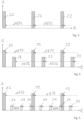
- the signal components 22 are present in the measurement signal S, which have an identical amplitude and identical signal width and have a defined period ⁇ t22. Based on the period ⁇ t22 or the frequency of the signal components 22 dependent thereon, that component of the working unit 2 can be determined which has a fault and thus a source of interference which causes the signal component 22 which erroneously causes the detection of the presence of a foreign body. This can be due to the defined speed of the components of the working unit 2, which differ from each other.
- a signal curve of the measurement signal S is plotted against time t, which in addition to the signal components 22 also has the signal components 23, the amplitude of the signal components 23 being smaller than the amplitude of the signal components 22.
- Both the signals 22 and the signals 23 have a defined period ⁇ t22 or ⁇ t23, where in 4 the period ⁇ t22 and ⁇ t23 are identical, so that both signal components 22, 23 can be assigned to the same component of the working unit 2, so that this component of the working unit 2 therefore has two fault points and therefore two sources of interference, which cause the detection of the presence of a foreign body.
- the signal component 24 is present, which differs from the signal component 22 in terms of both amplitude and signal width and period duration.
- the period ⁇ t24 of the signal component 24 is shorter than the period ⁇ t22 of the signal component 22, so that the two signal components 22, 24 have different frequencies and are therefore assigned to different components of the working unit 2.
- figure 5 is therefore closed on two components of the working unit 2, which have a fault or source of interference.
- the component of a working unit 2 of an agricultural harvesting machine 1 that has a fault and thus a source of interference that impairs the measurement signal of a foreign body sensor 19 can be determined easily and reliably.
- a fault or source of interference can be caused by a faulty repair or the installation of a faulty spare part, as a result of which the respective component then has residual magnetism, which influences the measurement signal of the foreign body sensor 19, which is preferably designed as a metal detector, and causes the faulty detection of the presence of a foreign body.
- the foreign body sensor 19 is segmented as seen in the transverse direction of the working unit 2, which runs perpendicular to the harvesting direction of the agricultural harvesting machine 1 and thus to the transport direction of the harvested crop, so that not only the component of the working unit 2 can be determined which has the respective fault location or source of interference , but also the axial position of this defect or source of interference can be determined in the determined component via the segmentation of the foreign body sensor.
- the spatial position of the fault location or source of interference can be narrowed down further in an automated manner.
- control unit 20 of agricultural harvesting machine 1 is set up to evaluate the measurement signal provided by foreign body sensor 19 with the aid of a signal analysis in such a way that at least one component of working unit 2 is determined on the basis of the signal analysis, which has a defect that triggers the signal component in the measurement signal that erroneously causing the detection of the presence of a foreign body. This has already been described in detail above.
- the invention relates to a control system of an agricultural harvesting machine, which includes the control unit 20 according to the invention and the foreign body sensor 19 , the foreign body sensor 19 sending a measurement signal to the control unit 20 .
- the invention relates to an agricultural harvesting machine 1 with a working unit 2 and a control system, as described above.
- the foreign body sensor 19 can be arranged in an attachment designed as a maize header, in the area of the chopping unit 5, in the area of a receiving element designed as a pick-up, or the like.
- the agricultural harvesting machine can be a forage harvester or a loading wagon.
Abstract
Verfahren zum Betreiben einer landwirtschaftlichen Erntemaschine (1), wobei die landwirtschaftliche Erntemaschine (1) ein Arbeitsaggregat (2) aufweist, in welchem ein Fremdkörpersensor (19) verbaut ist, wobei ein vom Fremdkörpersensor (19) bereitgestelltes Messsignal mit Hilfe eine Signalanalyse derart ausgewertet wird, dass auf Grundlage der Signalanalyse mindestens ein Bauteil des Arbeitsaggregats (2) ermittelt wird, welches eine Fehlerstelle aufweist, die im Messsignal einen Signalbestandteil auslöst, der fehlerhafterweise die Detektion des Vorliegens eines Fremdkörpers verursacht.

Description
Die Erfindung betrifft ein Verfahren, ein Steuergerät, ein Steuerungssystem zum Betreiben einer landwirtschaftlichen Erntemaschine und eine landwirtschaftliche Erntemaschine.The invention relates to a method, a control device, a control system for operating an agricultural harvesting machine and an agricultural harvesting machine.
Der Betrieb einer landwirtschaftlichen Erntemaschine mit einem Fremdkörpersensor kann dadurch beeinträchtigt werden, dass infolge von Störquellen ein vom Fremdkörpersensor bereitgestelltes Messsignal die Detektion des Vorliegens eines Fremdkörpers verursacht, obwohl sich tatsächlich kein Fremdkörper im Erntegut befindet. Dies kann dazu führen, dass die Erntemaschine nicht mehr ordnungsgemäß betrieben werden kann. Solche Störquellen können zum Beispiel durch eine fehlerhafte Reparatur oder fehlerhafte Ersatzteile, die in der Erntemaschine verbaut sind, verursacht werden. Die Fehlersuche nach solchen Störquellen ist zeitaufwendig und erfordert die teilweise Demontage der Erntemaschine. Es besteht Bedarf daran, die Fehlersuche nach solchen Störquellen, welche im Messsignal Signalbestandteile auslösen, die fehlerhafterweise die Detektion des Vorliegens eines Fremdkörpers verursachen, zu vereinfachen.The operation of an agricultural harvesting machine with a foreign body sensor can be impaired in that, due to sources of interference, a measurement signal provided by the foreign body sensor causes the detection of the presence of a foreign body, although there is actually no foreign body in the harvested crop. This can mean that the harvesting machine can no longer be operated properly. Such sources of interference can be caused, for example, by a faulty repair or faulty spare parts installed in the harvesting machine. Troubleshooting such sources of interference is time-consuming and requires partial dismantling of the harvesting machine. There is a need to simplify troubleshooting for those sources of interference that trigger signal components in the measurement signal that erroneously cause the detection of the presence of a foreign body.
Hiervon ausgehend liegt der vorliegenden Erfindung die Aufgabe zugrunde, ein neuartiges Verfahren, Steuergerät und Steuerungssystem zum Betreiben einer landwirtschaftlichen Erntemaschine und eine landwirtschaftliche Erntemaschine mit einem solchen Steuerungssystem zu schaffen.Proceeding from this, the present invention is based on the object of creating a novel method, control unit and control system for operating an agricultural harvesting machine and an agricultural harvesting machine with such a control system.
Diese Aufgabe wird durch ein Verfahren zum Betreiben einer landwirtschaftlichen Erntemaschine nach Patentanspruch 1 gelöst.This object is achieved by a method for operating an agricultural harvesting machine according to
Ein vom Fremdkörpersensor bereitgestelltes Messsignal wird mit Hilfe eine Signalanalyse derart ausgewertet, dass auf Grundlage der Signalanalyse mindestens ein Bauteil des Arbeitsaggregats ermittelt wird, welches eine Fehlerstelle aufweist, die im Messsignal einen Signalbestandteil auslöst, der fehlerhafterweise die Detektion des Vorliegens eines Fremdkörpers verursacht.A measurement signal provided by the foreign body sensor is evaluated with the aid of a signal analysis in such a way that at least one component of the working unit is determined on the basis of the signal analysis, which has a defect that triggers a signal component in the measurement signal that erroneously causes the detection of the presence of a foreign body.
Mithilfe der hier vorliegenden Erfindung wird erstmals vorgeschlagen, dass vom Fremdkörpersensor bereitgestellte Messsignal mit einer Signalanalyse derart auszuwerten, dass über die Signalanalyse mindestens ein Bauteil des Arbeitsaggregats ermittelt wird, welches eine Fehlerstelle und damit Störquelle aufweist, die im Messsignal einen Signalbestandteil auslöst, der fehlerhafterweise die Detektion des Vorliegens eines Fremdkörpers verursacht.With the help of the present invention, it is proposed for the first time to evaluate the measurement signal provided by the foreign body sensor with a signal analysis in such a way that the signal analysis is used to determine at least one component of the working unit that has a defect and thus a source of interference that triggers a signal component in the measurement signal that incorrectly detection of the presence of a foreign body.
Hierdurch kann die Fehlersuche weitestgehend automatisiert werden, sodass die jeweilige Störquelle innerhalb kurzer Zeit ermittelt und instandgesetzt oder ausgetauscht werden kann.As a result, troubleshooting can be automated as far as possible, so that the respective source of interference can be identified and repaired or replaced within a short time.
Vorzugsweise wird als Signalanalyse zumindest eine Frequenzanalyse, insbesondere eine Frequenz- und Amplitudenanalyse, genutzt. Insbesondere wird eine Frequenz oder eine der Frequenz entsprechende Größe und/oder eine Amplitude oder eine der Amplitude entsprechende Größe und/oder eine Zeitdauer oder eine der Zeitdauer entsprechende Größe des jeweiligen Signalbestandteils ermittelt, wobei auf Basis dieser Größen das mindestens eine Bauteil des Arbeitsaggregats ermittelt wird, welches die Fehlerstelle und damit die Störquelle aufweist, die im Messsignal den jeweiligen Signalbestandteil auslöst, der fehlerhafterweise die Detektion des Vorliegen eines Fremdkörpers verursacht. Diese Vorgehensweise ist besonders bevorzugt. Auf Grundlage der obigen Größen lässt sich das jeweilige Bauteil des Arbeitsaggregats, welches die die Fehldetektion eines Fremdkörpers verursachende Fehlerstelle und damit Störquelle aufweist, einfach zuverlässig ermitteln.At least one frequency analysis, in particular a frequency and amplitude analysis, is preferably used as the signal analysis. In particular, a frequency or a variable corresponding to the frequency and/or an amplitude or a variable corresponding to the amplitude and/or a duration or a variable corresponding to the duration of the respective signal component is determined, with the at least one component of the working unit being determined on the basis of these variables , which has the fault location and thus the source of interference, which triggers the respective signal component in the measurement signal, which incorrectly causes the detection of the presence of a foreign body. This procedure is particularly preferred. On the basis of the above variables, the respective component of the working assembly which has the fault location causing the incorrect detection of a foreign body and thus the source of interference can be reliably determined in a simple manner.
Vorzugsweise wird im Messsignal die Frequenz von Signalbestandteilen gleicher Amplitude und/oder gleicher Zeitdauer ermittelt, wobei abhängig von der Frequenz der Signalbestandteile gleicher Amplitude und/oder gleicher Zeitdauer dasjenige Bauteil des Arbeitsaggregats ermittelt wird, welches die jeweilige Fehlerstelle und damit Störquelle aufweist, die im Messsignal den jeweiligen Signalbestandteil auslöst, der fehlerhafterweise die Detektion des Vorliegens eines Fremdkörpers verursacht. Auch diese Merkmale sind besonders bevorzugt, um automatisiert das jeweilige Bauteil des Arbeitsaggregats zu ermitteln, welches die die Fehldetektion eines Fremdkörpers verursachende Fehlerstelle und damit Störquelle aufweist.Preferably, the frequency of signal components of the same amplitude and/or the same time duration is determined in the measurement signal, with the component of the working unit being determined depending on the frequency of the signal components of the same amplitude and/or the same time duration, which has the respective fault location and thus the source of interference that is in the measurement signal triggers the particular signal component that erroneously causes the detection of the presence of a foreign body. These features are also particularly preferred in order to automatically determine the respective component of the working unit which has the error location causing the incorrect detection of a foreign body and thus the source of interference.
Das Steuergerät ist in Patentanspruch 6, das Steuerungssystem ist in Patentanspruch 8 und die landwirtschaftliche Erntemaschine ist in Patentanspruch 10 definiert.The controller is defined in claim 6, the control system is defined in claim 8 and the agricultural harvesting machine is defined in
Bevorzugte Weiterbildungen der Erfindung ergeben sich aus den Unteransprüchen und der nachfolgenden Beschreibung. Ausführungsbeispiele der Erfindung werden, ohne hierauf beschränkt zu sein, an Hand der Zeichnung näher erläutert. Dabei zeigt:
- Fig. 1
- eine landwirtschaftliche Erntemaschine mit einem erfindungsgemäßen Steuergerät und Steuerungssystem;
- Fig. 2
- ein Detail der
Fig. 1 ; - Fig. 3
- ein Zeitdiagramm zur Verdeutlichung der Erfindung;
- Fig. 4
- ein weiteres Zeitdiagramm zur Verdeutlichung der Erfindung; und
- Fig. 5
- ein weiteres Zeitdiagramm zur Verdeutlichung der Erfindung.
- 1
- an agricultural harvesting machine with a controller and control system according to the invention;
- 2
- a detail of
1 ; - 3
- a timing diagram to illustrate the invention;
- 4
- another timing diagram to illustrate the invention; and
- figure 5
- another timing diagram to illustrate the invention.
Zu erntendes Erntegut wird mithilfe von Mäh- und Förderorganen 6 des Maisgebisses 3 von einem zu bearbeitenden Untergrund abgetrennt und über eine Einspeisetrommel 7 des Einspeisewerks 4 dem Häckselwerk 5 zugeführt.Crop to be harvested is separated from a subsoil to be processed with the aid of mowing and conveying elements 6 of the
Im Bereich des Häckselwerks 5 wird das Erntegut zerkleinert und über eine dem Häckselwerk 5 nachgeordnete Fördereinrichtung 8 in Richtung auf einen Auswurfkrümmer 9 gefördert. über den Auswurfkrümmer 9 kann das gehäckselte Erntegut in Richtung auf einen Transportwagen ausgeworfen werden.In the area of the
Das Häckselwerk 5 verfügt über ein in Transportrichtung des Ernteguts gesehen vorderes Walzenpaar 10 sowie ein hinteres Walzenpaar 11, die beide in Transportrichtung des Ernteguts gesehen vor einer Häckseltrommel 12 des Häckselwerks 5 positioniert sind. Das vordere Walzenpaar 10 umfasst eine Vorpresswalze 13 und eine Transportwalze 14. Das hintere Walzenpaar 11 verfügt über eine Presswalze 15 sowie eine weitere Transportwalze 16, die auch als Glattwalze bezeichnet wird. Die Walzen 13, 14 und 15 der Walzenpaare 10 und 11 tragen Förderleisten 17. Die Häckseltrommel 12 trägt Häckselmesser 18.The
Im Arbeitsaggregat 2, im gezeigten Ausführungsbeispiel im Bereich des vorderen Walzenpaars 10 des Häckselwerk 5, ist ein Fremdkörpersensor 19 verbaut, mit welchem auf das Vorliegen eines Fremdkörpers im geernteten Erntegut geschlossen werden kann. Der Fremdkörpersensor 19 ist vorzugsweise in der unteren vorderen Transportwalze 14 angeordnet.A
Bei diesem Fremdkörpersensor 19 kann es sich um einen kapazitiven Fremdkörpersensor oder einen induktiven Fremdkörpersensor handeln, vorzugsweise um einen Metalldetektor.This
Dann, wenn auf Grundlage des Messsignals des Fremdkörpersensors 19 ein Fremdkörper im Erntegut detektiert wird, kann ein Schnellstopp des Arbeitsaggregats 2 ausgeführt werden. Hierzu übermittelt der Fremdkörpersensor 19 ein Messsignal an ein Steuergerät 20 der landwirtschaftlichen Erntemaschine 1, welche das Messsignal des Fremdkörpersensors 19 auswertet. Abhängig von dieser Auswertung kann in einer Anzeigeeinrichtung 21 einem Fahrer der landwirtschaftlichen Erntemaschine 1 eine entsprechende Warnmeldung angezeigt werden.When a foreign body is detected in the harvested crop based on the measurement signal from the
Erfindungsgemäß wird das vom Fremdkörpersensor 19 bereitgestellte Messsignal mithilfe einer Signalanalyse ausgewertet, und zwar derart, dass auf Grundlage der Signalanalyse mindestens ein Bauteil des Arbeitsaggregats 2 ermittelt wird, welches eine Fehlerstelle und damit Störquelle aufweist, die im Messsignal einen Signalbestandteil auslöst, der fehlerhafterweise die Detektion der Existenz eines Fremdkörpers verursacht.According to the invention, the measurement signal provided by the
So kann zum Beispiel infolge einer fehlerhaften Reparatur oder des Einbaus eines fehlerhaften Ersatzteils für ein Bauteil des Arbeitsaggregats 2 das jeweilige Bauteil eine Störquelle aufweisen, auf die der Fremdkörpersensor 19, der vorzugsweise als Metalldetektor ausgeführt ist, anspricht und dann im Messsignal des Fremdkörpersensors 19 einen jeweiligen Signalbestandteil auslöst, der fehlerhafterweise die Detektion des Vorliegens eines Fremdkörpers verursacht, obwohl tatsächlich kein Fremdkörper im Erntegut vorliegt.For example, as a result of a faulty repair or the installation of a faulty spare part for a component of the working
Mit der Erfindung kann die Fehlersuche nach solchen fehlerhaften Bauteilen des Arbeitsaggregats 2 automatisiert und demnach vereinfacht werden, um solche Bauteile auszutauschen und nachfolgend einen störungsfreien Betrieb der landwirtschaftlichen Erntemaschine 1 zu ermöglichen.With the invention, troubleshooting for such defective components of the
Als Signalanalyse wird zumindest eine Frequenzanalyse, vorzugsweise eine Frequenz- und Amplitudenanalyse, genutzt.At least a frequency analysis, preferably a frequency and amplitude analysis, is used as the signal analysis.
Bei der Signalanalyse des Messsignals des Fremdkörpersensors 19 wird eine Frequenz oder eine der Frequenz entsprechende Größe und/oder eine Amplitude oder eine der Amplitude entsprechende Größe und/oder eine Zeitdauer bzw. Signalbreite oder eine der Zeitdauer bzw. Signalbreite entsprechende Größe des jeweiligen Signalbestandteils ermittelt, der im Messsignal des Fremdkörpersensors 19 vorliegt und fehlerhafterweise die Detektion des Vorliegens eines Fremdkörpers verursacht, wobei auf Basis dieser Größen das mindestens eine Bauteil des Arbeitsaggregats 2 ermittelt wird, welches die Fehlerstelle und damit Störquelle aufweist, die im Messsignal den jeweiligen Signalbestandteil auslöst, der fehlerhafterweise die Detektion des Vorliegens eines Fremdkörpers verursacht.During the signal analysis of the measurement signal of the
Dabei liegt der Erfindung die Erkenntnis zugrunde, dass sämtliche in der Nähe des Fremdkörpersensors 19 verbauten, rotierenden Bauteile des Arbeitsaggregats 2, insbesondere die Walzen 13, 14, 15 und 16 der Walzenpaare 10 und 11 sowie die Häckseltrommel 12, die Einspeisetrommel 7 und die Mäh- und Förderorgane 6, individuelle Drehzahlen aufweisen, sodass dann, wenn im Bereich dieser Bauteile eine Fehlerstelle vorhanden sein sollte, die im Messsignal einen jeweiligen Signalbestandteil auslöst, der fehlerhafterweise die Detektion des Vorliegens eines Fremdkörpers verursacht, dieser Signalbestandteil über die Frequenz bzw. Periodendauer oder den zeitlichen Abstand der Signalbestandteile zuverlässig dem jeweiligen Bauteil zugeordnet werden kann.The invention is based on the finding that all rotating components of the working
Es kann vorgesehen sein, dass im Messsignal die Frequenz von Signalbestandteilen gleicher Amplitude und/oder gleicher Zeitdauer ermittelt wird, wobei dann abhängig von der Frequenz der Signalbestandteile gleicher Amplitude und/oder gleicher Zeitdauer das Bauteil des Arbeitsaggregats 2 ermittelt wird, welches die jeweilige Fehlerstelle aufweist, die im Messsignal des Fremdkörpersensors 19 den jeweiligen Signalbestandteil auslöst, der fehlerhafterweise die Detektion des Vorliegens eines Fremdkörpers verursacht.Provision can be made for the frequency of signal components of the same amplitude and/or the same time duration to be determined in the measurement signal, with the component of the working
Weitere Details werden nachfolgend unter Bezugnahme auf
In
In
Im Signalverlauf S der
Mit der Erfindung kann einfach und zuverlässig das Bauteil eines Arbeitsaggregats 2 einer landwirtschaftlichen Erntemaschine 1 ermittelt werden, welches eine Fehlerstelle und damit Störquelle aufweist, welche das Messsignal eines Fremdkörpersensors 19 beeinträchtigt. Eine solche Fehlerstelle bzw. Störquelle kann durch eine fehlerhafte Reparatur oder den Verbau eines fehlerhaften Ersatzteils verursacht werden, wodurch dann das jeweilige Bauteil einen Restmagnetismus aufweist, welcher das Messsignal des vorzugsweise als Metalldetektor ausgebildeten Fremdkörpersensors 19 beeinflusst und die fehlerhafte Detektion des Vorliegens eines Fremdkörpers verursacht.With the invention, the component of a working
Mit der Erfindung ist es möglich, die landwirtschaftliche Erntemaschine 1 einfach innerhalb kurzer Zeit instand zu setzen, indem die ermittelte Fehlerquelle bzw. Störquelle am ermittelten Bauteil beseitigt wird.With the invention, it is possible to simply repair the
Typischerweise ist der Fremdkörpersensor 19 in Querrichtung des Arbeitsaggregats 2 gesehen, die senkrecht zur Ernterichtung der landwirtschaftlichen Erntemaschine 1 und damit Transportrichtung des Ernteguts verläuft, segmentiert, sodass dann nicht nur das Bauteil des Arbeitsaggregats 2 ermittelt werden kann, welches die jeweilige Fehlerstelle bzw. Störquelle aufweist, sondern auch die axiale Position dieser Fehlerstelle bzw. Störquelle in dem ermittelten Bauteil über die Segmentierung des Fremdkörpersensors ermittelt werden kann. Hierdurch lässt sich die räumliche Position der Fehlerstelle bzw. Störquelle weiter automatisiert eingrenzen.Typically, the
Die Erfindung betrifft weiterhin ein Steuergerät, welches eingerichtet ist, das oben beschriebene Verfahren automatisch auszuführen. So ist das Steuergerät 20 der landwirtschaftlichen Erntemaschine 1 eingerichtet, das vom Fremdkörpersensor 19 bereitgestellte Messsignal mithilfe einer Signalanalyse derart auszuwerten, dass auf Grundlage der Signalanalyse mindestens ein Bauteil des Arbeitsaggregats 2 ermittelt wird, welches eine Fehlerstelle aufweist, die im Messsignal den Signalbestandteil auslöst, der fehlerhafterweise die Detektion des Vorliegens eines Fremdkörpers verursacht. Dies wurde bereits oben im Detail beschrieben.The invention also relates to a control device which is set up to automatically carry out the method described above. For example,
Ferner betrifft die Erfindung ein Steuerungssystem einer landwirtschaftlichen Erntemaschine, welche das erfindungsgemäße Steuergerät 20 und den Fremdkörpersensor 19 umfasst, wobei der Fremdkörpersensor 19 ein Messsignal an das Steuergerät 20 sendet.Furthermore, the invention relates to a control system of an agricultural harvesting machine, which includes the
Ferner betrifft die Erfindung eine landwirtschaftliche Erntemaschine 1 mit einem Arbeitsaggregat 2 und einem Steuerungssystem, wie oben beschrieben. Der Fremdkörpersensor 19 kann dabei in einem als Maisgebiss ausgebildeten Vorsatzgerät, im Bereich des Häckselwerks 5, im Bereich eines als Pick-up ausgebildeten Aufnahmeorgans oder dergleichen angeordnet sein. Bei der landwirtschaftlichen Erntemaschine kann es sich um einen Feldhäcksler oder Ladewagen handeln.Furthermore, the invention relates to an
- 11
- landwirtschaftliche Erntemaschineagricultural harvester
- 22
- Arbeitsaggregatworking unit
- 33
- Maisgebisscorn header
- 44
- Einspeisewerkfeed station
- 55
- Häckselwerkshredder
- 66
- Mäh-und FörderorganMowing and conveying organ
- 77
- Einspeisetrommelfeed drum
- 88th
- Fördereinrichtungconveyor
- 99
- Auswurfkrümmerspout
- 1010
- Walzenpaarpair of rollers
- 1111
- Walzenpaarpair of rollers
- 1212
- Häckseltrommelchopper drum
- 1313
- Vorpresswalzefeed roller
- 1414
- Transportwalzetransport roller
- 1515
- Presswalzepress roller
- 1616
- Transportwalzetransport roller
- 1717
- Förderleiseconveyor quiet
- 1818
- Häckselmesserchopper knife
- 1919
- Fremdkörpersensorforeign body sensor
- 2020
- Steuergerätcontrol unit
- 2121
- Anzeigeeinrichtungdisplay device
- 2222
- Signalbestandteilsignal component
- 2323
- Signalbestandteilsignal component
- 2424
- Signalbestandteilsignal component
Claims (12)
Applications Claiming Priority (1)
| Application Number | Priority Date | Filing Date | Title |
|---|---|---|---|
| DE102021123418.2A DE102021123418A1 (en) | 2021-09-09 | 2021-09-09 | Method, controller and control system for operating an agricultural harvesting machine and agricultural harvesting machine |
Publications (2)
| Publication Number | Publication Date |
|---|---|
| EP4147562A1 true EP4147562A1 (en) | 2023-03-15 |
| EP4147562B1 EP4147562B1 (en) | 2023-10-25 |
Family
ID=83152137
Family Applications (1)
| Application Number | Title | Priority Date | Filing Date |
|---|---|---|---|
| EP22192690.0A Active EP4147562B1 (en) | 2021-09-09 | 2022-08-29 | Method, control unit and control system for operating an agricultural harvester and agricultural harvester |
Country Status (3)
| Country | Link |
|---|---|
| US (1) | US20230076800A1 (en) |
| EP (1) | EP4147562B1 (en) |
| DE (1) | DE102021123418A1 (en) |
Families Citing this family (1)
| Publication number | Priority date | Publication date | Assignee | Title |
|---|---|---|---|---|
| CN116897687B (en) * | 2023-07-19 | 2024-05-03 | 九方泰禾国际重工(青岛)股份有限公司 | Vertical header corn harvester |
Citations (6)
| Publication number | Priority date | Publication date | Assignee | Title |
|---|---|---|---|---|
| DE102005005736A1 (en) * | 2005-02-07 | 2006-09-28 | Claas Selbstfahrende Erntemaschinen Gmbh | Metal detection device |
| DE102006015152A1 (en) * | 2006-03-30 | 2008-09-25 | Claas Selbstfahrende Erntemaschinen Gmbh | Borne sound sensor unit |
| DE102008054488A1 (en) * | 2008-12-10 | 2010-06-17 | Deere & Company, Moline | Device for detecting foreign body invading in harvester, particularly field chopper, has vibration pick-up which is provided with conveying roller with roll shell rotatable against axis |
| DE102010024818A1 (en) * | 2009-06-24 | 2010-12-30 | Claas Saulgau Gmbh | Agricultural machine with a conveyor and a foreign body detector |
| DE102011014245A1 (en) | 2011-03-17 | 2012-09-20 | Claas Saulgau Gmbh | Method and device for operating a forage harvester |
| DE102017115465A1 (en) * | 2017-07-11 | 2019-01-17 | Claas Selbstfahrende Erntemaschinen Gmbh | Agricultural harvester, in particular forage harvester |
-
2021
- 2021-09-09 DE DE102021123418.2A patent/DE102021123418A1/en active Pending
-
2022
- 2022-08-25 US US17/895,777 patent/US20230076800A1/en active Pending
- 2022-08-29 EP EP22192690.0A patent/EP4147562B1/en active Active
Patent Citations (6)
| Publication number | Priority date | Publication date | Assignee | Title |
|---|---|---|---|---|
| DE102005005736A1 (en) * | 2005-02-07 | 2006-09-28 | Claas Selbstfahrende Erntemaschinen Gmbh | Metal detection device |
| DE102006015152A1 (en) * | 2006-03-30 | 2008-09-25 | Claas Selbstfahrende Erntemaschinen Gmbh | Borne sound sensor unit |
| DE102008054488A1 (en) * | 2008-12-10 | 2010-06-17 | Deere & Company, Moline | Device for detecting foreign body invading in harvester, particularly field chopper, has vibration pick-up which is provided with conveying roller with roll shell rotatable against axis |
| DE102010024818A1 (en) * | 2009-06-24 | 2010-12-30 | Claas Saulgau Gmbh | Agricultural machine with a conveyor and a foreign body detector |
| DE102011014245A1 (en) | 2011-03-17 | 2012-09-20 | Claas Saulgau Gmbh | Method and device for operating a forage harvester |
| DE102017115465A1 (en) * | 2017-07-11 | 2019-01-17 | Claas Selbstfahrende Erntemaschinen Gmbh | Agricultural harvester, in particular forage harvester |
Also Published As
| Publication number | Publication date |
|---|---|
| US20230076800A1 (en) | 2023-03-09 |
| DE102021123418A1 (en) | 2023-03-09 |
| EP4147562B1 (en) | 2023-10-25 |
Similar Documents
| Publication | Publication Date | Title |
|---|---|---|
| EP1564688B1 (en) | Monitoring system and device for monitoring the condition of a working machine | |
| DE10100522B4 (en) | Monitoring device for monitoring the function of a work machine | |
| DE19643997A1 (en) | Process for monitoring a conveyor belt and system for carrying out the process | |
| EP3527059B1 (en) | Combine harvester and method for the operation of same | |
| EP1187781B1 (en) | Device for monitoring a conveyor system | |
| EP4147562B1 (en) | Method, control unit and control system for operating an agricultural harvester and agricultural harvester | |
| EP3335541A1 (en) | Method for operating a cutting unit | |
| DE4302656C1 (en) | Function testing system for bottle inspection device - using evaluation of signals provided by identification device for different types of test bottles | |
| EP3704930B1 (en) | Agricultural harvester and method for operating an agricultural harvester | |
| BE1022629B1 (en) | Method and control system for operating a forage harvester and forage harvester | |
| DE3341071A1 (en) | Process and device for detecting metallic foreign bodies in the crop flow of a harvester | |
| EP3427570B1 (en) | Agricultural harvester, in particular chaff cutter | |
| DE102012205337A1 (en) | Self-propelled forage harvester for harvesting crop plants used as e.g. animal feed, has control unit that passes counter blades to second position far from first position relative to cutting drum, if crop situation does not exists | |
| EP1523876B1 (en) | Conveyor with a metal detecting device | |
| CH689583A5 (en) | A method for separating sheet sections, device for carrying and processing device with the same. | |
| EP2713701B1 (en) | Method and system | |
| WO2017016689A1 (en) | Conveying system | |
| EP3706546B1 (en) | Pick-up with metal detector | |
| EP4008171A1 (en) | Method for operating a combine harvester | |
| DE102016122802A1 (en) | Method for operating a vehicle washing system and vehicle washing system | |
| DE102015122305A1 (en) | Agricultural implement and method of operating the same | |
| DE102020125513A1 (en) | forage harvester | |
| EP3730909A2 (en) | Method and device for weighing a food portion with weight gradient identification | |
| EP3718391A1 (en) | Forage harvester | |
| BE1022979B1 (en) | Method and control device for operating a harvester |
Legal Events
| Date | Code | Title | Description |
|---|---|---|---|
| PUAI | Public reference made under article 153(3) epc to a published international application that has entered the european phase |
Free format text: ORIGINAL CODE: 0009012 |
|
| STAA | Information on the status of an ep patent application or granted ep patent |
Free format text: STATUS: THE APPLICATION HAS BEEN PUBLISHED |
|
| STAA | Information on the status of an ep patent application or granted ep patent |
Free format text: STATUS: REQUEST FOR EXAMINATION WAS MADE |
|
| AK | Designated contracting states |
Kind code of ref document: A1 Designated state(s): AL AT BE BG CH CY CZ DE DK EE ES FI FR GB GR HR HU IE IS IT LI LT LU LV MC MK MT NL NO PL PT RO RS SE SI SK SM TR |
|
| 17P | Request for examination filed |
Effective date: 20230222 |
|
| RBV | Designated contracting states (corrected) |
Designated state(s): AL AT BE BG CH CY CZ DE DK EE ES FI FR GB GR HR HU IE IS IT LI LT LU LV MC MK MT NL NO PL PT RO RS SE SI SK SM TR |
|
| GRAP | Despatch of communication of intention to grant a patent |
Free format text: ORIGINAL CODE: EPIDOSNIGR1 |
|
| STAA | Information on the status of an ep patent application or granted ep patent |
Free format text: STATUS: GRANT OF PATENT IS INTENDED |
|
| INTG | Intention to grant announced |
Effective date: 20230719 |
|
| P01 | Opt-out of the competence of the unified patent court (upc) registered |
Effective date: 20230724 |
|
| GRAS | Grant fee paid |
Free format text: ORIGINAL CODE: EPIDOSNIGR3 |
|
| GRAA | (expected) grant |
Free format text: ORIGINAL CODE: 0009210 |
|
| STAA | Information on the status of an ep patent application or granted ep patent |
Free format text: STATUS: THE PATENT HAS BEEN GRANTED |
|
| AK | Designated contracting states |
Kind code of ref document: B1 Designated state(s): AL AT BE BG CH CY CZ DE DK EE ES FI FR GB GR HR HU IE IS IT LI LT LU LV MC MK MT NL NO PL PT RO RS SE SI SK SM TR |
|
| REG | Reference to a national code |
Ref country code: GB Ref legal event code: FG4D Free format text: NOT ENGLISH |
|
| REG | Reference to a national code |
Ref country code: CH Ref legal event code: EP |
|
| REG | Reference to a national code |
Ref country code: DE Ref legal event code: R096 Ref document number: 502022000220 Country of ref document: DE |
|
| REG | Reference to a national code |
Ref country code: IE Ref legal event code: FG4D Free format text: LANGUAGE OF EP DOCUMENT: GERMAN |
|
| REG | Reference to a national code |
Ref country code: LT Ref legal event code: MG9D |
|
| REG | Reference to a national code |
Ref country code: NL Ref legal event code: MP Effective date: 20231025 |
|
| PG25 | Lapsed in a contracting state [announced via postgrant information from national office to epo] |
Ref country code: NL Free format text: LAPSE BECAUSE OF FAILURE TO SUBMIT A TRANSLATION OF THE DESCRIPTION OR TO PAY THE FEE WITHIN THE PRESCRIBED TIME-LIMIT Effective date: 20231025 |
|
| PG25 | Lapsed in a contracting state [announced via postgrant information from national office to epo] |
Ref country code: GR Free format text: LAPSE BECAUSE OF FAILURE TO SUBMIT A TRANSLATION OF THE DESCRIPTION OR TO PAY THE FEE WITHIN THE PRESCRIBED TIME-LIMIT Effective date: 20240126 |
|
| PG25 | Lapsed in a contracting state [announced via postgrant information from national office to epo] |
Ref country code: IS Free format text: LAPSE BECAUSE OF FAILURE TO SUBMIT A TRANSLATION OF THE DESCRIPTION OR TO PAY THE FEE WITHIN THE PRESCRIBED TIME-LIMIT Effective date: 20240225 |
|
| PG25 | Lapsed in a contracting state [announced via postgrant information from national office to epo] |
Ref country code: LT Free format text: LAPSE BECAUSE OF FAILURE TO SUBMIT A TRANSLATION OF THE DESCRIPTION OR TO PAY THE FEE WITHIN THE PRESCRIBED TIME-LIMIT Effective date: 20231025 |
|
| PG25 | Lapsed in a contracting state [announced via postgrant information from national office to epo] |
Ref country code: ES Free format text: LAPSE BECAUSE OF FAILURE TO SUBMIT A TRANSLATION OF THE DESCRIPTION OR TO PAY THE FEE WITHIN THE PRESCRIBED TIME-LIMIT Effective date: 20231025 |
|
| PG25 | Lapsed in a contracting state [announced via postgrant information from national office to epo] |
Ref country code: LT Free format text: LAPSE BECAUSE OF FAILURE TO SUBMIT A TRANSLATION OF THE DESCRIPTION OR TO PAY THE FEE WITHIN THE PRESCRIBED TIME-LIMIT Effective date: 20231025 Ref country code: IS Free format text: LAPSE BECAUSE OF FAILURE TO SUBMIT A TRANSLATION OF THE DESCRIPTION OR TO PAY THE FEE WITHIN THE PRESCRIBED TIME-LIMIT Effective date: 20240225 Ref country code: GR Free format text: LAPSE BECAUSE OF FAILURE TO SUBMIT A TRANSLATION OF THE DESCRIPTION OR TO PAY THE FEE WITHIN THE PRESCRIBED TIME-LIMIT Effective date: 20240126 Ref country code: ES Free format text: LAPSE BECAUSE OF FAILURE TO SUBMIT A TRANSLATION OF THE DESCRIPTION OR TO PAY THE FEE WITHIN THE PRESCRIBED TIME-LIMIT Effective date: 20231025 Ref country code: BG Free format text: LAPSE BECAUSE OF FAILURE TO SUBMIT A TRANSLATION OF THE DESCRIPTION OR TO PAY THE FEE WITHIN THE PRESCRIBED TIME-LIMIT Effective date: 20240125 Ref country code: PT Free format text: LAPSE BECAUSE OF FAILURE TO SUBMIT A TRANSLATION OF THE DESCRIPTION OR TO PAY THE FEE WITHIN THE PRESCRIBED TIME-LIMIT Effective date: 20240226 |