EP4147069B1 - Detektion und telemetrie durch impulse elektromagnetischer strahlung - Google Patents
Detektion und telemetrie durch impulse elektromagnetischer strahlung Download PDFInfo
- Publication number
- EP4147069B1 EP4147069B1 EP21731226.3A EP21731226A EP4147069B1 EP 4147069 B1 EP4147069 B1 EP 4147069B1 EP 21731226 A EP21731226 A EP 21731226A EP 4147069 B1 EP4147069 B1 EP 4147069B1
- Authority
- EP
- European Patent Office
- Prior art keywords
- pulse
- separation distance
- value
- radiation
- measurement signal
- Prior art date
- Legal status (The legal status is an assumption and is not a legal conclusion. Google has not performed a legal analysis and makes no representation as to the accuracy of the status listed.)
- Active
Links
Images

Classifications
-
- G—PHYSICS
- G01—MEASURING; TESTING
- G01S—RADIO DIRECTION-FINDING; RADIO NAVIGATION; DETERMINING DISTANCE OR VELOCITY BY USE OF RADIO WAVES; LOCATING OR PRESENCE-DETECTING BY USE OF THE REFLECTION OR RERADIATION OF RADIO WAVES; ANALOGOUS ARRANGEMENTS USING OTHER WAVES
- G01S17/00—Systems using the reflection or reradiation of electromagnetic waves other than radio waves, e.g. lidar systems
- G01S17/88—Lidar systems specially adapted for specific applications
- G01S17/95—Lidar systems specially adapted for specific applications for meteorological use
-
- G—PHYSICS
- G01—MEASURING; TESTING
- G01S—RADIO DIRECTION-FINDING; RADIO NAVIGATION; DETERMINING DISTANCE OR VELOCITY BY USE OF RADIO WAVES; LOCATING OR PRESENCE-DETECTING BY USE OF THE REFLECTION OR RERADIATION OF RADIO WAVES; ANALOGOUS ARRANGEMENTS USING OTHER WAVES
- G01S17/00—Systems using the reflection or reradiation of electromagnetic waves other than radio waves, e.g. lidar systems
- G01S17/02—Systems using the reflection of electromagnetic waves other than radio waves
- G01S17/06—Systems determining position data of a target
- G01S17/08—Systems determining position data of a target for measuring distance only
- G01S17/32—Systems determining position data of a target for measuring distance only using transmission of continuous waves, whether amplitude-, frequency-, or phase-modulated, or unmodulated
- G01S17/34—Systems determining position data of a target for measuring distance only using transmission of continuous waves, whether amplitude-, frequency-, or phase-modulated, or unmodulated using transmission of continuous, frequency-modulated waves while heterodyning the received signal, or a signal derived therefrom, with a locally-generated signal related to the contemporaneously transmitted signal
-
- G—PHYSICS
- G01—MEASURING; TESTING
- G01S—RADIO DIRECTION-FINDING; RADIO NAVIGATION; DETERMINING DISTANCE OR VELOCITY BY USE OF RADIO WAVES; LOCATING OR PRESENCE-DETECTING BY USE OF THE REFLECTION OR RERADIATION OF RADIO WAVES; ANALOGOUS ARRANGEMENTS USING OTHER WAVES
- G01S17/00—Systems using the reflection or reradiation of electromagnetic waves other than radio waves, e.g. lidar systems
- G01S17/02—Systems using the reflection of electromagnetic waves other than radio waves
- G01S17/50—Systems of measurement based on relative movement of target
- G01S17/58—Velocity or trajectory determination systems; Sense-of-movement determination systems
-
- G—PHYSICS
- G01—MEASURING; TESTING
- G01S—RADIO DIRECTION-FINDING; RADIO NAVIGATION; DETERMINING DISTANCE OR VELOCITY BY USE OF RADIO WAVES; LOCATING OR PRESENCE-DETECTING BY USE OF THE REFLECTION OR RERADIATION OF RADIO WAVES; ANALOGOUS ARRANGEMENTS USING OTHER WAVES
- G01S7/00—Details of systems according to groups G01S13/00, G01S15/00, G01S17/00
- G01S7/48—Details of systems according to groups G01S13/00, G01S15/00, G01S17/00 of systems according to group G01S17/00
- G01S7/483—Details of pulse systems
- G01S7/486—Receivers
- G01S7/4865—Time delay measurement, e.g. time-of-flight measurement, time of arrival measurement or determining the exact position of a peak
-
- G—PHYSICS
- G01—MEASURING; TESTING
- G01S—RADIO DIRECTION-FINDING; RADIO NAVIGATION; DETERMINING DISTANCE OR VELOCITY BY USE OF RADIO WAVES; LOCATING OR PRESENCE-DETECTING BY USE OF THE REFLECTION OR RERADIATION OF RADIO WAVES; ANALOGOUS ARRANGEMENTS USING OTHER WAVES
- G01S7/00—Details of systems according to groups G01S13/00, G01S15/00, G01S17/00
- G01S7/48—Details of systems according to groups G01S13/00, G01S15/00, G01S17/00 of systems according to group G01S17/00
- G01S7/491—Details of non-pulse systems
- G01S7/4912—Receivers
- G01S7/4917—Receivers superposing optical signals in a photodetector, e.g. optical heterodyne detection
-
- Y—GENERAL TAGGING OF NEW TECHNOLOGICAL DEVELOPMENTS; GENERAL TAGGING OF CROSS-SECTIONAL TECHNOLOGIES SPANNING OVER SEVERAL SECTIONS OF THE IPC; TECHNICAL SUBJECTS COVERED BY FORMER USPC CROSS-REFERENCE ART COLLECTIONS [XRACs] AND DIGESTS
- Y02—TECHNOLOGIES OR APPLICATIONS FOR MITIGATION OR ADAPTATION AGAINST CLIMATE CHANGE
- Y02A—TECHNOLOGIES FOR ADAPTATION TO CLIMATE CHANGE
- Y02A90/00—Technologies having an indirect contribution to adaptation to climate change
- Y02A90/10—Information and communication technologies [ICT] supporting adaptation to climate change, e.g. for weather forecasting or climate simulation
Definitions
- the present description relates to a method and a system for detection and ranging by pulses of electromagnetic radiation, in particular for carrying out anemometric measurements.
- Electromagnetic radiation pulse detection and ranging systems are used for many applications, including characterizing fluid flows.
- the radiation pulses are emitted towards an exploration zone which is likely to contain one or more targets to be characterized, and a part of each pulse which is backscattered or retroreflected by each target is detected in return by the system.
- the targets consist of backscattering particles which are present in suspension in the fluid, and which are driven in movement in accordance with the speed of the fluid at each location in the exploration zone.
- the targets consist of aerosol droplets, dust, ice grains, etc. which are suspended in the air.
- Such detection and ranging systems using pulses of electromagnetic radiation can be of the LIDAR type, for “Light Detection And Ranging” in English or detection and ranging by light, or of the RADAR type, for “Radio Detection And Ranging” in English.
- English or radio wave detection and ranging For LIDAR systems, the radiation emitted is of the laser type, with a frequency of this radiation which is commonly between 30 THz (Terahertz) and approximately 1200 THz, corresponding to a wavelength of between 250 nm (nanometer) and 10 ⁇ m (micrometer) approximately.
- the radio wave frequency used is commonly between 3 MHz (megahertz) and 300 GHz (gigahertz).
- High frequency RADAR systems correspond to radiation wavelengths that are between 1 mm (millimeter) and 7.5 mm, typically.
- an aim of the present invention is to improve the efficiency of measurements by detection and ranging with pulses of electromagnetic radiation. More particularly, the invention aims to improve spatial resolution and accuracy of the radial speed measurement results which are obtained for a continuous medium to be characterized, for example for a fluid flow to be characterized, in particular in a portion of atmosphere.
- Another object of the invention consists of taking into account the operation of the detection and telemetry system by pulses of electromagnetic radiation which is used, in order to reduce the quantity of calculations which are necessary to deduce, from a signal of measurement which is collected during an acquisition sequence, a measurement result which characterizes the targets contained in the exploration zone.
- the result of the method of the invention is constituted by a distribution of backscatter amplitude, and by a distribution of radial speed, the two distributions being functions of the distance of distance from the system used, at l inside the exploration zone.
- the backscatter amplitude distribution characterizes the concentration or type of targets that are present at locations variables in the exploration zone
- the radial speed distribution characterizes a movement of these targets in the same locations, this movement being able to vary between different locations within the exploration zone.
- the radial velocity distribution constitutes a characterization of the radial velocity field of the flow.
- the method of the invention is based on an addition of contributions from the spatial slices of the exploration zone to the measurement signal which is collected during an acquisition sequence by the system used.
- the method of the invention simultaneously takes into account the contributions of the spatial slices of decomposition of the exploration zone, and the effects of the operation of the system used.
- it takes into account the shape of the electromagnetic radiation pulses which are emitted during each acquisition sequence, as well as the detection mode and the signal processing which are applied within a detection channel of the system.
- the characteristics of the emission of radiation by the system used, the effects of propagation of the radiation between the system and the exploration zone, and in the exploration zone, for the two directions of outward and return of the radiation, the backscattering power which is effective locally in the exploration zone, and the detection and signal processing characteristics in the detection path of the system used, are all taken into account simultaneously in the method of the invention .
- the method of the invention is particularly effective in reducing the quantity of calculations which are implemented. This efficiency is provided by the use of the impulse response, which contains the characteristics of the radiation emission which is produced by the system used, and the detection and signal processing characteristics of this system.
- Step /4/ consists of carrying out through calculations an operation which is the inverse of this convolution, and sometimes called deconvolution.
- the characterization of the impulse response can be obtained in step /3/ by performing at least one acquisition sequence with the electromagnetic radiation pulse detection and ranging system, and with a single retroreflective element which is positioned at a determined separation distance in the exploration zone.
- step /3/ constitutes an experimental calibration of the system used.
- the characterization of the impulse response can be obtained by carrying out a digital simulation of an operation of the detection and ranging system by pulses of electromagnetic radiation when a single retroreflective element is present at a determined distance in the zone d 'exploration. In both cases, the characterization of the impulse response that is obtained may be imperfect.
- the characterization of the impulse response which is obtained can be affected by detection noise, by the effects of sampling and a digitization of values that can be implemented, etc.
- the impulse response of the system is characterized by numerical simulation, secondary physical phenomena may not be taken into account.
- the method of the invention is compatible with a detection and ranging system using pulses of electromagnetic radiation of the monostatic type or of the bistatic type.
- monostatic such a system for which optical output and detection ports of this system are combined, contiguous or close to each other in relation to the distance which exists between the system and the exploration zone.
- bistatic we mean a system for which the optical output and detection ports are spatially separated.
- the detection and ranging system using pulses of electromagnetic radiation which is used to implement the invention can be adapted to carry out measurements according to any detection modes.
- a detection mode can be used, where the frequency shift of the backscattered radiation, which is due to the Doppler effect occurring during the reflection or backscattering of the pulses emitted on a moving target(s), is measured by causing the backscattered radiation that is detected to interfere with itself.
- Such a detection mode is called “direct detection”.
- the system can be preferably adapted to implement a heterodyne detection mode, where the backscattered radiation which is detected is mixed with a reference wave, and a beat which results from this mixture is analyzed.
- the measurement signal which is produced at each acquisition sequence, and which is used in step /4/ is a heterodyne measurement signal.
- the electromagnetic radiation pulse detection and ranging system which is used to implement the invention can be RADAR type.
- the radiation of the pulses which are emitted by this system may have a wavelength in vacuum of between 1 mm and 7.5 mm.
- the measurement result can be deduced from the measurement signal in step /4/ by applying a two-dimensional decomposition algorithm which uses a maximum a posteriori type method, or a maximum likelihood method, which can be regularized, in this case also called penalized, or not, or even a stochastic method such as a Markov Chain Monte Carlo method.
- the method can then comprise an additional step which is executed from the measurement result provided by the two-dimensional decomposition algorithm, to reduce widths of radial velocity distributions which are separately assigned to several values of the separation distance in the exploration area.
- step /4/ comprises assigning a unique value of radial speed and a unique value of backscatter amplitude to each value of the separation distance, for a sampling of values of the separation distance within the exploration zone.
- a reconstruction of the measurement signal is then calculated as a sum of contributions each equal to the impulse response applied to a separation distance value and to the radial speed value which was assigned to this separation distance value, and multiplied by the backscatter amplitude value that was also assigned to the same separation distance value, for all separation distance values in the sampling.
- Such a system is adapted in particular to implement a method which conforms to the first aspect of the invention.
- the invention is now described, by way of example, for a pulsed LIDAR system with heterodyne detection.
- the invention can be easily transposed, from the description which follows, to detection modes other than heterodyne detection, and/or to a RADAR system.
- the invention relates to the conversion of a measurement signal into a measurement result which includes a radial velocity distribution as a function of a separation distance. Equivalently, each radial speed value can be replaced in this characterization by a frequency shift value which is produced by the Doppler effect, by a target which has the radial speed value.
- the LIDAR system which is described below is suitable for carrying out anemometric measurements, using backscattering of laser radiation which is produced by particles present suspended in the air.
- backscattering particles which constitute targets to be characterized and which can be aerosol droplets, dust or ice grains, are designated by the reference 100 in [ Fig. 1 ].
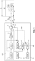
- the LIDAR system 10 includes a 10E transmission channel and a 10D detection channel.
- the emission path 10E comprises a laser source 1, which produces monochromatic radiation which can have a wavelength equal to 1545 nm (nanometer) when this radiation propagates in the air, at least one acousto-optic modulator 2, denoted MAO and controlled to form successive pulses from the laser radiation which is produced by the source 1, and an optical amplifier 3, denoted AMPL.
- the acousto-optic modulator 2 further produces a frequency shift of the laser radiation which is emitted by the LIDAR system 10 towards a target with respect to the laser radiation as produced by the source 1.
- the detection channel 10D includes a detector 7, denoted DETECT, and an acquisition card 8, denoted ACQ.
- the acquisition card 8 is connected to receive an analog electrical heterodyne detection signal which is produced by the detector 7, and which is denoted SD. It is designed to apply processing to this detection signal SD, and deliver a measurement signal which results from this processing, and which is denoted SM.
- the acquisition card 8 can perform functions of sampling and digitization of the detection signal SD, accumulation of the digitized signal for several identical radiation pulses which are emitted successively, filtering, etc.
- an electrical signal amplifier can be used on the transmission link of the detection signal SD between the detector 7 and the acquisition card 8.
- the detector 7 receives as input a mixture of the part of each pulse which was received by the detection channel 10D, with a part of the emission laser radiation which is taken between the source 1 and the acousto-optic modulator 2.
- the part of the radiation emission laser which is transmitted to the detector 7 from the emission channel 10E can undergo various intermediate transformations, between its sampling in the emission channel 10E and the detector 7.
- the acquisition 8 are controlled by a controller 9, which is denoted CTRL and provides the system with its LIDAR operation at each acquisition sequence.
- the emission channels 10E and detection channels 10D can be coupled by an optical circulator 4 to a port optical 5, the latter acting as both an optical output port for the transmission channel 10E and an optical reception port for the detection channel 10D.
- the transmission channel 10E is optically coupled to an optical input port 41 of the optical circulator 4
- the detection channel 10D is optically coupled to an optical output port 42 of the optical circulator 4
- the optical port 5 of the LIDAR system 10 is optically coupled to a mixed optical input-output port 43 of the optical circulator 4.
- Such a LIDAR 10 system is known to those skilled in the art. It makes it possible to analyze the content of an exploration zone ZE which is located on the path of the laser pulses in front of the optical port 5, outside the system 10. In known manner, this exploration zone ZE is an overlapping volume between a trace of propagation of the laser pulses beyond the optical port 5, and a medium to be characterized which is located outside the system 10.
- a distance d m which separates a proximal limit of the zone of exploration ZE of the optical port 5 can be defined by a detection time window which is applied by the detection channel 10D, in particular by the acquisition card 8.
- a length l e of the exploration zone ZE is also determined by the detection time window.
- the exploration zone ZE can be determined by a convergence which is applied to the laser pulses, for example by using a converging lens to form the optical port 5.
- each laser pulse has a pulse duration, which is denoted ⁇ in the following.
- the measurement signal SM contains a characterization of the targets 100 which are contained in the exploration zone ZE, in terms of distance of each target relative to the optical port 5, denoted d e , and speed radial of each target, denoted v r .
- the separation distance d e is counted from the proximal limit of the exploration zone ZE.
- radial speed v r of one of the targets 100 we mean its speed component which is parallel to the direction of propagation of the laser pulses. It is counted positively for a movement away from the target relative to system 10, and negatively for a movement closer to the target towards system 10.
- the targets 100 are constituted by droplets of aerosols, dust and/or ice grains which are suspended in the air, and which are driven in movement by air currents as they exist in the exploration zone ZE.
- a measurement which is carried out using the LIDAR 10 system then makes it possible to characterize the radial speed distribution v r of these air currents as a function of the distance d e , within the exploration zone ZE.
- a pulse of radiation which is designated by the reference P, is represented symbolically in [ Fig. 1 ], propagating between the optical port 5 of the system 10 and the exploration zone ZE.
- the invention which is the subject of the present description relates to the transformation of the measurement signal SM which is delivered by the acquisition card 8, into a measurement result RM which relates to the distribution of radial speed v r in the exploration zone ZE.
- This transformation can be carried out by a calculation unit 11, denoted CPU.
- the RM measurement result is constituted by a backscatter amplitude distribution, which is a function of both the separation distance d e and the radial velocity v r , or equivalently a function of the separation distance d e and the Doppler effect frequency shift ⁇ f.
- This backscatter amplitude distribution of the RM measurement result is denoted S(d e ,v r ), or S(d e , ⁇ f). It constitutes an estimate of a real distribution of backscatter amplitude S 0 (d e ,v r ), or S 0 (d e , ⁇ f), which is produced by the targets 100 in the exploration zone ZE.
- the reference 12 designates storage means, denoted STOR, which are accessible to the calculation unit 11.
- the structure of the storage means 12 can be advantageously selected to facilitate convolution calculations which use values stored in these means 12.
- FIG. 2 shows an example of a radiation pulse envelope, corresponding to the shape of each pulse P as produced by the emission path 10E of the system 10 and effective downstream of the optical port 5.
- the abscissa axis marks the time denoted t, and expressed in nanoseconds (ns), and the ordinate axis marks the instantaneous power of the radiation, denoted PW and normalized in relation to its maximum value.
- the width at half maximum of the pulse shown is approximately 75 ns, corresponding to a spatial length of approximately 22 m when the pulse propagates through the air outside of system 10.
- the impulse response can be obtained from the measurement signal SM, by restricting this signal within time windows which are progressively shifted in time, and by applying an apodization function, for example of Gaussian form, to each restriction. of the SM measurement signal in the corresponding time window.
- an apodization function aims to remove or attenuate discontinuities which are present in the analyzed signal, to remove or reduce artifacts which would be caused by these discontinuities.
- the ends of the time windows would cause sidelobes in subsequent Fourier transform results.
- the apodization function removes such lobes.
- Each portion of the SM measurement signal restricted to a time window, and apodized, is then processed by Fourier transformation with respect to time, then the result of this Fourier transformation is squared to provide a section with a constant value of the distance distance from e , from the representation of the impulse response of [ Fig. 3 ].
- the origin of the horizontal axis which marks the values of the separation distance d e can be assigned to that of these values which corresponds to the maximum of the impulse response.
- the horizontal axis marks deviation values ⁇ d e , defined in relation to this origin for the impulse response.
- each spectrum is therefore a function of the frequency difference ⁇ f, and is assigned to a value of the separation distance d e , and therefore to a value of the difference ⁇ d e , in accordance with the flight time between an instant of emission of the pulse and a middle instant of the time window which was applied to the SM measurement signal for this spectrum.
- the impulse response of the system 10 can be obtained experimentally, for example by actually placing a retroreflecting mirror at an identified location in the exploration zone ZE, and by giving this retroreflecting mirror a radial speed of movement which is also identified.
- the retroreflecting mirror can be stationary relative to the system 10 for such experimental determination of the impulse response.
- An acquisition sequence is then executed by the system 10, during which the calculation unit 11 applies the cutting and transformation operations which have just been described to the measurement signal SM as delivered by the acquisition card 8.
- the impulse response can be obtained by a digital simulation of the operation of the system 10 during an acquisition sequence, by simulating the effect of the retroreflecting mirror which is placed in the exploration zone ZE, on the radiation pulses issued.
- obtaining the impulse response constitutes a calibration of the system 10, to subsequently use this system 10 in order to carry out useful measurements.
- the impulse response which has been determined for the system 10 is stored in the storage means 12.
- the horizontal axis can therefore identify the deviation ⁇ d e in distance from the position of the retroreflective target which was used for the calibration. It is expressed in meters.
- the vertical axis marks the frequency shift ⁇ f, expressed in Megahertz, relative to a frequency of the radiation in the 10E emission channel.
- the third axis of the diagram of [ Fig. 3 ] identifies an amplitude of the impulse response, which can be expressed in an arbitrary unit (au). It corresponds to the level lines of the values indicated 0.1, 0.3, 0.6 and 1.0.
- the impulse response shows that the unique retroreflective target, because of the shape of each pulse and the signal processing which is applied in the detection channel 10D, appears in the measurement signal SM as a spread array of retroreflective targets, which are moving according to a radial speed distribution distributed around the actual value radial velocity of the single target.
- These spreads of the impulse response in terms of separation distance and radial speed are due in particular to the finite width of the pulse of [ Fig. 2 ], and to the detection time window which is applied by the acquisition card 8.
- the radial speed distribution depends on the deviation ⁇ d e in relation to the actual distance of the single target which has been used for the calibration of system 10, so that the impulse response is a function of the two variables ⁇ d e and v r , or equivalently ⁇ d e and ⁇ f.
- h( ⁇ d e , ⁇ f) designates this impulse response.
- the oblique stretching which affects the impulse response in the system of the ⁇ d e and ⁇ f axes reveals a drift of approximately 3 MHz in the frequency of each emitted pulse, between the beginning and the end of this pulse. Such a drift in the transmission frequency will thus be automatically taken into account in the processing to obtain the RM measurement result for a useful acquisition sequence, so that this drift does not introduce an error into this result.
- each spectrum is assigned to the value of the separation distance d e which corresponds to the flight time between the instant of emission of the pulse and the median instant of the time window that was applied to the SM measurement signal for this spectrum.
- the spectrogram is denoted Sp(d e , ⁇ f) by taking a reference frequency to define the frequency shift ⁇ f between each spectrum component and this reference frequency. In the case of heterodyne detection, this reference frequency is the frequency of the monochromatic radiation which is produced by the laser source 1.
- the spectrogram Sp(d e , ⁇ f) can be modeled by [S 0 *h](d e , ⁇ f), where S 0 (d e , ⁇ f) is again the backscatter amplitude distribution of the contents of the exploration zone ZE during the sequence of useful acquisition, and * denotes the two-dimensional convolution operation.
- the calculation unit 11 determines an estimate of the backscatter amplitude distribution S 0 (d e , ⁇ f) from the spectrogram Sp(d e , ⁇ f).
- This estimate of the backscatter amplitude distribution S 0 (d e , ⁇ f) can constitute the RM measurement result, and is denoted S(d e , ⁇ f).
- several algorithms can be used alternatively, including the following two which are cited as non-limiting examples.
- a two-dimensional decomposition algorithm Such an algorithm is applied to the spectrogram Sp(d e , ⁇ f) using the impulse response h( ⁇ d e , ⁇ f). It is commonly called a two-dimensional deconvolution algorithm, and can use a maximum likelihood method, which consists of minimization of a criterion of attachment to the data, also called cost function, such as for example a least squares criterion which measures the difference between the spectrogram Sp(d e , ⁇ f) and the modeling of this spectrogram in the form [S*h](d e , ⁇ f).
- a second possible method consists of adding to the data attachment criterion, a regularization criterion, also called penalization criterion, which contains a priori knowledge information of certain characteristics of the content of the exploration zone ZE. Such information may be, for example, that each spectrum has a very small spectral width.
- An example of a reference book on such a posteriori maximum method is “Bayesian Approach to Inverse Problems”, edited by J. Idier, ISTE / John Wiley, London, 2008, pp. 243-283 .
- a third still possible method can be a stochastic method, also called Monte Calo method, according to which the solution is sought by exploring a set of states which are possible for the content of the exploration zone ZE, according to 'at least one random characteristic.
- Such a Monte Carlo method is further said to be Markov chains when each new drawing of the random feature depends only on the result of the current drawing, without depending on the results of previous drawings.
- An example of a reference book on these stochastic methods is “Monte Carlo Statistical Methods”, by Christian Robert and George Casella, Springer-Verlag, coll. Springer Texts in Statistics, 2010 .
- the two-dimensional decomposition methods are known to those skilled in the art, so that it is not necessary to describe them further here.
- the result of the two-dimensional decomposition is the estimate S(d e , ⁇ f) of the backscatter amplitude distribution, which depends on the two variables of separation distance and frequency shift.
- This estimate S(d e , ⁇ f) can be improved by a complementary step which consists of reducing the width of the radial speed distribution v r , or of the frequency shift ⁇ f which is associated with v r by the Doppler effect, for each value of the separation distance d e .
- a maximum reduction can in particular be obtained by keeping for each value of the separation distance d e , only the value of the frequency shift ⁇ f - or the value of the radial speed v r - which corresponds to the maximum of the distribution of estimation S(d e , ⁇ f) as resulting from the two-dimensional decomposition algorithm.
- Another method of maximum reduction which is also possible consists of keeping for each value of the separation distance d e , only the value of the frequency shift ⁇ f which corresponds to the center of a peak of the estimation distribution S(d e , ⁇ f), as a function of the frequency shift ⁇ f and separately for each value of the separation distance d e .
- the center of peak can be determined from a section at mid-height of this peak, or from an adjustment (“fit” in English) of the peak by a model thereof.
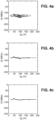
- FIG. 4a is a first three-dimensional diagram which represents the variations of the spectrogram Sp(d e , ⁇ f) as calculated from the measurement signal SM delivered by the acquisition card 8, for a useful acquisition sequence carried out with a flow d air in the ZE exploration zone.
- the horizontal axis of the diagram marks the separation distance d e , between 0 and 250 m.
- the vertical axis of the diagram marks the frequency shift ⁇ f, between -250 MHz and 0, and the third axis of the diagram, which is associated with the indicated level lines, marks the spectral amplitude values.
- This spectrogram has a significant width parallel to the frequency shift axis ⁇ f, for each value of the separation distance d e .
- [ Fig. 4b ] is a second three-dimensional diagram which represents the variations of the estimation distribution S(d e , ⁇ f) as resulting from the two-dimensional decomposition algorithm applied to the spectrum of [Fig. 1a].
- the values of S(d e , ⁇ f) are therefore identified by the third axis of the diagram, perpendicular to the axes of separation distance d e and frequency shift ⁇ f. For each value of the separation distance d e , the frequency shift width ⁇ f is significantly reduced.
- [ Fig. 4c ] is a third three-dimensional diagram which represents the variations of the estimation distribution S(d e , ⁇ f) after this distribution has been limited to its maximum value parallel to the frequency shift axis ⁇ f for each value of the distance d distance from e .
- This RM measurement result shows that the air moves closer to the system 10, locally in a first region corresponding to d e approximately equal to 45 m, and moves simultaneously in a second zone corresponding to d e approximately equal to 100 m but this time moving away from system 10.
- a sparse adjustment decomposition algorithm Such an algorithm consists of directly searching for the estimate of the backscatter amplitude distribution S 0 (d e , ⁇ f) in the form of a single value of frequency shift ⁇ f - or of a single value of radial speed v r - for each value of the separation distance d e in the exploration zone ZE. It then proceeds by iterative adjustments of these values ⁇ f(d e ), and of backscatter amplitude values which are also assigned one by one to the values of the separation distance d e .
- a threshold criterion can be applied to the difference between [S*h](d e , ⁇ f) and Sp(d e , ⁇ f).
- another possible criterion concerns a progression between successive iterations, the reduction of the gap between [S*h](d e , ⁇ f) and Sp(d e , ⁇ f).
- the system 10 can be mobile, for example with a variable orientation of the direction of emission of the laser pulses, in order to carry out a scan in the portion of atmosphere . Then, acquisition sequences are repeated, each time adopting a new orientation of the system 10.
Landscapes
- Physics & Mathematics (AREA)
- Engineering & Computer Science (AREA)
- Electromagnetism (AREA)
- Computer Networks & Wireless Communication (AREA)
- General Physics & Mathematics (AREA)
- Radar, Positioning & Navigation (AREA)
- Remote Sensing (AREA)
- Optical Radar Systems And Details Thereof (AREA)
- Measurement Of Radiation (AREA)
- Radar Systems Or Details Thereof (AREA)
Claims (12)
- Verfahren zur Erfassung und Telemetrie durch elektromagnetische Strahlungsimpulse, um eine radiale Geschwindigkeitsverteilung (vr) in Abhängigkeit von einem Entfernungsabstand (de) innerhalb einer Erkundungszone (ZE) zu charakterisieren, umfassend die folgenden Schritte:/1/ Erhalten eines Systems (10) zur Erfassung und Telemetrie durch elektromagnetische Strahlungsimpulse, welches dazu ausgebildet ist, während einer Erfassungssequenz wenigstens einen Impuls (P) einer elektromagnetischen Strahlung auszusenden, einen Teil des wenigstens einen Strahlungsimpulses zu erfassen, der von wenigstens einem Ziel (100), das sich in der Erkundungszone (ZE) befindet, rückgestreut wurde, und ein Messsignal (SM) zu erzeugen, das dem rückgestreuten und erfassten Teil des Strahlungsimpulses entspricht, wobei das Messsignal Informationen zu einem Entfernungsabstand (de) und eine Radialgeschwindigkeit (vr) jedes Ziels umfasst, wobei die Informationen zur Radialgeschwindigkeit jedes Ziels einer Frequenzverschiebung aufgrund eines Dopplereffekts entsprechen, der auftritt, wenn die Strahlung von dem Ziel rückgestreut wird ; und/2/ Durchführen einer Erfassungssequenz durch Steuern des Systems (10), um den wenigstens einen Impuls (P) in die Erkundungszone (ZE) zu senden, wobei das Verfahren dadurch gekennzeichnet ist, dass es ferner die folgenden zusätzlichen Schritte umfasst:/3/ Erhalten einer Charakterisierung einer Impulsantwort des Systems (10), wobei die Impulsantwort dem Messsignal (SM) entspricht, das von dem System (10) während einer Erfassungssequenz erzeugt wird, und wenn sich ein einzelnes Rückstreuelement in der Erkundungszone (ZE) befindet, wobei das einzelne Rückstreuelement einem einzelnen Wert des Entfernungsabstands (de) entspricht und einen bekannten Wert der Radialgeschwindigkeit (vr) in Bezug auf das System aufweist, und wenn die Erkundungszone kein anderes Rückstreuelement als das einzelne Rückstreuelement aufweist; und/4/ unter der Annahme, dass das Messsignal (SM), das in Schritt /2/ erzeugt wurde, eine Summe von Beiträgen ist, die jeweils der Impulsantwort entsprechen, die auf einen Wert des Entfernungsabstands (de) und einen Wert für die Radialgeschwindigkeit (vr) angewendet und mit einem Wert für die Rückstreuamplitude multipliziert wird, Erhalten eines Messergebnisses (RM) in Form von Paaren, die jeweils aus einem Wert für die Rückstreuamplitude und einem Wert für die Radialgeschwindigkeit bestehen und die jeweils mehreren Werten des Entfernungsabstands innerhalb der Erkundungszone zugeordnet werden, durch Zerlegung des Messsignals in mehrere Beiträge.
- Verfahren nach Anspruch 1, bei dem die Impulsantwort eine Funktion einerseits des Entfernungsabstands (de) oder einer Dauer des Hin- und Herlaufens der Strahlung von einem optischen Ausgang des Systems (10) ist und andererseits eines der folgenden Elemente ist:- eine Frequenz der spektralen Komponente des Teils des Strahlungsimpulses, der rückgestreut und dann vom System (10) erfasst wurde;- eine Frequenzabweichung (Δf) zwischen einer Spektralkomponente des Teils der Strahlungsimpulse, der rückgestreut und dann von dem System (10) erfasst wurde, und der Strahlung jedes Impulses, wie er von dem System ausgesendet wird, oder eines Wertes der Radialgeschwindigkeit (vr), der mit der Frequenzabweichung durch den Dopplereffekt verbunden ist; und- einer Frequenz eines Spektrums des Messsignals (SM), das in Schritt /3/ verwendet wird.
- Verfahren nach Anspruch 1 oder 2, bei dem die Charakterisierung der Impulsantwort in Schritt /3/ erhalten wird, indem wenigstens eine Erfassungssequenz mit dem System (10) zur Erfassung und Telemetrie elektromagnetischer Strahlungsimpulse und mit einem einzelnen Reflexionselement durchgeführt wird, das mit einem bestimmten Entfernungsabstand (de) in der Erkundungszone (ZE) positioniert ist, oder durch Durchführen einer numerischen Simulation eines Betriebs des Systems (10), wenn sich ein einzelnes reflektierendes Element mit einer bestimmten Entfernung in der Erkundungszone befindet.
- Verfahren nach einem der vorhergehenden Ansprüche, bei dem das System (10) zur Erfassung und Telemetrie durch elektromagnetische Strahlungsimpulse derart ausgebildet ist, dass es einen Heterodyne-Erfassungsmodus implementiert, und das Messsignal (SM), das in jeder Erfassungssequenz erzeugt und in Schritt /4/ verwendet wird, ein Heterodyne-Messsignal ist.
- Verfahren nach einem der vorhergehenden Ansprüche, bei dem das System (10) zur Erfassung und Telemetrie durch elektromagnetische Strahlungsimpulse vom Typ LIDAR ist, wobei die Strahlung jedes Impulses (P), der von dem System ausgesendet wird, eine Laserstrahlung ist, oder das System (10) zur Erfassung und Telemetrie durch elektromagnetische Strahlungsimpulse vom Typ RADAR ist, wobei die Strahlung jedes Impulses (P), der von dem System ausgesendet wird, eine Vakuumwellenlänge zwischen 1 mm und 7,5 mm aufweist.
- Verfahren nach Anspruch 5, bei dem das System (10) zur Erfassung und Telemetrie elektromagnetischer Strahlungsimpulse vom Typ LIDAR ist und bei dem jeder Strahlungsimpuls (P) wenigstens eines der folgenden Merkmale aufweist:- eine Wellenlänge der Strahlung innerhalb des Impulses (P) liegt zwischen 250 nm und 10 µm;- eine Dauer des Impulses (P) liegt zwischen 50 ns und 1 µs; und- der Impuls (P) hat eine halbhohe Frequenzbreite, die kleiner als 1 GHz, bevorzugt kleiner als 20 MHz, ist.
- Verfahren nach einem der Ansprüche 1 bis 6, bei dem das Messergebnis (RM) aus dem Messsignal (SM) in Schritt /4/ durch Anwendung eines zweidimensionalen Zerlegungsalgorithmus abgeleitet wird, der ein Verfahren verwendet, das aus der Liste gewählt wird, umfassend ein Maximum-a-posteriori-Verfahren, ein Maximum-Likelihood-Verfahren und ein stochastisches Verfärben, insbesondere ein Markow-Chain-Monte-Carlo-Verfahren.
- Verfahren nach Anspruch 7, ferner umfassend einen zusätzlichen Schritt, der anhand des vom zweidimensionalen Zerlegungsalgorithmus gelieferten Messergebnisses (RM) ausgeführt wird, um die Breiten der Radialgeschwindigkeitsverteilungen (vr) zu reduzieren, die separat mehreren Werten des Entfernungsabstands (de) in der Erkundungszone (ZE) zugeordnet werden können.
- Verfahren nach einem der Ansprüche 1 bis 6, wobei Schritt /4/ das Zuordnen eines einzelnen Radialgeschwindigkeitswerts (vr) und eines einzelnen Werts der Rückstreuamplitude zu jedem Wert des Entfernungsabstands (de) für eine Stichprobe von Werten des Entfernungsabstands innerhalb der Erkundungszone (ZE) umfasst, und dann Berechnen einer Rekonstruktion des Messsignals als eine Summe von Beiträgen, die jeweils gleich der Impulsantwort sind, die auf einen Entfernungswert angewendet wird, und auf den Radialgeschwindigkeitswert, der dem Entfernungswert zugeordnet wurde, und multipliziert mit dem Wert der Rückstreuamplitude, der ebenfalls demselben Entfernungswert zugeordnet wurde, für alle Entfernungswerte in der Stichprobe, und dann Durchführen iterativer Anpassungen der Attributwerte der Radialgeschwindigkeit und der Rückstreuamplitude, um eine Abweichung zwischen dem in Schritt /2/ erzeugten Messsignal und der Rekonstruktion des Messsignals, das aus den Attributwerten der Radialgeschwindigkeit und der Rückstreuamplitude resultiert, zu verringern, wobei das Messergebnis (RM) dann durch die Werte der Radialgeschwindigkeit (vr) und der Rückstreuamplitude gebildet wird, die den Werten des Entfernungsabstands (de) zugeordnet sind, die eine minimale Abweichung zwischen dem Messsignal (SM) und der Rekonstruktion des Messsignals bewirken.
- Verfahren nach einem der vorhergehenden Ansprüche, welches für wenigstens eine der folgenden Anwendungen verwendet wird:- meteorologische Messungen, z. B. Messungen atmosphärischer Turbulenzen;- Messungen der Diffusion von Luftschadstoffen;- Messungen der lokalen Konzentration für rückstreuende Partikel, die in einem Medium suspendiert sind, oder für chemische Verbindungen, die Impulsstrahlung absorbieren und wieder abgeben;- Messungen der Scherung einer atmosphärischen Strömung, z. B. an einem Flughafen;- Messungen der Position und/oder der Lebensdauer wenigstens eines Wirbels, der in einem Fluidstrom vorhanden ist;- anemometrische Messungen, die von einem fliegenden Flugkörper aus durchgeführt werden, insbesondere von einem Luftschiff oder einer Drohne aus;- anemometrische Messungen, die durchgeführt werden, um den Betrieb von Windkraftanlagen zu optimieren; und- anemometrische Messungen, die durchgeführt werden, um den Flug eines Luftschiffs oder den Flug einer Drohne anzupassen.
- System (10) zur Erfassung und Telemetrie durch elektromagnetische Strahlungsimpulse, umfassend:- einen Sendekanal (10E), der dazu ausgebildet ist, wenigstens einen Impuls (P) elektromagnetischer Strahlung in einer Erkundungszone (ZE) auszusenden, wenn eine Erfassungssequenz ausgeführt wird;- einen Erfassungskanal (10D), der dazu ausgebildet ist, während der Erfassungssequenz einen Teil des wenigstens einen Strahlungsimpulses (P), der ausgesendet wurde, zu erfassen, nachdem dieser Teil des Strahlungsimpulses von wenigstens einem Ziel (100), das sich in der Erkundungszone (ZE) befindet, rückgestreut wurde, wobei der Erfassungskanal ferner dazu ausgebildet ist, ein Messsignal (SM) zu erzeugen, das Informationen zu einem Entfernungsabstand (de) und eine Radialgeschwindigkeit (vr) jedes Ziels (100) umfasst, das sich in der Erfassungszone befindet, wobei die Informationen zur Radialgeschwindigkeit jedes Ziels einer Frequenzverschiebung aufgrund eines Dopplereffekts entsprechen, der auftritt, wenn die Strahlung von dem Ziel rückgestreut wird; und- eine Steuerung (9), die dazu angeordnet ist, die Sende- (10E) und Erfassungskanäle (100) entsprechend der Erfassungssequenz zu aktivieren, dadurch gekennzeichnet, dass sie ferner umfasst:- Mittel zum Speichern (12) einer Charakterisierung einer Impulsantwort des Systems (10), wobei die Impulsantwort dem Messsignal (SM) entspricht, das von dem System während einer Erfassungssequenz erzeugt wird, wenn sich ein einzelnes rückstreuendes Element in der Erkundungszone (ZE) befindet, wobei das einzelne Rückstreuelement einem einzelnen Wert des Entfernungsabstands (de) und einem Wert der Radialgeschwindigkeit (vr) in Bezug auf das System entspricht, und wenn in der Erkundungszone kein anderes Rückstreuelement als das einzelne Rückstreuelement vorhanden ist; und- Rechenmittel (11), die dazu ausgebildet sind, das Messsignal (SM) als eine Summe von Beiträgen zu zerlegen, die jeweils der Impulsantwort entsprechen, die auf einen Wert des Entfernungsabstands (de) und einen Wert für die Radialgeschwindigkeit (vr) angewendet und mit einem Wert für die Rückstreuamplitude multipliziert wird, um ein Messergebnis (RM) in Form von Paaren zu liefern, die jeweils aus einem Wert für die Rückstreuamplitude und einem Wert für die Radialgeschwindigkeit bestehen, und die jeweils mehreren Werten des Entfernungsabstands innerhalb der Erkundungszone (ZE) zugeordnet sind.
- System (10) nach Anspruch 11, welches dazu ausgebildet ist, ein Verfahren nach einem der Ansprüche 1 bis 10 durchzuführen.
Applications Claiming Priority (2)
| Application Number | Priority Date | Filing Date | Title |
|---|---|---|---|
| FR2004482A FR3110002B1 (fr) | 2020-05-06 | 2020-05-06 | Detection et telemetrie par impulsions de rayonnement electromagnetique |
| PCT/FR2021/050711 WO2021224560A1 (fr) | 2020-05-06 | 2021-04-23 | Detection et telemetrie par impulsions de rayonnement electromagnetique |
Publications (2)
| Publication Number | Publication Date |
|---|---|
| EP4147069A1 EP4147069A1 (de) | 2023-03-15 |
| EP4147069B1 true EP4147069B1 (de) | 2023-12-20 |
Family
ID=72178683
Family Applications (1)
| Application Number | Title | Priority Date | Filing Date |
|---|---|---|---|
| EP21731226.3A Active EP4147069B1 (de) | 2020-05-06 | 2021-04-23 | Detektion und telemetrie durch impulse elektromagnetischer strahlung |
Country Status (8)
| Country | Link |
|---|---|
| US (1) | US12625272B2 (de) |
| EP (1) | EP4147069B1 (de) |
| CN (1) | CN115516333B (de) |
| CA (1) | CA3179708A1 (de) |
| ES (1) | ES2973094T3 (de) |
| FR (1) | FR3110002B1 (de) |
| IL (1) | IL297938B2 (de) |
| WO (1) | WO2021224560A1 (de) |
Families Citing this family (3)
| Publication number | Priority date | Publication date | Assignee | Title |
|---|---|---|---|---|
| CN114973899B (zh) * | 2022-06-02 | 2023-08-29 | 中国科学院合肥物质科学研究院 | 一种电子激发大气辐射的模拟装置 |
| CN116886212A (zh) * | 2023-07-14 | 2023-10-13 | 中国电信股份有限公司技术创新中心 | 反向散射接收机的检测模式控制方法、装置以及相关设备 |
| JP2026007102A (ja) * | 2024-07-02 | 2026-01-16 | 浜松ホトニクス株式会社 | 風速検出装置、風速検出方法、及び飛行体制御装置 |
Family Cites Families (25)
| Publication number | Priority date | Publication date | Assignee | Title |
|---|---|---|---|---|
| US5149983A (en) | 1990-09-07 | 1992-09-22 | Chlean Plants & Engineering Establishment | Method and apparatus for measuring the concentration of at least one material in a fluid medium mixed materials |
| GB0411097D0 (en) * | 2004-05-19 | 2004-06-23 | Qinetiq Ltd | Laser radar device and method |
| RU2326402C1 (ru) | 2007-01-17 | 2008-06-10 | Дмитрий Геннадьевич Митрофанов | Способ измерения радиальной скорости воздушной цели в режиме перестройки частоты от импульса к импульсу |
| US8797550B2 (en) * | 2009-04-21 | 2014-08-05 | Michigan Aerospace Corporation | Atmospheric measurement system |
| FR2965064B1 (fr) * | 2010-09-22 | 2012-10-05 | Onera (Off Nat Aerospatiale) | Mesure telemetrique utilisant un dispositif de type lidar a detection heterodyne |
| US8508723B2 (en) * | 2011-02-14 | 2013-08-13 | Optical Air Data Systems, Llc | Laser wind velocimeter with multiple radiation sources |
| GB201112154D0 (en) | 2011-07-15 | 2011-08-31 | Qinetiq Ltd | Seismic geophysical surveying |
| RU2491572C1 (ru) * | 2011-12-28 | 2013-08-27 | Дмитрий Львович Сабаев | Способ обеспечения постоянной разрешающей способности по дальности в импульсной радиолокационной станции с квазислучайной фазовой модуляцией |
| DE102012107445B8 (de) * | 2012-08-14 | 2016-04-28 | Jenoptik Robot Gmbh | Verfahren zur Klassifizierung von fahrenden Fahrzeugen |
| FR3022349B1 (fr) * | 2014-06-13 | 2016-09-23 | Thales Sa | Lidar doppler a mesure relative de vitesse |
| US10295672B2 (en) * | 2015-11-13 | 2019-05-21 | University Corporation For Atmospheric Research | System and method to measure an atmospheric thermodynamic profile with a compact, all-fiber and eye-safe Lidar |
| US10803758B1 (en) * | 2016-12-21 | 2020-10-13 | Lockheed Martin Corporation | Wind prediction systems and methods |
| RU2688921C2 (ru) * | 2017-06-27 | 2019-05-23 | Российская Федерация, от имени которой выступает Министерство обороны Российской Федерации | Способ измерения дальности и радиальной скорости в РЛС с зондирующим составным псевдослучайным ЛЧМ импульсом |
| US11181807B1 (en) * | 2020-07-14 | 2021-11-23 | Rosemount Aerospace Inc. | Ranging of objects in a scene using difference imaging and fast shutter control |
| US12164039B2 (en) * | 2020-12-07 | 2024-12-10 | Texas Instruments Incorporated | Wind detection system and vehicle control |
| DE102021002239A1 (de) * | 2021-04-28 | 2022-11-03 | Leonardo Germany Gmbh | Doppler Lidar zur Erfassung von Wind- und/oder Wirbelsituationen |
| FR3122737B1 (fr) * | 2021-05-06 | 2023-05-19 | Office National Detudes Rech Aerospatiales | Systeme lidar a impulsions |
| US20220373690A1 (en) * | 2021-05-21 | 2022-11-24 | Connectsix Llc | Atmospheric sensor using programmable time-gated detection aperture |
| WO2023150884A1 (en) * | 2022-02-11 | 2023-08-17 | Geoteknica Climate Change Solutions Inc. | System and method for remote imaging of greenhouse gas emissions |
| US20250203356A1 (en) * | 2022-08-01 | 2025-06-19 | Qualcomm Incorporated | Maintaining authentication integrity of signals from backscattering-based communications devices |
| CN115407313B (zh) * | 2022-10-31 | 2023-03-24 | 北京摩尔芯光半导体技术有限公司 | 多通道激光雷达 |
| CN115639567B (zh) * | 2022-11-18 | 2023-04-28 | 北京摩尔芯光半导体技术有限公司 | 激光雷达 |
| US12113949B2 (en) * | 2022-12-23 | 2024-10-08 | Rovi Guides, Inc. | System and method for depth data coding |
| US12523775B2 (en) * | 2023-10-27 | 2026-01-13 | The Boeing Company | Aircraft acceleration prediction using lidar trained artificial intelligence |
| US20250314749A1 (en) * | 2024-04-09 | 2025-10-09 | The Boeing Company | Alternating Pulsed Lidar |
-
2020
- 2020-05-06 FR FR2004482A patent/FR3110002B1/fr active Active
-
2021
- 2021-04-22 IL IL297938A patent/IL297938B2/en unknown
- 2021-04-23 CA CA3179708A patent/CA3179708A1/fr active Pending
- 2021-04-23 ES ES21731226T patent/ES2973094T3/es active Active
- 2021-04-23 EP EP21731226.3A patent/EP4147069B1/de active Active
- 2021-04-23 WO PCT/FR2021/050711 patent/WO2021224560A1/fr not_active Ceased
- 2021-04-23 CN CN202180033030.0A patent/CN115516333B/zh active Active
- 2021-04-23 US US17/922,929 patent/US12625272B2/en active Active
Also Published As
| Publication number | Publication date |
|---|---|
| US12625272B2 (en) | 2026-05-12 |
| ES2973094T3 (es) | 2024-06-18 |
| IL297938B1 (en) | 2025-05-01 |
| FR3110002B1 (fr) | 2022-04-22 |
| CN115516333B (zh) | 2025-09-09 |
| CA3179708A1 (fr) | 2021-11-11 |
| EP4147069A1 (de) | 2023-03-15 |
| IL297938A (en) | 2023-01-01 |
| WO2021224560A1 (fr) | 2021-11-11 |
| IL297938B2 (en) | 2025-09-01 |
| FR3110002A1 (fr) | 2021-11-12 |
| CN115516333A (zh) | 2022-12-23 |
| US20230221445A1 (en) | 2023-07-13 |
Similar Documents
| Publication | Publication Date | Title |
|---|---|---|
| EP3504559B1 (de) | Verfahren zur verarbeitung eines signals aus kohärentem lidar und zugehöriges lidar-system | |
| EP2955542B1 (de) | Lidar-doppler zur relativen geschwindigkeitsmessung | |
| EP3635354B1 (de) | Optoelektronische vorrichtung zur verteilten messung mittels optischer faser | |
| WO2021224560A1 (fr) | Detection et telemetrie par impulsions de rayonnement electromagnetique | |
| EP3811109B1 (de) | Verfahren zur messung der wellenhöhe mittels eines luftradars | |
| WO2018122339A1 (fr) | Méthode de traitement d'un signal issu d'un lidar cohérent pour réduire le bruit et système lidar associé | |
| EP2827174B1 (de) | Geschwindigkeitsmessverfahren und -vorrichtung eines Luftfahrzeugs mithilfe des Dopplereffekts | |
| FR3059433A1 (fr) | Procede d'identification d'un obstacle solide dans un faisceau laser d'un systeme lidar et systeme associe | |
| EP2645112B1 (de) | Laser-Anemometrie-System und -Verfahren | |
| EP2544020B1 (de) | Verfahren und Vorrichtung zur Detektion eines Ziels, das von starken Energiereflektoren maskiert wird | |
| WO2022234212A1 (fr) | Systeme lidar a impulsions | |
| EP4334749B1 (de) | Gepulstes lidar-system | |
| EP1615049A1 (de) | Schnelles kohärentes Verfahren für Kodierungen mit periodischen Linienspektren | |
| EP2662701B1 (de) | Sequenzierungsverfahren eines Empfängers | |
| EP3036840B1 (de) | Verfahren zur detektion eines elektromagnetischen signals durch ein antennenarray und vorrichtung zur durchführung des verfahrens | |
| FR3018915A1 (fr) | Procede de detection d'un signal cible dans un signal de mesure d'un instrument embarque dans un engin spatial et systeme de mesure | |
| FR3139391A1 (fr) | Systeme lidar pour mesures velocimetriques | |
| CN121028123A (zh) | 一种用于提高相干测风激光雷达空间分辨率的后处理方法 | |
| WO2023242498A1 (fr) | Velocimetre dans le moyen infrarouge pour mesures de vitesse | |
| FR2736728A1 (fr) | Procede et dispositif d'optimisation de la combinaison de frequences d'un radar aeroporte | |
| FR3133678A1 (fr) | Système radar et procédé associé pour optimiser l'élimination de fouillis radar | |
| EP2687863A2 (de) | Verfahren zum Filtern von Radarbildern, die durch irreführende Echos aus der Ferne verzerrt werden |
Legal Events
| Date | Code | Title | Description |
|---|---|---|---|
| STAA | Information on the status of an ep patent application or granted ep patent |
Free format text: STATUS: UNKNOWN |
|
| STAA | Information on the status of an ep patent application or granted ep patent |
Free format text: STATUS: THE INTERNATIONAL PUBLICATION HAS BEEN MADE |
|
| PUAI | Public reference made under article 153(3) epc to a published international application that has entered the european phase |
Free format text: ORIGINAL CODE: 0009012 |
|
| STAA | Information on the status of an ep patent application or granted ep patent |
Free format text: STATUS: REQUEST FOR EXAMINATION WAS MADE |
|
| 17P | Request for examination filed |
Effective date: 20221005 |
|
| AK | Designated contracting states |
Kind code of ref document: A1 Designated state(s): AL AT BE BG CH CY CZ DE DK EE ES FI FR GB GR HR HU IE IS IT LI LT LU LV MC MK MT NL NO PL PT RO RS SE SI SK SM TR |
|
| DAV | Request for validation of the european patent (deleted) | ||
| DAX | Request for extension of the european patent (deleted) | ||
| GRAP | Despatch of communication of intention to grant a patent |
Free format text: ORIGINAL CODE: EPIDOSNIGR1 |
|
| STAA | Information on the status of an ep patent application or granted ep patent |
Free format text: STATUS: GRANT OF PATENT IS INTENDED |
|
| INTG | Intention to grant announced |
Effective date: 20230912 |
|
| GRAS | Grant fee paid |
Free format text: ORIGINAL CODE: EPIDOSNIGR3 |
|
| GRAA | (expected) grant |
Free format text: ORIGINAL CODE: 0009210 |
|
| STAA | Information on the status of an ep patent application or granted ep patent |
Free format text: STATUS: THE PATENT HAS BEEN GRANTED |
|
| AK | Designated contracting states |
Kind code of ref document: B1 Designated state(s): AL AT BE BG CH CY CZ DE DK EE ES FI FR GB GR HR HU IE IS IT LI LT LU LV MC MK MT NL NO PL PT RO RS SE SI SK SM TR |
|
| REG | Reference to a national code |
Ref country code: GB Ref legal event code: FG4D Free format text: NOT ENGLISH |
|
| REG | Reference to a national code |
Ref country code: DE Ref legal event code: R096 Ref document number: 602021007921 Country of ref document: DE |
|
| REG | Reference to a national code |
Ref country code: CH Ref legal event code: EP |
|
| REG | Reference to a national code |
Ref country code: IE Ref legal event code: FG4D Free format text: LANGUAGE OF EP DOCUMENT: FRENCH |
|
| REG | Reference to a national code |
Ref country code: NL Ref legal event code: FP |
|
| PG25 | Lapsed in a contracting state [announced via postgrant information from national office to epo] |
Ref country code: GR Free format text: LAPSE BECAUSE OF FAILURE TO SUBMIT A TRANSLATION OF THE DESCRIPTION OR TO PAY THE FEE WITHIN THE PRESCRIBED TIME-LIMIT Effective date: 20240321 |
|
| REG | Reference to a national code |
Ref country code: LT Ref legal event code: MG9D |
|
| PG25 | Lapsed in a contracting state [announced via postgrant information from national office to epo] |
Ref country code: LT Free format text: LAPSE BECAUSE OF FAILURE TO SUBMIT A TRANSLATION OF THE DESCRIPTION OR TO PAY THE FEE WITHIN THE PRESCRIBED TIME-LIMIT Effective date: 20231220 |
|
| PG25 | Lapsed in a contracting state [announced via postgrant information from national office to epo] |
Ref country code: LT Free format text: LAPSE BECAUSE OF FAILURE TO SUBMIT A TRANSLATION OF THE DESCRIPTION OR TO PAY THE FEE WITHIN THE PRESCRIBED TIME-LIMIT Effective date: 20231220 Ref country code: GR Free format text: LAPSE BECAUSE OF FAILURE TO SUBMIT A TRANSLATION OF THE DESCRIPTION OR TO PAY THE FEE WITHIN THE PRESCRIBED TIME-LIMIT Effective date: 20240321 Ref country code: FI Free format text: LAPSE BECAUSE OF FAILURE TO SUBMIT A TRANSLATION OF THE DESCRIPTION OR TO PAY THE FEE WITHIN THE PRESCRIBED TIME-LIMIT Effective date: 20231220 Ref country code: BG Free format text: LAPSE BECAUSE OF FAILURE TO SUBMIT A TRANSLATION OF THE DESCRIPTION OR TO PAY THE FEE WITHIN THE PRESCRIBED TIME-LIMIT Effective date: 20240320 |
|
| REG | Reference to a national code |
Ref country code: AT Ref legal event code: MK05 Ref document number: 1642917 Country of ref document: AT Kind code of ref document: T Effective date: 20231220 |
|
| PG25 | Lapsed in a contracting state [announced via postgrant information from national office to epo] |
Ref country code: SE Free format text: LAPSE BECAUSE OF FAILURE TO SUBMIT A TRANSLATION OF THE DESCRIPTION OR TO PAY THE FEE WITHIN THE PRESCRIBED TIME-LIMIT Effective date: 20231220 Ref country code: RS Free format text: LAPSE BECAUSE OF FAILURE TO SUBMIT A TRANSLATION OF THE DESCRIPTION OR TO PAY THE FEE WITHIN THE PRESCRIBED TIME-LIMIT Effective date: 20231220 Ref country code: NO Free format text: LAPSE BECAUSE OF FAILURE TO SUBMIT A TRANSLATION OF THE DESCRIPTION OR TO PAY THE FEE WITHIN THE PRESCRIBED TIME-LIMIT Effective date: 20240320 Ref country code: LV Free format text: LAPSE BECAUSE OF FAILURE TO SUBMIT A TRANSLATION OF THE DESCRIPTION OR TO PAY THE FEE WITHIN THE PRESCRIBED TIME-LIMIT Effective date: 20231220 Ref country code: HR Free format text: LAPSE BECAUSE OF FAILURE TO SUBMIT A TRANSLATION OF THE DESCRIPTION OR TO PAY THE FEE WITHIN THE PRESCRIBED TIME-LIMIT Effective date: 20231220 |
|
| REG | Reference to a national code |
Ref country code: ES Ref legal event code: FG2A Ref document number: 2973094 Country of ref document: ES Kind code of ref document: T3 Effective date: 20240618 |
|
| PG25 | Lapsed in a contracting state [announced via postgrant information from national office to epo] |
Ref country code: IS Free format text: LAPSE BECAUSE OF FAILURE TO SUBMIT A TRANSLATION OF THE DESCRIPTION OR TO PAY THE FEE WITHIN THE PRESCRIBED TIME-LIMIT Effective date: 20240420 |
|
| PG25 | Lapsed in a contracting state [announced via postgrant information from national office to epo] |
Ref country code: CZ Free format text: LAPSE BECAUSE OF FAILURE TO SUBMIT A TRANSLATION OF THE DESCRIPTION OR TO PAY THE FEE WITHIN THE PRESCRIBED TIME-LIMIT Effective date: 20231220 Ref country code: AT Free format text: LAPSE BECAUSE OF FAILURE TO SUBMIT A TRANSLATION OF THE DESCRIPTION OR TO PAY THE FEE WITHIN THE PRESCRIBED TIME-LIMIT Effective date: 20231220 |
|
| PG25 | Lapsed in a contracting state [announced via postgrant information from national office to epo] |
Ref country code: SK Free format text: LAPSE BECAUSE OF FAILURE TO SUBMIT A TRANSLATION OF THE DESCRIPTION OR TO PAY THE FEE WITHIN THE PRESCRIBED TIME-LIMIT Effective date: 20231220 |
|
| PG25 | Lapsed in a contracting state [announced via postgrant information from national office to epo] |
Ref country code: SM Free format text: LAPSE BECAUSE OF FAILURE TO SUBMIT A TRANSLATION OF THE DESCRIPTION OR TO PAY THE FEE WITHIN THE PRESCRIBED TIME-LIMIT Effective date: 20231220 Ref country code: SK Free format text: LAPSE BECAUSE OF FAILURE TO SUBMIT A TRANSLATION OF THE DESCRIPTION OR TO PAY THE FEE WITHIN THE PRESCRIBED TIME-LIMIT Effective date: 20231220 Ref country code: RO Free format text: LAPSE BECAUSE OF FAILURE TO SUBMIT A TRANSLATION OF THE DESCRIPTION OR TO PAY THE FEE WITHIN THE PRESCRIBED TIME-LIMIT Effective date: 20231220 Ref country code: IS Free format text: LAPSE BECAUSE OF FAILURE TO SUBMIT A TRANSLATION OF THE DESCRIPTION OR TO PAY THE FEE WITHIN THE PRESCRIBED TIME-LIMIT Effective date: 20240420 Ref country code: EE Free format text: LAPSE BECAUSE OF FAILURE TO SUBMIT A TRANSLATION OF THE DESCRIPTION OR TO PAY THE FEE WITHIN THE PRESCRIBED TIME-LIMIT Effective date: 20231220 Ref country code: CZ Free format text: LAPSE BECAUSE OF FAILURE TO SUBMIT A TRANSLATION OF THE DESCRIPTION OR TO PAY THE FEE WITHIN THE PRESCRIBED TIME-LIMIT Effective date: 20231220 Ref country code: AT Free format text: LAPSE BECAUSE OF FAILURE TO SUBMIT A TRANSLATION OF THE DESCRIPTION OR TO PAY THE FEE WITHIN THE PRESCRIBED TIME-LIMIT Effective date: 20231220 |
|
| PG25 | Lapsed in a contracting state [announced via postgrant information from national office to epo] |
Ref country code: PT Free format text: LAPSE BECAUSE OF FAILURE TO SUBMIT A TRANSLATION OF THE DESCRIPTION OR TO PAY THE FEE WITHIN THE PRESCRIBED TIME-LIMIT Effective date: 20240422 Ref country code: PL Free format text: LAPSE BECAUSE OF FAILURE TO SUBMIT A TRANSLATION OF THE DESCRIPTION OR TO PAY THE FEE WITHIN THE PRESCRIBED TIME-LIMIT Effective date: 20231220 |
|
| PG25 | Lapsed in a contracting state [announced via postgrant information from national office to epo] |
Ref country code: PT Free format text: LAPSE BECAUSE OF FAILURE TO SUBMIT A TRANSLATION OF THE DESCRIPTION OR TO PAY THE FEE WITHIN THE PRESCRIBED TIME-LIMIT Effective date: 20240422 Ref country code: PL Free format text: LAPSE BECAUSE OF FAILURE TO SUBMIT A TRANSLATION OF THE DESCRIPTION OR TO PAY THE FEE WITHIN THE PRESCRIBED TIME-LIMIT Effective date: 20231220 |
|
| REG | Reference to a national code |
Ref country code: DE Ref legal event code: R097 Ref document number: 602021007921 Country of ref document: DE |
|
| PG25 | Lapsed in a contracting state [announced via postgrant information from national office to epo] |
Ref country code: DK Free format text: LAPSE BECAUSE OF FAILURE TO SUBMIT A TRANSLATION OF THE DESCRIPTION OR TO PAY THE FEE WITHIN THE PRESCRIBED TIME-LIMIT Effective date: 20231220 |
|
| PLBE | No opposition filed within time limit |
Free format text: ORIGINAL CODE: 0009261 |
|
| STAA | Information on the status of an ep patent application or granted ep patent |
Free format text: STATUS: NO OPPOSITION FILED WITHIN TIME LIMIT |
|
| PG25 | Lapsed in a contracting state [announced via postgrant information from national office to epo] |
Ref country code: SI Free format text: LAPSE BECAUSE OF FAILURE TO SUBMIT A TRANSLATION OF THE DESCRIPTION OR TO PAY THE FEE WITHIN THE PRESCRIBED TIME-LIMIT Effective date: 20231220 |
|
| PG25 | Lapsed in a contracting state [announced via postgrant information from national office to epo] |
Ref country code: SI Free format text: LAPSE BECAUSE OF FAILURE TO SUBMIT A TRANSLATION OF THE DESCRIPTION OR TO PAY THE FEE WITHIN THE PRESCRIBED TIME-LIMIT Effective date: 20231220 Ref country code: DK Free format text: LAPSE BECAUSE OF FAILURE TO SUBMIT A TRANSLATION OF THE DESCRIPTION OR TO PAY THE FEE WITHIN THE PRESCRIBED TIME-LIMIT Effective date: 20231220 |
|
| PG25 | Lapsed in a contracting state [announced via postgrant information from national office to epo] |
Ref country code: MC Free format text: LAPSE BECAUSE OF FAILURE TO SUBMIT A TRANSLATION OF THE DESCRIPTION OR TO PAY THE FEE WITHIN THE PRESCRIBED TIME-LIMIT Effective date: 20231220 |
|
| 26N | No opposition filed |
Effective date: 20240923 |
|
| PG25 | Lapsed in a contracting state [announced via postgrant information from national office to epo] |
Ref country code: MC Free format text: LAPSE BECAUSE OF FAILURE TO SUBMIT A TRANSLATION OF THE DESCRIPTION OR TO PAY THE FEE WITHIN THE PRESCRIBED TIME-LIMIT Effective date: 20231220 |
|
| REG | Reference to a national code |
Ref country code: CH Ref legal event code: PL |
|
| PG25 | Lapsed in a contracting state [announced via postgrant information from national office to epo] |
Ref country code: LU Free format text: LAPSE BECAUSE OF NON-PAYMENT OF DUE FEES Effective date: 20240423 |
|
| REG | Reference to a national code |
Ref country code: BE Ref legal event code: MM Effective date: 20240430 |
|
| PG25 | Lapsed in a contracting state [announced via postgrant information from national office to epo] |
Ref country code: LU Free format text: LAPSE BECAUSE OF NON-PAYMENT OF DUE FEES Effective date: 20240423 |
|
| PG25 | Lapsed in a contracting state [announced via postgrant information from national office to epo] |
Ref country code: BE Free format text: LAPSE BECAUSE OF NON-PAYMENT OF DUE FEES Effective date: 20240430 |
|
| PG25 | Lapsed in a contracting state [announced via postgrant information from national office to epo] |
Ref country code: BE Free format text: LAPSE BECAUSE OF NON-PAYMENT OF DUE FEES Effective date: 20240430 Ref country code: CH Free format text: LAPSE BECAUSE OF NON-PAYMENT OF DUE FEES Effective date: 20240430 |
|
| REG | Reference to a national code |
Ref country code: DE Ref legal event code: R082 Ref document number: 602021007921 Country of ref document: DE Representative=s name: PLASSERAUD IP GMBH, DE |
|
| PG25 | Lapsed in a contracting state [announced via postgrant information from national office to epo] |
Ref country code: IE Free format text: LAPSE BECAUSE OF NON-PAYMENT OF DUE FEES Effective date: 20240423 |
|
| PGFP | Annual fee paid to national office [announced via postgrant information from national office to epo] |
Ref country code: NL Payment date: 20250425 Year of fee payment: 5 |
|
| PGFP | Annual fee paid to national office [announced via postgrant information from national office to epo] |
Ref country code: DE Payment date: 20250528 Year of fee payment: 5 |
|
| PGFP | Annual fee paid to national office [announced via postgrant information from national office to epo] |
Ref country code: GB Payment date: 20250429 Year of fee payment: 5 Ref country code: ES Payment date: 20250626 Year of fee payment: 5 |
|
| PGFP | Annual fee paid to national office [announced via postgrant information from national office to epo] |
Ref country code: IT Payment date: 20250425 Year of fee payment: 5 |
|
| PGFP | Annual fee paid to national office [announced via postgrant information from national office to epo] |
Ref country code: FR Payment date: 20250429 Year of fee payment: 5 |
|
| PG25 | Lapsed in a contracting state [announced via postgrant information from national office to epo] |
Ref country code: CY Free format text: LAPSE BECAUSE OF FAILURE TO SUBMIT A TRANSLATION OF THE DESCRIPTION OR TO PAY THE FEE WITHIN THE PRESCRIBED TIME-LIMIT; INVALID AB INITIO Effective date: 20210423 |
|
| PG25 | Lapsed in a contracting state [announced via postgrant information from national office to epo] |
Ref country code: HU Free format text: LAPSE BECAUSE OF FAILURE TO SUBMIT A TRANSLATION OF THE DESCRIPTION OR TO PAY THE FEE WITHIN THE PRESCRIBED TIME-LIMIT; INVALID AB INITIO Effective date: 20210423 |