EP4334749B1 - Gepulstes lidar-system - Google Patents
Gepulstes lidar-system Download PDFInfo
- Publication number
- EP4334749B1 EP4334749B1 EP22735526.0A EP22735526A EP4334749B1 EP 4334749 B1 EP4334749 B1 EP 4334749B1 EP 22735526 A EP22735526 A EP 22735526A EP 4334749 B1 EP4334749 B1 EP 4334749B1
- Authority
- EP
- European Patent Office
- Prior art keywords
- pulse
- pulses
- spectral
- lidar system
- transmission path
- Prior art date
- Legal status (The legal status is an assumption and is not a legal conclusion. Google has not performed a legal analysis and makes no representation as to the accuracy of the status listed.)
- Active
Links
Images




Classifications
-
- G—PHYSICS
- G01—MEASURING; TESTING
- G01S—RADIO DIRECTION-FINDING; RADIO NAVIGATION; DETERMINING DISTANCE OR VELOCITY BY USE OF RADIO WAVES; LOCATING OR PRESENCE-DETECTING BY USE OF THE REFLECTION OR RERADIATION OF RADIO WAVES; ANALOGOUS ARRANGEMENTS USING OTHER WAVES
- G01S7/00—Details of systems according to groups G01S13/00, G01S15/00, G01S17/00
- G01S7/48—Details of systems according to groups G01S13/00, G01S15/00, G01S17/00 of systems according to group G01S17/00
- G01S7/483—Details of pulse systems
- G01S7/486—Receivers
- G01S7/487—Extracting wanted echo signals, e.g. pulse detection
-
- G—PHYSICS
- G01—MEASURING; TESTING
- G01S—RADIO DIRECTION-FINDING; RADIO NAVIGATION; DETERMINING DISTANCE OR VELOCITY BY USE OF RADIO WAVES; LOCATING OR PRESENCE-DETECTING BY USE OF THE REFLECTION OR RERADIATION OF RADIO WAVES; ANALOGOUS ARRANGEMENTS USING OTHER WAVES
- G01S17/00—Systems using the reflection or reradiation of electromagnetic waves other than radio waves, e.g. lidar systems
- G01S17/02—Systems using the reflection of electromagnetic waves other than radio waves
- G01S17/50—Systems of measurement based on relative movement of target
- G01S17/58—Velocity or trajectory determination systems; Sense-of-movement determination systems
-
- G—PHYSICS
- G01—MEASURING; TESTING
- G01S—RADIO DIRECTION-FINDING; RADIO NAVIGATION; DETERMINING DISTANCE OR VELOCITY BY USE OF RADIO WAVES; LOCATING OR PRESENCE-DETECTING BY USE OF THE REFLECTION OR RERADIATION OF RADIO WAVES; ANALOGOUS ARRANGEMENTS USING OTHER WAVES
- G01S17/00—Systems using the reflection or reradiation of electromagnetic waves other than radio waves, e.g. lidar systems
- G01S17/88—Lidar systems specially adapted for specific applications
- G01S17/95—Lidar systems specially adapted for specific applications for meteorological use
-
- G—PHYSICS
- G01—MEASURING; TESTING
- G01S—RADIO DIRECTION-FINDING; RADIO NAVIGATION; DETERMINING DISTANCE OR VELOCITY BY USE OF RADIO WAVES; LOCATING OR PRESENCE-DETECTING BY USE OF THE REFLECTION OR RERADIATION OF RADIO WAVES; ANALOGOUS ARRANGEMENTS USING OTHER WAVES
- G01S7/00—Details of systems according to groups G01S13/00, G01S15/00, G01S17/00
- G01S7/48—Details of systems according to groups G01S13/00, G01S15/00, G01S17/00 of systems according to group G01S17/00
- G01S7/481—Constructional features, e.g. arrangements of optical elements
- G01S7/4817—Constructional features, e.g. arrangements of optical elements relating to scanning
-
- G—PHYSICS
- G01—MEASURING; TESTING
- G01S—RADIO DIRECTION-FINDING; RADIO NAVIGATION; DETERMINING DISTANCE OR VELOCITY BY USE OF RADIO WAVES; LOCATING OR PRESENCE-DETECTING BY USE OF THE REFLECTION OR RERADIATION OF RADIO WAVES; ANALOGOUS ARRANGEMENTS USING OTHER WAVES
- G01S7/00—Details of systems according to groups G01S13/00, G01S15/00, G01S17/00
- G01S7/48—Details of systems according to groups G01S13/00, G01S15/00, G01S17/00 of systems according to group G01S17/00
- G01S7/481—Constructional features, e.g. arrangements of optical elements
- G01S7/4818—Constructional features, e.g. arrangements of optical elements using optical fibres
-
- G—PHYSICS
- G01—MEASURING; TESTING
- G01S—RADIO DIRECTION-FINDING; RADIO NAVIGATION; DETERMINING DISTANCE OR VELOCITY BY USE OF RADIO WAVES; LOCATING OR PRESENCE-DETECTING BY USE OF THE REFLECTION OR RERADIATION OF RADIO WAVES; ANALOGOUS ARRANGEMENTS USING OTHER WAVES
- G01S7/00—Details of systems according to groups G01S13/00, G01S15/00, G01S17/00
- G01S7/48—Details of systems according to groups G01S13/00, G01S15/00, G01S17/00 of systems according to group G01S17/00
- G01S7/483—Details of pulse systems
- G01S7/486—Receivers
- G01S7/4861—Circuits for detection, sampling, integration or read-out
-
- Y—GENERAL TAGGING OF NEW TECHNOLOGICAL DEVELOPMENTS; GENERAL TAGGING OF CROSS-SECTIONAL TECHNOLOGIES SPANNING OVER SEVERAL SECTIONS OF THE IPC; TECHNICAL SUBJECTS COVERED BY FORMER USPC CROSS-REFERENCE ART COLLECTIONS [XRACs] AND DIGESTS
- Y02—TECHNOLOGIES OR APPLICATIONS FOR MITIGATION OR ADAPTATION AGAINST CLIMATE CHANGE
- Y02A—TECHNOLOGIES FOR ADAPTATION TO CLIMATE CHANGE
- Y02A90/00—Technologies having an indirect contribution to adaptation to climate change
- Y02A90/10—Information and communication technologies [ICT] supporting adaptation to climate change, e.g. for weather forecasting or climate simulation
Definitions
- the present disclosure relates to a pulsed LIDAR system, in particular such a LIDAR system which is suitable for performing airspeed measurements.
- LIDAR stands for "Light Detection And Ranging”
- LIDAR systems are very suitable for performing remote velocity measurements.
- Knowing wind speed remotely is useful in many areas, including aviation safety, for example to detect the presence of turbulence near airport runways, or to detect wind gusts on board an aircraft in flight in order to compensate for premature wear effects that are caused by gusts on the aircraft structures.
- Other areas where such knowledge is also useful are the survey and management of wind farms, or the measurement of atmospheric currents from space for weather forecasting.
- a pulsed LIDAR system can measure the velocity component of a target that is parallel to the emission direction of the LIDAR system, as well as the distance away from the target relative to the LIDAR system.
- a pulsed LIDAR system that is designed for anemometric measurements can obtain estimates of the wind velocity component that is parallel to the emission direction of the LIDAR system, as a function of the distance away measured along this emission direction.
- the signals that are detected by the LIDAR system and from which the measurement results for the wind speed are obtained are produced by backscattering of the emitted pulses that is caused by particles present in suspension in the air. These detection signals have very low intensities, so that it is important to improve the signal-to-noise ratio associated with them.
- Increasing the energy E could be achieved by increasing the energy of each pulse as it is emitted by the LIDAR system.
- the radiation is initially produced by a laser source, which does not by itself induce a limitation for the power of the radiation that is emitted to the outside.
- the realization of the LIDAR system using a fiber optic connection technology has considerable advantages, in particular an increased robustness of the system and the elimination of mechanisms for aligning the optical components of the system with respect to each other.
- SBS stimulated Brillouin scattering
- SBS Stimulated Brillouin Scattering
- the PRF frequency is limited by the range of the LIDAR system. Indeed, it is necessary that a radiation pulse that has been emitted towards the target is detected in return before emitting the next pulse, in order to correlate each detected radiation part with the correct pulse emission time, to deduce the target distance value.
- the PRF frequency is limited by the range L which is prescribed for the LIDAR system according to the formula: PRF ⁇ C/(2 L), where C is the speed of light.
- Coherent LIDAR systems are known from US 2014/233013 A1 And CN 112 698 355 A .
- an aim of the present invention is to propose a novel pulsed LIDAR system, for which the signal-to-noise ratio of the detection signals is improved.
- a further aim of the invention is that such a LIDAR system is compatible with the use of optical fibers to connect together the optical components inside the LIDAR system.
- Another complementary aim of the invention is that such a LIDAR system is suitable for anemometric speed measurements.
- spectral pulse components which are spectrally disjoint are understood to mean components of the spectrum of each pulse between which a spectral intensity of the pulse becomes less than 5%, preferably less than 1%, of a maximum spectral intensity value of each spectral pulse component.
- each pulse may have a peak power value that is greater than an agreed stimulated Brillouin scattering threshold, while each pulse spectral component separately has an individual peak power value that is less than the stimulated Brillouin scattering threshold.
- the limitation on the peak emission power that is caused by a fiber optic-based realization of the emission path is satisfied, while allowing each pulse to have an energy value that is increased.
- the invention is particularly suitable when the LIDAR system uses fiber optic technology for its emission path.
- the system of the invention has an operation in which the PRF frequency that is effective is multiplied by the number of the disjoint spectral components in each pulse, while maintaining a range L of the LIDAR system that is unchanged.
- the invention thus provides an additional improvement in the signal-to-noise ratio that is relative to the heterodyne detection signal. The precision on the value that is obtained for the Doppler effect frequency shift is increased accordingly.
- the LIDAR system of the invention can to reduce the accumulation time of the heterodyne detection signal by a factor that is equal to the number of spectral components of pulses that are spectrally disjoint and constitute each pulse that is emitted.
- each with several spectral components that are spectrally disjoint can be identical.
- two pulses can differ from each other by the average wavelength values of at least some of their spectral components, in particular differ by the gap that exists between the spectral components, from one pulse to another.
- the composition of the pulses with several spectral components can vary during the series of pulses that are emitted to perform a measurement sequence, either periodically according to the claimed invention or randomly during this series which is not covered by the text of the claims.
- the PRF frequency is limited by the range L that is prescribed for the LIDAR system according to the formula: PRF ⁇ C/(2 L), where C is the speed of light.
- successive pulses that are different therefore makes it possible to increase the range L of the LIDAR system at an equal value of the PRF frequency, or to increase the PRF frequency value at a constant range L of the LIDAR system.
- the individual duration of each measurement sequence can thus be reduced.
- the individual duration of each measurement sequence can thus be divided by the number of different spectral compositions, at constant range L of the LIDAR system.
- a reference input of the detection path can be connected to a secondary output of the transmission path to receive a reference optical signal that comprises reference spectral components corresponding one-to-one to the spectral components of the pulses, with a spectral offset between each pulse spectral component and its corresponding reference spectral component, which is identical for all the pulse spectral components.
- the heterodyne detection contributions that are associated with the pulse spectral components in the heterodyne detection signal as produced by the detection path are all spectrally superimposed.
- the heterodyne detection signal is spectrally formed by a single peak that groups together all the contributions produced by the plurality of pulse spectral components.
- the secondary output of the transmission path which is connected to the reference input of the detection path, may be located in the transmission path downstream of the comb generation modulator, relative to a direction of propagation of the radiation in the transmission path.
- the reference input of the detection path may be connected to a secondary output of the transmission path that is differently located, to receive a reference optical signal that is monochromatic or quasi-monochromatic. Then, the heterodyne detection contributions that are associated with the spectral components of pulses in the signal heterodyne detection as produced by the detection path, are spectrally shifted relative to each other in accordance with a distribution of the spectral components of pulses.
- the spectral analysis module is adapted to deduce the value of the Doppler effect frequency shift from central frequency values which are respectively relative to each of the heterodyne detection contributions.
- the secondary output of the emission path which is connected to the reference input of the detection path, may be located in the emission path upstream of the comb generation modulator, relative to the direction of propagation of the radiation in this emission path.
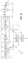
- FIG. 1a shows a system 100 as known prior to the present invention.
- the emission path 10 comprises the laser emission source 11, the modulator 12, the optical amplifier 13, the optical circulator 14 and the emission optics 15.
- the laser emission source 11 may be of a continuous emission type, with an emission wavelength of approximately 1550 nm (nanometer) and a power of 600 ⁇ J (microjoule), for example. It thus produces an initial laser radiation R 0 which is monochromatic or quasi-monochromatic. This initial laser radiation R 0 is transmitted to the modulator 12.
- the modulator 12 may be of the acousto-optic modulator type.
- the modulator 12 can be controlled to shift the optical frequency of the radiation by applying a frequency shift ⁇ 0 to it, which can be equal to 100 MHz (megahertz) for example.
- the pulses I which are thus produced by the modulator 12 are amplified by the optical amplifier 13, then transmitted to the emission optics 15 via the optical circulator 14.
- the emission optics 15 may have a telescope structure, for example.
- the amplified pulses I are thus transmitted towards a target T, which is external to the LIDAR system 100 and located at a distance D from the latter, measured according to the emission direction of the system 100.
- the distance D is less than the range L of the system 100, the latter being able to be equal to approximately 15 km (kilometer) as an example.
- All the pulses I which are thus emitted by the system 100 of [ Fig. 1a ] are identical and monochromatic or quasi-monochromatic.
- the secondary output 16 is located in the emission path 10 between the laser emission source 11 and the modulator 12 for shifting and chopping the pulses I.
- the detection path 20 shares the emission optics 15 and the optical circulator 14 with the emission path 10, and further comprises the heterodyne detector 21.
- the optics 15 has a function of collecting RI portions of the pulses I that have been retroreflected or backscattered by the target T.
- the heterodyne detector 21 is optically coupled to receive the retroreflected or backscattered RI pulse portions that have been collected by the optics 15, via the optical circulator 14, and to simultaneously receive a reference optical signal RR that is taken from the emission path 10 by the secondary output 16 of this emission path.
- this secondary output 16 is optically coupled to the heterodyne detector 21 in addition to the output of the optical circulator 14 which is dedicated to the detection channel 20.
- the heterodyne detector 21 can be a photodiode, in particular of the ultrafast photodiode type, on which the reference optical signal RR which comes from the secondary output 16 and the pulse parts RI which come from the target T are focused.
- the system 100 is preferably made using optical fiber technology.
- the optical amplifier 13 may be of the type designated by EDFA, for "Erbium-Doped Fiber Amplifier" in English, or erbium-doped fiber amplifier.
- the initial laser radiation R 0 is transmitted by a first segment S1 of optical fiber from the laser emission source 11 to the modulator 12, then from the latter to the amplifier 13 by a second segment S2 of optical fiber.
- the retroreflected or backscattered pulse parts RI which are collected by the optics 15 are injected into a third segment S3 of optical fiber at the output of the optical circulator 14 to bring them to the heterodyne detector 21.
- the secondary output 16 of the emission path 10 is produced by a fiber coupler, and connected to the heterodyne detector 21 by a fourth segment S4 of optical fiber.
- the heterodyne detection signal has a sinusoidal variation at the frequency ⁇ m .
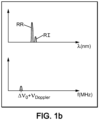
- the upper diagram of [ Fig. 1b ] shows the spectral composition of the radiation that is received by the heterodyne detector 21.
- the horizontal axis of this upper diagram of [ Fig. 1b ] identifies the wavelength values in the optical domain, denoted ⁇ and expressed in nanometers (nm).
- the vertical axis in arbitrary units, identifies the spectral intensity values.
- the radiation which is received by the heterodyne detector 21 comprises a first contribution which is constituted by the reference optical signal RR brought from the secondary output 16, and a second contribution which corresponds to the parts RI of the pulses which have been retroreflected by the target T.
- the reference optical signal RR is a part of the initial laser radiation R 0 , so that the corresponding contribution in the upper diagram of [ Fig. 1b ] is a very narrow peak, noted RR.
- the second contribution also has a narrow peak shape, denoted RI.
- the heterodyne detection signal shows the spectral composition of the heterodyne detection signal which corresponds to the spectral composition of the radiation received by the detector 21 as shown in the upper diagram.
- the horizontal axis of the lower diagram of [ Fig. 1b ] identifies the frequency values in the RF domain, denoted f and expressed in megahertz (MHz).
- the vertical axis is again in arbitrary units to identify the spectral intensity values of the heterodyne detection signal.
- the pulses I are backscattered by a multiplicity of targets which are distributed on the path of the pulse beam outside the system 100, from the emission optics 15.
- targets which are constituted by particles or aerosols present in suspension in the air, are entrained according to the local speed of movement of the air which exists at each location of the path of the beam.
- the person skilled in the art commonly designates such a distribution of targets by “continuous target”, “distributed target” or “volume target”.
- the RI pulse parts that are collected by the optics 15 and then transmitted to the detector 21 are spread out in time, corresponding to different separation distances depending on the emission direction of the system 100, where partial backscattering of the I pulses occurs.
- the heterodyne detection signal then has more complex temporal variations.
- the spectral analysis carried out by the module 30 is assumed to be known: it provides as a result a series of speed values V T which are assigned one-by-one to different values of the separation distance D.
- the separation distance resolution D is determined by the individual duration of the emitted pulses I, being equal to this individual duration divided by twice the propagation speed of the pulses outside the LIDAR system 100.
- the peak which corresponds to the RI pulse parts in the spectral composition of the radiation received by the detector 21 is broadened.
- the peak of the spectral composition of the heterodyne detection signal, in the RF domain, is broadened in a correlated manner.
- each pulse I as emitted by the LIDAR 100 system consists of several pulse spectral components which are simultaneous, and therefore are superimposed to form the pulse.
- Each component pulse spectral component is monochromatic or quasi-monochromatic, and each pulse I may consist of ten such pulse spectral components, for example.
- the differences between the wavelength values of two pulse spectral components which are spectrally neighbors may be constant, but not necessarily.
- wavelength differences between neighboring spectral components are called wavelength increment, and denoted ⁇ 1 .
- the increment wavelength ⁇ 1 corresponds to a frequency increment ⁇ 1 which is equal to -C ⁇ 1 / ⁇ 0 2 .
- the latter can be equal to 200 MHz, for example, in the RF domain.
- each pulse I is spectrally constituted by a comb, and all the pulses I which are successively emitted by the LIDAR system 100 are identical, with this same individual constitution.
- Such pulses I which are successively emitted can have individual durations equal to 2 ⁇ s (microsecond), and be emitted every 100 ⁇ s.
- the pulse repetition frequency I is equal to 10 kHz, while the pulse frequency which is effective for measuring target speeds, i.e. the PRF frequency, is equal to the product of this pulse repetition frequency by the number of pulse spectral components in each of the pulses I, i.e. 100 kHz.
- the modulator 12 then applies the frequency shift ⁇ 0 to each of the spectral components of the radiation R 1 . It further applies the division into pulses that are temporally separated to all the spectral components so that each pulse I that is emitted by the emission path 10 to the outside is composed of several spectral components that are all superimposed during the duration of the pulse.
- the radiation R 1 that is produced at the output by the modulator 17, as well as each pulse I that is emitted by the system 100 is now composed of a comb of spectral components.
- the frequency increment ⁇ 1 is greater than the sum of the spectral width of the components of the electrical modulation signal and that of the laser source 11, so that the comb spectral components are spectrally disjoint.
- the n sinusoidal components of the electrical modulation signal can be produced by a combination of n analog electrical oscillators.
- Such an alternative mode of generating the electrical modulation signal can indeed be simpler to implement.
- each pulse spectral component When retroreflected, each pulse spectral component is spectrally shifted due to the Doppler effect. Since the frequency increment ⁇ 1 is much lower than the optical frequency that corresponds to the wavelength ⁇ 0 , all pulse spectral components undergo the same Doppler effect frequency shift ⁇ Doppler . Furthermore, the frequency increment ⁇ 1 is chosen to be greater than all possible expected values for the Doppler effect frequency shift ⁇ Doppler added to the frequency shift ⁇ 0 .
- the secondary output 16 of the transmission channel 10 is located between the modulators 17 and 12 for the embodiment of [ Fig. 3a ].
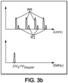
- the reference optical signal RR which is brought to the heterodyne detector 21 is a part of the radiation R 1 . It is therefore also constituted by a comb of frequency increment ⁇ 1 .
- the spectral composition of the radiation that is received by the heterodyne detector 21 then comprises the frequency increment comb ⁇ 1 , designated by RR, and an additional comb, which is designated by RI and which corresponds to the pulse parts that have been retroreflected or retroscattered and then collected by the optics 15.
- This additional comb contains the measurement information. It is shifted relative to the comb RR by A ⁇ 0 + ⁇ Doppler , in terms of optical frequency, also having ⁇ 1 as a frequency increment.
- each spectral component of the RR comb forms an interference with each of the spectral components of the RI comb, but appropriate filtering eliminates all interference between a component of the RR comb and a component of the RI comb which are not spectrally neighbors, i.e. which are distant from each other by more than 0.3 ⁇ 1 , for example. Possibly, such filtering is carried out by the detector 21 itself, due to its characteristic response time. Thus, only contributions remain in the heterodyne detection signal which correspond to the interferences between each component of the RR comb and that of the RI comb which is shifted relative to it by ⁇ 0 + ⁇ Doppler .
- the heterodyne detection signal has a signal-to-noise ratio value calculated on the spectrum which is increased compared to the system 100 of [ Fig. 1a ].
- the spectral analysis module 30 may be identical to that of the system 100 of [ Fig. 1a ].
- the spectrum of the radiation that is received by the heterodyne detector 21 comprises the RR peak that corresponds to the emission of the laser emission source 11, and the comb that is formed by the retroreflected or backscattered RI pulse parts that have been collected.
- This second comb is still designated by Rl.
- Each spectral component of the RI comb still corresponds to the spectral components of pulses, affected by the Doppler frequency shift ⁇ . These spectral components are still incoherent in the retroreflected or backscattered RI pulse parts that have been collected.
- the heterodyne detection signal is composed of the interferences of the spectral component of the RR peak with each of the spectral components of the RI comb.
- the heterodyne detection signal is then composed of several spectral components, whose RF center frequency values are ⁇ 0 + ⁇ Doppler +i ⁇ 1 , where i is an integer index that identifies the spectral components of the heterodyne detection signal.
- This spectral composition of the heterodyne detection signal is shown by the lower diagram of [ Fig. 4b ].
- the spectral analysis module 30 determines the value of the Doppler effect frequency shift ⁇ Doppler from the RF frequency values that are measured for the central values ⁇ 0 + ⁇ Doppler +i ⁇ 1 . For example, an elementary value is determined for ⁇ Doppler from each of the central values ⁇ 0 + ⁇ Doppler +i ⁇ 1 , and the final value of ⁇ Doppler is calculated by averaging the elementary values. Possibly, RF frequency values that correspond to the maximum intensity values of the RI peaks in the spectrum of the heterodyne detection signal can be used instead of the center frequency values of the same peaks, in order to determine the elementary ⁇ Doppler values which are deduced from the individual positions of the RI peaks.
- each pulse spectral component may have an individual peak power value that is just below a stimulated Brillouin scattering threshold that occurs in the optical fiber segments S1 and S2 as well as in the optical amplifier 13, the optical circulator 14 and the optical fiber segments between them and up to the emission optics 15.
- the power of each pulse I that is emitted by the system 100 to the outside to perform a velocity measurement is multiplied by the number n comp of the spectral components implemented in each pulse, relative to the system of [ Fig. 1a ].
- An improvement of a factor n comp 1/2 is thus obtained for the operation of the heterodyne detection LIDAR system.
- the pulsed heterodyne detection LIDAR systems according to the invention are therefore particularly suitable for measurement conditions where the retroreflected or backscattered pulse parts have low or very low powers. They are therefore particularly suitable for carrying out anemometric measurements.
- Fig. 5 shows a series of pulses I which are successively emitted by the LIDAR system, for which each pulse I consists of two disjoint spectral components separated by the wavelength difference 2 ⁇ 1 .
- This inter-component spectral difference 2 ⁇ 1 varies between two pulses I which are successive, according to the claimed invention periodically during the complete series of pulses I.
- the use of such a series of pulses of variable spectral compositions is compatible with the two embodiments of LIDAR systems according to the invention of [ Fig.
- [ Fig. 5 ] shows only two spectral components per pulse, the number of spectral components per pulse may be greater.
- the control of the electro-optical modulator 17 may be designed so that the radiation R 1 as it comes directly from the modulator 17 before being transmitted to the acousto-optical modulator 12, is devoid of a spectral component of significant amplitude at the wavelength value ⁇ 0 of the laser emission source 11.
Landscapes
- Engineering & Computer Science (AREA)
- Physics & Mathematics (AREA)
- Computer Networks & Wireless Communication (AREA)
- General Physics & Mathematics (AREA)
- Radar, Positioning & Navigation (AREA)
- Remote Sensing (AREA)
- Electromagnetism (AREA)
- Optical Radar Systems And Details Thereof (AREA)
Claims (13)
- Gepulstes LIDAR-System (100), das dazu eingerichtet ist, einen Wert einer Dopplereffekt-Frequenzverschiebung (ν Doppler), der eine Reihe von nacheinander vom System in Richtung eines Ziels (T) emittierten Strahlungsimpulsen (I) unterworfen ist, zwischen Teilen der Impulse, wie nach Rückreflexion oder Rückstreuung am Ziel empfangenen Impulsen, und den Impulsen, wie durch das System emittierten Impulsen, zu bestimmen und um aus dem für die Frequenzverschiebung bestimmten Wert eine Schätzung einer Geschwindigkeitskomponente (VT) des Ziels, die parallel zu einer optischen Emissionsrichtung des Systems ist, bereitzustellen, wobei das System (100) umfasst:- einen Emissionspfad (10), der zum Erzeugen der Impulsreihe (I) eingerichtet ist,- einen Detektionspfad (20), der zum Detektieren der Teile der nach Rückreflexion oder Rückstreuung am Ziel (T) empfangenen Impulse (RI) und Erzeugen der Heterodyndetektionssignale, die den Impulsen (I) der Reihe entsprechen, eingerichtet ist,- ein Spektralanalysemodul (30), das dazu eingerichtet ist, eine Spektralanalyse der Heterodyndetektionssignale durchzuführen, so dass der Wert der Frequenzverschiebung (ν Doppler) aus Heterodyndetektionsbeiträgen, die den Impulsen (I) der Serie entsprechen, resultiert, undwobei der Emissionspfad (10) ferner dazu eingerichtet ist, jeden der Impulse (I) als Überlagerung mehrerer Impulsspektralkomponenten zu bilden, die gleichzeitig, spektral disjunkt und eins zu eins verschiedenen Zentralwerten der Wellenlänge zugeordnet emittiert werden, undwobei das System (100) so eingerichtet ist, dass der Wert der Frequenzverschiebung (ν Doppler), der durch das Spektralanalysemodul (30) bestimmt wird, aus mehreren Heterodyndetektionsbeiträgen resultiert, die jeweils den spektralen Komponenten der Impulse (I) der Reihe entsprechen,wobei das System (100) dadurch gekennzeichnet ist, dass es ferner so eingerichtet ist, dass die disjunkten Spektralkomponenten von zwei Impulsen (I), die nacheinander emittiert werden, durch einen spektralen Abstand zwischen den Komponenten getrennt sind, der zwischen den beiden aufeinanderfolgenden Impulsen variiert, und dass der spektrale Abstand zwischen den Komponenten im Verlauf der kompletten Impulsreihe periodisch variiert.
- Gepulstes LIDAR-System (100) nach Anspruch 1, das dazu eingerichtet ist, eine Schätzung einer Luftgeschwindigkeitskomponente bereitzustellen, wenn das System darauf ausgerichtet ist, die Strahlungsimpulse (I) in Richtung eines Abschnitts der Atmosphäre zu emittieren, der suspendierte Teilchen enthält, die das Ziel bilden (T), wobei die Teilchen diese Strahlung rückstreuend wirken.
- Gepulstes LIDAR-System (100) nach Anspruch 1 oder 2, wobei der Emissionspfad (10) ferner so eingerichtet ist, dass die Spektralkomponenten jedes Impulses (I) spektral um mindestens 10 MHz, vorzugsweise mindestens 20 MHz, und höchstens 2000 MHz. disjunkt sind.
- Gepulstes LIDAR-System (100) nach einem der vorstehenden Ansprüche, wobei der Emissionspfad (10) ferner so eingerichtet ist, dass spektrale Abstände (Δν 1), die zwischen zwei beliebigen spektral benachbarten Spektralimpulskomponenten bestehen, zwischen verschiedenen Paaren benachbarter Spektralimpulskomponenten konstant sind.
- Gepulstes LIDAR-System (100) nach einem der vorstehenden Ansprüche, wobei der Emissionspfad (10) ferner so eingerichtet ist, dass eine Anzahl der spektral disjunkten Impulsspektralkomponenten, die jeden Impuls (I) bilden, zwischen 2 und 20, vorzugsweise zwischen 4 und 12, liegt.
- Gepulstes LIDAR-System (100) nach einem der vorstehenden Ansprüche, wobei der Emissionspfad (10) umfasst:- eine Laseremissionsquelle (11), die eingerichtet ist, um eine initiale Laserstrahlung (R0) zu erzeugen;- einen Kammerzeugungsmodulator (17), der dazu angeordnet ist, die initiale Laserstrahlung (R0) gemäß einem Modulationssignal, das an einen Steuereingang des Kammerzeugungsmodulators angelegt wird, zu ändern, und- einen Modulationssignalerzeuger (18), der so angeschlossen ist, dass er das Modulationssignal an den Steuereingang des Kammerzeugungsmodulators (17) anlegt, wobei das Modulationssignal so beschaffen ist, dass die initiale Laserstrahlung (R0) vom Kammerzeugungsmodulator (17) in einen Satz spektraler Komponenten umgewandelt wird, die dazu bestimmt sind, nacheinander die spektralen Komponenten von Impulsen zu bilden.
- Gepulstes LIDAR-System (100) nach Anspruch 6, wobei der Kammerzeugungsmodulator (17) ein elektrooptischer Kammerzeugungsmodulator ist und die Reihe von Impulsen (I) mit dem spektralen Abstand zwischen den Komponenten, der zwischen zwei nacheinander emittierten Impulsen variiert, durch Steuerung des elektrooptischen Kammerzeugungsmodulators erhalten wird.
- Gepulstes LIDAR-System (100) nach Anspruch 7, wobei die Steuerung des elektrooptischen Kammerzeugungsmodulators (17) so eingerichtet ist, dass die Strahlung (R1), so wie sie direkt vom Modulator kommt, bevor sie an einen akustooptischen Frequenzverschiebungs- und Impulsschneidemodulator (12) übertragen wird, keine spektrale Komponente bei einem Emissionswellenlängenwert der Laseremissionsquelle (11) aufweist.
- Gepulstes LIDAR-System (100) nach einem der Ansprüche 1 bis 8, wobei ein Referenzeingang des Detektionspfads (20) mit einem sekundären Ausgang (16) des Emissionspfads (10) verbunden ist, um ein optisches Referenzsignal (RR) zu empfangen, das Referenzspektralkomponenten umfasst, die eins zu eins den Spektralkomponenten der Impulse (I) entsprechen, mit einer spektralen Verschiebung (Δν 0) zwischen jeder Impulsspektralkomponente und der Referenzspektralkomponente, die dieser Impulsspektralkomponente entspricht, die für alle Impulsspektralkomponenten identisch ist,
so dass die Heterodyndetektionsbeiträge, die den Impulsspektralkomponenten im Heterodyndetektionssignal, wie sie vom Detektionspfad (20) erzeugt werden, zugeordnet sind, alle spektral überlagert sind. - Gepulstes LIDAR-System (100) nach Anspruch 9 und einem der Ansprüche 6 bis 8, wobei der sekundäre Ausgang (16) des Emissionspfads (10) in dem Emissionspfad bezüglich einer Ausbreitungsrichtung der Strahlung im Emissionspfad stromabwärts des Kammerzeugungsmodulators (17) angeordnet ist.
- Gepulstes LIDAR-System (100) nach einem der Ansprüche 1 bis 8, wobei ein Referenzeingang des Detektionspfads (20) mit einem sekundären Ausgang (16) des Emissionspfads (10) verbunden ist, um ein optisches Referenzsignal zu empfangen (RR), das monochromatisch ist, so dass die Heterodyndetektionsbeiträge, die den Impulsspektralkomponenten im Heterodyndetektionssignal, wie es durch den Detektionspfad (20) erzeugt wird, zugeordnet sind, entsprechend einer Verteilung der spektralen Impulskomponenten spektral zueinander verschoben sind, und wobei das Spektralanalysemodul (30) dazu eingerichtet ist, den Wert der Dopplereffekt-Frequenzverschiebung(ν Doppler) aus zentralen Frequenzwerten abzuleiten, die jeweils relativ zu jedem der Heterodyndetektionsbeiträge sind.
- Gepulstes LIDAR-System (100) nach Anspruch 11 und einem der Ansprüche 6 bis 8, wobei der sekundäre Ausgang (16) des Emissionspfads (10) in dem Emissionspfad bezüglich einer Ausbreitungsrichtung der Strahlung im Emissionspfad stromaufwärts des Kammerzeugungsmodulators (17) angeordnet ist.
- Gepulstes LIDAR-System (100) nach einem der vorstehenden Ansprüche, wobei der Emissionspfad (10) und/oder der Detektionspfad (20) durch Glasfasertechnologie umgesetzt ist, um Komponenten des Emissionspfads und/oder des Detektionspfads miteinander zu verbinden.
Applications Claiming Priority (2)
| Application Number | Priority Date | Filing Date | Title |
|---|---|---|---|
| FR2104768A FR3122738B1 (fr) | 2021-05-06 | 2021-05-06 | Systeme lidar a impulsions |
| PCT/FR2022/050781 WO2022234211A1 (fr) | 2021-05-06 | 2022-04-26 | Systeme lidar a impulsions |
Publications (2)
| Publication Number | Publication Date |
|---|---|
| EP4334749A1 EP4334749A1 (de) | 2024-03-13 |
| EP4334749B1 true EP4334749B1 (de) | 2024-11-27 |
Family
ID=77999020
Family Applications (1)
| Application Number | Title | Priority Date | Filing Date |
|---|---|---|---|
| EP22735526.0A Active EP4334749B1 (de) | 2021-05-06 | 2022-04-26 | Gepulstes lidar-system |
Country Status (7)
| Country | Link |
|---|---|
| US (1) | US20240264287A1 (de) |
| EP (1) | EP4334749B1 (de) |
| JP (1) | JP2024517454A (de) |
| CN (1) | CN117597602A (de) |
| ES (1) | ES3007338T3 (de) |
| FR (1) | FR3122738B1 (de) |
| WO (1) | WO2022234211A1 (de) |
Families Citing this family (2)
| Publication number | Priority date | Publication date | Assignee | Title |
|---|---|---|---|---|
| FR3122928B1 (fr) * | 2021-05-11 | 2023-05-19 | Office National Detudes Rech Aerospatiales | Systeme lidar a compression d’impulsion |
| CN117092662B (zh) * | 2023-10-17 | 2024-02-23 | 中国科学技术大学 | 一种风场探测的量子干涉激光雷达系统和方法 |
Family Cites Families (7)
| Publication number | Priority date | Publication date | Assignee | Title |
|---|---|---|---|---|
| EP2796890B1 (de) * | 2011-12-21 | 2017-06-28 | Mitsubishi Electric Corporation | Laserradargerät |
| US20160291137A1 (en) * | 2013-12-10 | 2016-10-06 | Mitsubishi Electric Corporation | Laser radar device |
| WO2018109888A1 (ja) * | 2016-12-15 | 2018-06-21 | 三菱電機株式会社 | 風計測ライダ装置 |
| US10901089B2 (en) * | 2018-03-26 | 2021-01-26 | Huawei Technologies Co., Ltd. | Coherent LIDAR method and apparatus |
| AU2018451571A1 (en) * | 2018-12-03 | 2020-12-10 | Nanjing Movelaser Technology Co., Ltd. | Wind field information measurement method and nacelle-based lidar |
| CN111751844B (zh) * | 2020-07-07 | 2024-02-23 | 南京泰爱信科技有限公司 | 一种基于频域编码技术的相干激光雷达 |
| CN112698355A (zh) * | 2020-12-03 | 2021-04-23 | 董晶晶 | 一种基于电光调制技术的多波长相干激光雷达 |
-
2021
- 2021-05-06 FR FR2104768A patent/FR3122738B1/fr active Active
-
2022
- 2022-04-26 US US18/558,967 patent/US20240264287A1/en active Pending
- 2022-04-26 JP JP2023568307A patent/JP2024517454A/ja active Pending
- 2022-04-26 WO PCT/FR2022/050781 patent/WO2022234211A1/fr not_active Ceased
- 2022-04-26 EP EP22735526.0A patent/EP4334749B1/de active Active
- 2022-04-26 CN CN202280047405.3A patent/CN117597602A/zh active Pending
- 2022-04-26 ES ES22735526T patent/ES3007338T3/es active Active
Also Published As
| Publication number | Publication date |
|---|---|
| FR3122738A1 (fr) | 2022-11-11 |
| US20240264287A1 (en) | 2024-08-08 |
| JP2024517454A (ja) | 2024-04-22 |
| FR3122738B1 (fr) | 2023-04-28 |
| EP4334749A1 (de) | 2024-03-13 |
| WO2022234211A1 (fr) | 2022-11-10 |
| ES3007338T3 (en) | 2025-03-19 |
| CN117597602A (zh) | 2024-02-23 |
Similar Documents
| Publication | Publication Date | Title |
|---|---|---|
| EP3371554B1 (de) | Optoelektronische vorrichtung zur verteilten messung mittels brillouin-streuung | |
| EP2325655B1 (de) | Geschwindigkeits- oder Vibrationserfassung mittels Heterodyn-LIDAR | |
| EP3635354B1 (de) | Optoelektronische vorrichtung zur verteilten messung mittels optischer faser | |
| EP2135111B1 (de) | Mehrfarben-telemetrie | |
| EP4334743A1 (de) | Gepulstes lidar-system | |
| FR3022349A1 (fr) | Lidar doppler a mesure relative de vitesse | |
| EP4337980B1 (de) | Pulskompressions-lidarsystem | |
| EP3353502B1 (de) | Messsystem und temperatur und/oder formänderungssensor mit brillouinrückreflexionsanalyse | |
| WO2022234211A1 (fr) | Systeme lidar a impulsions | |
| EP3995857B1 (de) | Lidar-system für differentielle absorptions- und hintergrundabstandsmessungen | |
| FR2811080A1 (fr) | Dispositif de mesure de distorsion de fibre optique | |
| EP3584604B1 (de) | Lichtradar zur heterodynen detektion über einen lokalen oszillator und doppelten prüfstrahl mit einer oder mehreren simultanen frequenzen, und lichtradar-detektionsverfahren durch detektion mit doppelter heterodyner frequenzumwandlung | |
| FR3015668A1 (fr) | Dispositif de caracterisation d'un phenomene physique par ablation de fibre optique a reseaux de bragg | |
| EP4031909B1 (de) | Lidarsystem für anemometrische messungen | |
| JP7424250B2 (ja) | 光ファイバ歪測定装置及び光ファイバ歪測定方法 | |
| CA3163393A1 (fr) | Calibration d'un systeme lidar | |
| WO2025012096A1 (fr) | Systeme lidar a detection directe | |
| FR3139391A1 (fr) | Systeme lidar pour mesures velocimetriques | |
| FR3098603A1 (fr) | Dispositif pour réaliser une série de mesures optiques sur des points voisins par multiplexage en longueur d’onde. | |
| FR3160286A1 (fr) | Appareil et procédé de réflectométrie par mesure de signal de bruit interférométrique optique |
Legal Events
| Date | Code | Title | Description |
|---|---|---|---|
| STAA | Information on the status of an ep patent application or granted ep patent |
Free format text: STATUS: UNKNOWN |
|
| STAA | Information on the status of an ep patent application or granted ep patent |
Free format text: STATUS: THE INTERNATIONAL PUBLICATION HAS BEEN MADE |
|
| PUAI | Public reference made under article 153(3) epc to a published international application that has entered the european phase |
Free format text: ORIGINAL CODE: 0009012 |
|
| STAA | Information on the status of an ep patent application or granted ep patent |
Free format text: STATUS: REQUEST FOR EXAMINATION WAS MADE |
|
| 17P | Request for examination filed |
Effective date: 20231103 |
|
| AK | Designated contracting states |
Kind code of ref document: A1 Designated state(s): AL AT BE BG CH CY CZ DE DK EE ES FI FR GB GR HR HU IE IS IT LI LT LU LV MC MK MT NL NO PL PT RO RS SE SI SK SM TR |
|
| DAV | Request for validation of the european patent (deleted) | ||
| DAX | Request for extension of the european patent (deleted) | ||
| GRAP | Despatch of communication of intention to grant a patent |
Free format text: ORIGINAL CODE: EPIDOSNIGR1 |
|
| STAA | Information on the status of an ep patent application or granted ep patent |
Free format text: STATUS: GRANT OF PATENT IS INTENDED |
|
| INTG | Intention to grant announced |
Effective date: 20240916 |
|
| GRAS | Grant fee paid |
Free format text: ORIGINAL CODE: EPIDOSNIGR3 |
|
| GRAA | (expected) grant |
Free format text: ORIGINAL CODE: 0009210 |
|
| STAA | Information on the status of an ep patent application or granted ep patent |
Free format text: STATUS: THE PATENT HAS BEEN GRANTED |
|
| AK | Designated contracting states |
Kind code of ref document: B1 Designated state(s): AL AT BE BG CH CY CZ DE DK EE ES FI FR GB GR HR HU IE IS IT LI LT LU LV MC MK MT NL NO PL PT RO RS SE SI SK SM TR |
|
| REG | Reference to a national code |
Ref country code: GB Ref legal event code: FG4D Free format text: NOT ENGLISH |
|
| REG | Reference to a national code |
Ref country code: CH Ref legal event code: EP |
|
| REG | Reference to a national code |
Ref country code: IE Ref legal event code: FG4D Free format text: LANGUAGE OF EP DOCUMENT: FRENCH |
|
| REG | Reference to a national code |
Ref country code: DE Ref legal event code: R096 Ref document number: 602022008238 Country of ref document: DE |
|
| REG | Reference to a national code |
Ref country code: ES Ref legal event code: FG2A Ref document number: 3007338 Country of ref document: ES Kind code of ref document: T3 Effective date: 20250319 |
|
| REG | Reference to a national code |
Ref country code: LT Ref legal event code: MG9D |
|
| REG | Reference to a national code |
Ref country code: NL Ref legal event code: MP Effective date: 20241127 |
|
| PG25 | Lapsed in a contracting state [announced via postgrant information from national office to epo] |
Ref country code: IS Free format text: LAPSE BECAUSE OF FAILURE TO SUBMIT A TRANSLATION OF THE DESCRIPTION OR TO PAY THE FEE WITHIN THE PRESCRIBED TIME-LIMIT Effective date: 20250327 Ref country code: HR Free format text: LAPSE BECAUSE OF FAILURE TO SUBMIT A TRANSLATION OF THE DESCRIPTION OR TO PAY THE FEE WITHIN THE PRESCRIBED TIME-LIMIT Effective date: 20241127 Ref country code: PT Free format text: LAPSE BECAUSE OF FAILURE TO SUBMIT A TRANSLATION OF THE DESCRIPTION OR TO PAY THE FEE WITHIN THE PRESCRIBED TIME-LIMIT Effective date: 20250327 |
|
| PG25 | Lapsed in a contracting state [announced via postgrant information from national office to epo] |
Ref country code: FI Free format text: LAPSE BECAUSE OF FAILURE TO SUBMIT A TRANSLATION OF THE DESCRIPTION OR TO PAY THE FEE WITHIN THE PRESCRIBED TIME-LIMIT Effective date: 20241127 Ref country code: NL Free format text: LAPSE BECAUSE OF FAILURE TO SUBMIT A TRANSLATION OF THE DESCRIPTION OR TO PAY THE FEE WITHIN THE PRESCRIBED TIME-LIMIT Effective date: 20241127 |
|
| REG | Reference to a national code |
Ref country code: AT Ref legal event code: MK05 Ref document number: 1746197 Country of ref document: AT Kind code of ref document: T Effective date: 20241127 |
|
| PG25 | Lapsed in a contracting state [announced via postgrant information from national office to epo] |
Ref country code: BG Free format text: LAPSE BECAUSE OF FAILURE TO SUBMIT A TRANSLATION OF THE DESCRIPTION OR TO PAY THE FEE WITHIN THE PRESCRIBED TIME-LIMIT Effective date: 20241127 |
|
| PG25 | Lapsed in a contracting state [announced via postgrant information from national office to epo] |
Ref country code: NO Free format text: LAPSE BECAUSE OF FAILURE TO SUBMIT A TRANSLATION OF THE DESCRIPTION OR TO PAY THE FEE WITHIN THE PRESCRIBED TIME-LIMIT Effective date: 20250227 |
|
| PG25 | Lapsed in a contracting state [announced via postgrant information from national office to epo] |
Ref country code: AT Free format text: LAPSE BECAUSE OF FAILURE TO SUBMIT A TRANSLATION OF THE DESCRIPTION OR TO PAY THE FEE WITHIN THE PRESCRIBED TIME-LIMIT Effective date: 20241127 Ref country code: GR Free format text: LAPSE BECAUSE OF FAILURE TO SUBMIT A TRANSLATION OF THE DESCRIPTION OR TO PAY THE FEE WITHIN THE PRESCRIBED TIME-LIMIT Effective date: 20250228 Ref country code: LV Free format text: LAPSE BECAUSE OF FAILURE TO SUBMIT A TRANSLATION OF THE DESCRIPTION OR TO PAY THE FEE WITHIN THE PRESCRIBED TIME-LIMIT Effective date: 20241127 |
|
| PG25 | Lapsed in a contracting state [announced via postgrant information from national office to epo] |
Ref country code: PL Free format text: LAPSE BECAUSE OF FAILURE TO SUBMIT A TRANSLATION OF THE DESCRIPTION OR TO PAY THE FEE WITHIN THE PRESCRIBED TIME-LIMIT Effective date: 20241127 |
|
| PG25 | Lapsed in a contracting state [announced via postgrant information from national office to epo] |
Ref country code: RS Free format text: LAPSE BECAUSE OF FAILURE TO SUBMIT A TRANSLATION OF THE DESCRIPTION OR TO PAY THE FEE WITHIN THE PRESCRIBED TIME-LIMIT Effective date: 20250227 |
|
| PG25 | Lapsed in a contracting state [announced via postgrant information from national office to epo] |
Ref country code: SM Free format text: LAPSE BECAUSE OF FAILURE TO SUBMIT A TRANSLATION OF THE DESCRIPTION OR TO PAY THE FEE WITHIN THE PRESCRIBED TIME-LIMIT Effective date: 20241127 |
|
| PGFP | Annual fee paid to national office [announced via postgrant information from national office to epo] |
Ref country code: DE Payment date: 20250528 Year of fee payment: 4 |
|
| PG25 | Lapsed in a contracting state [announced via postgrant information from national office to epo] |
Ref country code: DK Free format text: LAPSE BECAUSE OF FAILURE TO SUBMIT A TRANSLATION OF THE DESCRIPTION OR TO PAY THE FEE WITHIN THE PRESCRIBED TIME-LIMIT Effective date: 20241127 |
|
| PGFP | Annual fee paid to national office [announced via postgrant information from national office to epo] |
Ref country code: ES Payment date: 20250626 Year of fee payment: 4 |
|
| PG25 | Lapsed in a contracting state [announced via postgrant information from national office to epo] |
Ref country code: EE Free format text: LAPSE BECAUSE OF FAILURE TO SUBMIT A TRANSLATION OF THE DESCRIPTION OR TO PAY THE FEE WITHIN THE PRESCRIBED TIME-LIMIT Effective date: 20241127 |
|
| PGFP | Annual fee paid to national office [announced via postgrant information from national office to epo] |
Ref country code: FR Payment date: 20250429 Year of fee payment: 4 |
|
| PGFP | Annual fee paid to national office [announced via postgrant information from national office to epo] |
Ref country code: CH Payment date: 20250602 Year of fee payment: 4 |
|
| PG25 | Lapsed in a contracting state [announced via postgrant information from national office to epo] |
Ref country code: RO Free format text: LAPSE BECAUSE OF FAILURE TO SUBMIT A TRANSLATION OF THE DESCRIPTION OR TO PAY THE FEE WITHIN THE PRESCRIBED TIME-LIMIT Effective date: 20241127 |
|
| PG25 | Lapsed in a contracting state [announced via postgrant information from national office to epo] |
Ref country code: SK Free format text: LAPSE BECAUSE OF FAILURE TO SUBMIT A TRANSLATION OF THE DESCRIPTION OR TO PAY THE FEE WITHIN THE PRESCRIBED TIME-LIMIT Effective date: 20241127 |
|
| PG25 | Lapsed in a contracting state [announced via postgrant information from national office to epo] |
Ref country code: CZ Free format text: LAPSE BECAUSE OF FAILURE TO SUBMIT A TRANSLATION OF THE DESCRIPTION OR TO PAY THE FEE WITHIN THE PRESCRIBED TIME-LIMIT Effective date: 20241127 |
|
| PG25 | Lapsed in a contracting state [announced via postgrant information from national office to epo] |
Ref country code: IT Free format text: LAPSE BECAUSE OF FAILURE TO SUBMIT A TRANSLATION OF THE DESCRIPTION OR TO PAY THE FEE WITHIN THE PRESCRIBED TIME-LIMIT Effective date: 20241127 |
|
| REG | Reference to a national code |
Ref country code: DE Ref legal event code: R097 Ref document number: 602022008238 Country of ref document: DE |
|
| PG25 | Lapsed in a contracting state [announced via postgrant information from national office to epo] |
Ref country code: SE Free format text: LAPSE BECAUSE OF FAILURE TO SUBMIT A TRANSLATION OF THE DESCRIPTION OR TO PAY THE FEE WITHIN THE PRESCRIBED TIME-LIMIT Effective date: 20241127 |
|
| PLBE | No opposition filed within time limit |
Free format text: ORIGINAL CODE: 0009261 |
|
| STAA | Information on the status of an ep patent application or granted ep patent |
Free format text: STATUS: NO OPPOSITION FILED WITHIN TIME LIMIT |
|
| 26N | No opposition filed |
Effective date: 20250828 |
|
| PG25 | Lapsed in a contracting state [announced via postgrant information from national office to epo] |
Ref country code: LU Free format text: LAPSE BECAUSE OF NON-PAYMENT OF DUE FEES Effective date: 20250426 |
|
| PG25 | Lapsed in a contracting state [announced via postgrant information from national office to epo] |
Ref country code: MC Free format text: LAPSE BECAUSE OF FAILURE TO SUBMIT A TRANSLATION OF THE DESCRIPTION OR TO PAY THE FEE WITHIN THE PRESCRIBED TIME-LIMIT Effective date: 20241127 |
|
| REG | Reference to a national code |
Ref country code: BE Ref legal event code: MM Effective date: 20250430 |
|
| PG25 | Lapsed in a contracting state [announced via postgrant information from national office to epo] |
Ref country code: BE Free format text: LAPSE BECAUSE OF NON-PAYMENT OF DUE FEES Effective date: 20250430 |
|
| PG25 | Lapsed in a contracting state [announced via postgrant information from national office to epo] |
Ref country code: IE Free format text: LAPSE BECAUSE OF NON-PAYMENT OF DUE FEES Effective date: 20250426 |