EP4146367B1 - Automatisierter durchlasstest für einen filterkorb - Google Patents
Automatisierter durchlasstest für einen filterkorb Download PDFInfo
- Publication number
- EP4146367B1 EP4146367B1 EP21724224.7A EP21724224A EP4146367B1 EP 4146367 B1 EP4146367 B1 EP 4146367B1 EP 21724224 A EP21724224 A EP 21724224A EP 4146367 B1 EP4146367 B1 EP 4146367B1
- Authority
- EP
- European Patent Office
- Prior art keywords
- liquid
- permeability
- unit
- volume
- cleaning
- Prior art date
- Legal status (The legal status is an assumption and is not a legal conclusion. Google has not performed a legal analysis and makes no representation as to the accuracy of the status listed.)
- Active
Links
Images


Classifications
-
- B—PERFORMING OPERATIONS; TRANSPORTING
- B01—PHYSICAL OR CHEMICAL PROCESSES OR APPARATUS IN GENERAL
- B01D—SEPARATION
- B01D29/00—Filters with filtering elements stationary during filtration, e.g. pressure or suction filters, not covered by groups B01D24/00 - B01D27/00; Filtering elements therefor
- B01D29/62—Regenerating the filter material in the filter
- B01D29/66—Regenerating the filter material in the filter by flushing, e.g. counter-current air-bumps
-
- G—PHYSICS
- G01—MEASURING; TESTING
- G01N—INVESTIGATING OR ANALYSING MATERIALS BY DETERMINING THEIR CHEMICAL OR PHYSICAL PROPERTIES
- G01N15/00—Investigating characteristics of particles; Investigating permeability, pore-volume or surface-area of porous materials
- G01N15/08—Investigating permeability, pore-volume, or surface area of porous materials
-
- B—PERFORMING OPERATIONS; TRANSPORTING
- B01—PHYSICAL OR CHEMICAL PROCESSES OR APPARATUS IN GENERAL
- B01D—SEPARATION
- B01D29/00—Filters with filtering elements stationary during filtration, e.g. pressure or suction filters, not covered by groups B01D24/00 - B01D27/00; Filtering elements therefor
- B01D29/11—Filters with filtering elements stationary during filtration, e.g. pressure or suction filters, not covered by groups B01D24/00 - B01D27/00; Filtering elements therefor with bag, cage, hose, tube, sleeve or like filtering elements
- B01D29/31—Self-supporting filtering elements
- B01D29/35—Self-supporting filtering elements arranged for outward flow filtration
-
- B—PERFORMING OPERATIONS; TRANSPORTING
- B01—PHYSICAL OR CHEMICAL PROCESSES OR APPARATUS IN GENERAL
- B01D—SEPARATION
- B01D29/00—Filters with filtering elements stationary during filtration, e.g. pressure or suction filters, not covered by groups B01D24/00 - B01D27/00; Filtering elements therefor
- B01D29/60—Filters with filtering elements stationary during filtration, e.g. pressure or suction filters, not covered by groups B01D24/00 - B01D27/00; Filtering elements therefor integrally combined with devices for controlling the filtration
-
- B—PERFORMING OPERATIONS; TRANSPORTING
- B01—PHYSICAL OR CHEMICAL PROCESSES OR APPARATUS IN GENERAL
- B01D—SEPARATION
- B01D29/00—Filters with filtering elements stationary during filtration, e.g. pressure or suction filters, not covered by groups B01D24/00 - B01D27/00; Filtering elements therefor
- B01D29/62—Regenerating the filter material in the filter
- B01D29/64—Regenerating the filter material in the filter by scrapers, brushes, nozzles, or the like, acting on the cake side of the filtering element
- B01D29/6438—Regenerating the filter material in the filter by scrapers, brushes, nozzles, or the like, acting on the cake side of the filtering element nozzles
-
- B—PERFORMING OPERATIONS; TRANSPORTING
- B08—CLEANING
- B08B—CLEANING IN GENERAL; PREVENTION OF FOULING IN GENERAL
- B08B13/00—Accessories or details of general applicability for machines or apparatus for cleaning
-
- B—PERFORMING OPERATIONS; TRANSPORTING
- B08—CLEANING
- B08B—CLEANING IN GENERAL; PREVENTION OF FOULING IN GENERAL
- B08B3/00—Cleaning by methods involving the use or presence of liquid or steam
- B08B3/02—Cleaning by the force of jets or sprays
-
- B—PERFORMING OPERATIONS; TRANSPORTING
- B08—CLEANING
- B08B—CLEANING IN GENERAL; PREVENTION OF FOULING IN GENERAL
- B08B3/00—Cleaning by methods involving the use or presence of liquid or steam
- B08B3/04—Cleaning involving contact with liquid
- B08B3/08—Cleaning involving contact with liquid the liquid having chemical or dissolving effect
-
- C—CHEMISTRY; METALLURGY
- C02—TREATMENT OF WATER, WASTE WATER, SEWAGE, OR SLUDGE
- C02F—TREATMENT OF WATER, WASTE WATER, SEWAGE, OR SLUDGE
- C02F1/00—Treatment of water, waste water, or sewage
- C02F1/001—Processes for the treatment of water whereby the filtration technique is of importance
-
- C—CHEMISTRY; METALLURGY
- C02—TREATMENT OF WATER, WASTE WATER, SEWAGE, OR SLUDGE
- C02F—TREATMENT OF WATER, WASTE WATER, SEWAGE, OR SLUDGE
- C02F3/00—Biological treatment of water, waste water, or sewage
- C02F3/006—Regulation methods for biological treatment
-
- C—CHEMISTRY; METALLURGY
- C02—TREATMENT OF WATER, WASTE WATER, SEWAGE, OR SLUDGE
- C02F—TREATMENT OF WATER, WASTE WATER, SEWAGE, OR SLUDGE
- C02F3/00—Biological treatment of water, waste water, or sewage
- C02F3/02—Aerobic processes
-
- G—PHYSICS
- G01—MEASURING; TESTING
- G01N—INVESTIGATING OR ANALYSING MATERIALS BY DETERMINING THEIR CHEMICAL OR PHYSICAL PROPERTIES
- G01N15/00—Investigating characteristics of particles; Investigating permeability, pore-volume or surface-area of porous materials
- G01N15/08—Investigating permeability, pore-volume, or surface area of porous materials
- G01N15/082—Investigating permeability by forcing a fluid through a sample
-
- B—PERFORMING OPERATIONS; TRANSPORTING
- B01—PHYSICAL OR CHEMICAL PROCESSES OR APPARATUS IN GENERAL
- B01D—SEPARATION
- B01D2201/00—Details relating to filtering apparatus
- B01D2201/08—Regeneration of the filter
- B01D2201/081—Regeneration of the filter using nozzles or suction devices
-
- B—PERFORMING OPERATIONS; TRANSPORTING
- B01—PHYSICAL OR CHEMICAL PROCESSES OR APPARATUS IN GENERAL
- B01D—SEPARATION
- B01D2201/00—Details relating to filtering apparatus
- B01D2201/08—Regeneration of the filter
- B01D2201/085—Regeneration of the filter using another chemical than the liquid to be filtered
-
- C—CHEMISTRY; METALLURGY
- C02—TREATMENT OF WATER, WASTE WATER, SEWAGE, OR SLUDGE
- C02F—TREATMENT OF WATER, WASTE WATER, SEWAGE, OR SLUDGE
- C02F2103/00—Nature of the water, waste water, sewage or sludge to be treated
- C02F2103/005—Black water originating from toilets
-
- C—CHEMISTRY; METALLURGY
- C02—TREATMENT OF WATER, WASTE WATER, SEWAGE, OR SLUDGE
- C02F—TREATMENT OF WATER, WASTE WATER, SEWAGE, OR SLUDGE
- C02F2201/00—Apparatus for treatment of water, waste water or sewage
- C02F2201/008—Mobile apparatus and plants, e.g. mounted on a vehicle
-
- C—CHEMISTRY; METALLURGY
- C02—TREATMENT OF WATER, WASTE WATER, SEWAGE, OR SLUDGE
- C02F—TREATMENT OF WATER, WASTE WATER, SEWAGE, OR SLUDGE
- C02F2209/00—Controlling or monitoring parameters in water treatment
- C02F2209/003—Downstream control, i.e. outlet monitoring, e.g. to check the treating agents, such as halogens or ozone, leaving the process
-
- C—CHEMISTRY; METALLURGY
- C02—TREATMENT OF WATER, WASTE WATER, SEWAGE, OR SLUDGE
- C02F—TREATMENT OF WATER, WASTE WATER, SEWAGE, OR SLUDGE
- C02F2209/00—Controlling or monitoring parameters in water treatment
- C02F2209/05—Conductivity or salinity
-
- C—CHEMISTRY; METALLURGY
- C02—TREATMENT OF WATER, WASTE WATER, SEWAGE, OR SLUDGE
- C02F—TREATMENT OF WATER, WASTE WATER, SEWAGE, OR SLUDGE
- C02F2209/00—Controlling or monitoring parameters in water treatment
- C02F2209/11—Turbidity
-
- C—CHEMISTRY; METALLURGY
- C02—TREATMENT OF WATER, WASTE WATER, SEWAGE, OR SLUDGE
- C02F—TREATMENT OF WATER, WASTE WATER, SEWAGE, OR SLUDGE
- C02F2209/00—Controlling or monitoring parameters in water treatment
- C02F2209/40—Liquid flow rate
-
- C—CHEMISTRY; METALLURGY
- C02—TREATMENT OF WATER, WASTE WATER, SEWAGE, OR SLUDGE
- C02F—TREATMENT OF WATER, WASTE WATER, SEWAGE, OR SLUDGE
- C02F2209/00—Controlling or monitoring parameters in water treatment
- C02F2209/42—Liquid level
-
- C—CHEMISTRY; METALLURGY
- C02—TREATMENT OF WATER, WASTE WATER, SEWAGE, OR SLUDGE
- C02F—TREATMENT OF WATER, WASTE WATER, SEWAGE, OR SLUDGE
- C02F2209/00—Controlling or monitoring parameters in water treatment
- C02F2209/44—Time
- C02F2209/445—Filter life
-
- C—CHEMISTRY; METALLURGY
- C02—TREATMENT OF WATER, WASTE WATER, SEWAGE, OR SLUDGE
- C02F—TREATMENT OF WATER, WASTE WATER, SEWAGE, OR SLUDGE
- C02F2303/00—Specific treatment goals
- C02F2303/16—Regeneration of sorbents, filters
-
- C—CHEMISTRY; METALLURGY
- C02—TREATMENT OF WATER, WASTE WATER, SEWAGE, OR SLUDGE
- C02F—TREATMENT OF WATER, WASTE WATER, SEWAGE, OR SLUDGE
- C02F2303/00—Specific treatment goals
- C02F2303/24—Separation of coarse particles, e.g. by using sieves or screens
-
- G—PHYSICS
- G01—MEASURING; TESTING
- G01N—INVESTIGATING OR ANALYSING MATERIALS BY DETERMINING THEIR CHEMICAL OR PHYSICAL PROPERTIES
- G01N15/00—Investigating characteristics of particles; Investigating permeability, pore-volume or surface-area of porous materials
- G01N15/08—Investigating permeability, pore-volume, or surface area of porous materials
- G01N15/0806—Details, e.g. sample holders, mounting samples for testing
-
- G—PHYSICS
- G01—MEASURING; TESTING
- G01N—INVESTIGATING OR ANALYSING MATERIALS BY DETERMINING THEIR CHEMICAL OR PHYSICAL PROPERTIES
- G01N15/00—Investigating characteristics of particles; Investigating permeability, pore-volume or surface-area of porous materials
- G01N15/08—Investigating permeability, pore-volume, or surface area of porous materials
- G01N2015/084—Testing filters
-
- Y—GENERAL TAGGING OF NEW TECHNOLOGICAL DEVELOPMENTS; GENERAL TAGGING OF CROSS-SECTIONAL TECHNOLOGIES SPANNING OVER SEVERAL SECTIONS OF THE IPC; TECHNICAL SUBJECTS COVERED BY FORMER USPC CROSS-REFERENCE ART COLLECTIONS [XRACs] AND DIGESTS
- Y02—TECHNOLOGIES OR APPLICATIONS FOR MITIGATION OR ADAPTATION AGAINST CLIMATE CHANGE
- Y02W—CLIMATE CHANGE MITIGATION TECHNOLOGIES RELATED TO WASTEWATER TREATMENT OR WASTE MANAGEMENT
- Y02W10/00—Technologies for wastewater treatment
- Y02W10/10—Biological treatment of water, waste water, or sewage
Definitions
- the invention relates to a method and a device for the automated cleaning of a filter basket in a solids tank of a bioreactor, which can be used in particular for the reprocessing of wastewater from sanitary and toilet facilities, including biological toilets, according to the principle of a biological sewage treatment plant.
- Conventional bioreactors have a solids tank with a filter basket into which wastewater containing solid and liquid components is introduced.
- the filter basket separates the solid from the liquid components.
- the filter basket has filter elements on the delimiting walls, such as the bottom and side walls, through which liquid elements can flow away and through which solid elements are collected.
- the solid elements collect at the bottom inside the filter basket, separated from the liquid elements, and form a filter cake.
- the liquid elements flow through the filter elements into the solids tank and from there into a liquid tank which is in fluid communication with the solids tank.
- CN110 790 452 A describes a wastewater treatment system comprising a filter, a buffer device, a cleaning device and a reminder system, wherein the reminder system is used to remind the user to clean the filter.
- KR 2011 0001354 A , US 2010/163495 A1 and EN 20 2013 102318 U1 describe other cleaning systems.
- bioreactor systems are usually constructed as a closed system and therefore determining the degree of contamination and the cause of inadequate filtering is very difficult.
- Existing bioreactors in particular often do not have interfaces that can be used to read out the information necessary to determine the cause of an error or the degree of contamination, or even just data that is helpful for this purpose. This is particularly difficult if such a bioreactor is installed on board a vehicle, such as a rail-bound wagon, in order to clean the dirty water that occurs there.
- the method comprises a step for determining a permeability of the filter basket. This step comprises controlling a suction unit by means of an electronic control unit to suck out residual liquid from the liquid tank through a drain line, subsequently controlling a liquid dosing unit by means of the electronic control unit to dispense a liquid with a predetermined liquid volume into the filter basket through a flushing line, and ending the dispensing of the liquid at a filter start time.
- the determination of the permeability includes controlling, after a predetermined filter time interval has elapsed, which begins from the filter start time, the suction unit by means of the control unit to empty the liquid tank by suctioning a filtered liquid volume from the liquid tank through the drain line, measuring the volume of the filtered liquid volume of the filtered liquid suctioned in the previous step in a measuring unit and sending a first measurement signal representing a first measurement result from the measuring unit to the control unit.
- the control unit forms a first permeability quotient from the volume of the suctioned filtered liquid volume to the volume of the predetermined liquid volume discharged at the beginning and compares the first permeability quotient with a first predetermined permeability limit value. If the permeability quotient falls below the first permeability limit value, a cleaning unit is controlled to carry out a cleaning process of the filter basket, preferably by means of the control unit.
- This method is based on the inventors' knowledge that the efficiency of the filtering process can be increased by determining the permeability of the filter basket using the permeability, in particular of the bottom side of the filter basket, in an automated process. This makes it possible to carry out a cleaning process depending on a ratio of a permeability quotient to a permeability limit value. This can prevent inadequate cleaning and a filter cake from building up again too quickly.
- the process should follow an initial, for example regular, cleaning and thus be able to check the success of the first cleaning. If, for example, it is determined that the first cleaning before determining the permeability was already sufficient, the cleaning unit is no longer activated to carry out the cleaning process.
- the permeability of the filter basket can be determined quickly and reliably and the filter basket can then be cleaned as required if necessary.
- such a method means significantly reduced effort and reduced personnel requirements.
- the accuracy of determining the permeability of the filter basket can be significantly improved by eliminating sources of human error.
- the method is carried out with a mobile or stationary permeability test device that can be connected to appropriate connections on the bioreactor.
- the permeability test device is preferably part of a bioreactor cleaning system, which can also be mobile or stationary.
- a mobile bioreactor cleaning system is preferably arranged on a service truck that drives to bioreactors for cleaning.
- a practical example is a train station where several trains arrive that have bioreactors. The service car can then drive from train to train to clean the respective bioreactors.
- Stationary bioreactor cleaning systems are installed stationary, for example in a service station. Such stationary bioreactor cleaning systems can be set up at train stations or service points. As a rule, such stationary bioreactor cleaning systems are able to clean a number of bioreactors at the same time.
- the permeability test device can also be installed permanently, preferably adjacent to the bioreactor, and permanently connected to the bioreactor, particularly in the case of larger bioreactors. Both variants have their advantages depending on the other conditions.
- the permeability test device preferably includes the control unit, the suction unit, the liquid dosing unit and the measuring unit, which, however, do not necessarily have to be assigned exclusively to the permeability test device. Individual elements can also be partially assigned to other units within a bioreactor cleaning system.
- the cleaning unit which is also part of the bioreactor cleaning system and can be partially or completely assigned to the passage test device, preferably uses a nozzle or similar that is permanently installed in the bioreactor, on the one hand to be able to mechanically clean the filter basket, and on the other hand also a supply for chemical substances, such as something Acid to allow chemical cleaning of dirt or calcification.
- the cleaning unit has a high-pressure outlet, which can be connected to a connection of the nozzle in order to supply a cleaning liquid (water or a chemically active substance) under pressure to the nozzle.
- the nozzle is preferably a full-jet nozzle, preferably a rotating one, in order to be able to mill away any contamination from the filter basket.
- the cleaning unit preferably has a high-pressure source in order to be able to supply the cleaning liquid to the nozzle at high pressure.
- the cleaning unit is not necessarily connected to the control unit. It is also sufficient if the control unit provides the result of the comparison of the first permeability quotient with the predetermined permeability limit value and then, for example, a further cleaning control unit controls the cleaning unit or an operator reads the result of the comparison, for example from a display and controls the cleaning unit accordingly, for example, by operating a tap to supply the cleaning liquid to the nozzle at high pressure.
- the control unit preferably controls the cleaning unit, since a higher degree of automation can be achieved in this way. The cleaning process can then be carried out automatically depending on the comparison.
- the control unit is in an electronic signal connection with the suction unit, the liquid dosing unit, the measuring unit and preferably the cleaning unit.
- the control unit is designed to control the respective units via electronic signals and to exchange data in both directions with the respective units. Examples of such a control unit can be a microcontroller, a computer or a tablet.
- the control unit is preferably a central control unit of a bioreactor cleaning system and is set up to control the bioreactor cleaning system.
- the first permeability limit value is preferably pre-stored in the control unit. It can be based on empirical values or specified by an operator. It can also be specified at the factory or selected depending on the bioreactor and in particular depending on the design of the filter basket.
- a liquid dosing unit can, for example, comprise a measuring cylinder with electronically controllable valves, via which a liquid can be fed into the solids tank via a fluid connection, such as hoses or pipes, by means of an overpressure.
- a measuring unit can, for example, comprise an electronically controllable measuring cylinder, which is designed to measure a filling level of a liquid in the measuring cylinder.
- a corresponding filling level sensor can be provided in the measuring cylinder.
- a suction unit can, for example, be a vacuum pump. standing pipe or hose system with electronically controllable valves, which is in direct fluid connection to the drain line.
- the pipe and hose system of the suction unit can be in fluid connection with the drain line via the measuring unit.
- a negative pressure can be generated, for example, by a pump system, which is connected to the suction unit.
- the suction unit can be coupled to the drain line selectively and as required, for example via a Kamlok coupling.
- suction unit, the liquid dosing unit and the measuring unit are referred to as different units, it is not necessary for them to form separate structural units. Rather, it is preferred that they are integrated into a flow test device and/or bioreactor cleaning system and partially comprise and use common components.
- a pump can be provided that can be part of both the suction unit and the liquid dosing unit.
- suction unit, liquid dosing unit, measuring unit and cleaning unit are therefore to be understood functionally.
- the method is characterized in that after completion of the (first) cleaning process, a second determination of a permeability of the filter basket is carried out. This is to check whether the filter basket is now sufficiently cleaned.
- This second determination of permeability is preferably carried out similarly or identically to the previous (first) determination of permeability. It preferably includes a step for controlling the suction unit by means of the electronic control unit for sucking a residual liquid from the liquid tank through the drain line, controlling the liquid dosing unit by means of the electronic control unit for dispensing a liquid with a predetermined liquid volume into the filter basket through the flushing line, and terminating the dispensing of the liquid at a filter start time.
- the second determination of the permeability includes controlling, after a duration of a predetermined filter time interval, which begins from the filter start time, the suction unit by means of the control unit for emptying the liquid tank by suctioning a filtered liquid volume from the liquid tank through the drain line, measuring the volume of the filtered liquid volume of the filtered liquid sucked out in the previous step in a measuring unit and sending a second measurement signal representing a second measurement result from the measuring unit to the control unit.
- the control unit then forms a second permeability quotient from the volume of the filtered volume of liquid sucked out in the previous step to the volume of the predetermined volume of liquid dispensed at the beginning of the second determination of the permeability, and compares this second permeability quotient with a second predetermined permeability limit, the second permeability limit preferably corresponding to the first predetermined permeability limit or greater than is the first predetermined permeability limit.
- the method preferably further comprises controlling the cleaning unit, preferably by means of the control unit, to carry out a cleaning process of the filter basket if the previously formed second permeability quotient falls below the second permeability limit value.
- the cleaning unit is caused to carry out a mechanical cleaning process if the first permeability quotient falls below a first cleaning limit value that is lower than the first permeability limit value.
- the cleaning unit is caused to carry out a chemical cleaning process if the first permeability quotient exceeds the first cleaning limit but is lower than the first permeability limit.
- the cleaning unit is preferably initiated by means of the control unit.
- a mechanical cleaning process preferably includes introducing the cleaning liquid, which in this case can be water, under high pressure. This allows a filter cake that has formed on the bottom of the filter basket to be milled off.
- a chemical cleaning process preferably includes introducing a chemical substance, preferably acid. This is preferably not carried out with high pressure, but with only low pressure. In addition, an exposure time is provided for the chemical cleaning process in order to allow any chemical processes to take place.
- the most effective cleaning process can be used to clean the filter basket.
- a mechanical cleaning process frees the filter basket primarily from coarse impurities, such as filter cake.
- Chemical cleaning primarily removes finer impurities from the filter basket, such as calcification. If the permeability is very low, it can be assumed that the filter basket is grossly contaminated, whereas mechanical cleaning is more effective. If the permeability is less, chemical cleaning is more effective, for example to remove calcification from the filter plates.
- the cleaning unit is caused to carry out a mechanical second cleaning process if the second permeability quotient falls below a second cleaning limit value that is smaller than the second permeability limit value and greater than the first cleaning limit value.
- the cleaning unit is caused to carry out a second chemical cleaning process if the second permeability quotient exceeds the second cleaning limit but is lower than the second permeability limit.
- the cleaning unit is preferably initiated by means of the control unit.
- the most effective cleaning method is used for the second cleaning process of the filter basket.
- this allows the optimal cleaning method to be used for a type of contamination.
- third, fourth and further cleaning processes can also follow the second cleaning process. These then preferably have the same process steps as the second cleaning process, with the proviso that additional values and quotients are determined and used.
- the flow test device has a turbidity sensor and/or a conductivity sensor. These are preferably arranged downstream of the discharge line or in it in order to measure the liquid being sucked off. Such sensors are preferably connected to the control unit in order to provide corresponding signals to it.
- the turbidity sensor provides a turbidity signal that represents a turbidity of the liquid.
- the conductivity sensor provides a conductivity signal that represents a conductivity of the liquid.
- High turbidity is an indication of a high load of suspended matter in the liquid and thus an indication of high contamination. For example, high turbidity also occurs after a mechanical cleaning process, so that the bioreactor is then preferably rinsed until a desired turbidity is achieved.
- a higher conductivity indicates that the liquid is loaded with ion-forming material.
- the predetermined volume of liquid dispensed is the product of an area of the bottom side of the filter basket and a filling height of 0.25 cm to 2.5 cm, preferably 0.25 cm to 1.0 cm, particularly preferably 0.5 cm in the filter basket. This is based on the inventors' knowledge that, due to gravity, the bottom side of the filter basket is most contaminated and the permeability of the bottom side of the filter basket can be assumed to be representative of the permeability of the filter basket.
- the thinnest possible film of the dispensed liquid spreads over the bottom side of the filter basket, as this prevents the dispensed liquid from flowing over the side walls and determines the permeability of the filter basket is not distorted.
- the filling height can also be any value below approximately 1 cm, such as 0.1, 0.2, 0.3, 0.4, 0.6, 0.7, 0.8, 0.9, 1 cm .
- the duration of the flow test can be reduced.
- the liquid dosing unit is controlled by the electronic control unit in such a way that the liquid is dispensed with the predetermined liquid volume at a dispensing rate of 5 liters per minute or less, preferably 2.5 liters per minute or less.
- the dispensing rate should be adapted to the total volume of the filter basket and in particular to the base area of the bottom of the filter basket.
- the dispensing rate is preferably selected so that the added liquid flows through the bottom of the filter basket and not through the side walls. In particular, no water surge should be introduced that could falsify the measurement result.
- the liquid dosing unit is controlled by the electronic control unit during the second determination of the permeability such that the liquid is dispensed with the predetermined liquid volume at a dispensing rate that does not exceed the quotient of the volume measured in the first determination of the permeability to the predetermined filter time interval according to the first determination of the permeability. Units should be ignored here.
- the respective flushing line is first completely filled with liquid.
- the flushing line can have different lengths depending on the embodiment. For example, if the bioreactor is housed in a rail-mounted vehicle, the length of the flushing line can vary depending on the installation position. Once the supply line is completely filled, form There are air bubbles at the upper saddle points or the water always flows away where there is a slope. If an additional volume is now added to the completely filled flushing line, exactly this volume will also be dispensed into the filter basket. This can ensure that a large part of the liquid does not simply “disappear” in the hose system without being dispensed into the filter basket.
- control unit controls the suction unit at the beginning of determining the permeability of the filter basket for the duration of a predetermined first suction period.
- control unit also controls the suction unit in step d) for the duration of the predetermined first suction period.
- Step d) here refers to claim 1, namely the activation after a period of a predetermined filter time interval has elapsed, of the suction unit for emptying the liquid tank by suctioning a filtered liquid volume from the liquid tank.
- the inventors have found that a duckweed of the fill level that forms in the filter basket has a major influence on a measurement result when the container is relatively empty. This is due to the large area of the water level.
- the suction detection unit preferably has a suction sensor, which can be designed, for example, as a capacitive sensor. Using such a capacitive sensor, the capacity of the air-liquid mixture present in the drain line can be recorded.
- the suction sensor then preferably provides a suction signal to the electronic control unit, which represents the air-liquid ratio. The greater the ratio of air to liquid, the lower the dielectric constant of the air-liquid mixture in the drain line. This can be detected using the capacitive sensor.
- Such a suction detection unit can therefore be used to detect whether the liquid tank is actually empty or whether it is still being suctioned off must become. If the suction signal falls below a predetermined suction limit value, which is, for example, a dielectric constant, suction is preferably continued for a predetermined time interval. This time interval is preferably about 1 second to 10 seconds, preferably about 2 seconds. In this way, it can be achieved that suction is only carried out for as long as is necessary to remove the residual liquid or the filtered liquid volume from the liquid tank and to empty it completely.
- the suction sensor can alternatively or in addition to the capacitive sensor also be a density sensor or flow sensor.
- the liquid dosing unit has a measuring cylinder and the method includes the step: receiving the predetermined volume of liquid into the measuring cylinder. This step is performed before the predetermined volume of liquid is dispensed into the filter basket. In this way, the liquid volume can be measured easily and accurately.
- the measuring cylinder is preferably used to separate the air from the liquid when the air-liquid mixture is sucked in. During suction, such a mixture is usually sucked in over the largest period of suction, so that a simple flow meter is not sufficient to determine the amount of liquid.
- the method preferably comprises the step of receiving the aspirated filtered liquid volume in the measuring cylinder before measuring the volume of the aspirated filtered liquid volume.
- the measuring cylinder can thus be used for two purposes, namely for measuring the predetermined liquid volume and also for measuring the aspirated filtered liquid volume.
- a negative pressure is preferably applied to the measuring cylinder in order to suck out the filtered volume of liquid and thus record it in the measuring cylinder.
- a vacuum connection is preferably provided on the measuring cylinder.
- the measuring cylinder preferably has a contactless distance sensor for detecting a fill level in the measuring cylinder.
- the volume of the extracted filtered liquid volume is then preferably measured using the contactless distance sensor.
- the distance sensor can be designed, for example, as an ultrasonic sensor, laser or lidar sensor, radar sensor or the like. Further advantages and embodiments of the method will become apparent from the following description of a device as well as from the following description of the figures.
- the above-mentioned object is achieved in a second aspect by a flow test device for the automated cleaning of a filter basket in a bioreactor.
- the flow test device is preferably part of a bioreactor cleaning system that is connected to the bioreactor for cleaning the bioreactor.
- the filter basket of the bioreactor is in fluid communication with a liquid tank on the outlet side and is delimited on the bottom and sides by filtering walls.
- the flow test device comprises an electronic control unit that is in signal connection to a suction unit, a liquid dosing unit and a measuring unit, and is or can be brought into signal connection to a cleaning unit, wherein the suction unit is in fluid communication with the measuring unit.
- control unit is preferably a central control unit of the bioreactor cleaning system.
- the control unit is designed to control the suction unit, the liquid dosing unit and the measuring unit for determining a permeability of the filter basket. More specifically, the control unit is designed to control the suction unit to suck out residual liquid from the liquid tank through a drain line, subsequently controlling the liquid dosing unit to dispense a liquid with a predetermined liquid volume into the filter basket through a flushing line, and ending the dispensing of the liquid at a filter start time.
- the control unit is further designed to control, after a duration of a predetermined filter time interval has elapsed, which begins from the filter start time, the suction unit to empty the liquid tank by sucking out a filtered liquid volume from the liquid tank through the drain line, measuring the volume of the filtered liquid volume of the filtered liquid sucked out in the previous step in a measuring unit and receiving a first measurement signal representing a first measurement result from the measuring unit.
- the control unit is then further designed to form a first permeability quotient from the volume of the filtered liquid volume sucked out in the previous step to the volume of the predetermined liquid volume dispensed at the beginning of the method in the control unit and to compare the first permeability quotient with a first predetermined permeability limit value.
- the control unit is preferably also designed to control the cleaning unit to clean the filter basket if the first permeability quotient formed in the previous step falls below the first permeability limit value. For the last step, it is necessary for the control unit to be in signal communication with the cleaning unit.
- the cleaning that is then carried out after determining the permeability is usually the second cleaning in practice.
- an operator will connect the bioreactor cleaning system including the permeability test device to the bioreactor and first carry out a manual cleaning.
- the permeability test device is then used to determine the permeability of the filter basket and then another cleaning is carried out if necessary.
- the flow test device has a drain line connection for connecting the flow test device to the drain line and a flushing connection for connecting the flow test device to the flushing line.
- a drain line connection for connecting the flow test device to the drain line
- a flushing connection for connecting the flow test device to the flushing line.
- Appropriate Kamlok coupling parts can be provided for this purpose.
- the flow test device is permanently connected to the drain line and the flushing line, for example via multi-way valves.
- the permeability test device preferably has a fresh water connection for supplying fresh water to the permeability test device and a compressed air connection for supplying compressed air to the permeability test device.
- the drain pipe is arranged on one side of the solids tank.
- the drain pipe opens into the solids tank with a drain pipe opening and the lower edge of the drain pipe opening is arranged at a distance from an inner surface of the bottom wall of the solids tank.
- control unit is designed to control the suction unit, the liquid dosing unit and the measuring unit for a second determination of a permeability of the filter basket after completion of the cleaning process. To do this, it carries out the following steps: controlling the suction unit to suck out residual liquid from the liquid tank through the drain line, controlling the liquid dosing unit to dispense a liquid with a predetermined liquid volume into the filter basket through the flushing line, and ending the dispensing of the liquid at a filter start time.
- the control unit is further designed to form a second permeability quotient from the volume of the suctioned filtered liquid volume to the volume of the predetermined liquid volume dispensed, and to compare the formed second permeability quotient with a second predetermined permeability limit value, wherein the second permeability limit value preferably corresponds to the first predetermined permeability limit value or is greater than the first predetermined permeability limit value.
- the control unit is further designed, after the second determination of a permeability of the filter basket, to control the cleaning unit to carry out a second cleaning process of the filter basket if the permeability quotient formed falls below the second predetermined permeability limit value.
- control unit is designed to control the cleaning unit to carry out a mechanical cleaning process after determining the permeability of the filter basket if the first permeability quotient falls below a first cleaning limit value that is lower than the permeability limit value.
- the control unit is preferably designed to control the cleaning unit to carry out a chemical cleaning process if the first permeability quotient exceeds the first cleaning limit value but is lower than the first permeability limit value.
- control unit is designed to control the cleaning unit after the second determination of a permeability of the filter basket to carry out a mechanical second cleaning process if the second permeability quotient has a second cleaning limit value that is smaller than the second permeability limit value and greater than the first cleaning limit value , falls below.
- the control unit is preferably further designed to control the cleaning unit to carry out a second chemical cleaning process when the second permeability quotient exceeds the second cleaning limit but is lower than the second permeability limit.
- the permeability test device preferably comprises a turbidity sensor and/or a conductivity sensor downstream of the discharge line, which is connected to the control unit for providing a turbidity signal representing a turbidity of the aspirated liquid and/or a conductivity signal representing a conductivity of the aspirated liquid to the control unit.
- the liquid dosing unit of the permeability test device has a measuring cylinder in which the predetermined volume of liquid is received.
- the measuring cylinder is preferably at least partially made of transparent material or has a window so that an operator can also visually check the liquid present therein.
- the measuring cylinder is preferably designed and connected in such a way that the suctioned-out filtered volume of liquid can also be received in the measuring cylinder. This can be achieved, for example, by connecting the measuring cylinder to the suction unit in order to apply a negative pressure to it.
- the measuring cylinder advantageously has a non-contact distance sensor for detecting a filling level in the measuring cylinder.
- the non-contact distance sensor is preferably connected to the control unit in order to provide it with a level signal that represents the level in the measuring cylinder.
- Fig.1 shows a schematic representation of a bioreactor 100 in a first variant in cross section.
- a bioreactor can be installed in passenger trains, for example, in order to clean waste water from toilets and wash basins while the train is travelling and preferably also to discharge the cleaned water during the journey. In this way, cleaning and emptying cycles of collection containers on board the passenger train can be significantly extended.
- the bioreactor 100 has a solids tank 102 for receiving wastewater with liquid and solid components.
- a filter basket 101 inside the solids tank 102.
- the filter basket 101 is protected by filtering walls 201, 202 (cf. Fig. 3 ), which allow liquid components to pass through and retain solid components.
- the filter basket 101 separates the solid from the liquid components by retaining the solid components inside.
- the liquid components flow out of the filter basket 101 and from there, driven by gravity, reach the liquid tank 103, which is designed here as a liquid reactor for clarification by bacteria.
- An opening is provided between the solids tank 102 and the liquid tank 103 so that the liquid can flow through unhindered.
- the solid components form a solid filter cake 104 at the bottom of the filter basket 101.
- a drain line 207 is provided in the area of a bottom 105 of the liquid tank 103, which will be described in more detail below. Furthermore, a sanitizer 110 is provided on the bioreactor 100, which is connected to the liquid tank 103 via an overflow 111. Liquid that has been biologically cleaned using bacteria in the liquid tank 103 can be fed into the overflow 111 Sanitizer 110 arrive and are released into the environment via a drain 112.
- Fig. 2 shows a second variant of the bioreactor 100, which is different from the variant Fig. 1 differs in that the liquid tank 103 is arranged next to the solid tank 102. Such a variant is particularly suitable for underbody installation in rail-bound vehicles.
- the outlet line 207 is arranged on the side of the solids tank 102, near the bottom.
- Fig.3 shows a schematic section of a solids tank 102 of the bioreactor 100 according to Fig.2 in cross-section.
- the solids tank 102 is delimited by a base 200 and side walls 210 and can be fed with waste water through an inlet 212, which, for example, projects vertically from above into a filter basket 101 inside the solids tank 102.
- the filter basket 101 serves to separate liquid and solid components of the wastewater supplied via the inlet 212.
- a filter basket 101 is typically bordered on the sides by filter plates, which allow liquid components to pass through and retain solid components.
- Filter elements can be, for example, sintered plants and/or perforated plates.
- the filter basket 101 is delimited on one bottom by a sinter plate 201 and on the surrounding sides by perforated plates 202.
- the perforated plates 202 can, for example, have a hole spacing of approximately 1 mm.
- the shape of the base plate is designed in any shape, for example circular or rectangular.
- the bottom 200 of the solids tank 102 is in the variant according to Fig. 2 supported by horizontally running square tubes 205.
- a frost drain 206 is arranged in the bottom 200 of the solids tank 102, through which liquid and solid components within the solids tank 200 can be emptied. This frost drain 206 is usually difficult to access from the outside.
- the drain line 207 is located on a side wall 210 of the solids tank 102.
- the drain line 207 is arranged on the side wall of the solids tank 102 such that a lower edge of a mouth opening 214, with which the drain pipe 207 opens into the solids tank 102, is at a distance from the floor 200 of the solids tank 102.
- a residual liquid 208 with solid and liquid components can thus collect below the lower edge of the mouth opening.
- a drain line 207 can be a pre-installed pipe which, among other things, opens into the liquid tank 103.
- a flushing connection which functions here as a flushing line 203, opens into the filter basket 101.
- Both the inlet 212 and the flushing line 203 are permanently installed.
- the flushing line 203 is not used during normal operation of the bioreactor 100. Rather, wastewater is only supplied via the inlet 212.
- Both lines, the flushing line 203 and the drain line 207 are closed during normal operation of the bioreactor 100.
- the method for automated cleaning of the filter basket 101 now uses only the flushing line 203 and the drain line 207 to test the permeability of the filter basket 101, in particular the permeability of the sintered plate 201. In this way, already installed lines can be used without additional lines, inlets or outlets having to be attached to the bioreactor 100.
- Known manual methods on the other hand, use frost removal 206, which, due to its location, means a considerable amount of work.
- Both lines, the drain line 207 and the flushing line 203, are provided with a coupling 216, 218 that close the lines and are designed here as Kamlok couplings. Both lines are also used in manual operation to clean the bioreactor 100.
- a cleaning nozzle 220 is provided in the bioreactor 100, which is also permanently installed.
- the cleaning nozzle is connected to a high-pressure connection 224 so that, for example, water can be supplied under high pressure. Acid or base can also be supplied for chemical cleaning via this connection 224.
- the couplings 216, 218 and the high-pressure connection 224 are accessible from outside the vehicle.
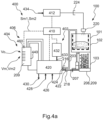
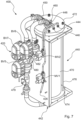
- Fig. 4a now illustrates a permeability test device 400 schematically, as it is connected to the bioreactor 100 according to Fig.1 connected.
- Fig. 4b similarly shows a mobile bioreactor cleaning system 500 which uses the permeability test device 400 according to Fig. 4a is connected to the bioreactor 100.
- the permeability test device 400 has a suction unit 402 for suctioning residual liquid 208 from the liquid tank 103 through the drain line 207.
- the permeability test device 400 also comprises a liquid dosing unit 404 for dispensing a liquid with a predetermined liquid volume V0 into the filter basket 101 through a flushing line 203.
- the permeability test device 400 comprises a measuring unit 406 in which the suctioned filtered liquid volume Vm of the filtered liquid 209 is measured.
- a control unit 410 is provided which is connected to these units by signal technology.
- a cleaning unit 412 is also provided, which does not necessarily have to be part of the permeability test device 400, but can also be provided as a separate structural unit, preferably in the bioreactor cleaning system 500. This is preferred because the cleaning unit 412 in particular should also be manually operable, independently of the permeability test device 400. However, there can also be embodiments in which the cleaning unit 412 is part of the permeability test device 400.
- the continuity test device 400 in the in Fig. 4a shown schematic embodiment has a valve arrangement 420, which is only shown schematically here by a block.
- a plurality of switchable valves can be provided in the valve arrangement 420 in order to direct the corresponding liquids.
- the valve arrangement 420 has a drain line connection 422, via which the passage test device 400 is connected to the drain line 207, more precisely to the first coupling 218.
- the valve arrangement 420 has a flushing connection 424, via which the passage test device 400 is connected to the flushing line 203, more precisely to the second coupling 216.
- the first and second couplings 216, 218 are openable, so that the passage test device 400 can also be connected to other systems is.
- valve arrangement 420 has a compressed air connection 426, a fresh water connection 428 and an outlet 430, via which the valve arrangement 420 can, for example, expel sucked liquid, for example into a collecting container within the bioreactor cleaning system 500.
- the compressed air connection 426 and the fresh water connection 428 are connected internally within the bioreactor cleaning system 500 to corresponding sources not shown here.
- the continuity test device 400 also has a pump 432, which can also be controlled by the control unit 410.
- the pump 432 is preferably designed as a rotary lobe pump, which has advantages when expelling the filtered liquid volume.
- the pump 432 is connected to a vacuum port 433 of the valve assembly 420 and provides a vacuum.
- the valve arrangement 420 and the measuring unit 406 are also in signal connection with the control unit 410.
- the cleaning unit 412 also has a fresh water connection 434 and is in signal connection with the control unit 410.
- the permeability test device 400 is integrated into a bioreactor cleaning system 500.
- the bioreactor cleaning system 500 is mobile and is arranged on a trolley frame 502.
- the bioreactor cleaning system 500 has a fresh water connection 504, which can be connected to a fresh water source 506, and a voltage connection 508, which can preferably be connected to a high-voltage source in order to supply the bioreactor cleaning system 500 with voltage.
- the bioreactor cleaning system 500 has a collecting container for extracted liquid and a chemical tank for acid, for example.
- the bioreactor cleaning system 500 is connected to the bioreactor 100 as shown in Fig. 4b shown.
- a fill level sensor 520 is read. This outputs an 80% value and a 95% value, which each indicate the corresponding fill level of the solids tank 102.
- the filter cake 104 in the filter basket 101 is then usually first manually removed via the flushing line 203. There you will often find items such as paper, feminine hygiene products, some cutlery, lost objects such as watches, glasses, etc. All of this is first manually vacuumed off and then a manually controlled mechanical cleaning is carried out using the cleaning nozzle 220 to loosen the filter cake 104. The fluid which then swells up is also vacuumed off via the flushing line 203.
- the method according to the invention is carried out and the permeability is first determined.
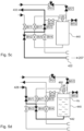
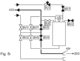
- the exact operation of the continuity test device 400 will now be discussed with reference to 5a - 5i are described, in which further elements of the passage test device 400, and in particular valves of the valve arrangement 420, are shown in detail.
- Fig. 5a the passage test device 400 is initially shown in an initial state.
- the control unit 410 In contrast to the Fig.4 are not shown the control unit 410, the pump 432 and the cleaning unit 412. Nevertheless, it should be understood that these elements can be present. Instead of the pump 432, only the vacuum connection 433 is shown and all valves and sensors described below are connected to the control unit 410.
- the measuring unit 406 here includes a measuring cylinder 440, which is also already in Fig. 4 is shown.
- the measuring cylinder 440 has a lower liquid connection 442, a compressed air inlet 444, an air outlet 446, a vacuum connection 448 and a measuring liquid inlet 450.
- the lower liquid connection 442 is arranged on the underside of the vertically aligned measuring cylinder 440, the other connections on the top.
- the radial side walls of the measuring cylinder 440 are preferably formed from a transparent material, in particular glass or Plexiglas.
- a fill level sensor is also provided on the top, which is designed here as a non-contact distance sensor 460 and is also connected to the control unit 410 and provides the first and second measurement signals SM1, SM2 there.
- the distance sensor 460 measures a distance between it and a liquid surface.
- the distance sensor 460 is designed as an ultrasonic sensor, radar sensor, laser sensor or LiDAR sensor.
- a baffle plate 443 is additionally arranged inside the measuring cylinder 440, which is intended to prevent liquid, which is supplied through the lower liquid connection 442, from splashing up to the distance sensor 460. In this way, contamination of the distance sensor 460 is to be prevented.
- the compressed air inlet 444 can be used to blow out a dirty distance sensor 460.
- the baffle 443 is not shown in the following figures, it should be understood that it is nonetheless present.
- the valve arrangement 420 here comprises several valves, namely a first valve BV1, a second valve BV2, a third valve BV3, a fourth valve BV4, a fifth valve BV5, a sixth valve BV6, a seventh valve BV7 and a first pneumatic valve PV1, a first throttle MV1 and a compensation valve MV2.
- the throttle MV1 is arranged in a compressed air line between the compressed air connection 426 and the compressed air inlet 444. It can be set manually.
- the throttle MV1 is usually open.
- the compensation valve MV2 is used to exhaust air from the measuring cylinder 440 when it is filled with liquid.
- the compensation valve MV2 is also open during normal operation. All other valves are initially closed, as shown by their unfilled representation of the valves. A full-surface representation of the valves indicates an opening.
- a first step the flushing line 203 is first filled with water in order to fill the flushing line 203 so that the subsequent defined volume can be filled into the bioreactor 100 without losses.
- the first valve BV1 and the fourth valve BV4 are opened so that water can get from the fresh water connection 428 into the flushing line 203.
- the valves BV1 and BV4 are then closed again and a predetermined time is waited so that the remaining water can flow through the sinter plate 201.
- a first waiting time is preferably waited here, which is in the range between 10 and 1000 seconds, preferably 100 to 500 seconds, preferably approximately in the range of 250 seconds.
- the suction unit 402 is controlled by means of the electronic control unit 410 in order to remove residual liquid 208 that was previously present in the liquid tank 103 or only by supplying water, as with reference to Fig. 5b described, inserted, sucked off.
- the suction takes place through the drain line 207, so that the third valve BV3 and the second valve BF2 are now opened, so that the drain line connection 422 is connected to the vacuum connection 433.
- This residual liquid is then simply dispensed via the outlet 430.
- the process can continue without a waiting time, namely by controlling the liquid dosing unit 404 by means of the electronic control unit 410 to take up a predetermined liquid volume V0 in the measuring cylinder 440.
- the predetermined liquid volume V0 is in the Fig. 5a and 4a drawn in.
- the first valve BV1 and the fifth valve BV5 are then opened so that fresh water can flow from the fresh water connection 428 to the lower liquid connection 442 of the measuring cylinder 440 and enter the measuring cylinder 440.
- air that was previously in the measuring cylinder 440 flows out of the measuring cylinder 440 via the outlet valve MV2.
- the reaching of the predetermined liquid volume V0 is preferably determined by means of the distance sensor 460. This provides a corresponding signal SF, which represents a fill level, to the control unit 410, which closes the first valve BV1 and the fifth valve BV5 when the predetermined liquid volume V0 is reached.
- This step can now be followed by another waiting period. However, this is not absolutely necessary.
- the waiting time depends largely on whether liquid should already be added to the filter basket 101 or not.
- Fig. 5e Dispensing the predetermined liquid volume V0 into the filter basket 101 is in Fig. 5e illustrated.
- the compensation valve MV2 is first closed, then the valves BV4 and BV5 are opened, so that the lower liquid connection 442 of the measuring cylinder 440 is connected in a fluid-conducting manner to the flushing connection 424 and thus to the flushing line 203.
- the first pneumatic valve PV1 is then opened so that compressed air can flow into the measuring cylinder 440 via the compressed air inlet 444 and can thus press out the volume V0 of the liquid located therein.
- the throttle MV1 must be taken into account here.
- this waiting time can correspond to the first waiting time and can also be in the range between 10 and 1000 seconds.
- the dimensioning of this second waiting time essentially depends on how quickly the added liquid flows through the filter basket 101, in particular through the sinter plate 201. If, for example, a very large area is provided, the waiting time can also be shorter. In the exemplary embodiment shown, it is preferably 250 seconds.
- This waiting time corresponds to the duration of the predetermined filter time interval tZ (cf. Fig. 8 ), which begins from the filter start time (tF). This is when the levy is made in accordance with Fig. 5e was stopped.
- the sixth valve BV6 is opened in order to be able to apply vacuum to the vacuum port 448, while the compensation valve MV2 is still closed.
- the second valve BV2 and the seventh valve BV7 are opened, so that the measuring liquid inlet 450 is also open. Since there is now negative pressure within the measuring cylinder 440, filtered liquid 209 is sucked into the measuring cylinder 440 via the measuring liquid inlet 450 via the drain line 207 and the drain line connection.
- suction can either take place after a predetermined period of time or depending on whether air is being sucked in or not. This has already been described above. For example, suction takes place here for a period of around 50 seconds in order to convey the filtered liquid into the measuring cylinder 440. This takes place here without throttling.
- the distance sensor 460 is preferably cleaned in a further step. This is in Fig. 5g illustrated.
- the second valve BV2, the sixth valve BV6 and the seventh valve BV7 are closed again, but the compensation valve MV2 is opened.
- the first pneumatic valve PV1 opened for a short period of time so that compressed air can flow into the measuring cylinder 440 via the compressed air connection 426 and the compressed air inlet 444 and thus blow the distance sensor 460 free.
- the distance between this and the surface of the liquid 209 within the measuring cylinder 440 is then measured using the distance sensor 460.
- the fill level Vm is determined and a corresponding signal SM1 is provided to the control unit 410.
- the control unit 410 then forms a first permeability quotient QD1 (cf. Fig. 8b ) from the volume Vm of the liquid that was sucked out and the volume V0 of the liquid that was put into the filter basket 101.
- the volume Vm of the sucked out liquid is less than the volume V0 of the added liquid, which means that liquid still remains on the sintered plate 201 and is, for example, sucked up within the filter cake 104.
- this permeability quotient QD1 falls below a first permeability limit value DG1, which can be 0.8, for example, the cleaning unit 412 is activated. This can be done by means of the control unit 410, even if this is not absolutely necessary. It can also be provided that a further control unit 410 controls the cleaning unit 412.
- the measuring cylinder 440 must be emptied. This is in Fig. 5h shown.
- the compensation valve MV2 remains open, while the third valve BV3 and the fifth valve BV5 are also opened.
- the lower liquid connection 442 is connected to the vacuum connection 433, so that the liquid 209 is sucked out. It can then in turn be delivered via the outlet 430. This suction can then stop if air is still being sucked in, or if the distance sensor 460 detects that there is no longer any liquid in the measuring cylinder 440.
- the flushing line 203 is then drained by connecting the flushing connection 424 to the vacuum connection 433.
- the third valve BV3 and the fourth valve BV4 are opened.
- a further permeability test can be carried out.
- the same steps are carried out here, again preferably specifying the same predetermined volume V0.
- a second volume of filtered liquid VM2 is then detected, which is generally larger than the first volume VM of the filtered liquid in the first cycle.
- the waiting times are also preferably identical, but can also be shortened for the second cycle.
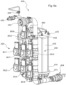
- the Fig. 6a and 6b now show a first constructive implementation of the continuity test device 400, as in the Fig. 4 and 5 described.
- the ones in the Fig. 6a , 6b The passage test device 400 shown is intended to expand existing bioreactor cleaning systems or suction systems without a passage tester. It can be integrated into such systems as a retrofit and vacuum, water and compressed air can be supplied from external sources.
- the same and similar elements are designated with the same reference numbers as in the previous figures, so that full reference is made to the above description for these elements.
- the control unit 410, the cleaning unit 412 and the pump 432 are omitted.
- the structure corresponds to Fig. 6a , 6b the the 5a - 5i .
- the individual valves BV1 - BV7, MV1, MV2, PV1 are connected to each other by means of liquid or compressed air lines, which can carry either air or liquid.
- the flushing connection 424 and the outflow line connection 422 are each designed as Kamlok couplings 425, 423 in order to be connected to corresponding connections on the bioreactor 100 or a track-bound vehicle in which the bioreactor 100 is installed.
- the measuring cylinder 400 is here formed from a cylindrical transparent tube piece 470, which is closed at its upper and lower ends with a cover 472 or base 474. Lid 472 and base 474 are clamped against each other via clamping screws 476 (only one of which has a reference number).
- the connections 448, 450, 444, 446 and the distance sensor 460 are arranged and fastened in the cover 472.
- the lower liquid connection 442 is provided in the base 474.
- a ball valve 478 is installed as a throttle 479 in a line between the fresh water inlet 442 and the fifth valve BV5. It has been found that residual liquid that has been sucked out, fresh water and any liquid that is introduced into the measuring cylinder 440 via the lower liquid connection 442 should not be introduced at too high a pressure in order to avoid contamination of the distance sensor 460.
- the throttle 479 it is also conceivable and preferred to design the throttle 479 to be electronically controllable. In the embodiment shown here However, it is purely mechanical and can be adjusted manually by an operator.
- Fig. 7 now shows a second practical implementation of the continuity test device 400, which is particularly suitable for installation in the in Fig. 4b
- Bioreactor cleaning system 500 shown is suitable with a higher degree of automation.
- the valve arrangement 420 in particular is designed differently than in the previous exemplary embodiment ( Fig. 6a , 6b ) as well as the connections.
- the same and similar elements are again provided with the same reference numbers, so that full reference is made to the above description.
- valves BV5 and BV7 are present here.
- the other valves are present or replaced, so that the provision of these three valves BV5, BV6, BV7 is sufficient here.
- a liquid connection 480 is provided between the valves BV5 and BV7, to which the liquid flow between the valves BV1 and BV2 or BV3 and BV4 (cf. Fig. 5a ) branching lines. This means that a T-piece or distributor piece should first be connected to the liquid connection 480 in order to then connect the corresponding lines.
- the liquid connection 480 therefore takes in both fresh water and liquid from the bioreactor and passes this on to either the lower liquid connection 442 or the liquid inlet 450 according to the circuit of the valves BV5, BV7.
- the valve BV6 is provided with a vacuum connection 482 which is connected in a corresponding manner to the line connecting the vacuum connection 433 and the third valve BV3 according to Fig. 5a connects, can be connected.
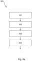
- the method 300 for automated cleaning of the filter basket 101 in a bioreactor 100 is clearly illustrated. It first comprises a step of determining 301 a permeability of the filter basket 101 and then controlling 302 a cleaning unit 412 as described above in principle to carry out a cleaning process of the filter basket 101 if certain criteria are met. This can be followed by a second determination of the permeability 303 of the filter basket 101, which can be carried out identically or similarly to the first determination 301. The second determination 303 is then preferably followed by controlling 304 the cleaning unit 412. This sequence of steps is preferably carried out until a desired cleaning result has been achieved. The Cleaning steps may have been carried out prior to step 301. It is not absolutely necessary that a permeability is determined first and then a cleaning step is carried out. It is also conceivable that a cleaning step is carried out first and only then the permeability is determined.
- step 301 (determining the permeability of the filter basket 101) initially includes, in a first step, controlling 310 of the suction unit 102 by means of the electronic control unit 410 for suctioning the residual liquid 208 from the liquid tank 103. Subsequently, as with reference to 5a - 5i described, first the predetermined volume of liquid is recorded in the measuring cylinder 440. This is done in step 312. The liquid metering unit 404 is then activated in step 314 in order to dispense the predetermined liquid volume V0 into the filter basket 101. It should be understood that step 312 is not absolutely necessary.
- the predetermined liquid volume V0 is dispensed directly into the filter basket 101 without prior measurement in the measuring cylinder 440.
- the dispensing of the liquid is then stopped in step 316. This takes place at a filter start time tF. What is important in step 314 is that the liquid is not added to the filter basket 101 too quickly, but rather at a delivery rate as described above. If the filter start time tF is determined by terminating the dispensing of the liquid, a predetermined filter time interval tZ is first waited in step 318 in order to give the liquid that was added to the filter basket 101 time to pass through the filter cake 104. Subsequently, in step 320, the suction unit 402 is activated in order to empty the liquid tank 103 using it.
- the filtered liquid volume 209 which has passed through the filter basket 101 and collects in the liquid tank 103, is located in the liquid tank 103.
- this extracted filtered liquid volume 209 is recorded in the measuring cylinder 440.
- the volume VM of the extracted filtered liquid volume 209 is measured.
- a corresponding first measurement signal SM1 representing the first measurement result is sent (step 326) to the control unit 410.
- this forms a first permeability quotient QD1 from the volume Vm, which was previously measured, and the volume V0 , which was initially placed in the filter basket 101.
- the control unit 410 compares the first permeability quotient QD1 with a first predetermined permeability limit value DG1. A case distinction is then made: If the first permeability quotient QD1 falls below the first permeability limit value DG1, the Cleaning unit activated 332. However, if the first permeability quotient exceeds the first permeability limit value DG1 or corresponds to this, the method is preferably ended. At the same time it can be provided that in step 334 a signal is output which indicates that the desired cleaning result has been achieved. Cleaning then no longer needs to be carried out.
- step 302. If the first permeability quotient QD1 falls below the first permeability limit value DG1 by a first amount, a chemical cleaning process is preferably carried out. However, if the first permeability quotient QD1 falls below the first permeability limit value DG1 by a second value, a mechanical cleaning process is carried out. How the first and second values are selected is preferably specified by the manufacturer or by the operator of the bioreactor 100. The exact amounts of these values depend on the type of bioreactor 100, the type of filter basket 101 and other parameters that are not the subject of the invention here.
- the first cleaning process in step 302 may be followed by a second determination of the permeability 303, as described with reference to Fig. 8a
- the second determination of the permeability 303 is now described with reference to Fig. 8c described in detail.
- a step 340 the suction unit 402 is controlled by means of the electronic control unit 410 to suck out the residual liquid 208 then present in the liquid tank 103.
- This is analogous to step 310 and can be carried out identically.
- the suction in step 340 can be carried out identically to the suction in step 310.
- a predetermined volume of liquid V0 is then added to the measuring cylinder 440.
- the predetermined liquid volume V0 recorded here in step 342 may correspond to the predetermined liquid volume V0 recorded in step 312. However, a different predetermined liquid volume V0 can also be used.
- step 344 the liquid metering unit 404 is then controlled by means of the electronic control unit 410 in order to dispense the predetermined liquid volume V0 into the filter basket 101.
- step 346 the delivery is then ended, again at a filter start time tF. Afterward is waited in step 348 for a predetermined filter time interval tZ.
- the filter time interval tZ in step 348 may be a second filter time interval that is different from the first filter time interval tZ in step 318.
- the filter time intervals tZ are preferably chosen to be identical.
- the suction unit 402 is activated by means of the control unit 410 (step 350) in order to suction the filtered liquid volume 209 from the liquid tank 103.
- the suction can again be carried out here for the same period of time as was done in step 320.
- the suctioned liquid volume is then again recorded in the measuring cylinder 440.
- the recorded volume Vm2 is measured.
- the volume Vm2 recorded in the second pass is usually slightly larger than the volume Vm recorded in the first pass, since the filter basket has been cleaned in the meantime in step 302.
- a second measurement signal SM2 is then sent to the control unit 410, which represents a second measurement result.
- a second permeability quotient QD2 is formed by the control unit.
- the control unit uses the volume Vm2 of the previously extracted filtered liquid volume to the volume V0 that was placed in the filter basket in step 344.
- the second permeability quotient QD2 formed in this way is then compared with a second predetermined permeability limit value DG2.
- a case distinction then takes place again. If it is determined that the second permeability limit QD2 falls below the second permeability limit DG2, the cleaning process is started in step 304 (cf. Fig. 8a ) carried out as described above. Otherwise, a signal can again be output in step 362, which indicates that the desired cleaning result has been achieved.
- cleaning step 304 a distinction can be made between mechanical and chemical cleaning.
Landscapes
- Chemical & Material Sciences (AREA)
- Life Sciences & Earth Sciences (AREA)
- Chemical Kinetics & Catalysis (AREA)
- Hydrology & Water Resources (AREA)
- Engineering & Computer Science (AREA)
- Environmental & Geological Engineering (AREA)
- Water Supply & Treatment (AREA)
- Organic Chemistry (AREA)
- Health & Medical Sciences (AREA)
- Biodiversity & Conservation Biology (AREA)
- Microbiology (AREA)
- Physics & Mathematics (AREA)
- Dispersion Chemistry (AREA)
- Analytical Chemistry (AREA)
- Biochemistry (AREA)
- General Health & Medical Sciences (AREA)
- General Physics & Mathematics (AREA)
- Immunology (AREA)
- Pathology (AREA)
- Molecular Biology (AREA)
- General Chemical & Material Sciences (AREA)
- Apparatus Associated With Microorganisms And Enzymes (AREA)
- Filtration Of Liquid (AREA)
- Sampling And Sample Adjustment (AREA)
Applications Claiming Priority (2)
| Application Number | Priority Date | Filing Date | Title |
|---|---|---|---|
| DE102020112317.5A DE102020112317B4 (de) | 2020-05-06 | 2020-05-06 | Verfahren und Vorrichtung zur automatisierten Reinigung eines Filterkorbs in einem Feststofftank eines Bioreaktors |
| PCT/EP2021/061563 WO2021224179A1 (de) | 2020-05-06 | 2021-05-03 | Automatisierter durchlasstest für einen filterkorb |
Publications (3)
| Publication Number | Publication Date |
|---|---|
| EP4146367A1 EP4146367A1 (de) | 2023-03-15 |
| EP4146367C0 EP4146367C0 (de) | 2024-04-03 |
| EP4146367B1 true EP4146367B1 (de) | 2024-04-03 |
Family
ID=75870598
Family Applications (1)
| Application Number | Title | Priority Date | Filing Date |
|---|---|---|---|
| EP21724224.7A Active EP4146367B1 (de) | 2020-05-06 | 2021-05-03 | Automatisierter durchlasstest für einen filterkorb |
Country Status (8)
| Country | Link |
|---|---|
| US (1) | US12158408B2 (pl) |
| EP (1) | EP4146367B1 (pl) |
| KR (1) | KR20230008776A (pl) |
| CN (1) | CN115803093A (pl) |
| DE (1) | DE102020112317B4 (pl) |
| ES (1) | ES2980904T3 (pl) |
| PL (1) | PL4146367T3 (pl) |
| WO (1) | WO2021224179A1 (pl) |
Families Citing this family (4)
| Publication number | Priority date | Publication date | Assignee | Title |
|---|---|---|---|---|
| JP2022068575A (ja) * | 2020-10-22 | 2022-05-10 | 株式会社ディスコ | 洗浄装置 |
| CN115032133B (zh) * | 2022-06-06 | 2024-06-04 | 中国中医科学院中药研究所 | 一种内皮细胞单层通透性检测实验装置 |
| DE102022213580A1 (de) * | 2022-12-13 | 2024-06-13 | It Inventor Gmbh | Verfahren und Vorrichtung zur Überwachung einer Anlage der Luft- und Klimatechnik |
| DE102023102188B3 (de) * | 2023-01-30 | 2024-07-25 | Taprogge Gesellschaft Mbh | Vorrichtung, System und Verfahren zum Erzeugen eines Druckluftimpulses |
Family Cites Families (10)
| Publication number | Priority date | Publication date | Assignee | Title |
|---|---|---|---|---|
| DE19607740A1 (de) | 1996-02-29 | 1997-09-04 | Gessner & Co Gmbh | Verfahren zur Steuerung von Filtrationsanlagen |
| DE102007007894A1 (de) * | 2007-02-14 | 2008-08-21 | Technische Universität Berlin | Verfahren zur Wiederherstellung optimaler Durchströmungseigenschaften von Membranfiltern |
| CN101284213B (zh) * | 2008-05-30 | 2011-08-03 | 北京汉青天朗水处理科技有限公司 | 一种清洗膜分离设备的方法及装置 |
| EP2184095B1 (en) | 2008-11-11 | 2012-01-11 | Millipore Corporation | System and method for filtration of liquids |
| KR20110001354A (ko) * | 2009-06-30 | 2011-01-06 | 웅진코웨이주식회사 | 기능수 정수기 및 이에 사용되는 기능수 생성 제어방법 |
| ITRM20120086U1 (it) * | 2012-05-29 | 2013-11-30 | Planus S P A | Serbatoio di raccolta per acque reflue avente un alloggiamento con accesso e rimozione semplificata della pompa trituratrice e dei relativi dispositivi elettrici |
| KR101542617B1 (ko) * | 2012-12-03 | 2015-08-06 | 삼성에스디아이 주식회사 | 분리막 세정 시스템 및 이를 이용한 분리막 세정 방법 |
| CN105597396A (zh) * | 2016-03-09 | 2016-05-25 | 李亚娟 | 智能固液分离装置 |
| CN110772853A (zh) * | 2019-10-31 | 2020-02-11 | 广东溢达纺织有限公司 | 过滤设备及废热水热回收方法 |
| CN110790452B (zh) * | 2019-11-01 | 2021-10-26 | 淮安信息职业技术学院 | 一种基于plc控制的污水净化处理装置 |
-
2020
- 2020-05-06 DE DE102020112317.5A patent/DE102020112317B4/de active Active
-
2021
- 2021-05-03 WO PCT/EP2021/061563 patent/WO2021224179A1/de not_active Ceased
- 2021-05-03 PL PL21724224.7T patent/PL4146367T3/pl unknown
- 2021-05-03 US US17/922,989 patent/US12158408B2/en active Active
- 2021-05-03 KR KR1020227042428A patent/KR20230008776A/ko active Pending
- 2021-05-03 CN CN202180046166.5A patent/CN115803093A/zh active Pending
- 2021-05-03 ES ES21724224T patent/ES2980904T3/es active Active
- 2021-05-03 EP EP21724224.7A patent/EP4146367B1/de active Active
Also Published As
| Publication number | Publication date |
|---|---|
| DE102020112317B4 (de) | 2022-03-10 |
| EP4146367C0 (de) | 2024-04-03 |
| EP4146367A1 (de) | 2023-03-15 |
| WO2021224179A1 (de) | 2021-11-11 |
| DE102020112317A1 (de) | 2021-11-11 |
| CN115803093A (zh) | 2023-03-14 |
| ES2980904T3 (es) | 2024-10-03 |
| US20230175947A1 (en) | 2023-06-08 |
| US12158408B2 (en) | 2024-12-03 |
| KR20230008776A (ko) | 2023-01-16 |
| PL4146367T3 (pl) | 2024-08-19 |
Similar Documents
| Publication | Publication Date | Title |
|---|---|---|
| EP4146367B1 (de) | Automatisierter durchlasstest für einen filterkorb | |
| EP0855473B1 (de) | Vorrichtung und Verfahren zur Nutzung von Grauwasser | |
| DE4112888A1 (de) | Vakuum-toilettensystem | |
| AT508458A1 (de) | Vorrichtung und verfahren zum reinigen von abwasserleitungen von unterdrucktoilettenanlagen | |
| EP3209834A1 (de) | Sanitäreinheit mit überwachungseinrichtung | |
| EP3456891B1 (de) | Fäkalientank für eine sanitäreinrichtung | |
| DE102012023683A1 (de) | Sanitäreinheit, die zur Wiederverwertung von Grauwasser ausgebildet ist | |
| EP4179061A1 (de) | Bioreaktorreinigungsanlage mit einem säuretank sowie einer einrichtung zum neutralisieren der säure | |
| WO2022013194A1 (de) | Bioreaktorreinigungsanlage für bioreaktoren in schienenfahrzeugen | |
| DE102009051619A1 (de) | Pflegevorrichtung für dentaltechnische Geräte | |
| DE69629867T2 (de) | Verfahren zum Zuführen und Auffangen von Lösungen | |
| EP3487743A1 (de) | Grauwasseraufbereitungsvorrichtung für ein schienenfahrzeug | |
| DE4205936B4 (de) | Abscheideeinrichtung | |
| EP3487742A1 (de) | Grauwasseraufbereitungsvorrichtung für ein schienenfahrzeug | |
| DE4243239A1 (de) | Vorrichtung zum Abscheiden von Amalgam | |
| EP0852129B1 (de) | Verfahren und Vorrichtung zum Entleeren eines Sammelbehälters für fliessfähige Exkremente an einem medizinischen, insbesondere zahnmedizinischen Behandlungsplatz | |
| EP1516682B1 (de) | Verfahren und Vorrichtung zum Spülen und Entleeren eines mit feststoffartigen Rückständen gefüllten Rückstandtanks einer biologischen Kläranlage | |
| DE102014016453B4 (de) | Filtersystem, seine Verwendung sowie ein Verfahren zur Filtration von einer Lauge | |
| DE202020104037U1 (de) | Bioreaktorreinigungsanlage für Bioreaktoren in Schienenfahrzeugen | |
| WO2022106135A1 (de) | Vakuumtoilette | |
| DE102016217991B4 (de) | Grauwasseraufbereitungsvorrichtung für ein Schienenfahrzeug | |
| WO2024041934A1 (de) | Vorrichtung zur reinigung von kraftstoff und deren verwendung | |
| CH715406B1 (de) | Brunnenstube. | |
| DE29518147U1 (de) | Vorrichtung zur Nutzung von Abwasser als Spülwasser | |
| DE202011105808U1 (de) | Vorrichtung zur normgerechten Bestimmung eines Schlammvolumens |
Legal Events
| Date | Code | Title | Description |
|---|---|---|---|
| STAA | Information on the status of an ep patent application or granted ep patent |
Free format text: STATUS: UNKNOWN |
|
| STAA | Information on the status of an ep patent application or granted ep patent |
Free format text: STATUS: THE INTERNATIONAL PUBLICATION HAS BEEN MADE |
|
| PUAI | Public reference made under article 153(3) epc to a published international application that has entered the european phase |
Free format text: ORIGINAL CODE: 0009012 |
|
| STAA | Information on the status of an ep patent application or granted ep patent |
Free format text: STATUS: REQUEST FOR EXAMINATION WAS MADE |
|
| 17P | Request for examination filed |
Effective date: 20221206 |
|
| AK | Designated contracting states |
Kind code of ref document: A1 Designated state(s): AL AT BE BG CH CY CZ DE DK EE ES FI FR GB GR HR HU IE IS IT LI LT LU LV MC MK MT NL NO PL PT RO RS SE SI SK SM TR |
|
| DAV | Request for validation of the european patent (deleted) | ||
| DAX | Request for extension of the european patent (deleted) | ||
| GRAP | Despatch of communication of intention to grant a patent |
Free format text: ORIGINAL CODE: EPIDOSNIGR1 |
|
| STAA | Information on the status of an ep patent application or granted ep patent |
Free format text: STATUS: GRANT OF PATENT IS INTENDED |
|
| INTG | Intention to grant announced |
Effective date: 20231124 |
|
| GRAS | Grant fee paid |
Free format text: ORIGINAL CODE: EPIDOSNIGR3 |
|
| GRAA | (expected) grant |
Free format text: ORIGINAL CODE: 0009210 |
|
| STAA | Information on the status of an ep patent application or granted ep patent |
Free format text: STATUS: THE PATENT HAS BEEN GRANTED |
|
| AK | Designated contracting states |
Kind code of ref document: B1 Designated state(s): AL AT BE BG CH CY CZ DE DK EE ES FI FR GB GR HR HU IE IS IT LI LT LU LV MC MK MT NL NO PL PT RO RS SE SI SK SM TR |
|
| REG | Reference to a national code |
Ref country code: CH Ref legal event code: EP |
|
| REG | Reference to a national code |
Ref country code: DE Ref legal event code: R096 Ref document number: 502021003219 Country of ref document: DE |
|
| REG | Reference to a national code |
Ref country code: IE Ref legal event code: FG4D Free format text: LANGUAGE OF EP DOCUMENT: GERMAN |
|
| U01 | Request for unitary effect filed |
Effective date: 20240502 |
|
| U07 | Unitary effect registered |
Designated state(s): AT BE BG DE DK EE FI FR IT LT LU LV MT NL PT SE SI Effective date: 20240510 |
|
| U20 | Renewal fee for the european patent with unitary effect paid |
Year of fee payment: 4 Effective date: 20240530 |
|
| REG | Reference to a national code |
Ref country code: ES Ref legal event code: FG2A Ref document number: 2980904 Country of ref document: ES Kind code of ref document: T3 Effective date: 20241003 |
|
| PG25 | Lapsed in a contracting state [announced via postgrant information from national office to epo] |
Ref country code: IS Free format text: LAPSE BECAUSE OF FAILURE TO SUBMIT A TRANSLATION OF THE DESCRIPTION OR TO PAY THE FEE WITHIN THE PRESCRIBED TIME-LIMIT Effective date: 20240803 |
|
| PG25 | Lapsed in a contracting state [announced via postgrant information from national office to epo] |
Ref country code: HR Free format text: LAPSE BECAUSE OF FAILURE TO SUBMIT A TRANSLATION OF THE DESCRIPTION OR TO PAY THE FEE WITHIN THE PRESCRIBED TIME-LIMIT Effective date: 20240403 |
|
| PG25 | Lapsed in a contracting state [announced via postgrant information from national office to epo] |
Ref country code: GR Free format text: LAPSE BECAUSE OF FAILURE TO SUBMIT A TRANSLATION OF THE DESCRIPTION OR TO PAY THE FEE WITHIN THE PRESCRIBED TIME-LIMIT Effective date: 20240704 |
|
| PG25 | Lapsed in a contracting state [announced via postgrant information from national office to epo] |
Ref country code: CZ Free format text: LAPSE BECAUSE OF FAILURE TO SUBMIT A TRANSLATION OF THE DESCRIPTION OR TO PAY THE FEE WITHIN THE PRESCRIBED TIME-LIMIT Effective date: 20240403 |
|
| PG25 | Lapsed in a contracting state [announced via postgrant information from national office to epo] |
Ref country code: NO Free format text: LAPSE BECAUSE OF FAILURE TO SUBMIT A TRANSLATION OF THE DESCRIPTION OR TO PAY THE FEE WITHIN THE PRESCRIBED TIME-LIMIT Effective date: 20240703 Ref country code: IS Free format text: LAPSE BECAUSE OF FAILURE TO SUBMIT A TRANSLATION OF THE DESCRIPTION OR TO PAY THE FEE WITHIN THE PRESCRIBED TIME-LIMIT Effective date: 20240803 Ref country code: HR Free format text: LAPSE BECAUSE OF FAILURE TO SUBMIT A TRANSLATION OF THE DESCRIPTION OR TO PAY THE FEE WITHIN THE PRESCRIBED TIME-LIMIT Effective date: 20240403 Ref country code: GR Free format text: LAPSE BECAUSE OF FAILURE TO SUBMIT A TRANSLATION OF THE DESCRIPTION OR TO PAY THE FEE WITHIN THE PRESCRIBED TIME-LIMIT Effective date: 20240704 Ref country code: CZ Free format text: LAPSE BECAUSE OF FAILURE TO SUBMIT A TRANSLATION OF THE DESCRIPTION OR TO PAY THE FEE WITHIN THE PRESCRIBED TIME-LIMIT Effective date: 20240403 Ref country code: RS Free format text: LAPSE BECAUSE OF FAILURE TO SUBMIT A TRANSLATION OF THE DESCRIPTION OR TO PAY THE FEE WITHIN THE PRESCRIBED TIME-LIMIT Effective date: 20240703 |
|
| REG | Reference to a national code |
Ref country code: DE Ref legal event code: R097 Ref document number: 502021003219 Country of ref document: DE |
|
| PG25 | Lapsed in a contracting state [announced via postgrant information from national office to epo] |
Ref country code: RO Free format text: LAPSE BECAUSE OF FAILURE TO SUBMIT A TRANSLATION OF THE DESCRIPTION OR TO PAY THE FEE WITHIN THE PRESCRIBED TIME-LIMIT Effective date: 20240403 Ref country code: SK Free format text: LAPSE BECAUSE OF FAILURE TO SUBMIT A TRANSLATION OF THE DESCRIPTION OR TO PAY THE FEE WITHIN THE PRESCRIBED TIME-LIMIT Effective date: 20240403 |
|
| PG25 | Lapsed in a contracting state [announced via postgrant information from national office to epo] |
Ref country code: SM Free format text: LAPSE BECAUSE OF FAILURE TO SUBMIT A TRANSLATION OF THE DESCRIPTION OR TO PAY THE FEE WITHIN THE PRESCRIBED TIME-LIMIT Effective date: 20240403 |
|
| PG25 | Lapsed in a contracting state [announced via postgrant information from national office to epo] |
Ref country code: SM Free format text: LAPSE BECAUSE OF FAILURE TO SUBMIT A TRANSLATION OF THE DESCRIPTION OR TO PAY THE FEE WITHIN THE PRESCRIBED TIME-LIMIT Effective date: 20240403 Ref country code: SK Free format text: LAPSE BECAUSE OF FAILURE TO SUBMIT A TRANSLATION OF THE DESCRIPTION OR TO PAY THE FEE WITHIN THE PRESCRIBED TIME-LIMIT Effective date: 20240403 Ref country code: RO Free format text: LAPSE BECAUSE OF FAILURE TO SUBMIT A TRANSLATION OF THE DESCRIPTION OR TO PAY THE FEE WITHIN THE PRESCRIBED TIME-LIMIT Effective date: 20240403 Ref country code: MC Free format text: LAPSE BECAUSE OF FAILURE TO SUBMIT A TRANSLATION OF THE DESCRIPTION OR TO PAY THE FEE WITHIN THE PRESCRIBED TIME-LIMIT Effective date: 20240403 |
|
| PLBE | No opposition filed within time limit |
Free format text: ORIGINAL CODE: 0009261 |
|
| STAA | Information on the status of an ep patent application or granted ep patent |
Free format text: STATUS: NO OPPOSITION FILED WITHIN TIME LIMIT |
|
| 26N | No opposition filed |
Effective date: 20250106 |
|
| PG25 | Lapsed in a contracting state [announced via postgrant information from national office to epo] |
Ref country code: IE Free format text: LAPSE BECAUSE OF NON-PAYMENT OF DUE FEES Effective date: 20240503 |
|
| U20 | Renewal fee for the european patent with unitary effect paid |
Year of fee payment: 5 Effective date: 20250407 |
|
| PGFP | Annual fee paid to national office [announced via postgrant information from national office to epo] |
Ref country code: PL Payment date: 20250407 Year of fee payment: 5 |
|
| PGFP | Annual fee paid to national office [announced via postgrant information from national office to epo] |
Ref country code: GB Payment date: 20250522 Year of fee payment: 5 Ref country code: ES Payment date: 20250616 Year of fee payment: 5 |
|
| PGFP | Annual fee paid to national office [announced via postgrant information from national office to epo] |
Ref country code: CH Payment date: 20250601 Year of fee payment: 5 |
|
| PG25 | Lapsed in a contracting state [announced via postgrant information from national office to epo] |
Ref country code: CY Free format text: LAPSE BECAUSE OF FAILURE TO SUBMIT A TRANSLATION OF THE DESCRIPTION OR TO PAY THE FEE WITHIN THE PRESCRIBED TIME-LIMIT; INVALID AB INITIO Effective date: 20210503 |
|
| PG25 | Lapsed in a contracting state [announced via postgrant information from national office to epo] |
Ref country code: HU Free format text: LAPSE BECAUSE OF FAILURE TO SUBMIT A TRANSLATION OF THE DESCRIPTION OR TO PAY THE FEE WITHIN THE PRESCRIBED TIME-LIMIT; INVALID AB INITIO Effective date: 20210503 |