EP4145720A1 - Optical space communication terminal, receiver, optical space communication system, and optical space communication reception method - Google Patents
Optical space communication terminal, receiver, optical space communication system, and optical space communication reception method Download PDFInfo
- Publication number
- EP4145720A1 EP4145720A1 EP20939181.2A EP20939181A EP4145720A1 EP 4145720 A1 EP4145720 A1 EP 4145720A1 EP 20939181 A EP20939181 A EP 20939181A EP 4145720 A1 EP4145720 A1 EP 4145720A1
- Authority
- EP
- European Patent Office
- Prior art keywords
- optical
- wavelength
- space communication
- signal
- demultiplexed
- Prior art date
- Legal status (The legal status is an assumption and is not a legal conclusion. Google has not performed a legal analysis and makes no representation as to the accuracy of the status listed.)
- Pending
Links
Images



Classifications
-
- H—ELECTRICITY
- H04—ELECTRIC COMMUNICATION TECHNIQUE
- H04B—TRANSMISSION
- H04B10/00—Transmission systems employing electromagnetic waves other than radio-waves, e.g. infrared, visible or ultraviolet light, or employing corpuscular radiation, e.g. quantum communication
- H04B10/11—Arrangements specific to free-space transmission, i.e. transmission through air or vacuum
-
- H—ELECTRICITY
- H04—ELECTRIC COMMUNICATION TECHNIQUE
- H04B—TRANSMISSION
- H04B10/00—Transmission systems employing electromagnetic waves other than radio-waves, e.g. infrared, visible or ultraviolet light, or employing corpuscular radiation, e.g. quantum communication
- H04B10/11—Arrangements specific to free-space transmission, i.e. transmission through air or vacuum
- H04B10/118—Arrangements specific to free-space transmission, i.e. transmission through air or vacuum specially adapted for satellite communication
-
- H—ELECTRICITY
- H04—ELECTRIC COMMUNICATION TECHNIQUE
- H04J—MULTIPLEX COMMUNICATION
- H04J14/00—Optical multiplex systems
- H04J14/02—Wavelength-division multiplex systems
Definitions
- the present disclosure relates to an optical space communication terminal, a receiver, an optical space communication system, and an optical space communication reception method.
- Optical space communication uses a light having a shorter wavelength as a carrier than that in microwave wireless communication, and can efficiently transmit light with suppressed beam spread. Therefore, application of the optical space communication to feeder link of next-generation geostationary satellites has been studied (See, for example, Non-Patent Literature 1.
- Non-Patent Literature 1 P. Shubert et al., "System Design of a High Capacity Optical Relay Network", Proc. ICSOS 2019, S3.3 .
- Non-Patent Literature 1 in order to achieve Tbps class feeder link in the optical space communication, optical power of more than 100 W is required.
- the output of the optical amplifier is insufficient, the transmission power of the optical space communication transmitting terminal is insufficient, and accordingly, the optical power reaching the optical space communication receiving terminal is also insufficient, and the signal-to-noise ratio (SNR) of the signal demodulated from the reception signal decreases, so that the communication capacity decreases.
- SNR signal-to-noise ratio
- the present disclosure solves the above problems, and an object thereof is to obtain an optical space communication terminal, a receiver, an optical space communication system, and an optical space communication reception method capable of suppressing a decrease in communication capacity due to an insufficient output of an optical amplifier in optical space communication.
- An optical space communication terminal includes: a plurality of transmitters forming a plurality of groups and respectively transmit optical signals of wavelengths different from each other; a plurality of multiplexers each provided to each of the plurality of groups to output an optical signal obtained by wavelength-multiplexing the optical signals transmitted from transmitters belonging to said each of the plurality of groups; a plurality of optical amplifiers each provided to each of the plurality of groups to amplify the optical signal obtained by wavelength-multiplexing the optical signals; and a plurality of optical antennas each provided to each of the plurality of groups to transmit the amplified optical signal to a space, wherein optical antennas, among the plurality of optical antennas, belonging to a same group among the plurality of groups transmit the amplified optical signal in a same direction.
- a plurality of wavelengths to be wavelength-multiplexed are divided into groups, optical signals of different wavelengths are multiplexed for each of the groups, the wavelength-multiplexed optical signals are amplified, and the amplified optical signals are transmitted in the same direction for each of the groups. Therefore, transmission power of each wavelength can be increased. As a result, the optical power reaching the reception side also increases, and the SNR of the signal demodulated from the reception signal is improved, so that it is possible to suppress a decrease in the communication capacity due to the insufficient output of the optical amplifier in the optical space communication.
- FIG. 1 is a block diagram illustrating the configuration of an optical space communication system 1 according to a first embodiment.
- the optical space communication system 1 is, for example, a system that communicates optical signals in which light beams having four different wavelengths ⁇ 1 to ⁇ 4 are wavelength-multiplexed, and includes an optical space communication transmitting terminal 2 and an optical space communication receiving terminal 3.
- the optical space communication transmitting terminal 2 transmits an optical signal obtained by wavelength-multiplexing light having wavelengths ⁇ 1 to ⁇ 4.
- the optical signal is a signal obtained by mapping a transmission signal to the optical space communication receiving terminal 3 to a signal point for an optical signal.
- the optical space communication receiving terminal 3 receives an optical signal transmitted by the optical space communication transmitting terminal 2.
- the transmission signal is demapped from the signal point of the optical signal received by the optical space communication receiving terminal 3.
- the components of the optical space communication transmitting terminal 2 are divided into a group (1) and a group (2).
- An optical antenna 21a, an optical amplifier 22a, a multiplexer 23a, a transmitter 24a, and a transmitter 24b belong to the group (1).
- An optical antenna 21b, an optical amplifier 22b, a multiplexer 23b, a transmitter 24c, and a transmitter 24d belong to the group (2).
- the group (1) transmits an optical signal obtained by wavelength-multiplexing adjacent wavelength ⁇ 1 and wavelength ⁇ 2 among the four wavelengths ⁇ 1 to ⁇ 4, and the group (2) transmits an optical signal obtained by wavelength-multiplexing adjacent wavelength ⁇ 3 and wavelength ⁇ 4.
- the plurality of wavelengths to be wavelength-multiplexed those having no overlap in the spectral band of the optical signal at the interval of adjacent wavelengths are used.
- the group (1) there is no overlap between the spectral band of the optical signal having the wavelength ⁇ 1 and the spectral band of the optical signal having the wavelength ⁇ 2
- the group (2) there is no overlap between the spectral band of the optical signal having the wavelength ⁇ 3 and the spectral band of the optical signal having the wavelength ⁇ 4.
- the transmitter 24a is a coherent transmitter (Tx ( ⁇ 1)) that transmits an optical signal having a wavelength ⁇ 1
- the transmitter 24b is a coherent transmitter (Tx ( ⁇ 2)) that transmits an optical signal having a wavelength ⁇ 2.
- the multiplexer 23a generates an optical signal in which the wavelengths ⁇ 1 and ⁇ 2 are wavelength-multiplexed by multiplexing the optical signal having the wavelength ⁇ 1 and the optical signal having the wavelength ⁇ 2.
- the optical amplifier 22a amplifies the wavelength multiplexed signal generated by the multiplexer 23a.
- the transmitter 24c is a coherent transmitter (Tx ( ⁇ 3)) that transmits the optical signal having the wavelength ⁇ 3
- the transmitter 24d is a coherent transmitter (Tx ( ⁇ 4)) that transmits the optical signal having the wavelength ⁇ 4.
- the multiplexer 23b generates an optical signal in which the wavelengths ⁇ 3 and ⁇ 4 are wavelength-multiplexed by multiplexing the optical signal having the wavelength ⁇ 3 and the optical signal having the wavelength ⁇ 4.
- the optical amplifier 22b amplifies the wavelength multiplexed signal generated by the multiplexer 23b.
- the optical antenna 21a belonging to the group (1) transmits the optical signal, in which the wavelength ⁇ 1 and the wavelength ⁇ 2 are wavelength-multiplexed and which is amplified by the optical amplifier 22a, to the optical space communication receiving terminal 3.
- the optical antenna 21b belonging to the group (2) transmits the optical signal, in which the wavelength ⁇ 3 and the wavelength ⁇ 4 are wavelength-multiplexed and which is amplified by the optical amplifier 22b, to the optical space communication receiving terminal 3. That is, the optical antenna 21a and the optical antenna 21b transmit optical signals in the same direction in which a common transmission target is present.
- the optical space communication transmitting terminal 2 divides a plurality of wavelengths to be wavelength-multiplexed into N (N is an integer of 2 or more) groups, multiplexes optical signals of different wavelengths for each group, amplifies the wavelength-multiplexed optical signals, and transmits the amplified optical signals in the same direction for each group.
- N is an integer of 2 or more
- the transmission power of the signal of each wavelength becomes N times
- the signal of the optical power of N times per each wavelength is received with respect to the optical space communication receiving terminal 3. Therefore, in the optical space communication transmitting terminal 2, the SNR is improved by about N times, and a communication capacity of about N times can be achieved.
- optical signal output from the optical antenna 21a and the optical signal output from the optical antenna 21b have different wavelengths, interference is reduced. As a result, a wavelength multiplexed optical signal is transmitted to the optical space communication receiving terminal 3, similarly to the wavelength multiplexed signal transmitted by one optical antenna is transmitted.
- the output power of each optical amplifier can be lowered without changing the communication capacity as compared with the case where the optical signals having the wavelengths ⁇ 1 to ⁇ 4 are multiplexed to be one wavelength multiplexed signal, amplified by one optical amplifier, and then transmitted by one optical antenna. That is, although the transmission power of the signal of each wavelength increases, the transmission power of each optical antenna decreases, so that the optical space communication transmitting terminal 2 is effective from the viewpoint of eye safety.
- the optical space communication transmitting terminal 2 transmission systems of optical signals having close wavelengths among a plurality of wavelengths to be wavelength-multiplexed are grouped into the same group.
- the wavelength range supported by the optical amplifiers and the optical antennas belonging to the same group is narrower than those in a case where all optical signals obtained by wavelength multiplexing of a plurality of wavelengths are collectively amplified and transmitted, so that the wavelength dependency of the gain in the optical amplifiers is reduced.
- the loss of the filter is reduced. Since the wavelength range supported by the optical antenna for each group is narrowed by dividing the optical signals of the plurality of wavelengths into groups, the optical system having a simpler configuration is allowed for the optical space communication transmitting terminal 2. For example, the number of lenses for suppressing chromatic aberration can be reduced, and the number of layers of a dielectric multilayer film for preventing reflection can be reduced.
- the optical space communication receiving terminal 3 includes an optical antenna 31, an optical amplifier 32, a demultiplexer 33, a receiver 34a, a receiver 34b, a receiver 34c, and a receiver 34d.
- the optical antenna 31 collects the light transmitted from the optical space communication transmitting terminal 2 and propagating in the space.
- the optical amplifier 32 amplifies the light collected by the optical antenna 31.
- the demultiplexer 33 demultiplexes the optical signal wavelength-multiplexed with the light amplified by the optical amplifier 32 for each wavelength.
- the receiver 34a is a coherent receiver (Rx ( ⁇ 1)) that receives an optical signal having a wavelength ⁇ 1 among the optical signals demultiplexed for each wavelength by the demultiplexer 33.
- the receiver 34b is a coherent receiver (Rx ( ⁇ 2)) that receives an optical signal having a wavelength ⁇ 2 among the optical signals demultiplexed for each wavelength by the demultiplexer 33.
- the receiver 34c is a coherent receiver (Rx ( ⁇ 3)) that receives an optical signal having a wavelength ⁇ 3 among the optical signals demultiplexed for each wavelength by the demultiplexer 33.
- the receiver 34d is a coherent receiver (Rx ( ⁇ 4)) that receives an optical signal having a wavelength ⁇ 4 among the optical signals demultiplexed for each wavelength by the demultiplexer 33.
- the angle formed by two straight lines connecting the opening center of the optical antenna 21a and the opening center of the optical antenna 21b included in the optical space communication transmitting terminal 2 with the opening center of the optical antenna 31 of the optical space communication receiving terminal 3 as an apex falls within an allowable angle error range with respect to incident light in the optical space communication receiving terminal 3.
- the light transmitted by the optical antenna 21a and the optical antenna 21b included in the optical space communication transmitting terminal 2 is incident on the optical antenna 31 included in the optical space communication receiving terminal 3 at an incident angle within the allowable angle error range, and is received in the similar manner as the wavelength multiplex signal transmitted by one optical antenna.
- the angle formed by two straight lines connecting the opening center of the optical antenna 21a and the opening center of the optical antenna 21b with the opening center of the optical antenna 31 as an apex is an extremely small angle. Therefore, the angle falls, as a result, within the allowable angle error range with respect to the incident light in the optical space communication receiving terminal 3.
- the optical space communication transmitting terminal 2 performs wavelength multiplexing of optical signals of four wavelengths.
- signals of two wavelengths different from each other may be wavelength-multiplexed, or three or more wavelengths may be wavelength-multiplexed.
- the components of the optical space communication transmitting terminal 2 are divided into the group (1) and the group (2), but the components of the optical space communication transmitting terminal 2 may be divided into three or more groups.
- the number of wavelengths to be wavelength-multiplexed in each group may not be the same.
- the number of wavelengths to be wavelength-multiplexed is five, three different wavelengths of three signals may be wavelength-multiplexed in the group (1), and two different wavelengths of two signals may be wavelength-multiplexed in the group (2).
- the optical space communication transmitting terminal 2 divides a plurality of wavelengths to be wavelength-multiplexed into groups, multiplexes optical signals having different wavelengths for each group, amplifies the wavelength-multiplexed optical signals, and transmits the amplified optical signals in the same direction for each group.
- the optical space communication transmitting terminal 2 can increase the transmission power of each wavelength, and accordingly, the optical power reaching the reception side also increases, and the SNR of the signal demodulated from the reception signal is improved, so that it is possible to suppress a decrease in the communication capacity due to the insufficient output of the optical amplifier in the optical space communication.
- an angle formed by two straight lines connecting the opening center of the optical antenna 21a and the opening center of the optical antenna 21b included in the optical space communication transmitting terminal 2 with the opening center of the optical antenna 31 of the optical space communication receiving terminal 3 as an apex falls within an allowable angle error range with respect to the incident light in the optical space communication reception terminal 3.
- the optical space communication receiving terminal 3 can receive the light transmitted by the optical antenna 21a and the optical antenna 21b in the similar manner as the light transmitted by one optical antenna.
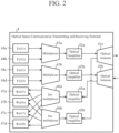
- FIG. 2 is a block diagram illustrating the configuration of an optical space communication transmitting and receiving terminal 4 which is an optical space communication terminal according to a second embodiment.
- the optical space communication transmitting and receiving terminal 4 is an optical space communication terminal that transmits an optical signal obtained by wavelength-multiplexing light having wavelengths ⁇ 1 to ⁇ 4 and receives an optical signal obtained by wavelength-multiplexing light having wavelengths ⁇ 5 to ⁇ 8, and transmits and receives the optical signal using an optical antenna 41a and an optical antenna 41b.
- the optical space communication transmitting and receiving terminal 4 includes an optical amplifier 42a, an optical amplifier 42b, a multiplexer 43a, a multiplexer 43b, a transmitter 44a, a transmitter 44b, a transmitter 44c, and a transmitter 44d as components that transmit optical signals, and includes an optical amplifier 45a, an optical amplifier 45b, a demultiplexer 46a, a demultiplexer 46b, a receiver 47a, a receiver 47b, a receiver 47c, and a receiver 47d as components that receive optical signals.
- Components that transmit optical signals in the optical space communication transmitting and receiving terminal 4 are divided into a group (1) and a group (2) as in the first embodiment.
- the optical antenna 41a, the optical amplifier 42a, the multiplexer 43a, the transmitter 44a, and the transmitter 44b belong to the group (1).
- the optical antenna 41b, the optical amplifier 42b, the multiplexer 43b, the transmitter 44c, and the transmitter 44d belong to the group (2).
- the group (1) transmits an optical signal obtained by wavelength-multiplexing adjacent wavelengths ⁇ 1 and ⁇ 2 among the four wavelengths ⁇ 1 to ⁇ 4.
- the group (2) transmits an optical signal obtained by wavelength-multiplexing adjacent wavelengths ⁇ 3 and ⁇ 4.
- the plurality of wavelengths to be wavelength-multiplexed those having no overlap in the spectral band of the optical signal between adjacent wavelengths are used as in the first embodiment.
- the group (1) there is no overlap between the spectral band of the optical signal having the wavelength ⁇ 1 and the spectral band of the optical signal having the wavelength ⁇ 2
- the group (2) there is no overlap between the spectral band of the optical signal having the wavelength ⁇ 3 and the spectral band of the optical signal having the wavelength ⁇ 4.
- the transmitter 44a is a coherent transmitter (Tx ( ⁇ 1)) that transmits an optical signal having a wavelength ⁇ 1
- the transmitter 44b is a coherent transmitter (Tx ( ⁇ 2)) that transmits an optical signal having a wavelength ⁇ 2.
- the multiplexer 43a multiplexes the optical signal having the wavelength ⁇ 1 and the optical signal having the wavelength ⁇ 2 to generate an optical signal in which the wavelengths ⁇ 1 and ⁇ 2 are wavelength-multiplexed.
- the optical amplifier 42a amplifies the wavelength multiplexed signal generated by the multiplexer 43a.
- the transmitter 44c is a coherent transmitter (Tx ( ⁇ 3)) that transmits the optical signal having the wavelength ⁇ 3
- the transmitter 44d is a coherent transmitter (Tx ( ⁇ 4)) that transmits the optical signal having the wavelength ⁇ 4.
- the multiplexer 43b multiplexes the optical signal having the wavelength ⁇ 3 and the optical signal having the wavelength ⁇ 4 to generate an optical signal in which the wavelengths ⁇ 3 and ⁇ 4 are wavelength-multiplexed.
- the optical amplifier 42b amplifies the wavelength multiplexed signal generated by the multiplexer 43b.
- the optical antenna 41a belonging to the group (1) transmits an optical signal, in which the wavelength ⁇ 1 and the wavelength ⁇ 2 amplified by the optical amplifier 42a are wavelength-multiplexed.
- the optical antenna 41b belonging to the group (2) transmits an optical signal in which the wavelength ⁇ 3 and the wavelength ⁇ 4 amplified by the optical amplifier 42b are wavelength-multiplexed. That is, the optical antenna 41a and the optical antenna 41b transmit optical signals in the same direction in which a common transmission target is present.
- the optical space communication transmitting and receiving terminal 4 divides a plurality of wavelengths to be wavelength-multiplexed into N (N is an integer of 2 or more) groups, multiplexes optical signals of different wavelengths for each group, amplifies the wavelength-multiplexed optical signals, and transmits the amplified optical signals group in the same direction for each.
- N is an integer of 2 or more
- the transmission power of the signal of each wavelength becomes N times, and the signal of the optical power of N times per wavelength is received on the reception side. Therefore, in the optical space communication transmitting and receiving terminal 4, the SNR is improved by about N times, and a communication capacity of about N times can be achieved.
- the optical antenna 41a and the optical antenna 41b collect the light propagating in the space. For example, in a case where the communication distance to the optical space communication transmitting and receiving terminal 4 is long, the light that has propagated through the space and reached the optical space communication transmitting and receiving terminal 4 is sufficiently spread, and thus enters the plurality of optical antennas.
- the optical amplifier 45a amplifies the light collected by the optical antenna 41b
- the optical amplifier 45b amplifies the light collected by the optical antenna 41a.
- the demultiplexer 46a demultiplexes the optical signal for each wavelength wavelength-multiplexed with the light amplified by the optical amplifier 45a
- the demultiplexer 46b demultiplexes the optical signal for each wavelength wavelength-multiplexed with the light amplified by the optical amplifier 45b.
- the receiver 47a is a coherent receiver (Rx ( ⁇ 5)) that receives the optical signal having the wavelength ⁇ 5 among the optical signals demultiplexed for each wavelength by the demultiplexer 46a and receives the optical signal having the wavelength ⁇ 5 among the optical signals demultiplexed for each wavelength by the demultiplexer 46b.
- the receiver 47b is a coherent receiver (Rx ( ⁇ 6)) that receives the optical signal having the wavelength ⁇ 6 among the optical signals demultiplexed for each wavelength by the demultiplexer 46a and receives the optical signal having the wavelength ⁇ 6 among the optical signals demultiplexed for each wavelength by the demultiplexer 46b.
- the receiver 47c is a coherent receiver (Rx ( ⁇ 7)) that receives the optical signal having the wavelength ⁇ 7 among the optical signals demultiplexed for each wavelength by the demultiplexer 46a and receives the optical signal having the wavelength ⁇ 7 among the optical signals demultiplexed for each wavelength by the demultiplexer 46b.
- the receiver 47d is a coherent receiver (Rx ( ⁇ 8)) that receives the optical signal having the wavelength ⁇ 8 among the optical signals demultiplexed for each wavelength by the demultiplexer 46a and receives the optical signal having the wavelength ⁇ 8 among the optical signals demultiplexed for each wavelength by the demultiplexer 46b.
- FIG. 3 is a block diagram illustrating the configuration of the receivers 47a to 47d.
- the receivers 47a to 47d are coherent receivers that receive the optical signals demultiplexed by the demultiplexer 46a and the demultiplexer 46b.
- the receivers 47a to 47d each include a coherent detector 471a, a coherent detector 471b, an ADC 472, a MISO equalization processing unit 473, a phase difference compensating unit 474, and a demapping unit 475.
- the MISO equalization processing unit 473, the phase difference compensating unit 474, and the demapping unit 475 are functional components included in a digital signal processing circuit connected to the ADC 472.
- the coherent detector 471a and the coherent detector 471b are detectors that convert an optical signal having a wavelength demultiplexed by the demultiplexer 46a and the demultiplexer 46b into an electrical signal by interfering with local light (laser light) output from a local light emitting source.
- the coherent detector 471a causes the optical signal having the wavelength ⁇ 5 demultiplexed by the demultiplexer 46a to interfere with the local light output from the local light emitting source to convert the optical signal into an electrical signal.
- the coherent detector 471b causes the optical signal having the wavelength ⁇ 5 demultiplexed by the demultiplexer 46b to interfere with the local light output from the local light emitting source to convert the optical signal into an electrical signal.
- the ADC 472 is an AD converter that converts an analog electrical signal corresponding to an optical signal of a wavelength demultiplexed from the reception optical signal into a digital signal using each electrical signal coherently detected by the coherent detector 471a and the coherent detector 471b.
- the ADC 472 converts an analog electrical signal corresponding to the optical signal having the wavelength ⁇ 5 into a digital signal using the electrical signal of the optical signal having the wavelength ⁇ 5 detected by the coherent detector 471a and the electrical signal of the optical signal having the wavelength ⁇ 5 detected by the coherent detector 471b.
- the MISO equalization processing unit 473 performs multiple input single output processing (MISO processing) and equalization processing on the plurality of digital signals converted from the analog electrical signal by the ADC 472.
- MISO processing multiple input single output processing
- the filter coefficient is adaptively set so that the output of the MISO equalization processing unit 473 approaches the assumed signal point distribution.
- a least mean square (LMS) algorithm based on a known signal pattern inserted in advance into a part of the signal may be used, or a method that does not require a known signal pattern, such as a constant envelope reference algorithm or an LMS algorithm based on tentative determination, may be used.
- the phase difference compensating unit 474 compensates for the phase difference of the signal subjected to the MISO processing and the equalization processing by the MISO equalization processing unit 473.
- the phase difference compensating unit 474 compensates the frequency difference and the phase difference between the transmission signal output from the transmitters 44a to 44d and the local light by carrier wave estimation for the signal subjected to the MISO processing and the equalization processing.
- a series of processes including MISO processing, equalization processing, and phase compensation is demodulation of an optical signal.
- the demapping unit 475 decodes the signal whose phase difference has been compensated by the phase difference compensating unit 474. For example, for a signal subjected to the MISO processing and the equalization processing, a bit sequence is output as a reception signal in correspondence with mapping of the bit sequence and the signal in the transmission system. The process of converting the demodulated signal point into bit data is decoding of an optical signal.
- the coherent detector 471a, the coherent detector 471b, and the ADC 472 may be not included in the receivers 47a to 47d, but may be included in the terminal.
- the receivers 47a to 47d include only a digital signal processing circuit connected to the ADC 472.
- An optical space communication reception method is as follows.
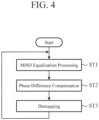
- FIG. 4 is a flowchart illustrating the optical space communication reception method according to second embodiment, and illustrates each processing of the MISO equalization processing unit 473, the phase difference compensating unit 474, and the demapping unit 475 in the receivers 47a to 47d.
- the MISO equalization processing unit 473 performs MISO processing and equalization processing on the plurality of digital signals from the ADC 472 (step ST1).
- the phase difference compensating unit 474 compensates for the phase difference of the signal subjected to the MISO processing and the equalization processing by the MISO equalization processing unit 473 (step ST2).
- the demapping unit 475 performs demapping on the signal whose phase difference has been compensated by the phase difference compensating unit 474 (step ST3).
- the receivers 47a to 47d input signals from the ADC 472 and repeatedly execute the processing in step ST1 to ST3.
- the hardware configuration for achieving the functions of the receivers 47a to 47d is as follows.
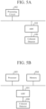
- FIG. 5A is a block diagram illustrating the hardware configuration for implementing the functions of the receivers 47a to 47d
- FIG. 5B is a block diagram illustrating the hardware configuration for executing software for implementing the functions of the receivers 47a to 47d.
- the coherent detector 100 is the coherent detector 471a and the coherent detector 471b illustrated in FIG. 3
- the ADC 101 is the ADC 472 illustrated in FIG. 3 .
- the functions of the MISO equalization processing unit 473, the phase difference compensating unit 474, and the demapping unit 475 included in the receivers 47a to 47d are implemented by a processing circuit (digital signal processing circuit). That is, the receivers 47a to 47d include a processing circuit for executing the processing of Steps ST1 to ST3 illustrated in FIG. 4 .
- the processing circuit may be dedicated hardware or a central processing unit (CPU) that executes a program stored in a memory.
- the processing circuit 102 corresponds to, for example, a single circuit, a composite circuit, a programmed processor, a parallel programmed processor, an application specific integrated circuit (ASIC), a field-programmable gate array (FPGA), or a combination thereof.
- the functions of the MISO equalization processing unit 473, the phase difference compensating unit 474, and the demapping unit 475 included in the receivers 47a to 47d may be implemented by separate processing circuits, or these functions may be collectively implemented by one processing circuit.
- the functions of the MISO equalization processing unit 473, the phase difference compensating unit 474, and the demapping unit 475 included in the receivers 47a to 47d are implemented by software, firmware, or a combination of software and firmware. Note that the software or firmware is described as a program and stored in a memory 104.
- the processor 103 reads out and executes the program stored in the memory 104 to implement the functions of the MISO equalization processing unit 473, the phase difference compensating unit 474 and the demapping unit 475 included in the receivers 47a to 47d.
- the receivers 47a to 47d include the memory 104 that stores a program that, when executed by the processor 103, results in execution of the processing from Step ST1 to Step ST3 illustrated in FIG. 4 .
- These programs cause a computer to execute the procedures or methods performed by the MISO equalization processing unit 473, the phase difference compensating unit 474, and the demapping unit 475.
- the memory 104 may be a computer-readable storage medium storing a program for causing a computer to function as the MISO equalization processing unit 473, the phase difference compensating unit 474, and the demapping unit 475.
- the memory 104 corresponds to, for example, a nonvolatile or volatile semiconductor memory such as a random access memory (RAM), a read only memory (ROM), a flash memory, an erasable programmable read only memory (EPROM), or an electrically-EPROM (EEPROM), a magnetic disk, a flexible disk, an optical disk, a compact disk, a mini disk, or a DVD.
- RAM random access memory
- ROM read only memory
- EPROM erasable programmable read only memory
- EEPROM electrically-EPROM
- the functions of the MISO equalization processing unit 473, the phase difference compensating unit 474, and the demapping unit 475 included in the receivers 47a to 47d may be implemented by dedicated hardware, and the remaining may be implemented by software or firmware.
- the functions of the MISO equalization processing unit 473 and the phase difference compensating unit 474 are implemented by the processing circuit 102 that is dedicated hardware, and the functions of the demapping unit 475 are implemented by the processor 103 reading out and executing a program stored in the memory 104.
- the processing circuit can implement the above functions by hardware, software, firmware, or a combination thereof.
- the optical space communication transmitting and receiving terminal 4 includes the demultiplexers 46a and 46b that demultiplex the multiplexed optical signals for the respective wavelengths, and the receivers 47a to 47d that are provided to each of multiplexed wavelengths and receive the optical signals demultiplexed by the demultiplexers 46a and 46b.
- the optical antennas 41a and 41b collect the light propagated through the space, and the optical amplifiers 45a and 45b amplify the light collected by the optical antennas 41a and 41b.
- the demultiplexers 46a and 46b demultiplex the light amplified by the optical amplifiers 45a and 45b into optical signals for each wavelength multiplexed with the light, and the receivers 47a to 47d demodulate and decode the optical signals demultiplexed by the demultiplexers 46a and 46b. Since the optical space communication transmitting and receiving terminal 4 has the same configuration as the optical space communication transmitting terminal 2, the same effects as those of the first embodiment can be obtained. Moreover, the noise superimposed on each signal collected by the optical antennas 41a and 41b is mainly generated from the optical amplifiers 45a and 45b at the preceding stages of the demultiplexers 46a and 46b, and is noise independent from each other. Therefore, the optical space communication transmitting and receiving terminal 4 coherently detects the signals collected by the optical antennas 41a and 41b and performs the MISO processing on the coherently detected signals, thereby improving the SNR of the reception signal and suppressing a decrease in communication capacity.
- FIG. 6 is a block diagram illustrating the configuration of an optical space communication system 1A according to a third embodiment.
- the optical space communication system 1A is, for example, a system that communicates optical signals in which light beams having four different wavelengths ⁇ 1 to ⁇ 4 are wavelength-multiplexed, and communicates optical signals in which light beams having four different wavelengths ⁇ 5 to ⁇ 8 are wavelength-multiplexed, and includes an optical space communication transmitting and receiving terminal 4 and an optical space communication transmitting and receiving terminal 5.
- the optical space communication transmitting and receiving terminal 4 is a first transmitting and receiving terminal that transmits, to the optical spatial communication transmitting and receiving terminal 5, an optical signal obtained by wavelength-multiplexing the light having the wavelengths ⁇ 1 to ⁇ 4, and receives, by the optical space communication transmitting and receiving terminal 5, an optical signal obtained by wavelength-multiplexing the light having the wavelengths ⁇ 5 to ⁇ 8.
- the optical space communication transmitting and receiving terminal 5 is a second transmitting and receiving terminal that transmits, to the optical space communication transmitting and receiving terminal 4, an optical signal obtained by wavelength-multiplexing the light having the wavelengths ⁇ 5 to ⁇ 8, and receives, by the optical space communication transmitting and receiving terminal 4, an optical signal obtained by wavelength-multiplexing the light having the wavelengths ⁇ 1 to ⁇ 4. That is, the optical space communication transmitting and receiving terminal 4 and the optical space communication transmitting and receiving terminal 5 perform bidirectional communication.
- the optical space communication transmitting and receiving terminal 5 includes an optical antenna 51, an optical amplifier 52a, an optical amplifier 52b, a multiplexer 53, a demultiplexer 54, transmitters 55a to 55d, and receivers 56a to 56d.
- the transmitters 55a to 55d are coherent transmitters (Tx ( ⁇ 5) to Tx ( ⁇ 8)) that transmit optical signals having wavelengths ⁇ 5 to ⁇ 8.
- the multiplexer 53 multiplexes the optical signals having the wavelengths ⁇ 5 to ⁇ 8 to generate an optical signal in which the wavelengths ⁇ 5 to ⁇ 8 are wavelength-multiplexed.
- the optical amplifier 52a amplifies the wavelength-multiplexed signal generated by the multiplexer 53.
- the optical antenna 51 transmits the wavelength-multiplexed signal amplified by the optical amplifier 52a to the optical space communication transmitting and receiving terminal 4.
- the optical antenna 51 collects the light transmitted from the optical space communication transmitting and receiving terminal 4 and propagating in the space.
- the optical amplifier 52b amplifies the light collected by the optical antenna 51.
- the demultiplexer 54 demultiplexes the optical signal for each wavelength wavelength-multiplexed with the light amplified by the optical amplifier 52b.
- the receivers 56a to 56d are coherent receivers (Rx ( ⁇ 1) to Rx ( ⁇ 4)) that receive each of optical signals demultiplexed into the wavelengths ⁇ 1 to ⁇ 4 by the demultiplexer 54.
- An angle formed by two straight lines connecting the opening center of the optical antenna 41a and the opening center of the optical antenna 41b included in the optical space communication transmitting and receiving terminal 4 with the opening center of the optical antenna 51 of the optical space communication transmitting and receiving terminal 5 as an apex falls within an allowable angle error range with respect to incident light in the optical space communication transmitting and receiving terminal 5.
- the light transmitted by the optical antenna 41a and the optical antenna 41b is incident on the optical antenna 51 at an incident angle within an allowable angle error range, and is received in the similar manner as the wavelength multiplexed signal transmitted by one optical antenna.
- an angle formed by each of two straight lines connecting the opening center of the optical antenna 41a and the opening center of the optical antenna 41b with the opening center of the optical antenna 51 as an apex is an extremely small angle. Therefore, the angle falls within the allowable angle error range with respect to the incident light in the optical space communication transmitting and receiving terminal 5.
- the optical space communication system 1A includes the optical space communication transmitting and receiving terminal 4 and the optical space communication transmitting and receiving terminal 5.
- An angle formed by two straight lines connecting the opening center of the optical antenna 41a and the opening center of the optical antenna 41b included in the optical space communication transmitting and receiving terminal 4 with the opening center of the optical antenna 51 of the optical space communication transmitting and receiving terminal 5 as an apex falls within an allowable angle error range with respect to incident light in the optical space communication transmitting and receiving terminal 5.
- the optical space communication transmitting and receiving terminal 5 can receive the light transmitted by the optical antenna 41a and the optical antenna 41b in the similar manner as the light transmitted by one optical antenna.
- optical space communication terminal can be utilized for, for example, optical space communication with an artificial satellite.
- 1, 1A optical space communication system
- 2 optical space communication transmitting terminal
- 3 optical space communication receiving terminal
- 4, 5 optical space communication transmitting and receiving terminal
Landscapes
- Engineering & Computer Science (AREA)
- Computer Networks & Wireless Communication (AREA)
- Signal Processing (AREA)
- Physics & Mathematics (AREA)
- Electromagnetism (AREA)
- Astronomy & Astrophysics (AREA)
- General Physics & Mathematics (AREA)
- Optical Communication System (AREA)
Abstract
Description
- The present disclosure relates to an optical space communication terminal, a receiver, an optical space communication system, and an optical space communication reception method.
- Optical space communication uses a light having a shorter wavelength as a carrier than that in microwave wireless communication, and can efficiently transmit light with suppressed beam spread. Therefore, application of the optical space communication to feeder link of next-generation geostationary satellites has been studied (See, for example, Non-Patent
Literature 1. - Non-Patent Literature 1: P. Shubert et al., "System Design of a High Capacity Optical Relay Network", Proc. ICSOS 2019, S3.3.
- As described in Non-Patent
Literature 1, in order to achieve Tbps class feeder link in the optical space communication, optical power of more than 100 W is required. However, it is difficult to realize a high-output optical amplifier of a class higher than 100 W, and in a conventional optical space communication technology, there is a problem that a communication capacity decreases due to insufficient output of an optical amplifier. For example, when the output of the optical amplifier is insufficient, the transmission power of the optical space communication transmitting terminal is insufficient, and accordingly, the optical power reaching the optical space communication receiving terminal is also insufficient, and the signal-to-noise ratio (SNR) of the signal demodulated from the reception signal decreases, so that the communication capacity decreases. - The present disclosure solves the above problems, and an object thereof is to obtain an optical space communication terminal, a receiver, an optical space communication system, and an optical space communication reception method capable of suppressing a decrease in communication capacity due to an insufficient output of an optical amplifier in optical space communication.
- An optical space communication terminal according to the present disclosure includes: a plurality of transmitters forming a plurality of groups and respectively transmit optical signals of wavelengths different from each other; a plurality of multiplexers each provided to each of the plurality of groups to output an optical signal obtained by wavelength-multiplexing the optical signals transmitted from transmitters belonging to said each of the plurality of groups; a plurality of optical amplifiers each provided to each of the plurality of groups to amplify the optical signal obtained by wavelength-multiplexing the optical signals; and a plurality of optical antennas each provided to each of the plurality of groups to transmit the amplified optical signal to a space, wherein optical antennas, among the plurality of optical antennas, belonging to a same group among the plurality of groups transmit the amplified optical signal in a same direction.
- According to the present disclosure, a plurality of wavelengths to be wavelength-multiplexed are divided into groups, optical signals of different wavelengths are multiplexed for each of the groups, the wavelength-multiplexed optical signals are amplified, and the amplified optical signals are transmitted in the same direction for each of the groups. Therefore, transmission power of each wavelength can be increased. As a result, the optical power reaching the reception side also increases, and the SNR of the signal demodulated from the reception signal is improved, so that it is possible to suppress a decrease in the communication capacity due to the insufficient output of the optical amplifier in the optical space communication.
-
-
FIG. 1 is a block diagram illustrating a configuration of an optical space communication system according to a first embodiment. -
FIG. 2 is a block diagram illustrating a configuration of an optical space communication terminal according to a second embodiment. -
FIG. 3 is a block diagram illustrating a configuration of a receiver according to the second embodiment. -
FIG. 4 is a flowchart illustrating an optical space communication reception method according to the second embodiment. -
FIG. 5A is a block diagram illustrating a hardware configuration for implementing functions of a receiver according to the second embodiment, andFIG. 5B is a block diagram illustrating a hardware configuration for executing software for implementing the functions of the receiver according to the second embodiment. -
FIG. 6 is a block diagram illustrating a configuration of an optical space communication system according to a third embodiment. -
FIG. 1 is a block diagram illustrating the configuration of an opticalspace communication system 1 according to a first embodiment. InFIG. 1 , the opticalspace communication system 1 is, for example, a system that communicates optical signals in which light beams having four different wavelengths λ1 to λ4 are wavelength-multiplexed, and includes an optical spacecommunication transmitting terminal 2 and an optical space communication receiving terminal 3. - The optical space
communication transmitting terminal 2 transmits an optical signal obtained by wavelength-multiplexing light having wavelengths λ1 to λ4. The optical signal is a signal obtained by mapping a transmission signal to the optical space communication receiving terminal 3 to a signal point for an optical signal. The optical space communication receiving terminal 3 receives an optical signal transmitted by the optical spacecommunication transmitting terminal 2. The transmission signal is demapped from the signal point of the optical signal received by the optical space communication receiving terminal 3. - The components of the optical space
communication transmitting terminal 2 are divided into a group (1) and a group (2). Anoptical antenna 21a, anoptical amplifier 22a, amultiplexer 23a, atransmitter 24a, and atransmitter 24b belong to the group (1). Anoptical antenna 21b, anoptical amplifier 22b, amultiplexer 23b, atransmitter 24c, and atransmitter 24d belong to the group (2). The group (1) transmits an optical signal obtained by wavelength-multiplexing adjacent wavelength λ1 and wavelength λ2 among the four wavelengths λ1 to λ4, and the group (2) transmits an optical signal obtained by wavelength-multiplexing adjacent wavelength λ3 and wavelength λ4. - As the plurality of wavelengths to be wavelength-multiplexed, those having no overlap in the spectral band of the optical signal at the interval of adjacent wavelengths are used. For example, in the group (1), there is no overlap between the spectral band of the optical signal having the wavelength λ1 and the spectral band of the optical signal having the wavelength λ2, and in the group (2), there is no overlap between the spectral band of the optical signal having the wavelength λ3 and the spectral band of the optical signal having the wavelength λ4. Moreover, there is no overlap between the spectral band of the optical signal of any wavelength in the group (1) and the spectral band of the optical signal of any wavelength in the group (2). As a result, interference between optical signals having close wavelengths is suppressed.
- In the group (1), the
transmitter 24a is a coherent transmitter (Tx (λ1)) that transmits an optical signal having a wavelength λ1, and thetransmitter 24b is a coherent transmitter (Tx (λ2)) that transmits an optical signal having a wavelength λ2. Themultiplexer 23a generates an optical signal in which the wavelengths λ1 and λ2 are wavelength-multiplexed by multiplexing the optical signal having the wavelength λ1 and the optical signal having the wavelength λ2. Theoptical amplifier 22a amplifies the wavelength multiplexed signal generated by themultiplexer 23a. - In the group (2), the
transmitter 24c is a coherent transmitter (Tx (λ3)) that transmits the optical signal having the wavelength λ3, and thetransmitter 24d is a coherent transmitter (Tx (λ4)) that transmits the optical signal having the wavelength λ4. Themultiplexer 23b generates an optical signal in which the wavelengths λ3 and λ4 are wavelength-multiplexed by multiplexing the optical signal having the wavelength λ3 and the optical signal having the wavelength λ4. Theoptical amplifier 22b amplifies the wavelength multiplexed signal generated by themultiplexer 23b. - The
optical antenna 21a belonging to the group (1) transmits the optical signal, in which the wavelength λ1 and the wavelength λ2 are wavelength-multiplexed and which is amplified by theoptical amplifier 22a, to the optical space communication receiving terminal 3. Similarly, theoptical antenna 21b belonging to the group (2) transmits the optical signal, in which the wavelength λ3 and the wavelength λ4 are wavelength-multiplexed and which is amplified by theoptical amplifier 22b, to the optical space communication receiving terminal 3. That is, theoptical antenna 21a and theoptical antenna 21b transmit optical signals in the same direction in which a common transmission target is present. - Since there is a limit to the output power of each of the
optical amplifier 22a and theoptical amplifier 22b, the optical spacecommunication transmitting terminal 2 divides a plurality of wavelengths to be wavelength-multiplexed into N (N is an integer of 2 or more) groups, multiplexes optical signals of different wavelengths for each group, amplifies the wavelength-multiplexed optical signals, and transmits the amplified optical signals in the same direction for each group. As a result, the transmission power of the signal of each wavelength becomes N times, and the signal of the optical power of N times per each wavelength is received with respect to the optical space communication receiving terminal 3. Therefore, in the optical spacecommunication transmitting terminal 2, the SNR is improved by about N times, and a communication capacity of about N times can be achieved. - Since the optical signal output from the
optical antenna 21a and the optical signal output from theoptical antenna 21b have different wavelengths, interference is reduced. As a result, a wavelength multiplexed optical signal is transmitted to the optical space communication receiving terminal 3, similarly to the wavelength multiplexed signal transmitted by one optical antenna is transmitted. - In the optical space
communication transmitting terminal 2, the output power of each optical amplifier can be lowered without changing the communication capacity as compared with the case where the optical signals having the wavelengths λ1 to λ4 are multiplexed to be one wavelength multiplexed signal, amplified by one optical amplifier, and then transmitted by one optical antenna. That is, although the transmission power of the signal of each wavelength increases, the transmission power of each optical antenna decreases, so that the optical spacecommunication transmitting terminal 2 is effective from the viewpoint of eye safety. - In the optical space
communication transmitting terminal 2, transmission systems of optical signals having close wavelengths among a plurality of wavelengths to be wavelength-multiplexed are grouped into the same group. As a result, the wavelength range supported by the optical amplifiers and the optical antennas belonging to the same group is narrower than those in a case where all optical signals obtained by wavelength multiplexing of a plurality of wavelengths are collectively amplified and transmitted, so that the wavelength dependency of the gain in the optical amplifiers is reduced. - In an optical amplifier having a filter therein for keeping the gain constant, the loss of the filter is reduced. Since the wavelength range supported by the optical antenna for each group is narrowed by dividing the optical signals of the plurality of wavelengths into groups, the optical system having a simpler configuration is allowed for the optical space
communication transmitting terminal 2. For example, the number of lenses for suppressing chromatic aberration can be reduced, and the number of layers of a dielectric multilayer film for preventing reflection can be reduced. - The optical space communication receiving terminal 3 includes an
optical antenna 31, anoptical amplifier 32, ademultiplexer 33, areceiver 34a, areceiver 34b, areceiver 34c, and areceiver 34d. Theoptical antenna 31 collects the light transmitted from the optical spacecommunication transmitting terminal 2 and propagating in the space. Theoptical amplifier 32 amplifies the light collected by theoptical antenna 31. Thedemultiplexer 33 demultiplexes the optical signal wavelength-multiplexed with the light amplified by theoptical amplifier 32 for each wavelength. - The
receiver 34a is a coherent receiver (Rx (λ1)) that receives an optical signal having a wavelength λ1 among the optical signals demultiplexed for each wavelength by thedemultiplexer 33. Thereceiver 34b is a coherent receiver (Rx (λ2)) that receives an optical signal having a wavelength λ2 among the optical signals demultiplexed for each wavelength by thedemultiplexer 33. Thereceiver 34c is a coherent receiver (Rx (λ3)) that receives an optical signal having a wavelength λ3 among the optical signals demultiplexed for each wavelength by thedemultiplexer 33. Thereceiver 34d is a coherent receiver (Rx (λ4)) that receives an optical signal having a wavelength λ4 among the optical signals demultiplexed for each wavelength by thedemultiplexer 33. - The angle formed by two straight lines connecting the opening center of the
optical antenna 21a and the opening center of theoptical antenna 21b included in the optical spacecommunication transmitting terminal 2 with the opening center of theoptical antenna 31 of the optical space communication receiving terminal 3 as an apex falls within an allowable angle error range with respect to incident light in the optical space communication receiving terminal 3. As a result, the light transmitted by theoptical antenna 21a and theoptical antenna 21b included in the optical spacecommunication transmitting terminal 2 is incident on theoptical antenna 31 included in the optical space communication receiving terminal 3 at an incident angle within the allowable angle error range, and is received in the similar manner as the wavelength multiplex signal transmitted by one optical antenna. - For example, when the communication distance between the optical space
communication transmitting terminal 2 and the optical space communication receiving terminal 3 is long, the angle formed by two straight lines connecting the opening center of theoptical antenna 21a and the opening center of theoptical antenna 21b with the opening center of theoptical antenna 31 as an apex is an extremely small angle. Therefore, the angle falls, as a result, within the allowable angle error range with respect to the incident light in the optical space communication receiving terminal 3. - In the above description, the case where the optical space
communication transmitting terminal 2 performs wavelength multiplexing of optical signals of four wavelengths has been described. However, signals of two wavelengths different from each other may be wavelength-multiplexed, or three or more wavelengths may be wavelength-multiplexed. Moreover, in the above description, the components of the optical spacecommunication transmitting terminal 2 are divided into the group (1) and the group (2), but the components of the optical spacecommunication transmitting terminal 2 may be divided into three or more groups. - Furthermore, in the above description, the case where two different wavelengths of two signals are wavelength-multiplexed for each group in the optical space
communication transmitting terminal 2 has been described, but the number of wavelengths to be wavelength-multiplexed in each group may not be the same. For example, in a case where the number of wavelengths to be wavelength-multiplexed is five, three different wavelengths of three signals may be wavelength-multiplexed in the group (1), and two different wavelengths of two signals may be wavelength-multiplexed in the group (2). - As described above, the optical space
communication transmitting terminal 2 according to the first embodiment divides a plurality of wavelengths to be wavelength-multiplexed into groups, multiplexes optical signals having different wavelengths for each group, amplifies the wavelength-multiplexed optical signals, and transmits the amplified optical signals in the same direction for each group. As a result, the optical spacecommunication transmitting terminal 2 can increase the transmission power of each wavelength, and accordingly, the optical power reaching the reception side also increases, and the SNR of the signal demodulated from the reception signal is improved, so that it is possible to suppress a decrease in the communication capacity due to the insufficient output of the optical amplifier in the optical space communication. - In the optical
space communication system 1 according to the first embodiment, an angle formed by two straight lines connecting the opening center of theoptical antenna 21a and the opening center of theoptical antenna 21b included in the optical spacecommunication transmitting terminal 2 with the opening center of theoptical antenna 31 of the optical space communication receiving terminal 3 as an apex falls within an allowable angle error range with respect to the incident light in the optical space communication reception terminal 3. As a result, the optical space communication receiving terminal 3 can receive the light transmitted by theoptical antenna 21a and theoptical antenna 21b in the similar manner as the light transmitted by one optical antenna. -
FIG. 2 is a block diagram illustrating the configuration of an optical space communication transmitting and receivingterminal 4 which is an optical space communication terminal according to a second embodiment. InFIG. 2 , the optical space communication transmitting and receivingterminal 4 is an optical space communication terminal that transmits an optical signal obtained by wavelength-multiplexing light having wavelengths λ1 to λ4 and receives an optical signal obtained by wavelength-multiplexing light having wavelengths λ5 to λ8, and transmits and receives the optical signal using anoptical antenna 41a and anoptical antenna 41b. - Moreover, the optical space communication transmitting and receiving
terminal 4 includes anoptical amplifier 42a, an optical amplifier 42b, amultiplexer 43a, amultiplexer 43b, atransmitter 44a, atransmitter 44b, atransmitter 44c, and atransmitter 44d as components that transmit optical signals, and includes anoptical amplifier 45a, anoptical amplifier 45b, ademultiplexer 46a, ademultiplexer 46b, areceiver 47a, areceiver 47b, areceiver 47c, and areceiver 47d as components that receive optical signals. - Components that transmit optical signals in the optical space communication transmitting and receiving
terminal 4 are divided into a group (1) and a group (2) as in the first embodiment. Theoptical antenna 41a, theoptical amplifier 42a, themultiplexer 43a, thetransmitter 44a, and thetransmitter 44b belong to the group (1). Theoptical antenna 41b, the optical amplifier 42b, themultiplexer 43b, thetransmitter 44c, and thetransmitter 44d belong to the group (2). The group (1) transmits an optical signal obtained by wavelength-multiplexing adjacent wavelengths λ1 and λ2 among the four wavelengths λ1 to λ4. The group (2) transmits an optical signal obtained by wavelength-multiplexing adjacent wavelengths λ3 and λ4. - As the plurality of wavelengths to be wavelength-multiplexed, those having no overlap in the spectral band of the optical signal between adjacent wavelengths are used as in the first embodiment. For example, in the group (1), there is no overlap between the spectral band of the optical signal having the wavelength λ1 and the spectral band of the optical signal having the wavelength λ2, and in the group (2), there is no overlap between the spectral band of the optical signal having the wavelength λ3 and the spectral band of the optical signal having the wavelength λ4. Moreover, there is no overlap between the spectral band of the optical signal of any wavelength in the group (1) and the spectral band of the optical signal of any wavelength in the group (2). As a result, interference between optical signals having close wavelengths is suppressed.
- In the group (1), the
transmitter 44a is a coherent transmitter (Tx (λ1)) that transmits an optical signal having a wavelength λ1, and thetransmitter 44b is a coherent transmitter (Tx (λ2)) that transmits an optical signal having a wavelength λ2. Themultiplexer 43a multiplexes the optical signal having the wavelength λ1 and the optical signal having the wavelength λ2 to generate an optical signal in which the wavelengths λ1 and λ2 are wavelength-multiplexed. Theoptical amplifier 42a amplifies the wavelength multiplexed signal generated by themultiplexer 43a. - In the group (2), the
transmitter 44c is a coherent transmitter (Tx (λ3)) that transmits the optical signal having the wavelength λ3, and thetransmitter 44d is a coherent transmitter (Tx (λ4)) that transmits the optical signal having the wavelength λ4. Themultiplexer 43b multiplexes the optical signal having the wavelength λ3 and the optical signal having the wavelength λ4 to generate an optical signal in which the wavelengths λ3 and λ4 are wavelength-multiplexed. The optical amplifier 42b amplifies the wavelength multiplexed signal generated by themultiplexer 43b. - The
optical antenna 41a belonging to the group (1) transmits an optical signal, in which the wavelength λ1 and the wavelength λ2 amplified by theoptical amplifier 42a are wavelength-multiplexed. Similarly, theoptical antenna 41b belonging to the group (2) transmits an optical signal in which the wavelength λ3 and the wavelength λ4 amplified by the optical amplifier 42b are wavelength-multiplexed. That is, theoptical antenna 41a and theoptical antenna 41b transmit optical signals in the same direction in which a common transmission target is present. - Since there is a limit to the output power of each of the
optical amplifiers 42a and the optical amplifier 42b, the optical space communication transmitting and receivingterminal 4 divides a plurality of wavelengths to be wavelength-multiplexed into N (N is an integer of 2 or more) groups, multiplexes optical signals of different wavelengths for each group, amplifies the wavelength-multiplexed optical signals, and transmits the amplified optical signals group in the same direction for each. As a result, the transmission power of the signal of each wavelength becomes N times, and the signal of the optical power of N times per wavelength is received on the reception side. Therefore, in the optical space communication transmitting and receivingterminal 4, the SNR is improved by about N times, and a communication capacity of about N times can be achieved. - In a reception system of the optical signals of the optical space communication transmitting and receiving
terminal 4, theoptical antenna 41a and theoptical antenna 41b collect the light propagating in the space. For example, in a case where the communication distance to the optical space communication transmitting and receivingterminal 4 is long, the light that has propagated through the space and reached the optical space communication transmitting and receivingterminal 4 is sufficiently spread, and thus enters the plurality of optical antennas. - The
optical amplifier 45a amplifies the light collected by theoptical antenna 41b, and theoptical amplifier 45b amplifies the light collected by theoptical antenna 41a. Thedemultiplexer 46a demultiplexes the optical signal for each wavelength wavelength-multiplexed with the light amplified by theoptical amplifier 45a, and thedemultiplexer 46b demultiplexes the optical signal for each wavelength wavelength-multiplexed with the light amplified by theoptical amplifier 45b. - The
receiver 47a is a coherent receiver (Rx (λ5)) that receives the optical signal having the wavelength λ5 among the optical signals demultiplexed for each wavelength by thedemultiplexer 46a and receives the optical signal having the wavelength λ5 among the optical signals demultiplexed for each wavelength by thedemultiplexer 46b. Thereceiver 47b is a coherent receiver (Rx (λ6)) that receives the optical signal having the wavelength λ6 among the optical signals demultiplexed for each wavelength by thedemultiplexer 46a and receives the optical signal having the wavelength λ6 among the optical signals demultiplexed for each wavelength by thedemultiplexer 46b. - The
receiver 47c is a coherent receiver (Rx (λ7)) that receives the optical signal having the wavelength λ7 among the optical signals demultiplexed for each wavelength by thedemultiplexer 46a and receives the optical signal having the wavelength λ7 among the optical signals demultiplexed for each wavelength by thedemultiplexer 46b. Thereceiver 47d is a coherent receiver (Rx (λ8)) that receives the optical signal having the wavelength λ8 among the optical signals demultiplexed for each wavelength by thedemultiplexer 46a and receives the optical signal having the wavelength λ8 among the optical signals demultiplexed for each wavelength by thedemultiplexer 46b. -
FIG. 3 is a block diagram illustrating the configuration of thereceivers 47a to 47d. InFIG. 3 , thereceivers 47a to 47d are coherent receivers that receive the optical signals demultiplexed by thedemultiplexer 46a and thedemultiplexer 46b. Thereceivers 47a to 47d each include acoherent detector 471a, acoherent detector 471b, an ADC 472, a MISOequalization processing unit 473, a phasedifference compensating unit 474, and ademapping unit 475. Note that the MISOequalization processing unit 473, the phasedifference compensating unit 474, and thedemapping unit 475 are functional components included in a digital signal processing circuit connected to the ADC 472. - The
coherent detector 471a and thecoherent detector 471b are detectors that convert an optical signal having a wavelength demultiplexed by thedemultiplexer 46a and thedemultiplexer 46b into an electrical signal by interfering with local light (laser light) output from a local light emitting source. For example, in thereceiver 47a, thecoherent detector 471a causes the optical signal having the wavelength λ5 demultiplexed by thedemultiplexer 46a to interfere with the local light output from the local light emitting source to convert the optical signal into an electrical signal. Thecoherent detector 471b causes the optical signal having the wavelength λ5 demultiplexed by thedemultiplexer 46b to interfere with the local light output from the local light emitting source to convert the optical signal into an electrical signal. - The ADC 472 is an AD converter that converts an analog electrical signal corresponding to an optical signal of a wavelength demultiplexed from the reception optical signal into a digital signal using each electrical signal coherently detected by the
coherent detector 471a and thecoherent detector 471b. For example, in thereceiver 47a, the ADC 472 converts an analog electrical signal corresponding to the optical signal having the wavelength λ5 into a digital signal using the electrical signal of the optical signal having the wavelength λ5 detected by thecoherent detector 471a and the electrical signal of the optical signal having the wavelength λ5 detected by thecoherent detector 471b. - The MISO
equalization processing unit 473 performs multiple input single output processing (MISO processing) and equalization processing on the plurality of digital signals converted from the analog electrical signal by the ADC 472. For example, in a case where the MISOequalization processing unit 473 is achieved by an FIR filter, the filter coefficient is adaptively set so that the output of the MISOequalization processing unit 473 approaches the assumed signal point distribution. For the setting of the filter coefficient, a least mean square (LMS) algorithm based on a known signal pattern inserted in advance into a part of the signal may be used, or a method that does not require a known signal pattern, such as a constant envelope reference algorithm or an LMS algorithm based on tentative determination, may be used. - The phase
difference compensating unit 474 compensates for the phase difference of the signal subjected to the MISO processing and the equalization processing by the MISOequalization processing unit 473. For example, the phasedifference compensating unit 474 compensates the frequency difference and the phase difference between the transmission signal output from thetransmitters 44a to 44d and the local light by carrier wave estimation for the signal subjected to the MISO processing and the equalization processing. A series of processes including MISO processing, equalization processing, and phase compensation is demodulation of an optical signal. - The
demapping unit 475 decodes the signal whose phase difference has been compensated by the phasedifference compensating unit 474. For example, for a signal subjected to the MISO processing and the equalization processing, a bit sequence is output as a reception signal in correspondence with mapping of the bit sequence and the signal in the transmission system. The process of converting the demodulated signal point into bit data is decoding of an optical signal. - Note that the
coherent detector 471a, thecoherent detector 471b, and the ADC 472 may be not included in thereceivers 47a to 47d, but may be included in the terminal. In this case, thereceivers 47a to 47d include only a digital signal processing circuit connected to the ADC 472. - An optical space communication reception method according to the second embodiment is as follows.
-
FIG. 4 is a flowchart illustrating the optical space communication reception method according to second embodiment, and illustrates each processing of the MISOequalization processing unit 473, the phasedifference compensating unit 474, and thedemapping unit 475 in thereceivers 47a to 47d. The MISOequalization processing unit 473 performs MISO processing and equalization processing on the plurality of digital signals from the ADC 472 (step ST1). Next, the phasedifference compensating unit 474 compensates for the phase difference of the signal subjected to the MISO processing and the equalization processing by the MISO equalization processing unit 473 (step ST2). Thedemapping unit 475 performs demapping on the signal whose phase difference has been compensated by the phase difference compensating unit 474 (step ST3). Thereceivers 47a to 47d input signals from the ADC 472 and repeatedly execute the processing in step ST1 to ST3. - The hardware configuration for achieving the functions of the
receivers 47a to 47d is as follows. -
FIG. 5A is a block diagram illustrating the hardware configuration for implementing the functions of thereceivers 47a to 47d, andFIG. 5B is a block diagram illustrating the hardware configuration for executing software for implementing the functions of thereceivers 47a to 47d. InFIGS. 5A and 5B , thecoherent detector 100 is thecoherent detector 471a and thecoherent detector 471b illustrated inFIG. 3 , and theADC 101 is the ADC 472 illustrated inFIG. 3 . - The functions of the MISO
equalization processing unit 473, the phasedifference compensating unit 474, and thedemapping unit 475 included in thereceivers 47a to 47d are implemented by a processing circuit (digital signal processing circuit). That is, thereceivers 47a to 47d include a processing circuit for executing the processing of Steps ST1 to ST3 illustrated inFIG. 4 . The processing circuit may be dedicated hardware or a central processing unit (CPU) that executes a program stored in a memory. - In a case where the processing circuit is the
processing circuit 102 of dedicated hardware illustrated inFIG. 5A , theprocessing circuit 102 corresponds to, for example, a single circuit, a composite circuit, a programmed processor, a parallel programmed processor, an application specific integrated circuit (ASIC), a field-programmable gate array (FPGA), or a combination thereof. The functions of the MISOequalization processing unit 473, the phasedifference compensating unit 474, and thedemapping unit 475 included in thereceivers 47a to 47d may be implemented by separate processing circuits, or these functions may be collectively implemented by one processing circuit. - In a case where the processing circuit is the processor 103 illustrated in
FIG. 5B , the functions of the MISOequalization processing unit 473, the phasedifference compensating unit 474, and thedemapping unit 475 included in thereceivers 47a to 47d are implemented by software, firmware, or a combination of software and firmware. Note that the software or firmware is described as a program and stored in a memory 104. - The processor 103 reads out and executes the program stored in the memory 104 to implement the functions of the MISO
equalization processing unit 473, the phasedifference compensating unit 474 and thedemapping unit 475 included in thereceivers 47a to 47d. For example, thereceivers 47a to 47d include the memory 104 that stores a program that, when executed by the processor 103, results in execution of the processing from Step ST1 to Step ST3 illustrated inFIG. 4 . These programs cause a computer to execute the procedures or methods performed by the MISOequalization processing unit 473, the phasedifference compensating unit 474, and thedemapping unit 475. The memory 104 may be a computer-readable storage medium storing a program for causing a computer to function as the MISOequalization processing unit 473, the phasedifference compensating unit 474, and thedemapping unit 475. - The memory 104 corresponds to, for example, a nonvolatile or volatile semiconductor memory such as a random access memory (RAM), a read only memory (ROM), a flash memory, an erasable programmable read only memory (EPROM), or an electrically-EPROM (EEPROM), a magnetic disk, a flexible disk, an optical disk, a compact disk, a mini disk, or a DVD.
- Some part of the functions of the MISO
equalization processing unit 473, the phasedifference compensating unit 474, and thedemapping unit 475 included in thereceivers 47a to 47d may be implemented by dedicated hardware, and the remaining may be implemented by software or firmware. For example, the functions of the MISOequalization processing unit 473 and the phasedifference compensating unit 474 are implemented by theprocessing circuit 102 that is dedicated hardware, and the functions of thedemapping unit 475 are implemented by the processor 103 reading out and executing a program stored in the memory 104. As described above, the processing circuit can implement the above functions by hardware, software, firmware, or a combination thereof. - As described above, in addition to the configuration of the optical space
communication transmitting terminal 2, the optical space communication transmitting and receivingterminal 4 according to the second embodiment includes thedemultiplexers receivers 47a to 47d that are provided to each of multiplexed wavelengths and receive the optical signals demultiplexed by thedemultiplexers optical antennas optical amplifiers optical antennas demultiplexers optical amplifiers receivers 47a to 47d demodulate and decode the optical signals demultiplexed by thedemultiplexers terminal 4 has the same configuration as the optical spacecommunication transmitting terminal 2, the same effects as those of the first embodiment can be obtained. Moreover, the noise superimposed on each signal collected by theoptical antennas optical amplifiers demultiplexers terminal 4 coherently detects the signals collected by theoptical antennas -
FIG. 6 is a block diagram illustrating the configuration of an opticalspace communication system 1A according to a third embodiment. InFIG. 6 , the opticalspace communication system 1A is, for example, a system that communicates optical signals in which light beams having four different wavelengths λ1 to λ4 are wavelength-multiplexed, and communicates optical signals in which light beams having four different wavelengths λ5 to λ8 are wavelength-multiplexed, and includes an optical space communication transmitting and receivingterminal 4 and an optical space communication transmitting and receiving terminal 5. - The optical space communication transmitting and receiving
terminal 4 is a first transmitting and receiving terminal that transmits, to the optical spatial communication transmitting and receiving terminal 5, an optical signal obtained by wavelength-multiplexing the light having the wavelengths λ1 to λ4, and receives, by the optical space communication transmitting and receiving terminal 5, an optical signal obtained by wavelength-multiplexing the light having the wavelengths λ5 to λ8. The optical space communication transmitting and receiving terminal 5 is a second transmitting and receiving terminal that transmits, to the optical space communication transmitting and receivingterminal 4, an optical signal obtained by wavelength-multiplexing the light having the wavelengths λ5 to λ8, and receives, by the optical space communication transmitting and receivingterminal 4, an optical signal obtained by wavelength-multiplexing the light having the wavelengths λ1 to λ4. That is, the optical space communication transmitting and receivingterminal 4 and the optical space communication transmitting and receiving terminal 5 perform bidirectional communication. - As illustrated in
FIG. 6 , the optical space communication transmitting and receiving terminal 5 includes anoptical antenna 51, anoptical amplifier 52a, an optical amplifier 52b, amultiplexer 53, ademultiplexer 54,transmitters 55a to 55d, andreceivers 56a to 56d. Thetransmitters 55a to 55d are coherent transmitters (Tx (λ5) to Tx (λ8)) that transmit optical signals having wavelengths λ5 to λ8. Themultiplexer 53 multiplexes the optical signals having the wavelengths λ5 to λ8 to generate an optical signal in which the wavelengths λ5 to λ8 are wavelength-multiplexed. Theoptical amplifier 52a amplifies the wavelength-multiplexed signal generated by themultiplexer 53. Theoptical antenna 51 transmits the wavelength-multiplexed signal amplified by theoptical amplifier 52a to the optical space communication transmitting and receivingterminal 4. - The
optical antenna 51 collects the light transmitted from the optical space communication transmitting and receivingterminal 4 and propagating in the space. The optical amplifier 52b amplifies the light collected by theoptical antenna 51. Thedemultiplexer 54 demultiplexes the optical signal for each wavelength wavelength-multiplexed with the light amplified by the optical amplifier 52b. Thereceivers 56a to 56d are coherent receivers (Rx (λ1) to Rx (λ4)) that receive each of optical signals demultiplexed into the wavelengths λ1 to λ4 by thedemultiplexer 54. - An angle formed by two straight lines connecting the opening center of the
optical antenna 41a and the opening center of theoptical antenna 41b included in the optical space communication transmitting and receiving terminal 4 with the opening center of theoptical antenna 51 of the optical space communication transmitting and receiving terminal 5 as an apex falls within an allowable angle error range with respect to incident light in the optical space communication transmitting and receiving terminal 5. As a result, the light transmitted by theoptical antenna 41a and theoptical antenna 41b is incident on theoptical antenna 51 at an incident angle within an allowable angle error range, and is received in the similar manner as the wavelength multiplexed signal transmitted by one optical antenna. - For example, when the communication distance between the optical space communication transmitting and receiving
terminal 4 and the optical space communication receiving/transmitting terminal 5 is long, an angle formed by each of two straight lines connecting the opening center of theoptical antenna 41a and the opening center of theoptical antenna 41b with the opening center of theoptical antenna 51 as an apex is an extremely small angle. Therefore, the angle falls within the allowable angle error range with respect to the incident light in the optical space communication transmitting and receiving terminal 5. - As described above, the optical
space communication system 1A according to the third embodiment includes the optical space communication transmitting and receivingterminal 4 and the optical space communication transmitting and receiving terminal 5. An angle formed by two straight lines connecting the opening center of theoptical antenna 41a and the opening center of theoptical antenna 41b included in the optical space communication transmitting and receiving terminal 4 with the opening center of theoptical antenna 51 of the optical space communication transmitting and receiving terminal 5 as an apex falls within an allowable angle error range with respect to incident light in the optical space communication transmitting and receiving terminal 5. As a result, the optical space communication transmitting and receiving terminal 5 can receive the light transmitted by theoptical antenna 41a and theoptical antenna 41b in the similar manner as the light transmitted by one optical antenna. - Note that combinations of the respective embodiments, modifications of any components of the respective embodiments, or omissions of any components in the respective embodiments are possible.
- The optical space communication terminal according to the present disclosure can be utilized for, for example, optical space communication with an artificial satellite.
- 1, 1A: optical space communication system, 2: optical space communication transmitting terminal, 3: optical space communication receiving terminal, 4, 5: optical space communication transmitting and receiving terminal, 21a, 21b, 31, 41a, 41b, 51: optical antenna, 22a, 22b, 32, 42a, 42b, 45a, 45b, 52a, 52b: optical amplifier, 23a, 23b, 43a, 43b, 53: multiplexer, 24a to 24d, 44a to 44d, 55a to 55d: transmitter, 33, 46a, 46b, 54: demultiplexer, 34a to 34d, 47a to 47d, 56a to 56d: receiver, 471a, 471b: coherent detector, 473: MISO equalization processing unit, 474: phase difference compensating unit, 475: demapping unit.,
Claims (6)
- An optical space communication terminal comprising:a plurality of transmitters forming a plurality of groups and respectively transmit optical signals of wavelengths different from each other;a plurality of multiplexers each provided to each of the plurality of groups to output an optical signal obtained by wavelength-multiplexing the optical signals transmitted from transmitters belonging to said each of the plurality of groups;a plurality of optical amplifiers each provided to each of the plurality of groups to amplify the optical signal obtained by wavelength-multiplexing the optical signals; anda plurality of optical antennas each provided to each of the plurality of groups to transmit the amplified optical signal to a space,wherein optical antennas, among the plurality of optical antennas, belonging to a same group among the plurality of groups transmit the amplified optical signal in a same direction.
- The optical space communication terminal according to claim 1, further comprising:a demultiplexer demultiplexing an optical signal to generate a plurality of wavelength-demultiplexed optical signals;a plurality of receivers to receive the plurality of wavelength-demultiplexed optical signals respectively;an optical antenna; andan optical amplifier,wherein the optical antenna collects light propagating through a space,the optical amplifier amplifies the light collected by the optical antenna,the demultiplexer demultiplexes the light amplified by the optical amplifier into the wavelength-demultiplexed optical signals respectively corresponding to the wavelengths different from each other, andthe plurality of receivers demodulate and decode the wavelength-demultiplexed optical signals respectively.
- A receiver that demodulates and decodes the wavelength-demultiplexed optical signals demultiplexed by the demultiplexer included in the optical space communication terminal according to claim 2, the receiver comprising:an MISO equalization processing unit receiving a plurality of digital signals generated by analog-to-digital conversion after the wavelength-demultiplexed optical signals demultiplexed by the demultiplexer are coherently detected, and performing a multiple input single output process to obtain a digital signal and an equalization process on the plurality of digital signals;a phase difference compensating unit compensating for a phase difference of the digital signal obtained by the MISO equalization processing unit; anda demapping unit decoding the digital signal whose phase difference is compensated for by the phase difference compensating unit.
- An optical space communication system comprising:a transmission terminal that is the optical space communication terminal according to claim 1; anda reception terminal to receive an optical signal transmitted by the transmission terminal,wherein an angle formed by two straight lines connecting each of two opening centers of the plurality of optical antennas of the transmission terminal with the opening center of an optical antenna of the reception terminal as an apex falls within an allowable angle error range with respect to incident light of the reception terminal.
- An optical space communication system comprising:a first transmission/reception terminal that is the optical space communication terminal according to claim 2; anda second transmission/reception terminal to transmit and receive an optical signal to and from the first transmission/reception terminal,wherein an angle formed by two straight lines connecting each of two opening centers of the plurality of optical antennas of the first transmission/reception terminal with the opening center of an optical antenna of the second transmission/reception terminal as an apex falls within an allowable angle error range with respect to incident light at the second transmission/reception terminal, andthe first transmission/reception terminal and the second transmission/reception terminal perform bidirectional communication.
- An optical space communication reception method of a receiver that demodulates and decodes the wavelength-demultiplexed optical signals demultiplexed by a demultiplexer included in the optical space communication terminal according to claim 2, the method comprising:a step, performed by a MISO equalization processing unit, of receiving a plurality of digital signals generated by analog-to-digital conversion after the wavelength-demultiplexed optical signals demultiplexed by the demultiplexer are coherently detected, and performing a multiple input single output process to obtain a digital signal and an equalization process on the plurality of input digital signals;a step, performed by a phase difference compensating unit, of compensating for a phase difference of the digital signal obtained by the MISO equalization processing unit; anda step, performed by a demapping unit, of decoding the digital signal whose phase difference is compensated for by the MISO equalization processing unit,wherein a series of processes performed by the MISO equalization processing unit, the phase difference compensating unit, and the demapping unit is repeatedly executed.
Applications Claiming Priority (1)
| Application Number | Priority Date | Filing Date | Title |
|---|---|---|---|
| PCT/JP2020/022394 WO2021245938A1 (en) | 2020-06-05 | 2020-06-05 | Optical space communication terminal, receiver, optical space communication system, and optical space communication reception method |
Publications (2)
| Publication Number | Publication Date |
|---|---|
| EP4145720A1 true EP4145720A1 (en) | 2023-03-08 |
| EP4145720A4 EP4145720A4 (en) | 2023-06-21 |
Family
ID=74673655
Family Applications (1)
| Application Number | Title | Priority Date | Filing Date |
|---|---|---|---|
| EP20939181.2A Pending EP4145720A4 (en) | 2020-06-05 | 2020-06-05 | OPTICAL SPACE COMMUNICATION TERMINAL, RECEIVER, OPTICAL SPACE COMMUNICATION SYSTEM AND OPTICAL SPACE COMMUNICATION RECEPTION METHOD |
Country Status (5)
| Country | Link |
|---|---|
| US (1) | US12088339B2 (en) |
| EP (1) | EP4145720A4 (en) |
| JP (1) | JP6837618B1 (en) |
| CN (1) | CN115699618B (en) |
| WO (1) | WO2021245938A1 (en) |
Families Citing this family (3)
| Publication number | Priority date | Publication date | Assignee | Title |
|---|---|---|---|---|
| GB2628664B (en) * | 2023-03-31 | 2025-08-06 | Toshiba Kk | An optical receiver/transmitter with beamsteering |
| US20240348333A1 (en) * | 2023-04-14 | 2024-10-17 | Ciena Corporation | Method and apparatus for wavelength diversity in free-space optical communications |
| US20250202586A1 (en) * | 2023-12-15 | 2025-06-19 | Ciena Corporation | Wavelength diversity turbulence mitigation method and apparatus for free-space optical communications |
Family Cites Families (15)
| Publication number | Priority date | Publication date | Assignee | Title |
|---|---|---|---|---|
| JP2001091616A (en) * | 1999-09-22 | 2001-04-06 | Mitsubishi Electric Corp | Incident angle estimating apparatus and element antenna array method of incident angle estimating apparatus |
| US7409159B2 (en) * | 2001-06-29 | 2008-08-05 | Hrl Laboratories, Llc | Wireless wavelength division multiplexed system |
| US8462868B2 (en) | 2004-09-23 | 2013-06-11 | The Regents Of The University Of California | Multiple sub-carrier selection diversity architecture and method for wireless OFDM |
| CN101060377A (en) * | 2006-04-17 | 2007-10-24 | 中兴通讯股份有限公司 | A wave coupling and splitting method in a dense wave division multiple transmission system |
| US9130618B2 (en) | 2006-10-26 | 2015-09-08 | Alcatel Lucent | MIMO communication system with variable slot structure |
| JP2009225111A (en) | 2008-03-17 | 2009-10-01 | Fujitsu Ltd | Receiver and reception method |
| CN101667879A (en) * | 2009-10-10 | 2010-03-10 | 中兴通讯股份有限公司 | Method and system capable of realizing multidirectional reconfigurable optical add-drop multiplexing |
| CN104635306A (en) * | 2013-11-08 | 2015-05-20 | 昂纳信息技术(深圳)有限公司 | Multi-wavelength optical transceiver module of single optical fiber coupling |
| JP6173605B2 (en) * | 2014-12-25 | 2017-08-02 | 三菱電機株式会社 | Transmitting apparatus, receiving apparatus, communication apparatus, and satellite communication system |
| DK3611850T3 (en) | 2015-12-31 | 2021-08-02 | Viasat Inc | BROADBAND SATELLITE COMMUNICATION SYSTEM USING OPTICAL FEEDER LINKS |
| CN108476069B (en) * | 2016-04-28 | 2020-03-31 | 华为技术有限公司 | Optical transceiver, wavelength control system and method |
| JP7031608B2 (en) * | 2016-12-13 | 2022-03-08 | 日本電気株式会社 | Optical space communication device and delay adjustment method |
| JP6701466B2 (en) * | 2018-03-01 | 2020-05-27 | 三菱電機株式会社 | Spatial optical communication receiver |
| WO2019207756A1 (en) * | 2018-04-27 | 2019-10-31 | 三菱電機株式会社 | Space optical communication device |
| US10432308B1 (en) * | 2018-08-23 | 2019-10-01 | Space Systems/Loral, Llc | Satellite system using an RF GBBF feeder uplink beam from a gateway to a satellite, and using an optical ISL from the satellite to another satellite |
-
2020
- 2020-06-05 WO PCT/JP2020/022394 patent/WO2021245938A1/en not_active Ceased
- 2020-06-05 JP JP2020554915A patent/JP6837618B1/en active Active
- 2020-06-05 CN CN202080101516.9A patent/CN115699618B/en active Active
- 2020-06-05 EP EP20939181.2A patent/EP4145720A4/en active Pending
-
2022
- 2022-09-27 US US17/953,799 patent/US12088339B2/en active Active
Also Published As
| Publication number | Publication date |
|---|---|
| JPWO2021245938A1 (en) | 2021-12-09 |
| CN115699618B (en) | 2025-11-28 |
| EP4145720A4 (en) | 2023-06-21 |
| JP6837618B1 (en) | 2021-03-03 |
| US20230012584A1 (en) | 2023-01-19 |
| US12088339B2 (en) | 2024-09-10 |
| CN115699618A (en) | 2023-02-03 |
| WO2021245938A1 (en) | 2021-12-09 |
Similar Documents
| Publication | Publication Date | Title |
|---|---|---|
| US12088339B2 (en) | Receiver, optical space communication system, and optical space communication reception method | |
| US10312999B2 (en) | High-capacity communications satellite using passive optical beamforming | |
| EP1813042B1 (en) | Communications method, particularly for a mobile radio network | |
| US10924176B2 (en) | Next generation in-building relay system and method | |
| CN113872695B (en) | Distributed antenna system and communication system | |
| US20150043920A1 (en) | Submarine reconfigurable optical add/drop multiplexer with passive branching unit | |
| US20100232350A1 (en) | Interference removal | |
| US20240405910A1 (en) | Wireless communication method and wireless communication apparatus | |
| US7130542B2 (en) | Modular multiplexing/demultiplexing units in optical transmission systems | |
| WO2009157609A1 (en) | Optical backhaul network for wireless broadband service | |
| US10805033B2 (en) | Optical line terminal, and signal transmission method and device | |
| WO2019155952A1 (en) | Satellite receiver and satellite communication system | |
| CN216290933U (en) | Distributed antenna system and communication system | |
| US10263703B2 (en) | Optical transceiver module for communications in DAS systems | |
| US20200177299A1 (en) | Apparatus and method to reduce the impact of coherent crosstalk in optical networks | |
| JP4727603B2 (en) | Wireless communication apparatus and wireless communication system | |
| EP4712370A1 (en) | Multiplexed communication system, communication device, and control method for same | |
| WO2016203747A1 (en) | Spatial light transmission device and spatial light communication method | |
| US9584247B1 (en) | Flexible ROADM-less optical hub and spoke node architecture for coherent transponders | |
| CN119834893A (en) | Beam forming device, wireless communication device and beam forming method | |
| WO2022029832A1 (en) | Optical transmission system, optical reception device, and optical transmission device | |
| KR20080061511A (en) | Cable Organizers in Multi-antenna Systems |
Legal Events
| Date | Code | Title | Description |
|---|---|---|---|
| STAA | Information on the status of an ep patent application or granted ep patent |
Free format text: STATUS: THE INTERNATIONAL PUBLICATION HAS BEEN MADE |
|
| PUAI | Public reference made under article 153(3) epc to a published international application that has entered the european phase |
Free format text: ORIGINAL CODE: 0009012 |
|
| STAA | Information on the status of an ep patent application or granted ep patent |
Free format text: STATUS: REQUEST FOR EXAMINATION WAS MADE |
|
| 17P | Request for examination filed |
Effective date: 20221123 |
|
| AK | Designated contracting states |
Kind code of ref document: A1 Designated state(s): AL AT BE BG CH CY CZ DE DK EE ES FI FR GB GR HR HU IE IS IT LI LT LU LV MC MK MT NL NO PL PT RO RS SE SI SK SM TR |
|
| A4 | Supplementary search report drawn up and despatched |
Effective date: 20230519 |
|
| RIC1 | Information provided on ipc code assigned before grant |
Ipc: H04J 14/02 20060101ALI20230512BHEP Ipc: H04B 10/118 20130101ALI20230512BHEP Ipc: H04B 10/112 20130101AFI20230512BHEP |
|
| DAV | Request for validation of the european patent (deleted) | ||
| DAX | Request for extension of the european patent (deleted) |