EP4145704B1 - Secure starting of a processing unit - Google Patents
Secure starting of a processing unit Download PDFInfo
- Publication number
- EP4145704B1 EP4145704B1 EP22191050.8A EP22191050A EP4145704B1 EP 4145704 B1 EP4145704 B1 EP 4145704B1 EP 22191050 A EP22191050 A EP 22191050A EP 4145704 B1 EP4145704 B1 EP 4145704B1
- Authority
- EP
- European Patent Office
- Prior art keywords
- value
- til
- data
- counting value
- processing device
- Prior art date
- Legal status (The legal status is an assumption and is not a legal conclusion. Google has not performed a legal analysis and makes no representation as to the accuracy of the status listed.)
- Active
Links
- 238000012545 processing Methods 0.000 title claims description 47
- 230000004224 protection Effects 0.000 claims description 55
- 238000000034 method Methods 0.000 claims description 48
- 230000015654 memory Effects 0.000 claims description 39
- 230000004048 modification Effects 0.000 claims description 9
- 238000012986 modification Methods 0.000 claims description 9
- 230000005540 biological transmission Effects 0.000 claims description 2
- 230000009849 deactivation Effects 0.000 claims description 2
- 238000002955 isolation Methods 0.000 description 36
- 230000008569 process Effects 0.000 description 11
- 238000010586 diagram Methods 0.000 description 5
- 238000009413 insulation Methods 0.000 description 5
- 238000003860 storage Methods 0.000 description 3
- 230000008901 benefit Effects 0.000 description 2
- 230000009850 completed effect Effects 0.000 description 2
- 230000006870 function Effects 0.000 description 2
- 238000004519 manufacturing process Methods 0.000 description 2
- 230000004913 activation Effects 0.000 description 1
- 230000008859 change Effects 0.000 description 1
- 230000000295 complement effect Effects 0.000 description 1
- 239000004020 conductor Substances 0.000 description 1
- 230000007423 decrease Effects 0.000 description 1
- 230000003111 delayed effect Effects 0.000 description 1
- 238000013461 design Methods 0.000 description 1
- 238000009434 installation Methods 0.000 description 1
- 239000000463 material Substances 0.000 description 1
- 230000007246 mechanism Effects 0.000 description 1
- 239000003607 modifier Substances 0.000 description 1
- 230000002633 protecting effect Effects 0.000 description 1
- 239000010453 quartz Substances 0.000 description 1
- 230000002441 reversible effect Effects 0.000 description 1
- VYPSYNLAJGMNEJ-UHFFFAOYSA-N silicon dioxide Inorganic materials O=[Si]=O VYPSYNLAJGMNEJ-UHFFFAOYSA-N 0.000 description 1
- 230000002123 temporal effect Effects 0.000 description 1
- 230000001052 transient effect Effects 0.000 description 1
- 238000011282 treatment Methods 0.000 description 1
- 230000001960 triggered effect Effects 0.000 description 1
- 238000012795 verification Methods 0.000 description 1
Images


Classifications
-
- G—PHYSICS
- G06—COMPUTING; CALCULATING OR COUNTING
- G06F—ELECTRIC DIGITAL DATA PROCESSING
- G06F21/00—Security arrangements for protecting computers, components thereof, programs or data against unauthorised activity
- G06F21/50—Monitoring users, programs or devices to maintain the integrity of platforms, e.g. of processors, firmware or operating systems
- G06F21/57—Certifying or maintaining trusted computer platforms, e.g. secure boots or power-downs, version controls, system software checks, secure updates or assessing vulnerabilities
- G06F21/575—Secure boot
-
- H—ELECTRICITY
- H03—ELECTRONIC CIRCUITRY
- H03K—PULSE TECHNIQUE
- H03K21/00—Details of pulse counters or frequency dividers
- H03K21/38—Starting, stopping or resetting the counter
-
- G—PHYSICS
- G06—COMPUTING; CALCULATING OR COUNTING
- G06F—ELECTRIC DIGITAL DATA PROCESSING
- G06F21/00—Security arrangements for protecting computers, components thereof, programs or data against unauthorised activity
- G06F21/50—Monitoring users, programs or devices to maintain the integrity of platforms, e.g. of processors, firmware or operating systems
- G06F21/57—Certifying or maintaining trusted computer platforms, e.g. secure boots or power-downs, version controls, system software checks, secure updates or assessing vulnerabilities
-
- G—PHYSICS
- G06—COMPUTING; CALCULATING OR COUNTING
- G06F—ELECTRIC DIGITAL DATA PROCESSING
- G06F9/00—Arrangements for program control, e.g. control units
- G06F9/06—Arrangements for program control, e.g. control units using stored programs, i.e. using an internal store of processing equipment to receive or retain programs
- G06F9/30—Arrangements for executing machine instructions, e.g. instruction decode
- G06F9/30003—Arrangements for executing specific machine instructions
Definitions
- the present description concerns the field of methods and devices for the security of electronic circuits, and in particular a device and a method making it possible to carry out secure starting of such a circuit.
- the startup of a processing device is based on the execution of codes such as software and/or firmware codes.
- the startup sequence of a device is a sensitive step in terms of security, because it generally involves the adjustment of parameters related to the security of the device and/or the processing of sensitive data in terms of confidentiality, integrity and authenticity such as encryption keys.
- US 2006/198515 A1 discloses a cryptographic security module with monotonic counter for encrypted data backup controller.
- One embodiment overcomes all or part of the drawbacks of existing solutions.
- the count value is stored in a register of the monotonic counter, the modification of the count value into the first reference value consisting of overwriting the count value by the first reference value in said register.
- the method further comprises the comparison, by the protection circuit, between a current value of a hardware counter clocked by a reference clock with a threshold value in order to determine whether the first duration has been reached.
- the method further comprises deactivation of the protection circuit when the first duration is reached.
- the method further comprises the generation of the count value by the monotonic counter during a first phase of the start-up sequence.
- reading of the first data is prohibited by the access control circuit on the basis of the first reference value.
- the first data comprises first start codes.
- the method further comprises reading, based on the count value, second data stored in the memory.
- the protection circuit is further configured to compare a current value of a hardware counter, clocked by a reference clock, and a first threshold value in order to determine whether the first duration has been reached.
- the protection circuit is configured to be deactivated when the first duration is reached.
- the access control circuit is further configured to allow reading of second data based on the count value.
- the expressions “approximately”, “approximately”, “substantially”, and “of the order of” mean to the nearest 10%, preferably to the nearest 5%.
- FIG. 1A represents, schematically and in block form, an electronic device 100 comprising a processing device 102 according to one embodiment of the present description.
- the electronic device 100 is for example an electronic card such as a microcircuit card, hardware for computer use, or a microprocessor or microcontroller circuit.
- the processing device 102 comprises for example a non-volatile memory 104 (NV MEM), for example a flash memory.
- NV MEM non-volatile memory
- the memory 104 includes, for example, an interface access control 108 (ACCES CONTROL) connected to a monotonous counter 106 (MONOTONIC COUNTER).
- ACCES CONTROL interface access control 108
- MONOTONIC COUNTER monotonous counter
- Monotonic counters are known in the state of the art, an example of such a counter being described in the publication " Virtual Monotony Counters and Count-Limited Objects using a TPM without a Trusted OS" by LFG Sarmenta, M. Van Dijk, CW O'Donnell, J. Rhodes and S. Devadas , and in particular in part 3 of this document.
- This document describes meter implementations implemented in hardware and/or software form.
- the monotonic counter 106 is for example implemented in hardware by a digital circuit, such as a personalized integrated circuit (ASIC, from English "Application Specifies Integrated Circuit").
- the monotonic counter is configured to maintain a count value, accessible on an output of the counter.
- the monotonic counter 106 increases its counting value by one or more units but, following each increment, the operation is not reversible. Indeed, the monotonic counter 106 is configured so that its counting value never decreases. In addition, between two increments, the count value is, for example, protected against any decrease. Only the increment command or a modification command allows the replacement of the current value by a new value greater than the current value.
- the monotonic counter 106 is configured so that no command, apart from resetting the processing device 102, makes it possible to return to the previous counting value.
- the monotonic counter 106 again generates a initial count value.
- an initial count value is for example rewritten in the non-volatile storage element of the monotonic counter 106.
- the count value is by example stored in a register (not shown) of the monotonic counter 106.
- the monotonic counter 106 is, in addition, coupled to a protection circuit 113 (TIL PROTECTION).
- the protection circuit 113 implements a watchdog function. Watchdog functions are known in the state of the art and are used, for example, to ensure that a processing circuit does not remain blocked at a particular step of the processing that it performs. In embodiments of the present disclosure, the watchdog function is employed to reduce the risk that the monotonic counter 106 will become stuck at a given count value.
- the protection circuit 113 is for example connected to a counter 115 (TIMER).
- Counter 115 contains a current value incremented by a clock signal CLK.
- the CLK signal is generated for example by a clock generator (not shown) of the device 102, such as a quartz oscillator.
- the processing device 102 further comprises a generic processor 110 (CPU).
- the generic processor 110 is coupled via a bus 116 to the monotonic counter 106 as well as to a RAM (random access memory) 112 and to the non-volatile memory 104.
- the memory 112 and/or the memory 104 stores, for example, instructions for controlling the processor 110.
- the generic processor 110 is further coupled via the bus 116 to a cryptographic processor 114 (CRYPTO).
- the cryptographic processor 114 receives, via the bus 116, encrypted data and returns the decrypted data and/or receives, via bus 116, unencrypted data and returns the encrypted data.
- the non-volatile memory 104 stores for example several start codes, and/or other data, which are associated with several TIL isolation levels (from the English "temporal isolation level").
- Boot codes are for example software and/or firmware codes.
- the non-volatile memory 104 comprises a first zone 118 in which a first start code and/or first data (CODE0) are stored.
- the memory 104 further comprises a second zone 120, in which a second start code and/or second data (CODE1) are stored, as well as a third zone 122 in which a third start code and/or data are stored.
- third data CODE2).
- the first, second and third start codes and/or data are for example associated with three corresponding TIL isolation levels.
- the non-volatile memory 104 may store only two sets of data, or more than three sets of data, in corresponding areas.
- the first, second and third data include first, second and third start codes.
- the TIL isolation level depends on the count value generated by the monotonic counter 106.
- the TIL value is equal to the count value of the monotonic counter 106, although it would be possible to modify the count value in order to generate the TIL value.
- the reading of the first, second and third codes and/or data and/or the execution of the first, second and third start codes are carried out by steps, each step being associated with a corresponding isolation level.
- the access control circuit 108 of the memory 104 is configured so that the reading of these codes/data is controlled according to the isolation level of the step.
- the first data and/or the first code are for example associated with the isolation level, or TIL value, 0 and the access control circuit 108 is configured so that this data and/or code is only accessible for reading when the current TIL counting value is equal to 0.
- the access control circuit 108 locks the zone 118, the first data and/or the first code are then no longer accessible for reading. Following an increment, the current count value changes for example to 1 and the data and/or the start codes associated with isolation level 1, for example the second start code, are executed.
- the access control circuit 108 is configured to allow the reading of one or more data associated with isolation levels greater than that of the current TIL value. For example, in some embodiments, the lower the insulation level, the greater the level of protection. Isolation level 0 is therefore the level providing the most protection, because the corresponding data can only be read when the count value is equal to 0. Thus, each isolation level corresponds to a level of protection of the content of the memory areas associated with it.
- the access control mechanism implemented by circuit 108 can be implemented in several ways.
- circuit 108 when circuit 108 receives a read request associated with one or more addresses in memory 104, it is configured to compare this/these address(es) to the address ranges associated with areas 118, 120, 122 of memory 104. If it is an address in an area associated with a TIL value lower than the current value, circuit 108 is for example configured to block the read operation.
- circuit 108 is configured to deactivate a reading circuit of any zone 118, 120, 122 of memory 104 associated with a TIL value lower than the current value.
- one or more logic gates such as OR gates or AND gates, are coupled into the output path of each area 118, 120 and 122 of memory 104 and also receive an activation signal generated based on of the TIL value allowing each output path to be selectively deactivated.
- the fact that the counting value cannot be decremented during the operating period of the device 100 allows the protection of the start codes once they have been executed, because the access control circuit 108 prevents the reading of the data and/or or the execution of codes associated with TIL isolation levels lower than the current level.
- one or more of the data and/or startup codes and the associated isolation levels are reserved for parameterization phases of the device 102 or for distinct entities in the chain going from the manufacturer to the final user.
- an intermediary entity between the manufacturer of the processing device 102 and the end user of the electronic device 100 may be required to install data and/or startup codes which are specific to the use of the device 100.
- one or more of the most common data and/or startup codes “low”, for example associated with isolation level 0 are for example reserved for the manufacturer of the processing device 102, and other data and/or startup codes are reserved for the intermediate entity.
- the contents of memory areas 118, 120 and 122 include, in certain embodiments, other data in addition to the startup codes of the processing device 102.
- other sensitive data in terms of confidentiality are stored in association with at least one of the first, second and third codes and/or data.
- this other data includes encryption keys used during the execution of the startup codes associated with them.
- memory zones 204, 206 and 208 store sensitive data associated respectively with the start codes 118, 120 and 122 stored in the non-volatile memory 104. Zones 204, 206 and 208 are for example zones distinct from zones 118, 120 and 122, but remain associated with an isolation level corresponding to that of the start codes to which the data is linked.
- This sensitive data includes for example one or more encryption keys stored in each zone 204, 206 and 208 and each of these zones is contained in the non-volatile memory 104.
- each zone 204, 206 and 208 is a subzone of the corresponding zone 118, 120 and 122.
- TIL value is equal to 0
- the attacker would therefore have access to the data and/or codes associated with the value of TIL 0 at any time during the life of the device 100.
- the protection circuit 113 is for example configured to automatically force the value of TIL to be equal to a given value after a predetermined duration after the start of the start-up sequence.
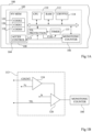
- FIG. 1B schematically represents an embodiment of the protection circuit 113 of the electronic device 100 of the Figure 1A according to one embodiment of the present description.
- the protection circuit 113 includes comparators 124 and 126.
- the comparator 124 receives a signal corresponding to a current value COUNT of the counting value generated by the counter 115 and compares it to a threshold value xT.
- the threshold value xT represents for example a reference duration. This comparison is carried out for example continuously, or at each cycle of the clock, until the COUNT value is greater than or equal to the xT value.
- a comparison by comparator 126 is for example triggered.
- the comparator 126 compares the current TIL value of the monotonic counter 106 with a reference value N.
- the reference value N corresponds to the TIL value which should be current following the reference duration, corresponding to xT, after the start of 'a startup sequence.
- the comparator 126 transmits a signal to the monotonic counter 106 triggering, for example, one or more increments of the monotonic counter 106, in order to that the value of TIL becomes equal to at least the value of reference N.
- the reference value N is then transmitted to the access control circuit 108, which has the consequence of prohibiting access to memory data associated with TIL values lower than N.
- the comparator 126 sends the reference value N to the monotonic counter 106 in order to force the change of the value of TIL towards this reference value N.
- the monotonic counter 106 is for example configured to prohibit the overwriting of its current value by a lower value.
- FIG 2 represents an example of the data and codes accessible during a secure startup of the processing device 102 of the Figure 1A according to one embodiment of the present description.
- the current count value is for example equal to 0.
- an isolation level 0 is associated with a first code (CODE0) as well as with first sensitive data (KEY0).
- the access control circuit 108 is configured, for example, so that this first code and these first data are exclusively accessible when the current count value is equal to 0.
- the control circuit access authorizes for example access to all memory areas 204, 206 and 208, as well as to all areas 118, 120 and 122. Indeed, in certain cases, in order for example to anticipate subsequent steps in the startup process, one or more of the other startup codes CODE1, CODE2 are accessible for reading during step 200.
- the generic processor 110 commands a first increment of the current count value by the monotonic counter 106.
- the first code includes a command requesting the increment of the counter. This command is for example transmitted to a control register (not illustrated) of the monotonic counter 106.
- the current count value of the monotonic counter 106 is for example equal to 1, corresponding to the second step 201 of startup.
- the access control circuit 108 receives the new current count value, and is configured to prevent, on the basis of this count value greater than 0, any access to the first code as well as to the first data which is associated with the level isolation 0. In other words, memory areas 118 and 204 are locked on the basis of any count value strictly greater than 0.
- Insulation level 1 is associated with a second code (CODE1) contained in zone 120 as well as with second data (KEY1) contained in zone 202.
- CODE2 for example example associated with insulation level 2 and contained in zone 122, is accessible for reading on the basis of the current count value equal to 1.
- the generic processor 110 commands a second increment of the current count value by the monotonic counter 106. For example, after this second increment, the current count value of the counter monotone 106 is equal to 2, corresponding to the third step 203 of startup. Isolation level 2 is associated with the third code (CODE2) as well as third data (KEY2).
- the access control circuit 108 receives the new count value, and is configured to prevent, based on this count value greater than 1, any access to the first and second codes as well as to the first and second data which are associated with isolation levels less than or equal to 1.
- the generic processor 110 when the last start code is executed, for example the third start code, commands a third increment of the current count value by the monotonic counter 106.
- the access control circuit 108 then locks all access to the first, second and third start codes as well as the first, second and third data.
- the current count value is not incremented by the monotonic counter 106 and access to the third start code as well as 'to the third data remains authorized by the access control circuit.
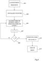
- FIG. 3 is a flowchart representing the operations of a secure startup method of the processing device 102 according to an exemplary embodiment of the present description according to the invention.
- a step 300 (LAUNCH BOOT SEQUENCE AT TIL0 AND START COUNT), the device 102 is reset and a startup sequence begins.
- the monotonic counter 106 then generates a first value of TIL, for example equal to 0.
- the counter 115 is initialized and a current value COUNT of the counter 115 is incremented at each cycle of the clock of the device 102.
- the protection circuit 113 is configured to trigger the increment of the value of TIL to the value M, a duration x1 after the start of the sequence starting.
- this operation 301 includes the configuration of a reference value M and a threshold value x1 in a register. In other embodiments, these values are invariable and stored in a non-volatile manner in a memory of the device 100.
- the protection circuit 113 can also be configured to trigger the increment of the value of TIL to the value N, a duration x2 after the start of the sequence starting.
- this operation 302 includes for example the configuration of a reference value N and a threshold value x2 in a register. In other embodiments, these values are invariable and stored in a non-volatile manner in a memory of the device 100.
- the protection methods on the basis of one or more durations xT are for example implemented in parallel, the Figure 3 illustrating an example of a first method 303 based on duration x1, and a second method 303' based on duration x2.
- the method 303 comprises steps 304 to 306.
- a step 304 (COUNT ⁇ x1?), the comparator 124 of the protection circuit 113 compares the current value COUNT of the counter 115 with the value x1. If the COUNT value is strictly less than the value x1 (branch Y), the process resumes in this same step 304. If the COUNT value is greater than or equal to the value x1 (branch N), the comparator 126 compares the value of TIL current of the monotonic counter 106 with the value M (block 305, TIL ⁇ M). If the current TIL value is greater than or equal to the value M, the process ends in step 307 (END). In the case where the current TIL value is strictly less than the value M, the TIL value is forced to the value M in an operation 306.
- step 307 the process ends in step 307 (END).
- the protection circuit 113 is then only configured to automatically trigger the increment of the TIL value to the value 2.5 microseconds after the start of the startup sequence. In the case where the value of TIL is already equal to 2, the protection circuit 113 is for example deactivated.
- the method 303' comprises operations 304', 305' and 306' similar to operations 304, 305 and 306, except that the threshold value x1 is replaced by the threshold value x2 in operation 304', and the reference value M is replaced by the reference value N in operations 305' and 306'.
- the comparisons made in operations 304' and 305' are for example implemented by another circuit similar to that of the Figure 1B .
- the protection circuit is then configured to automatically trigger the increment of the value of TIL to the value 2, for example 5 microseconds after the start of the startup sequence, and in parallel to automatically trigger the increment of the TIL value to value 3, for example 10 microseconds after the start of the startup sequence.
- the protection circuit 113 is for example deactivated when the current TIL value is equal to 3.
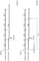
- FIGS. 4A to 4D are timing diagrams illustrating an example of the progress of a secure startup of the processing device 102.
- FIGS. 4A to 4D each represent two time lines representing the progress of a startup from the initialization (RESET) of the device 102.
- the upper line (NORMAL BOOT) of the Figures 4A to 4D corresponds to the launch of a startup sequence in the absence of a glitch attack.
- the initial value of TIL is 0, and this value is incremented three times during the startup sequence.
- the bottom line of the Figure 4A represents an example of starting the device 102 undergoing a “glitch” attack (GLITCH) when the TIL value is equal to 1.
- GLITCH a “glitch” attack
- the increment (+) of the TIL values is no longer applied after the arrival of the “glitch”, and the TIL value therefore remains frozen at 1.
- the startup sequence is then carried out while keeping the TIL value 1.
- the attacker then has access to the data associated with the value of TIL 1 even when the startup sequence is finished.
- the bottom line of the Figure 4B represents an example of starting the device 100 illustrating one mode of implementation of the method described.
- the protection circuit 113 is configured (TILPROTECT(3,x)) to force the value of TIL to be equal to 3 following a duration of x microseconds after the start of the startup sequence.
- a glitch attack occurs when the TIL value is 1.
- the startup sequence continues and the TIL value is not incremented to the value 2.
- a duration of x microseconds after the start of the startup sequence the protection circuit 113 forces the TIL value to be equal to the value 3.
- the data and/or codes associated with the TIL values 1 and 2 are then no longer accessible by the attacker.
- the bottom line of the Figure 4C represents an example of starting the processing device 102 similar to that of the Figure 4B .
- the protection circuit 113 is configured in the same way as in Figure 4B .
- a “glitch” attack (GLITCH) is carried out when the TIL value is still 0.
- the TIL values 1 and 2 are not protected, the startup sequence continues, while keeping the TIL value 0.
- a duration x microsecond after the start of the startup sequence the protection circuit 113 forces the TIL value to be equal to 3.
- the data and/or codes associated with the TIL values 0, 1 and 2 are then no longer accessible by attacking him.
- the bottom line of the figure 4D represents an example of starting the processing device 102 for which the protection circuit 113 is configured (TILPROTECT (1,y)) to force the value of TIL to be equal to 1 following a duration of y microseconds after the start of the startup sequence.
- TILPROTECT (1,y) a “glitch” attack
- GLITCH a “glitch” attack
- FIG. 5 is a flowchart representing the operations of a secure startup method of a processing device 102 according to an exemplary embodiment of the present description not covered by the invention. This method is implemented for example by the generic processor 110, the monotonic counter 106 and the access control circuit 108, of the processing device 102 of the Figure 1A .
- a step 501 the processing device 102 starts.
- this is the first start of the device 102 after its production.
- this involves a start-up carried out by an intermediate entity between the manufacturer of the device 102 and its end user.
- this involves a so-called start of operation of the electronic device 100 carried out by the end user.
- step 503 subsequent to step 501, the monotonic counter 106 is initialized to an initial value, being a natural integer.
- each power-up of the processing device 102 causes the initialization of the count value, for example to 0 or 1.
- each powering up of the processing device 102 causes the current count value to be replaced by the initial count value, for example equal to 0 or 1.
- the initial count value generated following a power-up may vary depending on the state, or context, of the processing device 102.
- one or more count values correspond to one or more levels of isolation reserved for an initial parameterization phase of the device 102, including for example the installation of firmware.
- the data and/or codes associated with these isolation levels are for example used for this initial parameterization.
- the processing device 102 has the context "blank" and the initial count value is equal to a value reserved for parameterization, such as 0.
- the context of the device becomes for example "parameterization completed".
- powering up the device 102 carried out for example by an intermediate entity between the manufacturer and the end user and/or by the end user, will then trigger a count value greater than the reserved count value , and for example equal to 1.
- the start code(s), as well as the sensitive data, associated with the isolation level corresponding to the reserved counting value will, therefore, be inaccessible.
- the context of the device is detected by the presence of a voltage on a start pin of the device, this voltage being applied for example by adding a jumper between the start pin and another pin to a supply voltage.
- the context of the device is detected by the value of one or more bits stored in a non-volatile manner, and in a protected manner, in memory 104, or in another memory.
- the generic processor 110 is arranged to detect the context of the device 102 when powering up the device 102, and to configure the initial count value of the monotonic counter 106 accordingly.
- the monotonic counter 106 is arranged to itself detect the context of the device 102 and to itself configure its initial counting value, when powering up the device 102.
- a step 505 (READ AND EXECUTE CODE ON LEVEL i)
- the data and the start codes associated with the isolation level i are read by the generic processor 110 and the start codes associated with the level isolation i are executed.
- N is equal to 2.
- step 509 the generic processor 110 triggers the increment of the count value .
- the count value changes from i to i+1. It is also possible that the increment increases the count value by several units. The process then resumes at step 505.
- the process ends in a step 511 (END OF BOOT) in which the startup of the processing device 102 ends.
- the current count value remains equal to N following step 511.
- the count value is incremented during step 511, and the current count value becomes equal at N+1.
- the access control circuit is then configured to prevent access to all start codes based on this count value.
- FIG. 6 is a flowchart representing the operations of a secure startup method of a processing device 102 according to another embodiment of the present description not covered by the invention. This method is implemented for example by the generic processor 110, the monotonic counter 106 and the access control circuit 108, of the processing device 102 of the Figure 1A .
- Steps 601 and 603 are similar to steps 501 and 503 of the figure 5 , and will not be described again in detail.
- step 605 (ACCESS CODE ON LEVELS i AND i+1, EXECUTE CODE ON LEVEL i)
- step 603 the data and startup codes associated with the isolation levels i+1 are accessible by the processor generic 110 and the startup code(s) associated with the isolation level i are executed.
- the data or codes associated with isolation level i contain one or more encryption keys, encrypted or not, which will be used during the execution of one or more codes associated with isolation level i+1 .
- write access is for example authorized on the memory area(s) associated with isolation level i+1 in order to provision the keys to the codes associated with isolation level i+1.
- the codes associated with isolation level i contain instructions aimed at verifying the integrity of the data and/or codes associated with isolation level i+1. Thus, read access to the memory zone(s) associated with isolation level i+1 is authorized in order to carry out this verification.
- step 607 subsequent to step 605, the count value is incremented. For example the count value goes from i to i+1. In other examples, the increment increases i by several units.
- the start of the processing device 102 ends with a step 615 (END OF BOOT), which is similar to step 511 of the figure 5 , and is not described again in detail.
- the process whose implementation is presented by the Figure 6 allows delayed start codes to be read.
- the start codes associated with an insulation level are read when the counting value is lower than the level value. This allows a saving of time compared to the implementation of the process presented in the figure 5 .
- An advantage of the embodiments described is that startup codes, as well as sensitive data in terms of confidentiality, are significantly protected against attacks, and in particular “glitch” attacks, by the use of a counter monotonic and a protection circuit as described in the present description.
- Another advantage of the embodiments described is that the protection mechanisms of a startup sequence are provided by hardware circuits.
Description
La présente description concerne le domaine des procédés et dispositifs pour la sécurité de circuits électroniques, et en particulier un dispositif et un procédé permettant d'effectuer un démarrage sécurisé d'un tel circuit.The present description concerns the field of methods and devices for the security of electronic circuits, and in particular a device and a method making it possible to carry out secure starting of such a circuit.
Le démarrage d'un dispositif de traitement est basé sur l'exécution de codes tels que des codes logiciels et/ou micrologiciels (en anglais "firmware"). La séquence de démarrage d'un dispositif est une étape sensible en termes de sécurité, car elle implique en général le réglage des paramètres liés à la sécurité du dispositif et/ou le traitement de données sensibles en termes de confidentialité, intégrité et authenticité telles que des clefs de chiffrement.The startup of a processing device is based on the execution of codes such as software and/or firmware codes. The startup sequence of a device is a sensitive step in terms of security, because it generally involves the adjustment of parameters related to the security of the device and/or the processing of sensitive data in terms of confidentiality, integrity and authenticity such as encryption keys.
Bien que des solutions existent pour rendre les codes de démarrage immuables et moins sensibles aux attaques extérieures, il serait souhaitable de protéger d'avantage l'accès à ces codes et aux données sensibles lors du démarrage d'un dispositif de traitement.Although solutions exist to make startup codes immutable and less susceptible to external attacks, it would be desirable to further protect access to these codes and sensitive data when starting a processing device.
Un mode de réalisation pallie tout ou partie des inconvénients des solutions existantes.One embodiment overcomes all or part of the drawbacks of existing solutions.
Un mode de réalisation prévoit un procédé comprenant :
- la protection d'une séquence de démarrage d'un dispositif de traitement par des incrémentations d'une valeur de comptage générée par un compteur monotone ;
- une première durée après le début de la séquence de démarrage, la comparaison, par le circuit de protection, entre la valeur de comptage et une première valeur de référence ; et
- si la valeur de comptage est inférieure à la première valeur de référence, la modification, par le circuit de protection, de la valeur de comptage en la première valeur de référence.
- protecting a startup sequence of a processing device by increments of a count value generated by a monotonic counter;
- a first duration after the start of the start-up sequence, the comparison, by the protection circuit, between the counting value and a first reference value; And
- if the count value is less than the first reference value, the modification, by the protection circuit, of the count value to the first reference value.
Selon un mode de réalisation, la valeur de comptage est stockée dans un registre du compteur monotone, la modification de la valeur de comptage en la première valeur de référence consistant en l'écrasement de la valeur de comptage par la première valeur de référence dans ledit registre.According to one embodiment, the count value is stored in a register of the monotonic counter, the modification of the count value into the first reference value consisting of overwriting the count value by the first reference value in said register.
Selon un mode de réalisation, le procédé comprend en outre la comparaison, par le circuit de protection, entre une valeur courante d'un compteur matériel cadencé par une horloge de référence avec une valeur seuil afin de déterminer si la première durée est atteinte.According to one embodiment, the method further comprises the comparison, by the protection circuit, between a current value of a hardware counter clocked by a reference clock with a threshold value in order to determine whether the first duration has been reached.
Selon un mode de réalisation, le procédé comprend en outre la désactivation du circuit de protection lorsque la première durée est atteinte.According to one embodiment, the method further comprises deactivation of the protection circuit when the first duration is reached.
Selon un mode de réalisation, le procédé comprend :
- après une deuxième durée, la comparaison, par le circuit de protection, entre la valeur de comptage et une deuxième valeur de référence ; et
- si la valeur de comptage est inférieure à la deuxième valeur de référence, la modification, par le circuit de protection, de la valeur de comptage en la deuxième valeur de référence.
- after a second duration, the comparison, by the protection circuit, between the counting value and a second reference value; And
- if the count value is less than the second reference value, the modification, by the protection circuit, of the count value to the second reference value.
Selon un mode de réalisation, le procédé comprend en outre la génération de la valeur de comptage par le compteur monotone lors d'une première phase de la séquence de démarrage.According to one embodiment, the method further comprises the generation of the count value by the monotonic counter during a first phase of the start-up sequence.
Selon un mode de réalisation, le procédé comprend :
- la transmission, par le compteur monotone, de la valeur de comptage à un circuit de contrôle d'accès d'une mémoire ; et
- la lecture, sur la base de la valeur de comptage, de premières données stockées dans la mémoire.
- transmitting, by the monotonic counter, the counting value to an access control circuit of a memory; And
- reading, based on the count value, first data stored in the memory.
Selon un mode de réalisation, la lecture des premières données est interdite par le circuit de contrôle d'accès sur la base de la première valeur de référence.According to one embodiment, reading of the first data is prohibited by the access control circuit on the basis of the first reference value.
Selon un mode de réalisation, les premières données comprennent des premiers codes de démarrage.According to one embodiment, the first data comprises first start codes.
Selon un mode de réalisation, le procédé comprend en outre la lecture, sur la base de la valeur de comptage, de deuxièmes données stockées dans la mémoire.According to one embodiment, the method further comprises reading, based on the count value, second data stored in the memory.
Un mode de réalisation prévoit un dispositif de traitement comprenant :
- un compteur monotone configuré pour protéger une séquence de démarrage du dispositif en incrémentant une valeur de comptage ; et
- un circuit de protection configuré pour :
- une première durée après le début de la séquence de démarrage, comparer la valeur de comptage avec une première valeur de référence ; et
- si la valeur de comptage est inférieure à la première valeur de référence, modifier la valeur de comptage en la première valeur de référence.
- a monotonic counter configured to protect a device startup sequence by incrementing a count value; And
- a protection circuit configured to:
- a first duration after the start of the start sequence, comparing the count value with a first reference value; And
- if the count value is less than the first reference value, changing the count value to the first reference value.
Selon un mode de réalisation, le circuit de protection est configuré en outre pour comparer une valeur courante d'un compteur matériel, cadencé par une horloge de référence, et une première valeur seuil afin de déterminer si la première durée est atteinte.According to one embodiment, the protection circuit is further configured to compare a current value of a hardware counter, clocked by a reference clock, and a first threshold value in order to determine whether the first duration has been reached.
Selon un mode de réalisation, le circuit de protection est configuré pour être désactivé lorsque la première durée est atteinte.According to one embodiment, the protection circuit is configured to be deactivated when the first duration is reached.
Selon un mode de réalisation, le compteur monotone est configuré pour transmettre la valeur de comptage à un circuit de contrôle d'accès d'une mémoire, le circuit de contrôle d'accès étant configuré pour :
- autoriser la lecture, sur la base de la valeur de comptage, de premières données stockées dans la mémoire ; et
- ne pas autoriser la lecture des premières données sur la base de la première valeur de référence.
- allowing reading, based on the count value, of first data stored in the memory; And
- do not allow reading of the first data based on the first reference value.
Selon un mode de réalisation, le circuit de contrôle d'accès est configuré en outre pour autoriser la lecture de deuxièmes données sur la base de la valeur de comptage.According to one embodiment, the access control circuit is further configured to allow reading of second data based on the count value.
Ces caractéristiques et avantages, ainsi que d'autres, seront exposés en détail dans la description suivante de modes de réalisation particuliers en relation avec les figures jointes parmi lesquelles :
- la
figure 1A représente, de façon schématique et sous forme de blocs, un mode de réalisation d'un dispositif de traitement selon un mode de réalisation de la présente description ; - la
figure 1B représente de façon schématique un circuit de protection selon un mode de réalisation de la présente description ; - la
figure 2 représente des données et codes accessibles lors d'un démarrage sécurisé selon un mode de réalisation de la présente description ; - la
figure 3 est un organigramme représentant des opérations d'un procédé de démarrage sécurisé d'un dispositif de traitement selon un exemple de réalisation de la présente description couvert par l'invention ; - la
figure 4A est un chronogramme représentant un exemple du déroulement d'un démarrage sécurisé d'un dispositif de traitement ; - la
figure 4B est un chronogramme représentant un exemple du déroulement d'un démarrage sécurisé d'un dispositif de traitement selon un exemple de réalisation de la présente description ; - la
figure 4C est un chronogramme représentant un autre exemple du déroulement d'un démarrage sécurisé d'un dispositif de traitement selon un exemple de réalisation de la présente description ; - la
figure 4D est un chronogramme représentant un autre exemple du déroulement d'un démarrage sécurisé d'un dispositif de traitement selon un exemple de réalisation de la présente description ; - la
figure 5 est un organigramme représentant des opérations d'un procédé de démarrage sécurisé d'un dispositif de traitement selon un exemple de réalisation de la présente description non couvert par l'invention ; et - la
figure 6 est un organigramme représentant des opérations d'un procédé de démarrage sécurisé d'un dispositif de traitement selon un autre exemple de réalisation de la présente description non couvert par l'invention.
- there
Figure 1A represents, schematically and in block form, an embodiment of a processing device according to an embodiment of the present description; - there
Figure 1B schematically represents a protection circuit according to one embodiment of the present description; - there
figure 2 represents data and codes accessible during a secure boot according to an embodiment of the present description; - there
Figure 3 is a flowchart representing the operations of a secure startup method of a processing device according to an exemplary embodiment of the present description covered by the invention; - there
figure 4A is a timing diagram representing an example of the progress of a secure startup of a processing device; - there
Figure 4B is a timing diagram representing an example of the progress of a secure startup of a processing device according to an exemplary embodiment of the present description; - there
Figure 4C is a timing diagram representing another example of the progress of a secure startup of a processing device according to an exemplary embodiment of the present description; - there
figure 4D is a timing diagram representing another example of the progress of a secure startup of a processing device according to an exemplary embodiment of the present description; - there
figure 5 is a flowchart representing the operations of a secure startup method of a processing device according to an exemplary embodiment of the present description not covered by the invention; And - there
Figure 6 is a flowchart representing the operations of a secure startup method of a processing device according to another embodiment of the present description not covered by the invention.
De mêmes éléments ont été désignés par de mêmes références dans les différentes figures. En particulier, les éléments structurels et/ou fonctionnels communs aux différents modes de réalisation peuvent présenter les mêmes références et peuvent disposer de propriétés structurelles, dimensionnelles et matérielles identiques.The same elements have been designated by the same references in the different figures. In particular, the structural and/or functional elements common to the different embodiments may have the same references and may have identical structural, dimensional and material properties.
Par souci de clarté, seuls les étapes et éléments utiles à la compréhension des modes de réalisation décrits ont été représentés et sont détaillés. En particulier, la conception de dispositifs de traitement est bien connue de la personne du métier et certains éléments n'ont pas été détaillés dans la description qui suit.For the sake of clarity, only the steps and elements useful for understanding the embodiments described have been represented and are detailed. In particular, the design of treatment devices is well known to the skilled person and certain elements have not been detailed in the description which follows.
Sauf précision contraire, lorsque l'on fait référence à deux éléments connectés entre eux, cela signifie directement connectés sans éléments intermédiaires autres que des conducteurs, et lorsque l'on fait référence à deux éléments reliés (en anglais "coupled") entre eux, cela signifie que ces deux éléments peuvent être connectés ou être reliés par l'intermédiaire d'un ou plusieurs autres éléments.Unless otherwise specified, when we refer to two elements connected to each other, this means directly connected without intermediate elements other than conductors, and when we refer to two elements connected (in English "coupled") to each other, this means that these two elements can be connected or be linked through one or more other elements.
Dans la description qui suit, lorsque l'on fait référence à des qualificatifs de position absolue, tels que les termes "avant", "arrière", "haut", "bas", "gauche", "droite", etc., ou relative, tels que les termes "dessus", "dessous", "supérieur", "inférieur", etc., ou à des qualificatifs d'orientation, tels que les termes "horizontal", "vertical", etc., il est fait référence sauf précision contraire à l'orientation des figures.In the following description, when referring to absolute position qualifiers, such as "front", "back", "up", "down", "left", "right", etc., or relative, such as the terms "above", "below", "superior", "lower", etc., or to qualifiers of orientation, such as the terms "horizontal", "vertical", etc., it is referred to unless otherwise specified in the orientation of the figures.
Sauf précision contraire, les expressions "environ", "approximativement", "sensiblement", et "de l'ordre de" signifient à 10 % près, de préférence à 5 % près.Unless otherwise specified, the expressions "approximately", "approximately", "substantially", and "of the order of" mean to the nearest 10%, preferably to the nearest 5%.
La
Le dispositif électronique 100 est par exemple une carte électronique telle qu'une carte à microcircuits, un matériel à usage informatique, ou un circuit à microprocesseur ou à microcontrôleur.The
Le dispositif de traitement 102 comprend par exemple une mémoire non volatile 104 (NV MEM), par exemple une mémoire flash. La mémoire 104 comprend, par exemple, une interface de contrôle d'accès 108 (ACCES CONTROL) reliée à un compteur monotone 106 (MONOTONIC COUNTER).The
Les compteurs monotones sont connus dans l'état de la technique, un exemple d'un tel compteur étant décrit dans la publication "
Le compteur monotone 106 est configuré de sorte qu'aucune commande, mise à part une remise à zéro du dispositif de traitement 102, ne permette de revenir à la valeur de comptage précédente. Dans le cas où la valeur de comptage est stockée de manière volatile, chaque mise hors alimentation du dispositif de traitement 102 engendre la perte de la valeur de comptage et à chaque remise sous tension du dispositif, le compteur monotone 106 génère à nouveau une valeur de comptage initiale. Dans le cas où la valeur de comptage est stockée dans un élément de mémorisation non volatile, à chaque redémarrage, une valeur de comptage initiale est par exemple réécrite dans l'élément de mémorisation non volatile du compteur monotone 106. La valeur de comptage est par exemple stockée dans un registre (non représenté) du compteur monotone 106.The
Le compteur monotone 106 est, en outre, couplé à un circuit de protection 113 (TIL PROTECTION). Par exemple, le circuit de protection 113 implémente une fonction de chien de garde (de l'anglais « watchdog »). Les fonctions de chiens de garde sont connues dans l'état de la technique et sont utilisées, par exemple, pour s'assurer qu'un circuit de traitement ne reste pas bloqué à une étape particulière du traitement qu'il effectue. Dans les modes de réalisation de la présente description, la fonction de chien de garde est employée afin de réduire le risque que le compteur monotone 106 reste bloqué à une valeur de comptage donnée. Le circuit de protection 113 est par exemple relié à un compteur 115 (TIMER). Le compteur 115 contient une valeur courante incrémentée par un signal d'horloge CLK. Le signal CLK est généré par exemple par un générateur d'horloge (non représentée) du dispositif 102, tel qu'un oscillateur quartz.The
Le dispositif de traitement 102 comprend en outre un processeur générique 110 (CPU). Par exemple, le processeur générique 110 est couplé par l'intermédiaire d'un bus 116 au compteur monotone 106 ainsi qu'à une mémoire RAM (mémoire à accès aléatoire) 112 et à la mémoire non volatile 104. La mémoire 112 et/ou la mémoire 104 mémorisent par exemple des instructions pour contrôler le processeur 110. Le processeur générique 110 est en outre couplé par l'intermédiaire du bus 116 à un processeur cryptographique 114 (CRYPTO). Le processeur cryptographique 114 reçoit, par l'intermédiaire du bus 116, des données chiffrées et retourne les données déchiffrées et/ou reçoit, par l'intermédiaire du bus 116, des données non chiffrées et retourne les données chiffrées.The
La mémoire non volatile 104 stocke par exemple plusieurs codes de démarrage, et/ou d'autres données, qui sont associés à plusieurs niveaux d'isolement TIL (de l'anglais "temporal isolation level"). Les codes de démarrage sont par exemple des codes logiciels et/ou micrologiciels. Dans l'exemple de la
Le niveau isolement TIL dépend de la valeur de comptage générée par le compteur monotone 106. Dans un exemple, la valeur TIL est égale à la valeur de comptage du compteur monotone 106, bien qu'il serait possible de modifier la valeur de comptage afin de générer la valeur TIL.The TIL isolation level depends on the count value generated by the
Lors d'un démarrage, la lecture des premier, deuxième et troisième codes et/ou données et/ou l'exécution des premier, deuxième et troisième codes de démarrage, sont effectuées par étapes, chaque étape étant associée à un niveau d'isolement correspondant. Le circuit de contrôle d'accès 108 de la mémoire 104 est configuré de sorte que la lecture de ces codes/données soit contrôlée en fonction du niveau d'isolement de l'étape. Les premières données et/ou le premier code sont par exemple associés au niveau d'isolement, ou valeur de TIL, 0 et le circuit de contrôle d'accès 108 est configuré pour que ces données et/ou code soient uniquement accessibles pour lecture lorsque la valeur de comptage TIL courante est égale à 0. Lorsque la valeur de comptage est incrémentée, par exemple suite à l'exécution du premier code, le circuit de contrôle d'accès 108 verrouille la zone 118, les premières données et/ou le premier code ne sont alors plus accessibles en lecture. Suite à une incrémentation, la valeur de comptage courante passe par exemple à 1 et les données et/ou les codes de démarrage associés au niveau d'isolement 1, par exemple le deuxième code de démarrage, sont exécutés.During a start, the reading of the first, second and third codes and/or data and/or the execution of the first, second and third start codes are carried out by steps, each step being associated with a corresponding isolation level. The
Dans certains cas, le circuit de contrôle d'accès 108 est configuré pour permettre la lecture d'une ou plusieurs données associées à des niveaux d'isolement supérieurs à celui de la valeur TIL courante. Par exemple, dans certains modes de réalisation, plus le niveau d'isolement est bas, plus le niveau de protection est important. Le niveau d'isolement 0 est donc le niveau assurant le plus de protection, car les données correspondantes peuvent être lues uniquement lorsque la valeur de comptage est égale à 0. Ainsi, chaque niveau d'isolement correspond à un niveau de protection du contenu des zones mémoire lui étant associé.In certain cases, the
Le mécanisme de contrôle d'accès implémenté par le circuit 108 peut être mis en oeuvre de plusieurs manières.The access control mechanism implemented by
Dans un premier exemple, quand le circuit 108 reçoit une demande de lecture associée à une ou plusieurs adresses dans la mémoire 104, il est configuré pour comparer cette/ces adresse (s) aux plages d'adresses associées aux zones 118, 120, 122 de la mémoire 104. S'il s'agit d'une adresse dans une zone associée à une valeur de TIL inférieure à la valeur courante, le circuit 108 est par exemple configuré pour bloquer l'opération de lecture.In a first example, when
Dans un deuxième exemple, le circuit 108 est configuré pour désactiver un circuit de lecture de toute zone 118, 120, 122 de la mémoire 104 associée à une valeur de TIL inférieure à la valeur courante. Par exemple, une ou plusieurs portes logiques, telles que des portes OU ou des portes ET, sont couplées dans le chemin de sortie de chaque zone 118, 120 et 122 de la mémoire 104 et reçoivent également un signal d'activation généré sur la base de la valeur de TIL permettant de désactiver sélectivement chaque chemin de sortie.In a second example,
Le fait que la valeur de comptage ne puisse pas être décrémentée lors de la période de fonctionnement du dispositif 100 permet la protection des codes de démarrage une fois leur exécution faite, car le circuit de contrôle d'accès 108 empêche la lecture des données et/ou l'exécution des codes associés à des niveaux d'isolement TIL inférieurs au niveau courant.The fact that the counting value cannot be decremented during the operating period of the
Dans certains modes de réalisation, une ou plusieurs des données et/ou codes de démarrage et les niveaux d'isolement associés sont réservés à des phases de paramétrisation du dispositif 102 ou à des entités distinctes dans la chaîne allant du fabriquant jusqu'à l'utilisateur final. Par exemple, une entité intermédiaire entre le fabriquant du dispositif de traitement 102 et l'utilisateur final du dispositif électronique 100 peut être amenée à installer des données et/ou codes de démarrage qui sont propres à l'utilisation du dispositif 100. Dans ce cas, une ou plusieurs des données et/ou codes de démarrage les plus « bas », par exemple associés au niveau d'isolement 0, sont par exemple réservés au fabricant du dispositif de traitement 102, et d'autres données et/ou codes de démarrage sont réservés à l'entité intermédiaire.In certain embodiments, one or more of the data and/or startup codes and the associated isolation levels are reserved for parameterization phases of the
Le contenu des zones mémoire 118, 120 et 122 comprend, dans certains modes de réalisation, d'autres données en plus des codes de démarrage du dispositif de traitement 102. Par exemple, d'autres données sensibles en termes de confidentialité sont stockées en association avec au moins un des premier, deuxième et troisième codes et/ou données. Par exemple, ces autres données comprennent des clefs de chiffrement utilisées lors de l'exécution des codes de démarrage leur étant associés. Dans l'exemple de la
Bien que les protections assurées par le compteur monotone 106 et le circuit de contrôle d'accès 108 permettent de sécuriser la séquence de démarrage dans la plupart des cas, il reste un risque d'attaque par signaux transitoires (en anglais « glitch attack »), décrit plus en détail ci-dessous.Although the protections provided by the
Par exemple, si une attaque en « glitch » est menée lorsque la valeur de TIL est égale à 0, il risque d'être possible de figer la valeur de TIL à ce niveau, et l'attaquant aurait donc accès aux données et/ou codes associés à la valeur de TIL 0 à tout moment de la vie du dispositif 100.For example, if a glitch attack is carried out when the TIL value is equal to 0, it may be possible to freeze the TIL value at this level, and the attacker would therefore have access to the data and/or codes associated with the value of TIL 0 at any time during the life of the
Pour contrer ce type d'attaque, à chaque démarrage du dispositif 102, le circuit de protection 113 est par exemple configuré pour forcer automatiquement la valeur de TIL à être égale à une valeur donnée après une durée prédéterminée après le début de la séquence de démarrage.To counter this type of attack, each time the
La
A titre d'exemple, le circuit de protection 113 comprend des comparateurs 124 et 126. Le comparateur 124 reçoit un signal correspondant à une valeur courante COUNT de la valeur de comptage générée par le compteur 115 et la compare à une valeur seuil xT. La valeur seuil xT représente par exemple une durée de référence. Cette comparaison s'effectue par exemple de façon continue, ou à chaque cycle de l'horloge, jusqu'à ce que la valeur COUNT soit supérieure ou égale à la valeur xT. Lorsque la valeur COUNT est supérieure ou égale à xT, une comparaison par le comparateur 126 est par exemple déclenchée. Le comparateur 126 compare la valeur de TIL courante du compteur monotone 106 avec une valeur de référence N. La valeur de référence N correspond à la valeur de TIL qui devrait être courante suite à la durée de référence, correspondant à xT, après le début d'une séquence de démarrage.For example, the
Si la valeur de TIL reçue par le comparateur 126 au moment de la comparaison est strictement inférieure à la valeur de référence N, le comparateur 126 transmet un signal au compteur monotone 106 déclenchant, par exemple, une ou plusieurs incrémentations du compteur monotone 106, afin que la valeur de TIL devienne égale au moins à la valeur de référence N. La valeur de référence N est alors transmise au circuit de contrôle d'accès 108, ce qui a pour conséquence d'interdire l'accès aux données de la mémoire associées à des valeurs de TIL inférieures à N.If the TIL value received by the
Selon un autre mode de réalisation, le comparateur 126 envoie la valeur de référence N au compteur monotone 106 afin de forcer le changement de la valeur de TIL vers cette valeur de référence N. Afin d'éviter l'écrasement de la valeur de comptage par une valeur inférieure, le compteur monotone 106 est par exemple configuré pour interdire l'écrasement de sa valeur courante par une valeur inférieure.According to another embodiment, the
La
Lors d'une première étape 200 de démarrage du dispositif de traitement 102 illustrée en haut de la
Par exemple, une fois que le premier code (CODE0) est exécuté, le processeur générique 110 commande une première incrémentation de la valeur de comptage courante par le compteur monotone 106. Par exemple, le premier code comprend une commande demandant l'incrémentation du compteur. Cette commande est par exemple transmise vers un registre de commande (non illustré) du compteur monotone 106.For example, once the first code (CODE0) is executed, the
Après cette première incrémentation, la valeur de comptage courante du compteur monotone 106 est par exemple égale à 1, correspondant à la deuxième étape 201 du démarrage. Le circuit de contrôle d'accès 108 reçoit la nouvelle valeur de comptage courante, et est configuré pour empêcher, sur la base de cette valeur de comptage supérieure à 0, tout accès au premier code ainsi qu'aux premières données qui sont associées au niveau d'isolation 0. Autrement dit, les zones mémoires 118 et 204 sont verrouillées sur la base de toute valeur de comptage strictement supérieure à 0.After this first increment, the current count value of the
Le niveau d'isolation 1 est associé à un deuxième code (CODE1) contenu dans la zone 120 ainsi qu'à des deuxièmes données (KEY1) contenues dans la zone 202. Selon un mode de réalisation, le troisième code (CODE2), par exemple associé au niveau d'isolation 2 et contenu dans la zone 122, est accessible pour lecture sur la base de la valeur de comptage courante égale à 1.
Par exemple, une fois que le deuxième code (CODE1) est exécuté, le processeur générique 110 commande une deuxième incrémentation de la valeur de comptage courante par le compteur monotone 106. Par exemple, après cette deuxième incrémentation, la valeur de comptage courante du compteur monotone 106 est égale à 2, correspondant à la troisième étape 203 du démarrage. Le niveau d'isolation 2 est associé au troisième code (CODE2) ainsi qu'à des troisièmes données (KEY2). Le circuit de contrôle d'accès 108 reçoit la nouvelle valeur de comptage, et est configuré pour empêcher, sur la base de cette valeur de comptage supérieure à 1, tout accès au premier et au deuxième codes ainsi qu'aux premières et aux deuxièmes données qui sont associés aux niveaux d'isolation inférieurs ou égaux à 1.For example, once the second code (CODE1) is executed, the
Selon un mode de réalisation, lorsque le dernier code de démarrage est exécuté, par exemple le troisième code de démarrage, le processeur générique 110 commande une troisième incrémentation de la valeur de comptage courante par le compteur monotone 106. Le circuit de contrôle d'accès 108 verrouille alors tout accès aux premier, deuxième et troisième codes de démarrage ainsi qu'aux premières, deuxièmes et troisièmes données.According to one embodiment, when the last start code is executed, for example the third start code, the
Selon un autre mode de réalisation, lorsque le dernier code de démarrage est exécuté, par exemple le troisième code de démarrage, la valeur de comptage courante n'est pas incrémentée par le compteur monotone 106 et l'accès au troisième code de démarrage ainsi qu'aux troisièmes données reste autorisé par le circuit de contrôle d'accès.According to another embodiment, when the last start code is executed, for example the third start code, the current count value is not incremented by the
La
Dans une étape 300 (LAUNCH BOOT SEQUENCE AT TIL0 AND START COUNT), le dispositif 102 est réinitialisé et une séquence de démarrage débute. Le compteur monotone 106 génère alors une première valeur de TIL, par exemple égale à 0. Le compteur 115 est initialisé et une valeur courante COUNT du compteur 115 est incrémentée à chaque cycle de l'horloge du dispositif 102.In a step 300 (LAUNCH BOOT SEQUENCE AT TIL0 AND START COUNT), the
Dans certains cas, dans une opération 301 (TILPROTECT(M;x1)), le circuit de protection 113 est configuré pour déclencher l'incrémentation de la valeur de TIL à la valeur M, une durée x1 après le début de la séquence de démarrage. Par exemple, cette opération 301 comprend la configuration d'une valeur de référence M et d'une valeur seuil x1 dans un registre. Dans d'autres modes de réalisation, ces valeurs sont invariables et stockées de façon non volatile dans une mémoire du dispositif 100.In certain cases, in an operation 301 (TILPROTECT (M;x1)), the
De manière facultative, dans une opération 302 (TILPROTECT(N;x2)), le circuit de protection 113 peut aussi être configuré pour déclencher l'incrémentation de la valeur de TIL à la valeur N, une durée x2 après le début de la séquence de démarrage. Comme pour l'opération 301, cette opération 302 comprend par exemple la configuration d'une valeur de référence N et d'une valeur seuil x2 dans un registre. Dans d'autres modes de réalisation, ces valeurs sont invariables et stockées de façon non volatile dans une mémoire du dispositif 100.Optionally, in an operation 302 (TILPROTECT(N;x2)), the
Les procédés de protection sur la base d'une ou plusieurs durées xT sont par exemple implémentés en parallèle, la
Le procédé 303 comprend des étapes 304 à 306.The
Dans une étape 304 (COUNT<x1 ?), le comparateur 124 du circuit de protection 113 compare la valeur courante COUNT du compteur 115 avec la valeur x1. Si la valeur COUNT est strictement inférieure à la valeur x1 (branche Y), le procédé reprend sur cette même étape 304. Si la valeur COUNT est supérieure ou égale à la valeur x1 (branche N), le comparateur 126 compare la valeur de TIL courante du compteur monotone 106 avec la valeur M (bloc 305, TIL≥M). Si la valeur de TIL courante est supérieure ou égale à la valeur M, le procédé se termine dans une étape 307 (END). Dans le cas où la valeur de TIL courante est strictement inférieure à la valeur M, la valeur du TIL est forcée à la valeur M dans une opération 306. Par exemple, soit la valeur de comptage de compteur monotone 106 est incrémentée d'une ou plusieurs unités jusqu'à ce que la valeur de TIL soit égale à la valeur M, soit la valeur de TIL courante est écrasée du registre du compteur monotone 106 par la valeur M. Après l'opération 303, le procédé se termine dans l'étape 307 (END).In a step 304 (COUNT<x1?), the
Dans certains cas, seul le procédé 303 est implémenté. A titre d'exemple, dans un usage normal, c'est-à-dire sans attaque en « glitch », la valeur de TIL 2 est par exemple atteinte en moins de 5 microsecondes suite au lancement de la séquence de démarrage. Le circuit de protection 113 est alors uniquement configuré pour déclencher automatiquement l'incrémentation de la valeur de TIL à la valeur 2, 5 microsecondes après le début de la séquence de démarrage. Dans le cas où la valeur de TIL est déjà égale à 2, le circuit de protection 113 est par exemple désactivé.In some cases,
Dans le cas où le procédé 303' est également implémenté, en parallèle du procédé 303, le procédé 303' comprend des opérations 304', 305' et 306' similaires aux opérations 304, 305 et 306, sauf que la valeur seuil x1 est remplacée par la valeur seuil x2 dans l'opération 304', et la valeur de référence M est remplacée par la valeur de référence N dans les opérations 305' et 306'. Les comparaisons faites dans les opérations 304' et 305' sont par exemple implémentées par un autre circuit similaire à celui de la
A titre d'exemple, dans le cas où les procédés 303 et 303' sont implémentés, le circuit de protection est alors configuré pour déclencher automatiquement l'incrémentation de la valeur de TIL à la valeur 2, par exemple 5 microsecondes après le début de la séquence de démarrage, et en parallèle pour déclencher automatiquement l'incrémentation de la valeur de TIL à la valeur 3, par exemple 10 microsecondes après le début de la séquence de démarrage. Le circuit de protection 113 est par exemple désactivé dès lors que la valeur de TIL courante est égale à 3.For example, in the case where the
Il est possible de protéger une pluralité de niveaux de TIL en réalisant une pluralité d'étapes similaires aux étapes 304 à 306 et aux étapes 304' à 306' avec des valeurs de références différentes des valeurs M et N associées à des valeurs différentes de x1 et de x2.It is possible to protect a plurality of TIL levels by carrying out a plurality of steps similar to
Les
Les
Dans l'exemple des
Les lignes inférieures des
La ligne inférieure de la
La ligne inférieure de la
La ligne inférieure de la
La ligne inférieure de la
Dans l'exemple de la
La
Dans une étape 501 (LAUNCH BOOT SEQUENCE) le dispositif de traitement 102 démarre. Dans un exemple il s'agit du premier démarrage du dispositif 102 après sa production. Dans un autre exemple il s'agit d'un démarrage effectué par une entité intermédiaire entre le fabriquant du dispositif 102 et son utilisateur final. Encore dans un autre exemple, il s'agit d'un démarrage dit de fonctionnement du dispositif électronique 100 effectué par l'utilisateur final.In a step 501 (LAUNCH BOOT SEQUENCE) the
Dans une étape 503 (INITIALIZE COUNTER), postérieure à l'étape 501, le compteur monotone 106 est initialisé à une valeur initiale, étant un entier naturel. Dans l'exemple dans lequel la valeur de comptage est stockée de manière volatile, chaque mise sous tension du dispositif de traitement 102 engendre l'initialisation de la valeur de comptage, par exemple à 0 ou à 1. Dans un autre exemple dans lequel la valeur de comptage est stockée sur des éléments de mémorisation non volatile, chaque mise sous tension du dispositif de traitement 102 engendre le remplacement de la valeur de comptage courante par la valeur de comptage initiale, par exemple égale à 0 ou à 1.In a step 503 (INITIALIZE COUNTER), subsequent to step 501, the
Dans certains modes de réalisation, la valeur de comptage initiale générée suite à une mise sous tension peut varier selon l'état, ou contexte, du dispositif de traitement 102. Par exemple, une ou plusieurs valeurs de comptage correspondent à un ou plusieurs niveaux d'isolation réservés à une phase de paramétrisation initiale du dispositif 102, comprenant par exemple l'installation de micrologiciels. Les données et/ou codes associés à ces niveaux d'isolement sont par exemple utilisés pour cette paramétrisation initiale.In certain embodiments, the initial count value generated following a power-up may vary depending on the state, or context, of the
Par exemple, suite à la fabrication, le dispositif de traitement 102 a le contexte "vierge" et la valeur de comptage initiale est égale à une valeur réservée à la paramétrisation, telle que 0. Une fois la paramétrisation achevée, le contexte du dispositif devient par exemple "paramétrisation achevée". Avec ce nouveau contexte, la mise sous tension du dispositif 102, effectuée par exemple par une entité intermédiaire entre le fabriquant et l'utilisateur final et/ou par l'utilisateur final, déclenchera alors une valeur de comptage supérieure à la valeur de comptage réservée, et par exemple égale à 1. Le ou les codes de démarrage, ainsi que les données sensibles, associés au niveau d'isolement correspondant à la valeur de comptage réservée seront, par conséquent, inaccessibles.For example, following manufacturing, the
Par exemple, le contexte du dispositif est détecté par la présence d'une tension sur une broche de démarrage du dispositif, cette tension étant appliquée par exemple par l'ajout d'un cavalier (en anglais "jumper") entre la broche de démarrage et une autre broche à une tension d'alimentation. A titre complémentaire ou alternatif, le contexte du dispositif est détecté par la valeur d'un ou plusieurs bits stockés de façon non volatile, et de manière protégée, dans la mémoire 104, ou dans une autre mémoire.For example, the context of the device is detected by the presence of a voltage on a start pin of the device, this voltage being applied for example by adding a jumper between the start pin and another pin to a supply voltage. As a complement or alternative, the context of the device is detected by the value of one or more bits stored in a non-volatile manner, and in a protected manner, in
Dans un exemple, le processeur générique 110 est agencé pour détecter le contexte du dispositif 102 lors de la mise sous tension du dispositif 102, et pour configurer en conséquence la valeur de comptage initiale du compteur monotone 106. Dans un autre exemple, le compteur monotone 106 est agencé pour détecter lui-même le contexte du dispositif 102 et pour configurer lui-même sa valeur de comptage initiale, lors de la mise sous tension du dispositif 102.In one example, the
Dans une étape 505 (READ AND EXECUTE CODE ON LEVEL i), postérieure à l'étape 503, les données et les codes de démarrage associés au niveau d'isolement i sont lus par le processeur générique 110 et les codes de démarrage associés au niveau d'isolement i sont exécutés. Une fois les codes du niveau i exécutés, le processeur générique 110 compare, dans une étape 507 (i=N ?) la valeur de comptage i à la valeur N, N étant la valeur de comptage associée à la dernière étape dans la séquence de démarrage, autrement dit les codes de démarrage du niveau d'isolement N sont les derniers à être exécutés selon le mode de réalisation de la présente description. Par exemple, dans l'exemple de la
Dans le cas où, suite à l'étape de comparaison 507, la valeur de comptage est égale à N (branche Y), le procédé se termine sur une étape 511 (END OF BOOT) dans laquelle le démarrage du dispositif de traitement 102 se termine. Selon un mode de réalisation, la valeur de comptage courante reste égale à N suite à l'étape 511. Selon un autre mode de réalisation, la valeur de comptage est incrémentée lors de l'étape 511, et la valeur de comptage courante devient égale à N+1. Dans ce deuxième cas, le circuit de contrôle d'accès est alors configuré pour empêcher tout accès à tous les codes de démarrage sur la base de cette valeur de comptage.In the case where, following the
La
Les étapes 601 et 603 sont similaires aux étapes 501 et 503 de la
Dans une étape 605 (ACCESS CODE ON LEVELS i AND i+1, EXECUTE CODE ON LEVEL i), postérieure à l'étape 603, les données et les codes de démarrage associés aux niveaux d'isolement i+1 sont accessibles par le processeur générique 110 et le ou les codes de démarrage associés au niveau d'isolement i sont exécutés.In a step 605 (ACCESS CODE ON LEVELS i AND i+1, EXECUTE CODE ON LEVEL i), subsequent to step 603, the data and startup codes associated with the isolation levels i+1 are accessible by the processor generic 110 and the startup code(s) associated with the isolation level i are executed.
Dans un exemple, les données ou codes associés au niveau d'isolement i contiennent une ou plusieurs clefs de chiffrement, chiffrées ou non, qui seront utilisées lors de l'exécution d'un ou plusieurs codes associés au niveau d'isolement i+1. Ainsi, un accès pour écriture est par exemple autorisé sur la ou les zones mémoire associées au niveau d'isolement i+1 afin de provisionner les clefs aux codes associés au niveau d'isolement i+1.In an example, the data or codes associated with isolation level i contain one or more encryption keys, encrypted or not, which will be used during the execution of one or more codes associated with isolation level i+1 . Thus, write access is for example authorized on the memory area(s) associated with isolation level i+1 in order to provision the keys to the codes associated with isolation level i+1.
Dans un autre exemple, les codes associés au niveau d'isolement i contiennent des instructions visant à vérifier l'intégrité des données et/ou codes associés au niveau d'isolement i+1. Ainsi, un accès en lecture de la ou des zones mémoire associées au niveau d'isolement i+1 est autorisé afin d'effectuer cette vérification.In another example, the codes associated with isolation level i contain instructions aimed at verifying the integrity of the data and/or codes associated with isolation level i+1. Thus, read access to the memory zone(s) associated with isolation level i+1 is authorized in order to carry out this verification.
Dans une étape 607 (i=i+1), postérieure à l'étape 605, la valeur de comptage est incrémentée. Par exemple la valeur de comptage passe de i à i+1. Dans d'autres exemples, l'incrémentation augmente i de plusieurs unités.In a step 607 (i=i+1), subsequent to step 605, the count value is incremented. For example the count value goes from i to i+1. In other examples, the increment increases i by several units.
Dans une étape 609 (i=N ?) le processeur générique 110 compare la valeur de comptage i à la valeur N, où N est défini comme décrit en relation avec l'étape 607 de la
Dans le cas où, lors de l'étape de comparaison 609, la valeur de comptage est égale à N (branche Y), le procédé continue sur une étape 613 (EXECUTE CODE ON LEVEL N) dans laquelle le ou les codes de démarrage associés au niveau d'isolation N sont exécutés.In the case where, during the
Le démarrage du dispositif de traitement 102 se termine par une étape 615 (END OF BOOT), qui est similaire à l'étape 511 de la
Le procédé dont la mise en oeuvre est présentée par la
Un avantage des modes de réalisation décrits est que des codes de démarrage, ainsi que des données sensibles en termes de confidentialité, sont protégés de façon importante contre des attaques, et notamment des attaques en « glitch », par l'usage d'un compteur monotone et d'un circuit de protection tel que décrit dans la présente description.An advantage of the embodiments described is that startup codes, as well as sensitive data in terms of confidentiality, are significantly protected against attacks, and in particular “glitch” attacks, by the use of a counter monotonic and a protection circuit as described in the present description.
Un autre avantage des modes de réalisation décrits est que les mécanismes de protection d'une séquence de démarrage sont assurés par des circuits matériels.Another advantage of the embodiments described is that the protection mechanisms of a startup sequence are provided by hardware circuits.
Divers modes de réalisation et variantes ont été décrits. La personne du métier comprendra que certaines caractéristiques de ces divers modes de réalisation et variantes pourraient être combinées, et d'autres variantes apparaîtront à la personne du métier. En particulier, le nombre de niveaux d'isolement ainsi que le nombre de protections des niveaux d'isolement peuvent varier. De plus, bien que des exemples de comparaisons ont été décrits sur la base de certains opérateurs tels que strictement inférieur ou supérieur ou égal, selon la définition des valeurs seuil ou de référence, les opérateurs peuvent varier.Various embodiments and variants have been described. Those skilled in the art will understand that certain features of these various embodiments and variations could be combined, and other variations will become apparent to those skilled in the art. In particular, the number of isolation levels as well as the number of isolation level protections may vary. Additionally, although examples of comparisons have been described based on certain operators such as strictly less or greater or equal, depending on the definition of threshold or reference values, the operators may vary.
Enfin, la mise en oeuvre pratique des modes de réalisation et variantes décrits est à la portée de la personne du métier à partir des indications fonctionnelles données ci-dessus.Finally, the practical implementation of the embodiments and variants described is within the reach of those skilled in the art based on the functional indications given above.
Claims (15)
- Method comprising:- the protection of a boot sequence of a processing device (102) by incrementations of a counting value (TIL) generated by a monotonic counter (106);- a first time period (x) after the beginning of the boot sequence (RESET), the comparison, by the protection circuit (113), between the counting value and a first reference value (M); and- if the counting value is smaller than the first reference value, the modification, by the protection circuit (113), of the counting value into the first reference value.
- Method according to claim 1, wherein the counting value (TIL) is stored in a register of the monotonic counter (106), the modification of the counting value into the first reference value (M) comprising overwriting the counting value with the first reference value in said register.
- Method according to claim 1 or 2, further comprising the comparison, by protection circuit (113), between a current value (COUNT) of a hardware counter (115) rated by a reference clock with a threshold value (xT, x1) to determine whether the first time period (x) has been reached.
- Method according to any of claims 1 to 3, further comprising the deactivation of the protection circuit (113) when the first time period (x) is reached.
- Method according to any of claims 1 to 4, comprising:- after a second time period (y), the comparison, by the protection circuit (113), between the counting value (TIL) and a second reference value (x2); and- if the counting value is smaller than the second reference value (N), the modification, by the protection circuit (113), of the counting value into the second reference value (N).
- Method according to any of claims 1 to 5, further comprising the generation of the counting value (TIL) by the monotonic counter (106) during a first phase of the boot sequence.
- Method according to any of claims 1 to 6, comprising:- the transmission, by the monotonic counter (106), of the counting value (TIL) to a circuit for controlling the access (108) to a memory (104); and- the reading, on the basis of the counting value, of first data (118) stored in the memory.
- Method according to claim 7, wherein the reading of the first data (118) is forbidden by the access control circuit (108) on the basis of the first reference value (M) .
- Method according to claim 7 or 8, wherein the first data (118) comprise first boot codes.
- Method according to any of claims 7 to 9, further comprising the reading, on the basis of the counting value (TIL), of second data stored in the memory (120, 122) .
- Processing device (102) comprising:- a monotonic counter (106) configured to protect a boot sequence of the device by incrementing a counting value (TIL); and- a protection circuit (113) configured to:- a first time period (x, y) after the beginning of the boot sequence, compare the counting value with a first reference value (M, N); and- if the counting value is smaller than the first reference value, modify the counting value into the first reference value.
- Processing device (102) according to claim 11, wherein the protection circuit (113) is further configured to compare a current value (COUNT) of a hardware counter (115), rated by a reference clock, and a first threshold value (xT, x1, x2) to determine whether the first time period (x, y) is reached.
- Processing device (102) according to claim 11 or 12, wherein the protection device (113) is configured to be deactivated when the first time period (x, y) has been reached.
- Processing device (102) according to any of claims 11 to 13, wherein:- the monotonic counter (106) is configured to transmit the counting value (TIL) to a circuit for controlling the access (108) to a memory (104), the access control circuit being configured to:- authorize the reading, on the basis of the counting value, of first data (118) stored in the memory; and- not authorize the reading of the first data on the basis of the first reference value (M, N).
- Processing device (102) according to claim 14, wherein the access control circuit (108) is further configured to authorize the reading of second data (120, 122) on the basis of the counting value (TIL).
Applications Claiming Priority (1)
| Application Number | Priority Date | Filing Date | Title |
|---|---|---|---|
| FR2108928A FR3126572B1 (en) | 2021-08-26 | 2021-08-26 | Secure start of a processing unit |
Publications (2)
| Publication Number | Publication Date |
|---|---|
| EP4145704A1 EP4145704A1 (en) | 2023-03-08 |
| EP4145704B1 true EP4145704B1 (en) | 2024-02-07 |
Family
ID=79269633
Family Applications (1)
| Application Number | Title | Priority Date | Filing Date |
|---|---|---|---|
| EP22191050.8A Active EP4145704B1 (en) | 2021-08-26 | 2022-08-18 | Secure starting of a processing unit |
Country Status (4)
| Country | Link |
|---|---|
| US (1) | US11934529B2 (en) |
| EP (1) | EP4145704B1 (en) |
| CN (1) | CN115935443A (en) |
| FR (1) | FR3126572B1 (en) |
Family Cites Families (12)
| Publication number | Priority date | Publication date | Assignee | Title |
|---|---|---|---|---|
| US8332653B2 (en) | 2004-10-22 | 2012-12-11 | Broadcom Corporation | Secure processing environment |
| US20060198515A1 (en) * | 2005-03-03 | 2006-09-07 | Seagate Technology Llc | Secure disc drive electronics implementation |
| US8184812B2 (en) | 2009-06-03 | 2012-05-22 | Freescale Semiconductor, Inc. | Secure computing device with monotonic counter and method therefor |
| EP2449499B1 (en) * | 2009-07-01 | 2014-11-26 | Panasonic Corporation | Secure boot method and secure boot apparatus |
| EP2503482A1 (en) * | 2011-03-23 | 2012-09-26 | ST-Ericsson SA | Electronic device with flash memory component |
| US10659054B2 (en) | 2018-02-23 | 2020-05-19 | Nxp B.V. | Trusted monotonic counter using internal and external non-volatile memory |
| US10719607B2 (en) | 2018-03-19 | 2020-07-21 | Nxp B.V. | Data integrity verification in a non-volatile memory |
| GB201809526D0 (en) | 2018-06-11 | 2018-07-25 | Wibu Systems Ltd | Key protection device |
| US10868679B1 (en) | 2019-07-25 | 2020-12-15 | Cypress Semiconductor Corporation | Nonvolatile memory device with regions having separately programmable secure access features and related methods and systems |
| EP3933630A1 (en) * | 2020-06-30 | 2022-01-05 | Nxp B.V. | Method and apparatus to adjust system security policies based on system state |
| US11784827B2 (en) | 2021-03-09 | 2023-10-10 | Micron Technology, Inc. | In-memory signing of messages with a personal identifier |
| FR3121526A1 (en) | 2021-03-31 | 2022-10-07 | STMicroelectronics (Alps) SAS | Secure start of a processing unit |
-
2021
- 2021-08-26 FR FR2108928A patent/FR3126572B1/en active Active
-
2022
- 2022-08-18 EP EP22191050.8A patent/EP4145704B1/en active Active
- 2022-08-25 US US17/822,272 patent/US11934529B2/en active Active
- 2022-08-26 CN CN202211037309.9A patent/CN115935443A/en active Pending
Also Published As
| Publication number | Publication date |
|---|---|
| EP4145704A1 (en) | 2023-03-08 |
| US20230069651A1 (en) | 2023-03-02 |
| US11934529B2 (en) | 2024-03-19 |
| FR3126572A1 (en) | 2023-03-03 |
| CN115935443A (en) | 2023-04-07 |
| FR3126572B1 (en) | 2023-08-25 |
Similar Documents
| Publication | Publication Date | Title |
|---|---|---|
| EP2280364B1 (en) | Faults injection detector in an integrated circuit | |
| EP0826169B1 (en) | Improved integrated circuit and method for using same | |
| US20170228543A1 (en) | Firmware protection and validation | |
| EP1605333B1 (en) | Program execution control | |
| EP4068128A1 (en) | Secure starting of a processing unit | |
| WO2005101160A1 (en) | Method and device for controlling an access to peripherals | |
| FR3072195B1 (en) | METHOD FOR MANAGING RETURN OF PRODUCT FOR ANALYSIS AND CORRESPONDING PRODUCT | |
| WO2007049181A1 (en) | Semiconductor device and method for preventing attacks on the semiconductor device | |
| EP3633495B1 (en) | Method for managing a dvfs power supply and corresponding system | |
| EP1220101B1 (en) | Method and device for protecting against unauthorised use of integrated circuits | |
| EP4145704B1 (en) | Secure starting of a processing unit | |
| US20190123900A1 (en) | Rekeying keys for encrypted data in nonvolatile memories | |
| EP3441902B1 (en) | Method for protecting an electronic device against fault-injection attacks | |
| EP1633074A1 (en) | Integrated circuit with coded securing signal, securing method, device and coded securing signal via a corresponding dynamic key. | |
| EP3042334B1 (en) | Method of setting up safety means depending on a trust indicia varying before and after command execution in an electronic device with memory, and device for implementing said method | |
| WO2023117270A1 (en) | Module and method for securing a computer device | |
| EP2955661B1 (en) | Protection of data stored in a volatile memory | |
| FR3121530A1 (en) | Method and device for secure decryption of encrypted data | |
| FR2752993A1 (en) | Non-volatile memory data protection device with time switching circuit | |
| EP3493182B1 (en) | Method and device for cryptographic processing of data | |
| EP2630605B1 (en) | Method for securing the execution of a computer code by means of dynamic redundancy | |
| EP4068134A1 (en) | Secure debugging | |
| EP4078418A1 (en) | Electronic system and methods for dynamic activation of countermeasures | |
| EP4068680A1 (en) | Secure storage of encryption keys | |
| FR3123468A1 (en) | system on chip |
Legal Events
| Date | Code | Title | Description |
|---|---|---|---|
| PUAI | Public reference made under article 153(3) epc to a published international application that has entered the european phase |
Free format text: ORIGINAL CODE: 0009012 |
|
| STAA | Information on the status of an ep patent application or granted ep patent |
Free format text: STATUS: REQUEST FOR EXAMINATION WAS MADE |
|
| 17P | Request for examination filed |
Effective date: 20220818 |
|
| AK | Designated contracting states |
Kind code of ref document: A1 Designated state(s): AL AT BE BG CH CY CZ DE DK EE ES FI FR GB GR HR HU IE IS IT LI LT LU LV MC MK MT NL NO PL PT RO RS SE SI SK SM TR |
|
| GRAP | Despatch of communication of intention to grant a patent |
Free format text: ORIGINAL CODE: EPIDOSNIGR1 |
|
| STAA | Information on the status of an ep patent application or granted ep patent |
Free format text: STATUS: GRANT OF PATENT IS INTENDED |
|
| INTG | Intention to grant announced |
Effective date: 20230905 |
|
| GRAS | Grant fee paid |
Free format text: ORIGINAL CODE: EPIDOSNIGR3 |
|
| GRAA | (expected) grant |
Free format text: ORIGINAL CODE: 0009210 |
|
| STAA | Information on the status of an ep patent application or granted ep patent |
Free format text: STATUS: THE PATENT HAS BEEN GRANTED |
|
| AK | Designated contracting states |
Kind code of ref document: B1 Designated state(s): AL AT BE BG CH CY CZ DE DK EE ES FI FR GB GR HR HU IE IS IT LI LT LU LV MC MK MT NL NO PL PT RO RS SE SI SK SM TR |
|
| REG | Reference to a national code |
Ref country code: GB Ref legal event code: FG4D Free format text: NOT ENGLISH |
|
| REG | Reference to a national code |
Ref country code: CH Ref legal event code: EP |
|
| REG | Reference to a national code |
Ref country code: DE Ref legal event code: R096 Ref document number: 602022001862 Country of ref document: DE |
|
| REG | Reference to a national code |
Ref country code: IE Ref legal event code: FG4D Free format text: LANGUAGE OF EP DOCUMENT: FRENCH |