EP4145704B1 - Gesichertes starten einer verarbeitungseinheit - Google Patents
Gesichertes starten einer verarbeitungseinheit Download PDFInfo
- Publication number
- EP4145704B1 EP4145704B1 EP22191050.8A EP22191050A EP4145704B1 EP 4145704 B1 EP4145704 B1 EP 4145704B1 EP 22191050 A EP22191050 A EP 22191050A EP 4145704 B1 EP4145704 B1 EP 4145704B1
- Authority
- EP
- European Patent Office
- Prior art keywords
- value
- til
- data
- counting value
- processing device
- Prior art date
- Legal status (The legal status is an assumption and is not a legal conclusion. Google has not performed a legal analysis and makes no representation as to the accuracy of the status listed.)
- Active
Links
- 238000012545 processing Methods 0.000 title claims description 47
- 230000004224 protection Effects 0.000 claims description 55
- 238000000034 method Methods 0.000 claims description 48
- 230000015654 memory Effects 0.000 claims description 39
- 230000004048 modification Effects 0.000 claims description 9
- 238000012986 modification Methods 0.000 claims description 9
- 230000005540 biological transmission Effects 0.000 claims description 2
- 230000009849 deactivation Effects 0.000 claims description 2
- 238000002955 isolation Methods 0.000 description 36
- 230000008569 process Effects 0.000 description 11
- 238000010586 diagram Methods 0.000 description 5
- 238000009413 insulation Methods 0.000 description 5
- 238000003860 storage Methods 0.000 description 3
- 230000008901 benefit Effects 0.000 description 2
- 230000009850 completed effect Effects 0.000 description 2
- 230000006870 function Effects 0.000 description 2
- 238000004519 manufacturing process Methods 0.000 description 2
- 230000004913 activation Effects 0.000 description 1
- 230000008859 change Effects 0.000 description 1
- 230000000295 complement effect Effects 0.000 description 1
- 239000004020 conductor Substances 0.000 description 1
- 230000007423 decrease Effects 0.000 description 1
- 230000003111 delayed effect Effects 0.000 description 1
- 238000013461 design Methods 0.000 description 1
- 238000009434 installation Methods 0.000 description 1
- 239000000463 material Substances 0.000 description 1
- 230000007246 mechanism Effects 0.000 description 1
- 239000003607 modifier Substances 0.000 description 1
- 230000002633 protecting effect Effects 0.000 description 1
- 239000010453 quartz Substances 0.000 description 1
- 230000002441 reversible effect Effects 0.000 description 1
- VYPSYNLAJGMNEJ-UHFFFAOYSA-N silicon dioxide Inorganic materials O=[Si]=O VYPSYNLAJGMNEJ-UHFFFAOYSA-N 0.000 description 1
- 230000002123 temporal effect Effects 0.000 description 1
- 230000001052 transient effect Effects 0.000 description 1
- 238000011282 treatment Methods 0.000 description 1
- 230000001960 triggered effect Effects 0.000 description 1
- 238000012795 verification Methods 0.000 description 1
Images


Classifications
-
- G—PHYSICS
- G06—COMPUTING; CALCULATING OR COUNTING
- G06F—ELECTRIC DIGITAL DATA PROCESSING
- G06F21/00—Security arrangements for protecting computers, components thereof, programs or data against unauthorised activity
- G06F21/50—Monitoring users, programs or devices to maintain the integrity of platforms, e.g. of processors, firmware or operating systems
- G06F21/57—Certifying or maintaining trusted computer platforms, e.g. secure boots or power-downs, version controls, system software checks, secure updates or assessing vulnerabilities
- G06F21/575—Secure boot
-
- H—ELECTRICITY
- H03—ELECTRONIC CIRCUITRY
- H03K—PULSE TECHNIQUE
- H03K21/00—Details of pulse counters or frequency dividers
- H03K21/38—Starting, stopping or resetting the counter
-
- G—PHYSICS
- G06—COMPUTING; CALCULATING OR COUNTING
- G06F—ELECTRIC DIGITAL DATA PROCESSING
- G06F21/00—Security arrangements for protecting computers, components thereof, programs or data against unauthorised activity
- G06F21/50—Monitoring users, programs or devices to maintain the integrity of platforms, e.g. of processors, firmware or operating systems
- G06F21/57—Certifying or maintaining trusted computer platforms, e.g. secure boots or power-downs, version controls, system software checks, secure updates or assessing vulnerabilities
-
- G—PHYSICS
- G06—COMPUTING; CALCULATING OR COUNTING
- G06F—ELECTRIC DIGITAL DATA PROCESSING
- G06F9/00—Arrangements for program control, e.g. control units
- G06F9/06—Arrangements for program control, e.g. control units using stored programs, i.e. using an internal store of processing equipment to receive or retain programs
- G06F9/30—Arrangements for executing machine instructions, e.g. instruction decode
- G06F9/30003—Arrangements for executing specific machine instructions
Definitions
- the present description concerns the field of methods and devices for the security of electronic circuits, and in particular a device and a method making it possible to carry out secure starting of such a circuit.
- the startup of a processing device is based on the execution of codes such as software and/or firmware codes.
- the startup sequence of a device is a sensitive step in terms of security, because it generally involves the adjustment of parameters related to the security of the device and/or the processing of sensitive data in terms of confidentiality, integrity and authenticity such as encryption keys.
- US 2006/198515 A1 discloses a cryptographic security module with monotonic counter for encrypted data backup controller.
- One embodiment overcomes all or part of the drawbacks of existing solutions.
- the count value is stored in a register of the monotonic counter, the modification of the count value into the first reference value consisting of overwriting the count value by the first reference value in said register.
- the method further comprises the comparison, by the protection circuit, between a current value of a hardware counter clocked by a reference clock with a threshold value in order to determine whether the first duration has been reached.
- the method further comprises deactivation of the protection circuit when the first duration is reached.
- the method further comprises the generation of the count value by the monotonic counter during a first phase of the start-up sequence.
- reading of the first data is prohibited by the access control circuit on the basis of the first reference value.
- the first data comprises first start codes.
- the method further comprises reading, based on the count value, second data stored in the memory.
- the protection circuit is further configured to compare a current value of a hardware counter, clocked by a reference clock, and a first threshold value in order to determine whether the first duration has been reached.
- the protection circuit is configured to be deactivated when the first duration is reached.
- the access control circuit is further configured to allow reading of second data based on the count value.
- the expressions “approximately”, “approximately”, “substantially”, and “of the order of” mean to the nearest 10%, preferably to the nearest 5%.
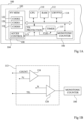
- FIG. 1A represents, schematically and in block form, an electronic device 100 comprising a processing device 102 according to one embodiment of the present description.
- the electronic device 100 is for example an electronic card such as a microcircuit card, hardware for computer use, or a microprocessor or microcontroller circuit.
- the processing device 102 comprises for example a non-volatile memory 104 (NV MEM), for example a flash memory.
- NV MEM non-volatile memory
- the memory 104 includes, for example, an interface access control 108 (ACCES CONTROL) connected to a monotonous counter 106 (MONOTONIC COUNTER).
- ACCES CONTROL interface access control 108
- MONOTONIC COUNTER monotonous counter
- Monotonic counters are known in the state of the art, an example of such a counter being described in the publication " Virtual Monotony Counters and Count-Limited Objects using a TPM without a Trusted OS" by LFG Sarmenta, M. Van Dijk, CW O'Donnell, J. Rhodes and S. Devadas , and in particular in part 3 of this document.
- This document describes meter implementations implemented in hardware and/or software form.
- the monotonic counter 106 is for example implemented in hardware by a digital circuit, such as a personalized integrated circuit (ASIC, from English "Application Specifies Integrated Circuit").
- the monotonic counter is configured to maintain a count value, accessible on an output of the counter.
- the monotonic counter 106 increases its counting value by one or more units but, following each increment, the operation is not reversible. Indeed, the monotonic counter 106 is configured so that its counting value never decreases. In addition, between two increments, the count value is, for example, protected against any decrease. Only the increment command or a modification command allows the replacement of the current value by a new value greater than the current value.
- the monotonic counter 106 is configured so that no command, apart from resetting the processing device 102, makes it possible to return to the previous counting value.
- the monotonic counter 106 again generates a initial count value.
- an initial count value is for example rewritten in the non-volatile storage element of the monotonic counter 106.
- the count value is by example stored in a register (not shown) of the monotonic counter 106.
- the monotonic counter 106 is, in addition, coupled to a protection circuit 113 (TIL PROTECTION).
- the protection circuit 113 implements a watchdog function. Watchdog functions are known in the state of the art and are used, for example, to ensure that a processing circuit does not remain blocked at a particular step of the processing that it performs. In embodiments of the present disclosure, the watchdog function is employed to reduce the risk that the monotonic counter 106 will become stuck at a given count value.
- the protection circuit 113 is for example connected to a counter 115 (TIMER).
- Counter 115 contains a current value incremented by a clock signal CLK.
- the CLK signal is generated for example by a clock generator (not shown) of the device 102, such as a quartz oscillator.
- the processing device 102 further comprises a generic processor 110 (CPU).
- the generic processor 110 is coupled via a bus 116 to the monotonic counter 106 as well as to a RAM (random access memory) 112 and to the non-volatile memory 104.
- the memory 112 and/or the memory 104 stores, for example, instructions for controlling the processor 110.
- the generic processor 110 is further coupled via the bus 116 to a cryptographic processor 114 (CRYPTO).
- the cryptographic processor 114 receives, via the bus 116, encrypted data and returns the decrypted data and/or receives, via bus 116, unencrypted data and returns the encrypted data.
- the non-volatile memory 104 stores for example several start codes, and/or other data, which are associated with several TIL isolation levels (from the English "temporal isolation level").
- Boot codes are for example software and/or firmware codes.
- the non-volatile memory 104 comprises a first zone 118 in which a first start code and/or first data (CODE0) are stored.
- the memory 104 further comprises a second zone 120, in which a second start code and/or second data (CODE1) are stored, as well as a third zone 122 in which a third start code and/or data are stored.
- third data CODE2).
- the first, second and third start codes and/or data are for example associated with three corresponding TIL isolation levels.
- the non-volatile memory 104 may store only two sets of data, or more than three sets of data, in corresponding areas.
- the first, second and third data include first, second and third start codes.
- the TIL isolation level depends on the count value generated by the monotonic counter 106.
- the TIL value is equal to the count value of the monotonic counter 106, although it would be possible to modify the count value in order to generate the TIL value.
- the reading of the first, second and third codes and/or data and/or the execution of the first, second and third start codes are carried out by steps, each step being associated with a corresponding isolation level.
- the access control circuit 108 of the memory 104 is configured so that the reading of these codes/data is controlled according to the isolation level of the step.
- the first data and/or the first code are for example associated with the isolation level, or TIL value, 0 and the access control circuit 108 is configured so that this data and/or code is only accessible for reading when the current TIL counting value is equal to 0.
- the access control circuit 108 locks the zone 118, the first data and/or the first code are then no longer accessible for reading. Following an increment, the current count value changes for example to 1 and the data and/or the start codes associated with isolation level 1, for example the second start code, are executed.
- the access control circuit 108 is configured to allow the reading of one or more data associated with isolation levels greater than that of the current TIL value. For example, in some embodiments, the lower the insulation level, the greater the level of protection. Isolation level 0 is therefore the level providing the most protection, because the corresponding data can only be read when the count value is equal to 0. Thus, each isolation level corresponds to a level of protection of the content of the memory areas associated with it.
- the access control mechanism implemented by circuit 108 can be implemented in several ways.
- circuit 108 when circuit 108 receives a read request associated with one or more addresses in memory 104, it is configured to compare this/these address(es) to the address ranges associated with areas 118, 120, 122 of memory 104. If it is an address in an area associated with a TIL value lower than the current value, circuit 108 is for example configured to block the read operation.
- circuit 108 is configured to deactivate a reading circuit of any zone 118, 120, 122 of memory 104 associated with a TIL value lower than the current value.
- one or more logic gates such as OR gates or AND gates, are coupled into the output path of each area 118, 120 and 122 of memory 104 and also receive an activation signal generated based on of the TIL value allowing each output path to be selectively deactivated.
- the fact that the counting value cannot be decremented during the operating period of the device 100 allows the protection of the start codes once they have been executed, because the access control circuit 108 prevents the reading of the data and/or or the execution of codes associated with TIL isolation levels lower than the current level.
- one or more of the data and/or startup codes and the associated isolation levels are reserved for parameterization phases of the device 102 or for distinct entities in the chain going from the manufacturer to the final user.
- an intermediary entity between the manufacturer of the processing device 102 and the end user of the electronic device 100 may be required to install data and/or startup codes which are specific to the use of the device 100.
- one or more of the most common data and/or startup codes “low”, for example associated with isolation level 0 are for example reserved for the manufacturer of the processing device 102, and other data and/or startup codes are reserved for the intermediate entity.
- the contents of memory areas 118, 120 and 122 include, in certain embodiments, other data in addition to the startup codes of the processing device 102.
- other sensitive data in terms of confidentiality are stored in association with at least one of the first, second and third codes and/or data.
- this other data includes encryption keys used during the execution of the startup codes associated with them.
- memory zones 204, 206 and 208 store sensitive data associated respectively with the start codes 118, 120 and 122 stored in the non-volatile memory 104. Zones 204, 206 and 208 are for example zones distinct from zones 118, 120 and 122, but remain associated with an isolation level corresponding to that of the start codes to which the data is linked.
- This sensitive data includes for example one or more encryption keys stored in each zone 204, 206 and 208 and each of these zones is contained in the non-volatile memory 104.
- each zone 204, 206 and 208 is a subzone of the corresponding zone 118, 120 and 122.
- TIL value is equal to 0
- the attacker would therefore have access to the data and/or codes associated with the value of TIL 0 at any time during the life of the device 100.
- the protection circuit 113 is for example configured to automatically force the value of TIL to be equal to a given value after a predetermined duration after the start of the start-up sequence.
- FIG. 1B schematically represents an embodiment of the protection circuit 113 of the electronic device 100 of the Figure 1A according to one embodiment of the present description.
- the protection circuit 113 includes comparators 124 and 126.
- the comparator 124 receives a signal corresponding to a current value COUNT of the counting value generated by the counter 115 and compares it to a threshold value xT.
- the threshold value xT represents for example a reference duration. This comparison is carried out for example continuously, or at each cycle of the clock, until the COUNT value is greater than or equal to the xT value.
- a comparison by comparator 126 is for example triggered.
- the comparator 126 compares the current TIL value of the monotonic counter 106 with a reference value N.
- the reference value N corresponds to the TIL value which should be current following the reference duration, corresponding to xT, after the start of 'a startup sequence.
- the comparator 126 transmits a signal to the monotonic counter 106 triggering, for example, one or more increments of the monotonic counter 106, in order to that the value of TIL becomes equal to at least the value of reference N.
- the reference value N is then transmitted to the access control circuit 108, which has the consequence of prohibiting access to memory data associated with TIL values lower than N.
- the comparator 126 sends the reference value N to the monotonic counter 106 in order to force the change of the value of TIL towards this reference value N.
- the monotonic counter 106 is for example configured to prohibit the overwriting of its current value by a lower value.
- FIG 2 represents an example of the data and codes accessible during a secure startup of the processing device 102 of the Figure 1A according to one embodiment of the present description.
- the current count value is for example equal to 0.
- an isolation level 0 is associated with a first code (CODE0) as well as with first sensitive data (KEY0).
- the access control circuit 108 is configured, for example, so that this first code and these first data are exclusively accessible when the current count value is equal to 0.
- the control circuit access authorizes for example access to all memory areas 204, 206 and 208, as well as to all areas 118, 120 and 122. Indeed, in certain cases, in order for example to anticipate subsequent steps in the startup process, one or more of the other startup codes CODE1, CODE2 are accessible for reading during step 200.
- the generic processor 110 commands a first increment of the current count value by the monotonic counter 106.
- the first code includes a command requesting the increment of the counter. This command is for example transmitted to a control register (not illustrated) of the monotonic counter 106.
- the current count value of the monotonic counter 106 is for example equal to 1, corresponding to the second step 201 of startup.
- the access control circuit 108 receives the new current count value, and is configured to prevent, on the basis of this count value greater than 0, any access to the first code as well as to the first data which is associated with the level isolation 0. In other words, memory areas 118 and 204 are locked on the basis of any count value strictly greater than 0.
- Insulation level 1 is associated with a second code (CODE1) contained in zone 120 as well as with second data (KEY1) contained in zone 202.
- CODE2 for example example associated with insulation level 2 and contained in zone 122, is accessible for reading on the basis of the current count value equal to 1.
- the generic processor 110 commands a second increment of the current count value by the monotonic counter 106. For example, after this second increment, the current count value of the counter monotone 106 is equal to 2, corresponding to the third step 203 of startup. Isolation level 2 is associated with the third code (CODE2) as well as third data (KEY2).
- the access control circuit 108 receives the new count value, and is configured to prevent, based on this count value greater than 1, any access to the first and second codes as well as to the first and second data which are associated with isolation levels less than or equal to 1.
- the generic processor 110 when the last start code is executed, for example the third start code, commands a third increment of the current count value by the monotonic counter 106.
- the access control circuit 108 then locks all access to the first, second and third start codes as well as the first, second and third data.
- the current count value is not incremented by the monotonic counter 106 and access to the third start code as well as 'to the third data remains authorized by the access control circuit.
- FIG. 3 is a flowchart representing the operations of a secure startup method of the processing device 102 according to an exemplary embodiment of the present description according to the invention.
- a step 300 (LAUNCH BOOT SEQUENCE AT TIL0 AND START COUNT), the device 102 is reset and a startup sequence begins.
- the monotonic counter 106 then generates a first value of TIL, for example equal to 0.
- the counter 115 is initialized and a current value COUNT of the counter 115 is incremented at each cycle of the clock of the device 102.
- the protection circuit 113 is configured to trigger the increment of the value of TIL to the value M, a duration x1 after the start of the sequence starting.
- this operation 301 includes the configuration of a reference value M and a threshold value x1 in a register. In other embodiments, these values are invariable and stored in a non-volatile manner in a memory of the device 100.
- the protection circuit 113 can also be configured to trigger the increment of the value of TIL to the value N, a duration x2 after the start of the sequence starting.
- this operation 302 includes for example the configuration of a reference value N and a threshold value x2 in a register. In other embodiments, these values are invariable and stored in a non-volatile manner in a memory of the device 100.
- the protection methods on the basis of one or more durations xT are for example implemented in parallel, the Figure 3 illustrating an example of a first method 303 based on duration x1, and a second method 303' based on duration x2.
- the method 303 comprises steps 304 to 306.
- a step 304 (COUNT ⁇ x1?), the comparator 124 of the protection circuit 113 compares the current value COUNT of the counter 115 with the value x1. If the COUNT value is strictly less than the value x1 (branch Y), the process resumes in this same step 304. If the COUNT value is greater than or equal to the value x1 (branch N), the comparator 126 compares the value of TIL current of the monotonic counter 106 with the value M (block 305, TIL ⁇ M). If the current TIL value is greater than or equal to the value M, the process ends in step 307 (END). In the case where the current TIL value is strictly less than the value M, the TIL value is forced to the value M in an operation 306.
- step 307 the process ends in step 307 (END).
- the protection circuit 113 is then only configured to automatically trigger the increment of the TIL value to the value 2.5 microseconds after the start of the startup sequence. In the case where the value of TIL is already equal to 2, the protection circuit 113 is for example deactivated.
- the method 303' comprises operations 304', 305' and 306' similar to operations 304, 305 and 306, except that the threshold value x1 is replaced by the threshold value x2 in operation 304', and the reference value M is replaced by the reference value N in operations 305' and 306'.
- the comparisons made in operations 304' and 305' are for example implemented by another circuit similar to that of the Figure 1B .
- the protection circuit is then configured to automatically trigger the increment of the value of TIL to the value 2, for example 5 microseconds after the start of the startup sequence, and in parallel to automatically trigger the increment of the TIL value to value 3, for example 10 microseconds after the start of the startup sequence.
- the protection circuit 113 is for example deactivated when the current TIL value is equal to 3.
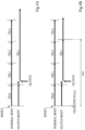
- FIGS. 4A to 4D are timing diagrams illustrating an example of the progress of a secure startup of the processing device 102.
- FIGS. 4A to 4D each represent two time lines representing the progress of a startup from the initialization (RESET) of the device 102.
- the upper line (NORMAL BOOT) of the Figures 4A to 4D corresponds to the launch of a startup sequence in the absence of a glitch attack.
- the initial value of TIL is 0, and this value is incremented three times during the startup sequence.
- the bottom line of the Figure 4A represents an example of starting the device 102 undergoing a “glitch” attack (GLITCH) when the TIL value is equal to 1.
- GLITCH a “glitch” attack
- the increment (+) of the TIL values is no longer applied after the arrival of the “glitch”, and the TIL value therefore remains frozen at 1.
- the startup sequence is then carried out while keeping the TIL value 1.
- the attacker then has access to the data associated with the value of TIL 1 even when the startup sequence is finished.
- the bottom line of the Figure 4B represents an example of starting the device 100 illustrating one mode of implementation of the method described.
- the protection circuit 113 is configured (TILPROTECT(3,x)) to force the value of TIL to be equal to 3 following a duration of x microseconds after the start of the startup sequence.
- a glitch attack occurs when the TIL value is 1.
- the startup sequence continues and the TIL value is not incremented to the value 2.
- a duration of x microseconds after the start of the startup sequence the protection circuit 113 forces the TIL value to be equal to the value 3.
- the data and/or codes associated with the TIL values 1 and 2 are then no longer accessible by the attacker.
- the bottom line of the Figure 4C represents an example of starting the processing device 102 similar to that of the Figure 4B .
- the protection circuit 113 is configured in the same way as in Figure 4B .
- a “glitch” attack (GLITCH) is carried out when the TIL value is still 0.
- the TIL values 1 and 2 are not protected, the startup sequence continues, while keeping the TIL value 0.
- a duration x microsecond after the start of the startup sequence the protection circuit 113 forces the TIL value to be equal to 3.
- the data and/or codes associated with the TIL values 0, 1 and 2 are then no longer accessible by attacking him.
- the bottom line of the figure 4D represents an example of starting the processing device 102 for which the protection circuit 113 is configured (TILPROTECT (1,y)) to force the value of TIL to be equal to 1 following a duration of y microseconds after the start of the startup sequence.
- TILPROTECT (1,y) a “glitch” attack
- GLITCH a “glitch” attack
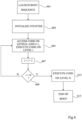
- FIG. 5 is a flowchart representing the operations of a secure startup method of a processing device 102 according to an exemplary embodiment of the present description not covered by the invention. This method is implemented for example by the generic processor 110, the monotonic counter 106 and the access control circuit 108, of the processing device 102 of the Figure 1A .
- a step 501 the processing device 102 starts.
- this is the first start of the device 102 after its production.
- this involves a start-up carried out by an intermediate entity between the manufacturer of the device 102 and its end user.
- this involves a so-called start of operation of the electronic device 100 carried out by the end user.
- step 503 subsequent to step 501, the monotonic counter 106 is initialized to an initial value, being a natural integer.
- each power-up of the processing device 102 causes the initialization of the count value, for example to 0 or 1.
- each powering up of the processing device 102 causes the current count value to be replaced by the initial count value, for example equal to 0 or 1.
- the initial count value generated following a power-up may vary depending on the state, or context, of the processing device 102.
- one or more count values correspond to one or more levels of isolation reserved for an initial parameterization phase of the device 102, including for example the installation of firmware.
- the data and/or codes associated with these isolation levels are for example used for this initial parameterization.
- the processing device 102 has the context "blank" and the initial count value is equal to a value reserved for parameterization, such as 0.
- the context of the device becomes for example "parameterization completed".
- powering up the device 102 carried out for example by an intermediate entity between the manufacturer and the end user and/or by the end user, will then trigger a count value greater than the reserved count value , and for example equal to 1.
- the start code(s), as well as the sensitive data, associated with the isolation level corresponding to the reserved counting value will, therefore, be inaccessible.
- the context of the device is detected by the presence of a voltage on a start pin of the device, this voltage being applied for example by adding a jumper between the start pin and another pin to a supply voltage.
- the context of the device is detected by the value of one or more bits stored in a non-volatile manner, and in a protected manner, in memory 104, or in another memory.
- the generic processor 110 is arranged to detect the context of the device 102 when powering up the device 102, and to configure the initial count value of the monotonic counter 106 accordingly.
- the monotonic counter 106 is arranged to itself detect the context of the device 102 and to itself configure its initial counting value, when powering up the device 102.
- a step 505 (READ AND EXECUTE CODE ON LEVEL i)
- the data and the start codes associated with the isolation level i are read by the generic processor 110 and the start codes associated with the level isolation i are executed.
- N is equal to 2.
- step 509 the generic processor 110 triggers the increment of the count value .
- the count value changes from i to i+1. It is also possible that the increment increases the count value by several units. The process then resumes at step 505.
- the process ends in a step 511 (END OF BOOT) in which the startup of the processing device 102 ends.
- the current count value remains equal to N following step 511.
- the count value is incremented during step 511, and the current count value becomes equal at N+1.
- the access control circuit is then configured to prevent access to all start codes based on this count value.
- FIG. 6 is a flowchart representing the operations of a secure startup method of a processing device 102 according to another embodiment of the present description not covered by the invention. This method is implemented for example by the generic processor 110, the monotonic counter 106 and the access control circuit 108, of the processing device 102 of the Figure 1A .
- Steps 601 and 603 are similar to steps 501 and 503 of the figure 5 , and will not be described again in detail.
- step 605 (ACCESS CODE ON LEVELS i AND i+1, EXECUTE CODE ON LEVEL i)
- step 603 the data and startup codes associated with the isolation levels i+1 are accessible by the processor generic 110 and the startup code(s) associated with the isolation level i are executed.
- the data or codes associated with isolation level i contain one or more encryption keys, encrypted or not, which will be used during the execution of one or more codes associated with isolation level i+1 .
- write access is for example authorized on the memory area(s) associated with isolation level i+1 in order to provision the keys to the codes associated with isolation level i+1.
- the codes associated with isolation level i contain instructions aimed at verifying the integrity of the data and/or codes associated with isolation level i+1. Thus, read access to the memory zone(s) associated with isolation level i+1 is authorized in order to carry out this verification.
- step 607 subsequent to step 605, the count value is incremented. For example the count value goes from i to i+1. In other examples, the increment increases i by several units.
- the start of the processing device 102 ends with a step 615 (END OF BOOT), which is similar to step 511 of the figure 5 , and is not described again in detail.
- the process whose implementation is presented by the Figure 6 allows delayed start codes to be read.
- the start codes associated with an insulation level are read when the counting value is lower than the level value. This allows a saving of time compared to the implementation of the process presented in the figure 5 .
- An advantage of the embodiments described is that startup codes, as well as sensitive data in terms of confidentiality, are significantly protected against attacks, and in particular “glitch” attacks, by the use of a counter monotonic and a protection circuit as described in the present description.
- Another advantage of the embodiments described is that the protection mechanisms of a startup sequence are provided by hardware circuits.
Landscapes
- Engineering & Computer Science (AREA)
- Software Systems (AREA)
- Theoretical Computer Science (AREA)
- General Engineering & Computer Science (AREA)
- Computer Hardware Design (AREA)
- Computer Security & Cryptography (AREA)
- Physics & Mathematics (AREA)
- General Physics & Mathematics (AREA)
- Storage Device Security (AREA)
- Emergency Protection Circuit Devices (AREA)
- Compression, Expansion, Code Conversion, And Decoders (AREA)
Claims (15)
- Verfahren, das Folgendes aufweist:- den Schutz einer Startsequenz eines Verarbeitungsgeräts (102) durch Anheben eines Zählerwerts (TIL), der durch einen gleichbleibenden Zähler (106) erzeugt wird;- einen erster Zeitabschnitt (x) nach dem Beginn der Startsequenz (RESET), den Vergleich, durch die Schutzschaltung (113), zwischen dem Zählerwert und einem ersten Referenzwert (M); und- falls der Zählerwert kleiner ist, als der erste Referenzwert, die Änderung, durch die Schutzschaltung (113), des Zählerwerts zu dem ersten Referenzwert.
- Verfahren nach Anspruch 1, wobei der Zählerwert (TIL) in einem Register des gleichbleibenden Zählers (106) gespeichert wird, wobei die Änderung des Zählerwerts zu dem ersten Referenzwert (M) Überschreiben des Zählerwerts mit dem ersten Referenzwert in das Register aufweist.
- Verfahren nach Anspruch 1 oder 2, das ferner den Vergleich aufweist, und zwar durch die Schutzschaltung (113), zwischen einem momentanen Wert (COUNT) eines Hardwarezählers (115), der durch einen Referenztakt eingestuft wird, und einem Schwellenwert (xT, x1) um zu bestimmen ob der erste Zeitabschnitt (x) erreicht wurde.
- Verfahren nach einem der Ansprüche 1 bis 3, das ferner das Deaktivieren der Schutzschaltung (113) aufweist, wenn der erste Zeitabschnitt (x) erreicht wurde.
- Verfahren nach einem der Ansprüche 1 bis 4, das Folgendes aufweist:- nach einem zweiten Zeitabschnitt (y), den Vergleich, und zwar durch die Schutzschaltung (113), zwischen dem Zählerwert (TIL) und einem zweiten Referenzwert (x2); und- falls der Zählerwert kleiner ist, als der zweite Referenzwert (N), die Änderung, und zwar durch die Schutzschaltung (113), des Zählerwerts zu dem zweiten Referenzwert (N).
- Verfahren nach einem der Ansprüche 1 bis 5, das ferner das Erzeugen des Zählerwerts (TIL) aufweist, und zwar durch den gleichbleibenden Zähler (106) während einer ersten Phase der Startsequenz.
- Verfahren nach einem der Ansprüche 1 bis 6, das Folgendes aufweist:- die Übertragung, und zwar durch den gleichbleibenden Zähler (106), des Zählerwerts (TIL) an eine Schaltung zum Steuern des Zugriffs (108) auf einen Speicher (104); und- das Lesen, und zwar auf der Basis des Zählerwerts, von ersten Daten (118), die in dem Speicher gespeichert sind.
- Verfahren nach Anspruch 7, wobei das Lesen der ersten Daten (118) verboten wird, und zwar durch die Zugriffssteuerschaltung (108) auf der Basis des ersten Referenzwerts (M).
- Verfahren nach Anspruch 7 oder 8, wobei die ersten Daten (118) erste Start-Codes aufweisen.
- Verfahren nach einem der Ansprüche 7 bis 9, das ferner das Lesen aufweist, und zwar auf der Basis des Zählerwerts (TIL), von zweiten Daten, die in dem Speicher (120, 122) gespeichert sind.
- Verarbeitungsgerät (102), das Folgendes aufweist:- einen gleichbleibenden Zähler (106), der eingerichtet ist eine Startsequenz des Geräts zu schützen, und zwar durch Anheben eines Zählerwerts (TIL); und- eine Schutzschaltung (113), die eingerichtet ist zum:- einen ersten Zeitabschnitt (x, y) nach dem Beginn der Startsequenz, Vergleichen, zwischen dem Zählerwert und einem ersten Referenzwert (M, N); und- falls der Zählerwert kleiner ist, als der erste Referenzwert, Ändern des Zählerwerts zu dem ersten Referenzwert.
- Verarbeitungsgerät (102) nach Anspruch 11, wobei die Schutzschaltung (113) ferner eingerichtet ist zum Vergleichen zwischen einem momentanen Wert (COUNT) eines Hardwarezählers (115), der durch einen Referenztakt eingestuft wird, und einem ersten Schwellenwert (xT, x1, x2) um zu bestimmen ob der erste Zeitabschnitt (x, y) erreicht wurde.
- Verarbeitungsgerät (102) nach Anspruch 11 oder 12, wobei die Schutzschaltung (113) eingerichtet ist, deaktiviert zu werden, wenn der ersten Zeitabschnitt (x, y) erreicht ist.
- Verarbeitungsgerät (102) nach einem der Ansprüche 11 bis 13, wobei:- der gleichbleibende Zähler (106) eingerichtet ist den Zählerwert (TIL) zu übertragen, und zwar an eine Schaltung zum Steuern des Zugriffs (108) auf einen Speicher (104), wobei die Zugriffssteuerschaltung eingerichtet ist zum:- Autorisieren des Lesens, und zwar auf der Basis des Zählerwerts, von ersten Daten (118), die in dem Speicher gespeichert sind; und- nicht Autorisieren des Lesens der ersten Daten auf der Basis des ersten Referenzwerts (M, N).
- Verarbeitungsgerät (102) nach Anspruch 14, wobei die Zugriffssteuerschaltung (108) ferner eingerichtet ist zum Autorisieren des Lesens von zweiten Daten (120, 122) auf der Basis des Zählerwerts (TIL).
Applications Claiming Priority (1)
| Application Number | Priority Date | Filing Date | Title |
|---|---|---|---|
| FR2108928A FR3126572B1 (fr) | 2021-08-26 | 2021-08-26 | Démarrage sécurisé d’une unité de traitement |
Publications (2)
| Publication Number | Publication Date |
|---|---|
| EP4145704A1 EP4145704A1 (de) | 2023-03-08 |
| EP4145704B1 true EP4145704B1 (de) | 2024-02-07 |
Family
ID=79269633
Family Applications (1)
| Application Number | Title | Priority Date | Filing Date |
|---|---|---|---|
| EP22191050.8A Active EP4145704B1 (de) | 2021-08-26 | 2022-08-18 | Gesichertes starten einer verarbeitungseinheit |
Country Status (4)
| Country | Link |
|---|---|
| US (1) | US11934529B2 (de) |
| EP (1) | EP4145704B1 (de) |
| CN (1) | CN115935443A (de) |
| FR (1) | FR3126572B1 (de) |
Family Cites Families (12)
| Publication number | Priority date | Publication date | Assignee | Title |
|---|---|---|---|---|
| US8332653B2 (en) | 2004-10-22 | 2012-12-11 | Broadcom Corporation | Secure processing environment |
| US20060198515A1 (en) * | 2005-03-03 | 2006-09-07 | Seagate Technology Llc | Secure disc drive electronics implementation |
| US8184812B2 (en) | 2009-06-03 | 2012-05-22 | Freescale Semiconductor, Inc. | Secure computing device with monotonic counter and method therefor |
| EP2449499B1 (de) * | 2009-07-01 | 2014-11-26 | Panasonic Corporation | Sicheres startverfahren und sichere startvorrichtung |
| EP2503482A1 (de) * | 2011-03-23 | 2012-09-26 | ST-Ericsson SA | Elektronische Vorrichtung mit Flash-Speicherkomponente |
| US10659054B2 (en) | 2018-02-23 | 2020-05-19 | Nxp B.V. | Trusted monotonic counter using internal and external non-volatile memory |
| US10719607B2 (en) | 2018-03-19 | 2020-07-21 | Nxp B.V. | Data integrity verification in a non-volatile memory |
| GB201809526D0 (en) | 2018-06-11 | 2018-07-25 | Wibu Systems Ltd | Key protection device |
| US10868679B1 (en) | 2019-07-25 | 2020-12-15 | Cypress Semiconductor Corporation | Nonvolatile memory device with regions having separately programmable secure access features and related methods and systems |
| EP3933630A1 (de) * | 2020-06-30 | 2022-01-05 | Nxp B.V. | Verfahren und vorrichtung zur anpassung von systemsicherheitsrichtlinien auf basis des systemzustands |
| US11784827B2 (en) | 2021-03-09 | 2023-10-10 | Micron Technology, Inc. | In-memory signing of messages with a personal identifier |
| FR3121526A1 (fr) | 2021-03-31 | 2022-10-07 | STMicroelectronics (Alps) SAS | Démarrage sécurisé d’une unité de traitement |
-
2021
- 2021-08-26 FR FR2108928A patent/FR3126572B1/fr active Active
-
2022
- 2022-08-18 EP EP22191050.8A patent/EP4145704B1/de active Active
- 2022-08-25 US US17/822,272 patent/US11934529B2/en active Active
- 2022-08-26 CN CN202211037309.9A patent/CN115935443A/zh active Pending
Also Published As
| Publication number | Publication date |
|---|---|
| US20230069651A1 (en) | 2023-03-02 |
| US11934529B2 (en) | 2024-03-19 |
| FR3126572B1 (fr) | 2023-08-25 |
| CN115935443A (zh) | 2023-04-07 |
| FR3126572A1 (fr) | 2023-03-03 |
| EP4145704A1 (de) | 2023-03-08 |
Similar Documents
| Publication | Publication Date | Title |
|---|---|---|
| US10762210B2 (en) | Firmware protection and validation | |
| EP0826169B1 (de) | Verbesserte integrierte schaltung und verfahren zur verwendung dieser schaltung | |
| EP1605333B1 (de) | Programmausführungssteuerung | |
| EP4068128A1 (de) | Gesichertes starten einer verarbeitungseinheit | |
| WO2005101160A1 (fr) | Procede et dispositif pour controler l’acces a un periferique | |
| EP3633495B1 (de) | Verfahren zur verwaltung einer dvfs-stromversorgung, und entsprechendes system | |
| FR2948795A1 (fr) | Detecteur d'injection de fautes dans un circuit integre | |
| EP1943604A1 (de) | Halbleiteranordnung und verfahren zum verhindern von attacken auf die halbleiteranordnung | |
| FR3072195A1 (fr) | Procede de gestion d'un retour de produit pour analyse et produit correspondant | |
| EP1220101B1 (de) | Verfahren und Vorrichtung zum Schutz gegen unbefugte Benutzung eines integrierten Schaltkreises | |
| EP4145704B1 (de) | Gesichertes starten einer verarbeitungseinheit | |
| US20190123900A1 (en) | Rekeying keys for encrypted data in nonvolatile memories | |
| EP3441902B1 (de) | Schutzverfahren einer elektronischen vorrichtung gegen angriffe durch fehlerinjektion | |
| EP1633074A1 (de) | Integrierte Schaltung mit kodiertem Sicherungsignal, Sicherungsverfahren, Vorrichtung und mittels eines entsprechenden dynamischen Schlüssels kodiertes Sicherungsignal | |
| EP4068134A1 (de) | Gesicherte fehlerbeseitigung | |
| EP3042334B1 (de) | Verfahren zur installation einer sicherheitsvorrichtung in abhängigkeit einen vertrauensindex in einer elektronischen vorrichtung mit speicher und vorrichtung zur durchführung des verfahrens | |
| FR2752992A1 (fr) | Dispositif de protection de donnees memorisees | |
| WO2023117270A1 (fr) | Module et procédé de sécurisation d'un équipement informatique | |
| EP2955661B1 (de) | Schutz von in einem flüchtigen Speicher gespeicherten Daten | |
| FR3121530A1 (fr) | Procédé et dispositif pour le déchiffrement sécurisé de données chiffrées | |
| FR2752993A1 (fr) | Dispositif de protection de donnees memorisees utilisant un circuit de temporisation | |
| EP2630605B1 (de) | Verfahren zur sicherung der ausführung eines computercodes mittels dynamischer redundanz | |
| EP4078418A1 (de) | Elektronisches system und verfahren zur dynamischen aktivierung von gegenmassnahmen | |
| EP4068680A1 (de) | Sichere aufbewahrung von verschlüsselungsschlüsseln | |
| FR3123468A1 (fr) | Système sur puce |
Legal Events
| Date | Code | Title | Description |
|---|---|---|---|
| PUAI | Public reference made under article 153(3) epc to a published international application that has entered the european phase |
Free format text: ORIGINAL CODE: 0009012 |
|
| STAA | Information on the status of an ep patent application or granted ep patent |
Free format text: STATUS: REQUEST FOR EXAMINATION WAS MADE |
|
| 17P | Request for examination filed |
Effective date: 20220818 |
|
| AK | Designated contracting states |
Kind code of ref document: A1 Designated state(s): AL AT BE BG CH CY CZ DE DK EE ES FI FR GB GR HR HU IE IS IT LI LT LU LV MC MK MT NL NO PL PT RO RS SE SI SK SM TR |
|
| GRAP | Despatch of communication of intention to grant a patent |
Free format text: ORIGINAL CODE: EPIDOSNIGR1 |
|
| STAA | Information on the status of an ep patent application or granted ep patent |
Free format text: STATUS: GRANT OF PATENT IS INTENDED |
|
| INTG | Intention to grant announced |
Effective date: 20230905 |
|
| GRAS | Grant fee paid |
Free format text: ORIGINAL CODE: EPIDOSNIGR3 |
|
| GRAA | (expected) grant |
Free format text: ORIGINAL CODE: 0009210 |
|
| STAA | Information on the status of an ep patent application or granted ep patent |
Free format text: STATUS: THE PATENT HAS BEEN GRANTED |
|
| AK | Designated contracting states |
Kind code of ref document: B1 Designated state(s): AL AT BE BG CH CY CZ DE DK EE ES FI FR GB GR HR HU IE IS IT LI LT LU LV MC MK MT NL NO PL PT RO RS SE SI SK SM TR |
|
| REG | Reference to a national code |
Ref country code: GB Ref legal event code: FG4D Free format text: NOT ENGLISH |
|
| REG | Reference to a national code |
Ref country code: CH Ref legal event code: EP |
|
| REG | Reference to a national code |
Ref country code: DE Ref legal event code: R096 Ref document number: 602022001862 Country of ref document: DE |
|
| REG | Reference to a national code |
Ref country code: IE Ref legal event code: FG4D Free format text: LANGUAGE OF EP DOCUMENT: FRENCH |
|
| REG | Reference to a national code |
Ref country code: LT Ref legal event code: MG9D |
|
| REG | Reference to a national code |
Ref country code: NL Ref legal event code: MP Effective date: 20240207 |
|
| PG25 | Lapsed in a contracting state [announced via postgrant information from national office to epo] |
Ref country code: IS Free format text: LAPSE BECAUSE OF FAILURE TO SUBMIT A TRANSLATION OF THE DESCRIPTION OR TO PAY THE FEE WITHIN THE PRESCRIBED TIME-LIMIT Effective date: 20240607 |
|
| PG25 | Lapsed in a contracting state [announced via postgrant information from national office to epo] |
Ref country code: LT Free format text: LAPSE BECAUSE OF FAILURE TO SUBMIT A TRANSLATION OF THE DESCRIPTION OR TO PAY THE FEE WITHIN THE PRESCRIBED TIME-LIMIT Effective date: 20240207 |
|
| PG25 | Lapsed in a contracting state [announced via postgrant information from national office to epo] |
Ref country code: GR Free format text: LAPSE BECAUSE OF FAILURE TO SUBMIT A TRANSLATION OF THE DESCRIPTION OR TO PAY THE FEE WITHIN THE PRESCRIBED TIME-LIMIT Effective date: 20240508 |
|
| REG | Reference to a national code |
Ref country code: AT Ref legal event code: MK05 Ref document number: 1656012 Country of ref document: AT Kind code of ref document: T Effective date: 20240207 |
|
| PG25 | Lapsed in a contracting state [announced via postgrant information from national office to epo] |
Ref country code: HR Free format text: LAPSE BECAUSE OF FAILURE TO SUBMIT A TRANSLATION OF THE DESCRIPTION OR TO PAY THE FEE WITHIN THE PRESCRIBED TIME-LIMIT Effective date: 20240207 Ref country code: NL Free format text: LAPSE BECAUSE OF FAILURE TO SUBMIT A TRANSLATION OF THE DESCRIPTION OR TO PAY THE FEE WITHIN THE PRESCRIBED TIME-LIMIT Effective date: 20240207 Ref country code: RS Free format text: LAPSE BECAUSE OF FAILURE TO SUBMIT A TRANSLATION OF THE DESCRIPTION OR TO PAY THE FEE WITHIN THE PRESCRIBED TIME-LIMIT Effective date: 20240507 |
|
| PG25 | Lapsed in a contracting state [announced via postgrant information from national office to epo] |
Ref country code: ES Free format text: LAPSE BECAUSE OF FAILURE TO SUBMIT A TRANSLATION OF THE DESCRIPTION OR TO PAY THE FEE WITHIN THE PRESCRIBED TIME-LIMIT Effective date: 20240207 |
|
| PG25 | Lapsed in a contracting state [announced via postgrant information from national office to epo] |
Ref country code: AT Free format text: LAPSE BECAUSE OF FAILURE TO SUBMIT A TRANSLATION OF THE DESCRIPTION OR TO PAY THE FEE WITHIN THE PRESCRIBED TIME-LIMIT Effective date: 20240207 |
|
| PG25 | Lapsed in a contracting state [announced via postgrant information from national office to epo] |
Ref country code: RS Free format text: LAPSE BECAUSE OF FAILURE TO SUBMIT A TRANSLATION OF THE DESCRIPTION OR TO PAY THE FEE WITHIN THE PRESCRIBED TIME-LIMIT Effective date: 20240507 Ref country code: NO Free format text: LAPSE BECAUSE OF FAILURE TO SUBMIT A TRANSLATION OF THE DESCRIPTION OR TO PAY THE FEE WITHIN THE PRESCRIBED TIME-LIMIT Effective date: 20240507 Ref country code: NL Free format text: LAPSE BECAUSE OF FAILURE TO SUBMIT A TRANSLATION OF THE DESCRIPTION OR TO PAY THE FEE WITHIN THE PRESCRIBED TIME-LIMIT Effective date: 20240207 Ref country code: LT Free format text: LAPSE BECAUSE OF FAILURE TO SUBMIT A TRANSLATION OF THE DESCRIPTION OR TO PAY THE FEE WITHIN THE PRESCRIBED TIME-LIMIT Effective date: 20240207 Ref country code: IS Free format text: LAPSE BECAUSE OF FAILURE TO SUBMIT A TRANSLATION OF THE DESCRIPTION OR TO PAY THE FEE WITHIN THE PRESCRIBED TIME-LIMIT Effective date: 20240607 Ref country code: HR Free format text: LAPSE BECAUSE OF FAILURE TO SUBMIT A TRANSLATION OF THE DESCRIPTION OR TO PAY THE FEE WITHIN THE PRESCRIBED TIME-LIMIT Effective date: 20240207 Ref country code: GR Free format text: LAPSE BECAUSE OF FAILURE TO SUBMIT A TRANSLATION OF THE DESCRIPTION OR TO PAY THE FEE WITHIN THE PRESCRIBED TIME-LIMIT Effective date: 20240508 Ref country code: FI Free format text: LAPSE BECAUSE OF FAILURE TO SUBMIT A TRANSLATION OF THE DESCRIPTION OR TO PAY THE FEE WITHIN THE PRESCRIBED TIME-LIMIT Effective date: 20240207 Ref country code: ES Free format text: LAPSE BECAUSE OF FAILURE TO SUBMIT A TRANSLATION OF THE DESCRIPTION OR TO PAY THE FEE WITHIN THE PRESCRIBED TIME-LIMIT Effective date: 20240207 Ref country code: BG Free format text: LAPSE BECAUSE OF FAILURE TO SUBMIT A TRANSLATION OF THE DESCRIPTION OR TO PAY THE FEE WITHIN THE PRESCRIBED TIME-LIMIT Effective date: 20240207 Ref country code: AT Free format text: LAPSE BECAUSE OF FAILURE TO SUBMIT A TRANSLATION OF THE DESCRIPTION OR TO PAY THE FEE WITHIN THE PRESCRIBED TIME-LIMIT Effective date: 20240207 |
|
| PG25 | Lapsed in a contracting state [announced via postgrant information from national office to epo] |
Ref country code: PT Free format text: LAPSE BECAUSE OF FAILURE TO SUBMIT A TRANSLATION OF THE DESCRIPTION OR TO PAY THE FEE WITHIN THE PRESCRIBED TIME-LIMIT Effective date: 20240607 Ref country code: PL Free format text: LAPSE BECAUSE OF FAILURE TO SUBMIT A TRANSLATION OF THE DESCRIPTION OR TO PAY THE FEE WITHIN THE PRESCRIBED TIME-LIMIT Effective date: 20240207 |
|
| PG25 | Lapsed in a contracting state [announced via postgrant information from national office to epo] |
Ref country code: SE Free format text: LAPSE BECAUSE OF FAILURE TO SUBMIT A TRANSLATION OF THE DESCRIPTION OR TO PAY THE FEE WITHIN THE PRESCRIBED TIME-LIMIT Effective date: 20240207 Ref country code: PT Free format text: LAPSE BECAUSE OF FAILURE TO SUBMIT A TRANSLATION OF THE DESCRIPTION OR TO PAY THE FEE WITHIN THE PRESCRIBED TIME-LIMIT Effective date: 20240607 Ref country code: PL Free format text: LAPSE BECAUSE OF FAILURE TO SUBMIT A TRANSLATION OF THE DESCRIPTION OR TO PAY THE FEE WITHIN THE PRESCRIBED TIME-LIMIT Effective date: 20240207 Ref country code: LV Free format text: LAPSE BECAUSE OF FAILURE TO SUBMIT A TRANSLATION OF THE DESCRIPTION OR TO PAY THE FEE WITHIN THE PRESCRIBED TIME-LIMIT Effective date: 20240207 |
|
| PGFP | Annual fee paid to national office [announced via postgrant information from national office to epo] |
Ref country code: DE Payment date: 20240723 Year of fee payment: 3 |
|
| PG25 | Lapsed in a contracting state [announced via postgrant information from national office to epo] |
Ref country code: DK Free format text: LAPSE BECAUSE OF FAILURE TO SUBMIT A TRANSLATION OF THE DESCRIPTION OR TO PAY THE FEE WITHIN THE PRESCRIBED TIME-LIMIT Effective date: 20240207 |
|
| PG25 | Lapsed in a contracting state [announced via postgrant information from national office to epo] |
Ref country code: SM Free format text: LAPSE BECAUSE OF FAILURE TO SUBMIT A TRANSLATION OF THE DESCRIPTION OR TO PAY THE FEE WITHIN THE PRESCRIBED TIME-LIMIT Effective date: 20240207 |