EP4145595B1 - Battery pack and vehicle comprising battery pack - Google Patents
Battery pack and vehicle comprising battery pack Download PDFInfo
- Publication number
- EP4145595B1 EP4145595B1 EP21903746.2A EP21903746A EP4145595B1 EP 4145595 B1 EP4145595 B1 EP 4145595B1 EP 21903746 A EP21903746 A EP 21903746A EP 4145595 B1 EP4145595 B1 EP 4145595B1
- Authority
- EP
- European Patent Office
- Prior art keywords
- pipe
- sealing unit
- pack
- pack case
- battery
- Prior art date
- Legal status (The legal status is an assumption and is not a legal conclusion. Google has not performed a legal analysis and makes no representation as to the accuracy of the status listed.)
- Active
Links
Images




Classifications
-
- H—ELECTRICITY
- H01—ELECTRIC ELEMENTS
- H01M—PROCESSES OR MEANS, e.g. BATTERIES, FOR THE DIRECT CONVERSION OF CHEMICAL ENERGY INTO ELECTRICAL ENERGY
- H01M10/00—Secondary cells; Manufacture thereof
- H01M10/60—Heating or cooling; Temperature control
- H01M10/65—Means for temperature control structurally associated with the cells
- H01M10/655—Solid structures for heat exchange or heat conduction
- H01M10/6556—Solid parts with flow channel passages or pipes for heat exchange
-
- H—ELECTRICITY
- H01—ELECTRIC ELEMENTS
- H01M—PROCESSES OR MEANS, e.g. BATTERIES, FOR THE DIRECT CONVERSION OF CHEMICAL ENERGY INTO ELECTRICAL ENERGY
- H01M10/00—Secondary cells; Manufacture thereof
- H01M10/60—Heating or cooling; Temperature control
- H01M10/61—Types of temperature control
- H01M10/613—Cooling or keeping cold
-
- H—ELECTRICITY
- H01—ELECTRIC ELEMENTS
- H01M—PROCESSES OR MEANS, e.g. BATTERIES, FOR THE DIRECT CONVERSION OF CHEMICAL ENERGY INTO ELECTRICAL ENERGY
- H01M10/00—Secondary cells; Manufacture thereof
- H01M10/60—Heating or cooling; Temperature control
- H01M10/62—Heating or cooling; Temperature control specially adapted for specific applications
- H01M10/625—Vehicles
-
- H—ELECTRICITY
- H01—ELECTRIC ELEMENTS
- H01M—PROCESSES OR MEANS, e.g. BATTERIES, FOR THE DIRECT CONVERSION OF CHEMICAL ENERGY INTO ELECTRICAL ENERGY
- H01M10/00—Secondary cells; Manufacture thereof
- H01M10/60—Heating or cooling; Temperature control
- H01M10/65—Means for temperature control structurally associated with the cells
- H01M10/656—Means for temperature control structurally associated with the cells characterised by the type of heat-exchange fluid
- H01M10/6567—Liquids
-
- H—ELECTRICITY
- H01—ELECTRIC ELEMENTS
- H01M—PROCESSES OR MEANS, e.g. BATTERIES, FOR THE DIRECT CONVERSION OF CHEMICAL ENERGY INTO ELECTRICAL ENERGY
- H01M10/00—Secondary cells; Manufacture thereof
- H01M10/60—Heating or cooling; Temperature control
- H01M10/65—Means for temperature control structurally associated with the cells
- H01M10/656—Means for temperature control structurally associated with the cells characterised by the type of heat-exchange fluid
- H01M10/6567—Liquids
- H01M10/6568—Liquids characterised by flow circuits, e.g. loops, located externally to the cells or cell casings
-
- H—ELECTRICITY
- H01—ELECTRIC ELEMENTS
- H01M—PROCESSES OR MEANS, e.g. BATTERIES, FOR THE DIRECT CONVERSION OF CHEMICAL ENERGY INTO ELECTRICAL ENERGY
- H01M50/00—Constructional details or processes of manufacture of the non-active parts of electrochemical cells other than fuel cells, e.g. hybrid cells
- H01M50/20—Mountings; Secondary casings or frames; Racks, modules or packs; Suspension devices; Shock absorbers; Transport or carrying devices; Holders
- H01M50/249—Mountings; Secondary casings or frames; Racks, modules or packs; Suspension devices; Shock absorbers; Transport or carrying devices; Holders specially adapted for aircraft or vehicles, e.g. cars or trains
-
- F—MECHANICAL ENGINEERING; LIGHTING; HEATING; WEAPONS; BLASTING
- F16—ENGINEERING ELEMENTS AND UNITS; GENERAL MEASURES FOR PRODUCING AND MAINTAINING EFFECTIVE FUNCTIONING OF MACHINES OR INSTALLATIONS; THERMAL INSULATION IN GENERAL
- F16L—PIPES; JOINTS OR FITTINGS FOR PIPES; SUPPORTS FOR PIPES, CABLES OR PROTECTIVE TUBING; MEANS FOR THERMAL INSULATION IN GENERAL
- F16L5/00—Devices for use where pipes, cables or protective tubing pass through walls or partitions
- F16L5/02—Sealing
- F16L5/08—Sealing by means of axial screws compressing a ring or sleeve
-
- F—MECHANICAL ENGINEERING; LIGHTING; HEATING; WEAPONS; BLASTING
- F16—ENGINEERING ELEMENTS AND UNITS; GENERAL MEASURES FOR PRODUCING AND MAINTAINING EFFECTIVE FUNCTIONING OF MACHINES OR INSTALLATIONS; THERMAL INSULATION IN GENERAL
- F16L—PIPES; JOINTS OR FITTINGS FOR PIPES; SUPPORTS FOR PIPES, CABLES OR PROTECTIVE TUBING; MEANS FOR THERMAL INSULATION IN GENERAL
- F16L5/00—Devices for use where pipes, cables or protective tubing pass through walls or partitions
- F16L5/02—Sealing
- F16L5/10—Sealing by using sealing rings or sleeves only
-
- H—ELECTRICITY
- H01—ELECTRIC ELEMENTS
- H01M—PROCESSES OR MEANS, e.g. BATTERIES, FOR THE DIRECT CONVERSION OF CHEMICAL ENERGY INTO ELECTRICAL ENERGY
- H01M2220/00—Batteries for particular applications
- H01M2220/20—Batteries in motive systems, e.g. vehicle, ship, plane
-
- Y—GENERAL TAGGING OF NEW TECHNOLOGICAL DEVELOPMENTS; GENERAL TAGGING OF CROSS-SECTIONAL TECHNOLOGIES SPANNING OVER SEVERAL SECTIONS OF THE IPC; TECHNICAL SUBJECTS COVERED BY FORMER USPC CROSS-REFERENCE ART COLLECTIONS [XRACs] AND DIGESTS
- Y02—TECHNOLOGIES OR APPLICATIONS FOR MITIGATION OR ADAPTATION AGAINST CLIMATE CHANGE
- Y02E—REDUCTION OF GREENHOUSE GAS [GHG] EMISSIONS, RELATED TO ENERGY GENERATION, TRANSMISSION OR DISTRIBUTION
- Y02E60/00—Enabling technologies; Technologies with a potential or indirect contribution to GHG emissions mitigation
- Y02E60/10—Energy storage using batteries
Definitions
- the present disclosure relates to a battery pack and a vehicle including the battery pack.
- Secondary batteries which are highly applicable to various products and exhibit superior electrical properties such as high energy density, etc. are commonly used not only in portable devices but also in electric vehicles (EVs) or hybrid electric vehicles (HEVs) driven by electrical power sources.
- EVs electric vehicles
- HEVs hybrid electric vehicles
- the secondary battery is drawing attentions as a new energy source for enhancing energy efficiency and environment friendliness in that the use of fossil fuels can be reduced greatly and no byproduct is generated during energy consumption.
- Secondary batteries widely used at present include lithium ion batteries, lithium polymer batteries, nickel cadmium batteries, nickel hydrogen batteries, nickel zinc batteries and the like.
- An operating voltage of the unit secondary battery cell namely a unit battery cell, is about 2.5V to 4.2V. Therefore, if a higher output voltage is required, a plurality of battery cells may be connected in series to configure a battery pack. In addition, depending on the charge/discharge capacity required for the battery pack, a plurality of battery cells may be connected in parallel to configure a battery pack. Thus, the number of battery cells included in the battery pack may be variously set according to the required output voltage or the demanded charge/discharge capacity.
- a conventional battery pack is generally configured to include a pack case mounted to a vehicle, such as an electric vehicle, and at least one battery module provided inside the pack case.
- at least one battery module may include a water-cooled cooling pipe unit for cooling the battery cells, and the battery pack may further include has a coolant inflow and outflow pipe mounted through the pack case to supply and discharge a coolant using the cooling pipe unit.
- the present disclosure is designed to solve the problems of the related art, and therefore the present disclosure is directed to providing a battery pack, which may implement a tighter watertight structure in a water-cooled battery pack, and a vehicle including the battery pack.
- a battery pack comprising: at least one battery module including at least one battery cell and having a cooling pipe unit including a pipe housing and a connection pipe disposed in the pipe housing and including a coolant flow path for cooling the at least one battery cell is formed; a pack case configured to accommodate the at least one battery module; a coolant inflow and outflow pipe mounted through the pack case and connected to the connection pipe inside the pipe housing to supply a coolant to the coolant flow path from the outside of the pack case and discharge the coolant from the coolant flow path to the outside of the pack case; a first sealing unit disposed between the coolant inflow and outflow pipe and the pack case; and a second sealing unit disposed to be spaced apart from the first sealing unit by a predetermined distance and disposed between an inner pipe of the coolant inflow and outflow pipe and the pipe housing of the cooling pipe unit, wherein the coolant inflow and outflow pipe includes a pipe body provided through the pack case and disposed to contact an outer surface of the pack case
- the first sealing unit may be disposed between the pipe body and the pack case.
- the first sealing unit may be disposed to contact the outer surface of the pack case.
- the pipe body may include a fastening plate disposed at an outer side of the pack case and fastened with the pack case, and the first sealing unit may be disposed between the fastening plate and the pack case.
- the fastening plate may have a first sealing unit insert groove into which the first sealing unit is inserted.
- the second sealing unit may be provided in plural, and the plurality of second sealing units may be arranged to be spaced apart from each other by a predetermined distance along a longitudinal direction of the inner pipe.
- the first sealing unit may be provided as a planar O-ring member.
- the second sealing unit may be provided as an axial O-ring member.
- the present disclosure also provides a vehicle, comprising at least one battery pack according to the former embodiments.
- a battery pack which may implement a tighter watertight structure in a water-cooled battery pack, and a vehicle including the battery pack.
- FIG. 1 is a diagram for illustrating a battery pack according to an embodiment of the present disclosure
- FIG. 2 is a diagram for illustrating a main part of the battery pack of FIG. 1 .
- the battery pack 10 may be provided to a vehicle as a fuel source of the vehicle.
- the battery pack 10 may be provided to an electric vehicle, a hybrid electric vehicle, a plug-in hybrid vehicle, and various other types of vehicles that may use the battery pack 10 as a fuel source.
- the battery pack 10 may be provided to other devices, instruments and facilities, such as an energy storage system, using a battery cell as a secondary battery, in addition to the vehicle.
- the battery pack 10 includes a battery module 100, a pack case 200, a coolant inflow and outflow pipe 300, a first sealing unit 400, and a second sealing unit 500.
- At least one battery module 100 or a plurality of battery modules 100 may be provided.
- the battery module 100 is mounted inside a pack case 200, explained later.
- the battery module 100 includes at least a battery cell 110 and a cooling pipe unit 130.
- the battery cell 110 is a secondary battery and may be provided as a pouch-type secondary battery, a cylindrical secondary battery, or a prismatic secondary battery.
- the battery cell 110 will be described as a pouch-type secondary battery.
- At least one battery cell 110 or a plurality of battery cells 110 are provided.
- the battery cell 110 is provided in plural so that the plurality of battery cells 110 are stacked on each other to be electrically connected with each other.
- the cooling pipe unit 130 is for cooling the at least one battery cell 110, or the plurality of battery cells 110 in this embodiment, and is connected to an external cooling unit C through a coolant inflow and outflow pipe 300, explained later.
- the cooling pipe unit 130 has a coolant flow path formed for cooling the at least one battery cell 110 or the plurality of battery cells 110.
- a coolant supplied from the external cooling unit C circulates.
- the coolant is a water-cooling type and may be provided as a cooling water.
- the coolant is supplied through the coolant inflow pipe 300, explained later, from the external cooling unit C, circulates through the coolant flow path, and is then discharged through the coolant outflow pipe 300, explained later, to the external cooling unit C again.
- the cooling pipe unit 130 includes a pipe housing 132 and a connection pipe 135.
- the pipe housing 132 forms the appearance of the cooling pipe unit 130.
- the pipe housing 132 is disposed between the plurality of battery cells 110.
- connection pipe 135 is disposed in the pipe housing 132 and includes the coolant flow path.
- the connection pipe 135 is connected to the coolant inflow and outflow pipe 300, explained later, inside the pipe housing 132.
- the pack case 200 accommodates the at least one battery module 100.
- the pack case 200 may accommodate various electric components or other components constituting the battery pack 10.
- the pack case 200 may be mounted to other devices, instruments, and facilities, such as the vehicle, the energy storage system, and the like.
- the coolant inflow and outflow pipe 300 is for supplying a coolant from the outside of the pack case 200 to the coolant flow path and discharging the coolant from the coolant flow path to the outside of the pack case 200, and is mounted through the pack case 200 and is connected to the cooling pipe unit 130.
- the coolant inflow and outflow pipe 300 is provided as a pair for supplying and discharging the coolant.
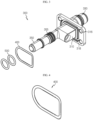
- FIG. 3 is a diagram for illustrating a coolant inflow and outflow pipe of the battery pack of FIG. 2
- FIG. 4 is a diagram for illustrating a first sealing unit of the battery pack of FIG. 2
- FIG. 5 is a diagram for illustrating a second sealing unit of the battery pack of FIG. 2
- FIGS. 6 and 7 are diagrams for illustrating that the coolant inflow and outflow pipe of FIG. 2 is mounted to the first and second sealing units.
- each coolant inflow and outflow pipe 300 may include a pipe body 310, an outer pipe 330, and an inner pipe 350.
- the pipe body 310 may be mounted through the pack case 200. At least a portion of the pipe body 310 may be disposed to contact the outer surface of the pack case 200.
- the pipe body 310 may include a fastening plate 315.
- the fastening plate 315 includes a pack case mounting portion 316 and a first sealing unit insert groove 318.
- the pack case mounting portion 316 is for coupling with the pack case 200, and may be fastened with the pack case 316 by screw coupling or the like. To this end, the pack case mounting portion 316 may be provided as one or more screw holes for screw coupling.
- a first sealing unit 400 may be inserted and mounted in the first sealing unit insert groove 318. Accordingly, the first sealing unit insert groove 318 is provided in a shape corresponding to the first sealing unit 400, explained later.
- the outer pipe 330 protrudes from the pipe body 310 to the outside of the pack case 200, and is connected to the external cooling unit C. Specifically, the outer pipe 330 is provided to protrude out of the pack case 200 from the fastening plate 315 by a predetermined length.
- the inner pipe 350 is disposed to be spaced apart from the outer pipe 330 by a predetermined distance, protrude into the pack case 200 from the pipe body 310, and is connected to the cooling pipe unit 130.
- the inner pipe 350 is connected to the connection pipe 135 through the pipe housing 132 of the cooling pipe unit 130.
- the first sealing unit 400 is for implementing a watertight structure and is provided as an O-ring member. Specifically, the first sealing unit 400 is provided as a planar O-ring member of an approximately rectangular planar shape.
- the first sealing unit 400 provided as such a planar O-ring member is inserted into the first sealing unit insert groove 318 of the fastening plate 315, and then maintains the sealing by a surface pressure generated by compression caused by screw coupling between the fastening plate 315 and the pack case 200.
- the first sealing unit 400 is disposed between the coolant inflow and outflow pipe 300 and the pack case 200. Specifically, the first sealing unit 400 is disposed between the pipe body 310 and the pack case 200. More specifically, the first sealing unit 400 is disposed to contact the outer surface of the pack case 200, and is disposed between the fastening plate 315 and the pack case 200. For this, the first sealing unit 400 is inserted and mounted in the first sealing unit insert groove 318.
- the second sealing unit 500 is for implementing a watertight structure, and may be provided as an O-ring member. Specifically, the second sealing unit 500 may be provided as an axial O-ring member in a circular axial shape.
- the second sealing unit 500 provided as the axial O-ring member may be formed to have a thickness greater than the difference between the outer diameter of the inner pipe 350 and the inner diameter of the pipe housing 132. Accordingly, the second sealing unit 500 may maintain the sealing by the surface pressure generated by compression when the inner pipe 350 and the pipe housing 132 are connected.
- the second sealing unit 500 is disposed to be spaced apart from the first sealing unit 400 by a predetermined distance, and is disposed between the coolant inflow and outflow pipe 300 and the cooling pipe unit 130.
- the second sealing unit 500 is disposed between the inner pipe 350 of the coolant inflow and outflow pipe 300 and the cooling housing 132 of the cooling pipe unit 130.
- At least one second sealing unit 500 or a plurality of second sealing units 500 may be provided.
- a plurality of second sealing units 500 are provided.
- the plurality of second sealing units 500 may be disposed to be spaced apart from each other by a predetermined distance along the longitudinal direction of the inner pipe 350.
- the second sealing unit 500 is provided as a pair so that the pair of second sealing units 500 are spaced apart from each other by a predetermined distance along the longitudinal direction of the inner pipe 350.
- the watertight structure may be more firmly implemented.
- the other sealing structure may compensate for it.
- first sealing unit 400 and the second sealing unit 500 are structurally independent from each other as a planar structure and an axial structure, respectively, they may not affect each other in relation to sealing.
- FIG. 8 is a diagram for illustrating a coolant inflow and outflow pipe according to another embodiment of the present disclosure.
- the coolant inflow and outflow pipe 300 further includes a third sealing unit 600.
- the third sealing unit 600 is to further improve the implementation of the watertight structure, and may be provided as an O-ring member.
- the watertight structure is implemented even inside the pipe housing 132 of the cooling pipe unit 130, and thus the watertight structure may be made more robust.
- FIG. 9 is a diagram for illustrating a vehicle according to an embodiment of the present disclosure.
- the vehicle 1 may include at least one battery pack 10 of the former embodiment.
- the battery pack 10 provided to the vehicle 1 may be provided as a fuel source for the vehicle.
- the battery pack 10 may also be provided to an electric vehicle, a hybrid electric vehicle, and other types of vehicles 1 in which the battery pack 10 may be used as a fuel source.
- a battery pack 10 which may implement a tighter watertight structure in a water-cooled battery pack 10, and a vehicle 1 including the battery pack 10.
Landscapes
- Engineering & Computer Science (AREA)
- Chemical & Material Sciences (AREA)
- Chemical Kinetics & Catalysis (AREA)
- Electrochemistry (AREA)
- General Chemical & Material Sciences (AREA)
- Manufacturing & Machinery (AREA)
- Aviation & Aerospace Engineering (AREA)
- Secondary Cells (AREA)
- Battery Mounting, Suspending (AREA)
Description
- The present disclosure relates to a battery pack and a vehicle including the battery pack.
- The present application claims priority to
Korean Patent Application No. 10-2020-0169918 filed on December 7, 2020 - Secondary batteries which are highly applicable to various products and exhibit superior electrical properties such as high energy density, etc. are commonly used not only in portable devices but also in electric vehicles (EVs) or hybrid electric vehicles (HEVs) driven by electrical power sources. The secondary battery is drawing attentions as a new energy source for enhancing energy efficiency and environment friendliness in that the use of fossil fuels can be reduced greatly and no byproduct is generated during energy consumption.
- Secondary batteries widely used at present include lithium ion batteries, lithium polymer batteries, nickel cadmium batteries, nickel hydrogen batteries, nickel zinc batteries and the like. An operating voltage of the unit secondary battery cell, namely a unit battery cell, is about 2.5V to 4.2V. Therefore, if a higher output voltage is required, a plurality of battery cells may be connected in series to configure a battery pack. In addition, depending on the charge/discharge capacity required for the battery pack, a plurality of battery cells may be connected in parallel to configure a battery pack. Thus, the number of battery cells included in the battery pack may be variously set according to the required output voltage or the demanded charge/discharge capacity.
- Meanwhile, when a plurality of battery cells are connected in series or in parallel to configure a battery pack, it is common to configure a battery module composed of at least one battery cell first, and then configure a battery pack by using at least one battery module and adding other components.
- A conventional battery pack is generally configured to include a pack case mounted to a vehicle, such as an electric vehicle, and at least one battery module provided inside the pack case. Here, at least one battery module may include a water-cooled cooling pipe unit for cooling the battery cells, and the battery pack may further include has a coolant inflow and outflow pipe mounted through the pack case to supply and discharge a coolant using the cooling pipe unit.
- In the conventional battery pack, it is necessary to isolate the cooling water flowing through the water-cooling coolant inflow and outflow pipe and the cooling pipe unit not to come into contact with the battery cells inside the battery pack. That is, it is important to block the risk of the cooling water from flowing to the battery cells inside the battery module.
- Therefore, it is required to find a way to implement a tighter watertight structure in a water-cooled battery pack.
- Further prior art is described in
EP 3 890 099 A1 (filed on 31.03.2020 and published on 06.10.2021),US 10 046 665 B2 US 10 601 088 B2 US 2016/258556 A1 ,DE 10 2014 200174 A1EP 3 522 291 A1 . - The present disclosure is designed to solve the problems of the related art, and therefore the present disclosure is directed to providing a battery pack, which may implement a tighter watertight structure in a water-cooled battery pack, and a vehicle including the battery pack.
- In one aspect of the present disclosure, there is provided a battery pack, comprising: at least one battery module including at least one battery cell and having a cooling pipe unit including a pipe housing and a connection pipe disposed in the pipe housing and including a coolant flow path for cooling the at least one battery cell is formed; a pack case configured to accommodate the at least one battery module; a coolant inflow and outflow pipe mounted through the pack case and connected to the connection pipe inside the pipe housing to supply a coolant to the coolant flow path from the outside of the pack case and discharge the coolant from the coolant flow path to the outside of the pack case; a first sealing unit disposed between the coolant inflow and outflow pipe and the pack case; and a second sealing unit disposed to be spaced apart from the first sealing unit by a predetermined distance and disposed between an inner pipe of the coolant inflow and outflow pipe and the pipe housing of the cooling pipe unit, wherein the coolant inflow and outflow pipe includes a pipe body provided through the pack case and disposed to contact an outer surface of the pack case; an outer pipe configured to protrude out of the pack case from the pipe body and connected to an external cooling unit; and an inner pipe disposed to be spaced apart from the outer pipe by a predetermined distance, configured to protrude into the pack case from the pipe body, and connected to the connection pipe of the cooling pipe unit.
- The first sealing unit may be disposed between the pipe body and the pack case.
- The first sealing unit may be disposed to contact the outer surface of the pack case.
- The pipe body may include a fastening plate disposed at an outer side of the pack case and fastened with the pack case, and the first sealing unit may be disposed between the fastening plate and the pack case.
- The fastening plate may have a first sealing unit insert groove into which the first sealing unit is inserted.
- The second sealing unit may be provided in plural, and the plurality of second sealing units may be arranged to be spaced apart from each other by a predetermined distance along a longitudinal direction of the inner pipe.
- The first sealing unit may be provided as a planar O-ring member.
- The second sealing unit may be provided as an axial O-ring member.
- In addition, the present disclosure also provides a vehicle, comprising at least one battery pack according to the former embodiments.
- According to various embodiments as above, it is possible to provide a battery pack, which may implement a tighter watertight structure in a water-cooled battery pack, and a vehicle including the battery pack.
- The accompanying drawings illustrate a preferred embodiment of the present disclosure and together with the foregoing disclosure, serve to provide further understanding of the technical features of the present disclosure, and thus, the present disclosure is not construed as being limited to the drawing.
-
FIG. 1 is a diagram for illustrating a battery pack according to an embodiment of the present disclosure. -
FIG. 2 is a diagram for illustrating a main part of the battery pack ofFIG. 1 . -
FIG. 3 is a diagram for illustrating a coolant inflow and outflow pipe of the battery pack ofFIG. 2 . -
FIG. 4 is a diagram for illustrating a first sealing unit of the battery pack ofFIG. 2 . -
FIG. 5 is a diagram for illustrating a second sealing unit of the battery pack ofFIG. 2 . -
FIGS. 6 and7 are diagrams for illustrating that the coolant inflow and outflow pipe ofFIG. 2 is mounted to the first and second sealing units. -
FIG. 8 is a diagram for illustrating a coolant inflow and outflow pipe according to another embodiment of the present disclosure. -
FIG. 9 is a diagram for illustrating a vehicle according to an embodiment of the present disclosure. - The present disclosure will become more apparent by describing in detail the embodiments of the present disclosure with reference to the accompanying drawings. It should be understood that the embodiments disclosed herein are illustrative only for better understanding of the present disclosure, and that the present disclosure may be modified in various ways. In addition, for ease understanding of the present disclosure, the accompanying drawings are not drawn to real scale, but the dimensions of some components may be exaggerated.
-
FIG. 1 is a diagram for illustrating a battery pack according to an embodiment of the present disclosure, andFIG. 2 is a diagram for illustrating a main part of the battery pack ofFIG. 1 . - Referring to
FIGS. 1 and2 , thebattery pack 10 may be provided to a vehicle as a fuel source of the vehicle. For example, thebattery pack 10 may be provided to an electric vehicle, a hybrid electric vehicle, a plug-in hybrid vehicle, and various other types of vehicles that may use thebattery pack 10 as a fuel source. - Also, the
battery pack 10 may be provided to other devices, instruments and facilities, such as an energy storage system, using a battery cell as a secondary battery, in addition to the vehicle. - The
battery pack 10 includes abattery module 100, apack case 200, a coolant inflow andoutflow pipe 300, afirst sealing unit 400, and asecond sealing unit 500. - At least one
battery module 100 or a plurality ofbattery modules 100 may be provided. Thebattery module 100 is mounted inside apack case 200, explained later. - The
battery module 100 includes at least abattery cell 110 and acooling pipe unit 130. - The
battery cell 110 is a secondary battery and may be provided as a pouch-type secondary battery, a cylindrical secondary battery, or a prismatic secondary battery. Hereinafter, in this embodiment, thebattery cell 110 will be described as a pouch-type secondary battery. - At least one
battery cell 110 or a plurality ofbattery cells 110 are provided. Hereinafter, in this embodiment, it will be described that thebattery cell 110 is provided in plural so that the plurality ofbattery cells 110 are stacked on each other to be electrically connected with each other. - The
cooling pipe unit 130 is for cooling the at least onebattery cell 110, or the plurality ofbattery cells 110 in this embodiment, and is connected to an external cooling unit C through a coolant inflow andoutflow pipe 300, explained later. - The
cooling pipe unit 130 has a coolant flow path formed for cooling the at least onebattery cell 110 or the plurality ofbattery cells 110. In the coolant flow path, a coolant supplied from the external cooling unit C circulates. - The coolant is a water-cooling type and may be provided as a cooling water. The coolant is supplied through the
coolant inflow pipe 300, explained later, from the external cooling unit C, circulates through the coolant flow path, and is then discharged through thecoolant outflow pipe 300, explained later, to the external cooling unit C again. - The
cooling pipe unit 130 includes apipe housing 132 and aconnection pipe 135. - The
pipe housing 132 forms the appearance of thecooling pipe unit 130. Thepipe housing 132 is disposed between the plurality ofbattery cells 110. - The
connection pipe 135 is disposed in thepipe housing 132 and includes the coolant flow path. Theconnection pipe 135 is connected to the coolant inflow andoutflow pipe 300, explained later, inside thepipe housing 132. - The
pack case 200 accommodates the at least onebattery module 100. In addition to thebattery module 100, thepack case 200 may accommodate various electric components or other components constituting thebattery pack 10. Thepack case 200 may be mounted to other devices, instruments, and facilities, such as the vehicle, the energy storage system, and the like. - The coolant inflow and
outflow pipe 300 is for supplying a coolant from the outside of thepack case 200 to the coolant flow path and discharging the coolant from the coolant flow path to the outside of thepack case 200, and is mounted through thepack case 200 and is connected to thecooling pipe unit 130. - The coolant inflow and
outflow pipe 300 is provided as a pair for supplying and discharging the coolant. - Hereinafter, the pair of coolant inflow and
outflow pipes 300, thefirst sealing unit 400 and thesecond sealing unit 500 will be described in more detail. -
FIG. 3 is a diagram for illustrating a coolant inflow and outflow pipe of the battery pack ofFIG. 2 ,FIG. 4 is a diagram for illustrating a first sealing unit of the battery pack ofFIG. 2 ,FIG. 5 is a diagram for illustrating a second sealing unit of the battery pack ofFIG. 2 , andFIGS. 6 and7 are diagrams for illustrating that the coolant inflow and outflow pipe ofFIG. 2 is mounted to the first and second sealing units. - Referring to
FIGS. 3 to 7 , each coolant inflow andoutflow pipe 300 may include apipe body 310, anouter pipe 330, and aninner pipe 350. - The
pipe body 310 may be mounted through thepack case 200. At least a portion of thepipe body 310 may be disposed to contact the outer surface of thepack case 200. - The
pipe body 310 may include afastening plate 315. - The
fastening plate 315 is disposed at the outer side of thepack case 200, and may be fastened with thepack case 200. - The
fastening plate 315 includes a packcase mounting portion 316 and a first sealingunit insert groove 318. - The pack
case mounting portion 316 is for coupling with thepack case 200, and may be fastened with thepack case 316 by screw coupling or the like. To this end, the packcase mounting portion 316 may be provided as one or more screw holes for screw coupling. - A
first sealing unit 400, explained later, may be inserted and mounted in the first sealingunit insert groove 318. Accordingly, the first sealingunit insert groove 318 is provided in a shape corresponding to thefirst sealing unit 400, explained later. - The
outer pipe 330 protrudes from thepipe body 310 to the outside of thepack case 200, and is connected to the external cooling unit C. Specifically, theouter pipe 330 is provided to protrude out of thepack case 200 from thefastening plate 315 by a predetermined length. - The
inner pipe 350 is disposed to be spaced apart from theouter pipe 330 by a predetermined distance, protrude into thepack case 200 from thepipe body 310, and is connected to thecooling pipe unit 130. - Specifically, at least a portion of the
inner pipe 350 is connected to theconnection pipe 135 through thepipe housing 132 of thecooling pipe unit 130. - The
first sealing unit 400 is for implementing a watertight structure and is provided as an O-ring member. Specifically, thefirst sealing unit 400 is provided as a planar O-ring member of an approximately rectangular planar shape. - The
first sealing unit 400 provided as such a planar O-ring member is inserted into the first sealingunit insert groove 318 of thefastening plate 315, and then maintains the sealing by a surface pressure generated by compression caused by screw coupling between thefastening plate 315 and thepack case 200. - The
first sealing unit 400 is disposed between the coolant inflow andoutflow pipe 300 and thepack case 200. Specifically, thefirst sealing unit 400 is disposed between thepipe body 310 and thepack case 200. More specifically, thefirst sealing unit 400 is disposed to contact the outer surface of thepack case 200, and is disposed between thefastening plate 315 and thepack case 200. For this, thefirst sealing unit 400 is inserted and mounted in the first sealingunit insert groove 318. - The
second sealing unit 500 is for implementing a watertight structure, and may be provided as an O-ring member. Specifically, thesecond sealing unit 500 may be provided as an axial O-ring member in a circular axial shape. - The
second sealing unit 500 provided as the axial O-ring member may be formed to have a thickness greater than the difference between the outer diameter of theinner pipe 350 and the inner diameter of thepipe housing 132. Accordingly, thesecond sealing unit 500 may maintain the sealing by the surface pressure generated by compression when theinner pipe 350 and thepipe housing 132 are connected. - The
second sealing unit 500 is disposed to be spaced apart from thefirst sealing unit 400 by a predetermined distance, and is disposed between the coolant inflow andoutflow pipe 300 and thecooling pipe unit 130. - Specifically, the
second sealing unit 500 is disposed between theinner pipe 350 of the coolant inflow andoutflow pipe 300 and the coolinghousing 132 of thecooling pipe unit 130. - At least one
second sealing unit 500 or a plurality ofsecond sealing units 500 may be provided. Hereinafter, in this embodiment, it will be described that a plurality ofsecond sealing units 500 are provided. - The plurality of
second sealing units 500 may be disposed to be spaced apart from each other by a predetermined distance along the longitudinal direction of theinner pipe 350. Specifically, in this embodiment, thesecond sealing unit 500 is provided as a pair so that the pair ofsecond sealing units 500 are spaced apart from each other by a predetermined distance along the longitudinal direction of theinner pipe 350. In this embodiment, since thesecond sealing unit 500 is provided as a pair and the pair ofsecond sealing units 500 are spaced apart from each other, the watertight structure may be more firmly implemented. - As such, in this embodiment, by means of the
second sealing unit 500 and thefirst sealing unit 400, it is possible to implement a more robust watertight structure in both the coolinghousing 132 of thecooling pipe unit 130 and thepack case 200. - Moreover, in this embodiment, by means of the two sealing structures of the
first sealing unit 400 and thesecond sealing unit 500, even if any one sealing structure has a problem, the other sealing structure may compensate for it. - In addition, in this embodiment, since the
first sealing unit 400 and thesecond sealing unit 500 are structurally independent from each other as a planar structure and an axial structure, respectively, they may not affect each other in relation to sealing. -
FIG. 8 is a diagram for illustrating a coolant inflow and outflow pipe according to another embodiment of the present disclosure. - Referring to
FIG. 8 , the coolant inflow andoutflow pipe 300 further includes athird sealing unit 600. - The
third sealing unit 600 is to further improve the implementation of the watertight structure, and may be provided as an O-ring member. In this embodiment, by means of thethird sealing unit 600, the watertight structure is implemented even inside thepipe housing 132 of thecooling pipe unit 130, and thus the watertight structure may be made more robust. -
FIG. 9 is a diagram for illustrating a vehicle according to an embodiment of the present disclosure. - Referring to
FIG. 9 , the vehicle 1 according to this embodiment may include at least onebattery pack 10 of the former embodiment. Thebattery pack 10 provided to the vehicle 1 may be provided as a fuel source for the vehicle. As an example, thebattery pack 10 may also be provided to an electric vehicle, a hybrid electric vehicle, and other types of vehicles 1 in which thebattery pack 10 may be used as a fuel source. - According to various embodiments as described above, it is possible to provide a
battery pack 10, which may implement a tighter watertight structure in a water-cooledbattery pack 10, and a vehicle 1 including thebattery pack 10. - While the embodiments of the present disclosure have been shown and described, it should be understood that the present disclosure is not limited to the specific embodiments described, and that various changes and modifications can be made within the scope of the present claims by those skilled in the art, and these modifications should not be understood individually from the technical ideas and views of the present disclosure.
Claims (9)
- A battery pack (10), comprising:at least one battery module (100) including at least one battery cell (110) and having a cooling pipe unit (130) including a pipe housing (132) and a connection pipe (135) disposed in the pipe housing (132) and including a coolant flow path for cooling the at least one battery cell (110);a pack case (200) configured to accommodate the at least one battery module (100);a coolant inflow and outflow pipe (300) mounted through the pack case (200) and connected to the connection pipe (135) inside the pipe housing (132) to supply a coolant to the coolant flow path from the outside of the pack case (200) and discharge the coolant from the coolant flow path to the outside of the pack case (200);a first sealing unit (400) disposed between the coolant inflow and outflow pipe (300) and the pack case (200); anda second sealing unit (500) disposed to be spaced apart from the first sealing unit (400) by a predetermined distance and disposed between an inner pipe (350) of the coolant inflow and outflow pipe (300) and the pipe housing (132) of the cooling pipe unit (130),wherein the coolant inflow and outflow pipe (300) includes:a pipe body (310) provided through the pack case (200) and disposed to contact an outer surface of the pack case (200);an outer pipe (330) configured to protrude out of the pack case (200) from the pipe body (310) and connected to an external cooling unit (C); andthe inner pipe (350) disposed to be spaced apart from the outer pipe (330) by a predetermined distance, configured to protrude into the pack case (200) from the pipe body (310), and connected to the connection pipe (135) of the cooling pipe unit (130).
- The battery pack (10) according to claim 1,
wherein the first sealing unit (400) is disposed between the pipe body (310) and the pack case (200). - The battery pack (10) according to claim 1,
wherein the first sealing unit (400) is disposed to contact the outer surface of the pack case (200). - The battery pack (10) according to claim 1,wherein the pipe body (310) includes a fastening plate (315) disposed at an outer side of the pack case (200) and fastened with the pack case (200), andthe first sealing unit (400) is disposed between the fastening plate (315) and the pack case (200).
- The battery pack (10) according to claim 4,
wherein the fastening plate (315) has a first sealing unit insert groove (318) into which the first sealing unit (400) is inserted. - The battery pack (10) according to claim 1,
wherein the second sealing unit (500) is provided in plural, and the plurality of second sealing units (500) are arranged to be spaced apart from each other by a predetermined distance along a longitudinal direction of the inner pipe (350). - The battery pack (10) according to claim 1,
wherein the first sealing unit (400) is provided as a planar O-ring member. - The battery pack (10) according to claim 1,
wherein the second sealing unit (500) is provided as an axial O-ring member. - A vehicle, comprising at least one battery pack (10) according to claim 1.
Applications Claiming Priority (2)
| Application Number | Priority Date | Filing Date | Title |
|---|---|---|---|
| KR1020200169918A KR102954892B1 (en) | 2020-12-07 | Battery pack and vehicle comprising the battery pack | |
| PCT/KR2021/018164 WO2022124700A1 (en) | 2020-12-07 | 2021-12-02 | Battery pack and vehicle comprising battery pack |
Publications (3)
| Publication Number | Publication Date |
|---|---|
| EP4145595A1 EP4145595A1 (en) | 2023-03-08 |
| EP4145595A4 EP4145595A4 (en) | 2023-12-06 |
| EP4145595B1 true EP4145595B1 (en) | 2025-04-30 |
Family
ID=81974723
Family Applications (1)
| Application Number | Title | Priority Date | Filing Date |
|---|---|---|---|
| EP21903746.2A Active EP4145595B1 (en) | 2020-12-07 | 2021-12-02 | Battery pack and vehicle comprising battery pack |
Country Status (7)
| Country | Link |
|---|---|
| US (1) | US12519158B2 (en) |
| EP (1) | EP4145595B1 (en) |
| JP (1) | JP7538888B2 (en) |
| CN (1) | CN115668593A (en) |
| ES (1) | ES3029374T3 (en) |
| HU (1) | HUE071478T2 (en) |
| WO (1) | WO2022124700A1 (en) |
Families Citing this family (3)
| Publication number | Priority date | Publication date | Assignee | Title |
|---|---|---|---|---|
| KR20220092269A (en) * | 2020-12-24 | 2022-07-01 | 현대모비스 주식회사 | Hose connection joint structure for battery cooling system |
| KR20230010501A (en) * | 2021-07-12 | 2023-01-19 | 주식회사 엘지에너지솔루션 | Battery pack and device including the same |
| DE102023211973A1 (en) * | 2023-11-29 | 2025-06-05 | Volkswagen Aktiengesellschaft | Cooling arrangement |
Family Cites Families (25)
| Publication number | Priority date | Publication date | Assignee | Title |
|---|---|---|---|---|
| US6386593B1 (en) * | 1999-10-29 | 2002-05-14 | Automotive Fluid Systems, Inc. | Dual-plane seal for fluid-tight conduit connection |
| EP2436956B1 (en) * | 2009-05-27 | 2015-10-28 | Mitsubishi Heavy Industries, Ltd. | Seal structure for circular tube body |
| KR101987778B1 (en) * | 2012-05-11 | 2019-06-11 | 에스케이이노베이션 주식회사 | Secondary battery module having through type cool channel |
| JP5989515B2 (en) * | 2012-11-19 | 2016-09-07 | トヨタ自動車株式会社 | Inverter with integrated cooler |
| JP2015020685A (en) * | 2013-07-23 | 2015-02-02 | 株式会社ヴァレオジャパン | Seal member and storage battery temperature regulation apparatus using seal member |
| DE102014200174A1 (en) * | 2014-01-09 | 2015-07-23 | Robert Bosch Gmbh | Battery pack with external cooling system interfaces |
| US9879781B2 (en) * | 2015-03-06 | 2018-01-30 | Ford Global Technologies, Llc | Plated sealing system for vehicle assembly |
| EP3286476B1 (en) * | 2015-04-23 | 2019-10-02 | Swagelok Company | Push to connect fitting assembly for a conduit |
| JP6296027B2 (en) * | 2015-09-04 | 2018-03-20 | トヨタ自動車株式会社 | Refrigerant passage connection structure |
| KR102050531B1 (en) | 2015-11-02 | 2019-11-29 | 주식회사 엘지화학 | Battery pack and vehicle comprising the battery pack |
| KR102089646B1 (en) | 2016-01-29 | 2020-03-16 | 주식회사 엘지화학 | Battery pack and vehicle comprising the battery pack |
| US20180123201A1 (en) * | 2016-10-28 | 2018-05-03 | Inevit, Llc | Battery module cooling tube including an integrated turbulator component and method thereof |
| JP2017027962A (en) * | 2016-11-08 | 2017-02-02 | 三洋電機株式会社 | Battery system for vehicle and electrically powered vehicle equipped with battery system |
| KR101750029B1 (en) | 2017-02-24 | 2017-06-23 | 엠에이치기술개발 주식회사 | Cooling apparatus for battery and manufacturing method of the same |
| DE102017215610A1 (en) * | 2017-09-05 | 2019-03-07 | Mahle International Gmbh | Accumulator assembly for an electric or hybrid vehicle |
| KR20190032843A (en) | 2017-09-20 | 2019-03-28 | 에스케이이노베이션 주식회사 | Battery Module for Secondary Battery and Battery Pack having the Same |
| KR102002862B1 (en) | 2017-12-13 | 2019-07-23 | 주식회사 세광정밀 | Manufacturing method of integrated die-casting type water-cooled battery pack cooling apparatus |
| PL3522291T3 (en) * | 2018-01-31 | 2022-01-31 | Samsung Sdi Co., Ltd. | Tube assembly for a fluid distribution system of a battery pack of a vehicle and battery pack for a vehicle |
| KR102596227B1 (en) * | 2018-07-25 | 2023-11-01 | 현대자동차주식회사 | Cooling apparatus of battery for electric vehicles |
| KR102660832B1 (en) | 2018-08-09 | 2024-04-24 | 주식회사 엘지에너지솔루션 | Battery pack and vehicle comprising the battery pack |
| KR102669179B1 (en) | 2018-10-11 | 2024-05-27 | 에스케이온 주식회사 | Cooling pipe connector and battery pack having the same |
| KR102704780B1 (en) | 2018-11-23 | 2024-09-06 | 주식회사 엘지에너지솔루션 | Secondary battery, and device including the same |
| KR102792205B1 (en) | 2019-03-06 | 2025-04-04 | 주식회사 엘지에너지솔루션 | Battery pack and device including the same |
| KR102763672B1 (en) | 2019-04-08 | 2025-02-07 | 에스케이온 주식회사 | Battery pack |
| EP3890099B1 (en) * | 2020-03-31 | 2022-03-23 | Samsung SDI Co., Ltd. | Robust interface for cooler to housing |
-
2021
- 2021-12-02 JP JP2022570390A patent/JP7538888B2/en active Active
- 2021-12-02 CN CN202180038638.2A patent/CN115668593A/en active Pending
- 2021-12-02 WO PCT/KR2021/018164 patent/WO2022124700A1/en not_active Ceased
- 2021-12-02 HU HUE21903746A patent/HUE071478T2/en unknown
- 2021-12-02 EP EP21903746.2A patent/EP4145595B1/en active Active
- 2021-12-02 ES ES21903746T patent/ES3029374T3/en active Active
- 2021-12-02 US US17/922,743 patent/US12519158B2/en active Active
Also Published As
| Publication number | Publication date |
|---|---|
| JP7538888B2 (en) | 2024-08-22 |
| US12519158B2 (en) | 2026-01-06 |
| CN115668593A (en) | 2023-01-31 |
| EP4145595A1 (en) | 2023-03-08 |
| ES3029374T3 (en) | 2025-06-24 |
| US20230170553A1 (en) | 2023-06-01 |
| JP2023526828A (en) | 2023-06-23 |
| KR20260045775A (en) | 2026-04-03 |
| HUE071478T2 (en) | 2025-08-28 |
| KR20220080621A (en) | 2022-06-14 |
| WO2022124700A1 (en) | 2022-06-16 |
| EP4145595A4 (en) | 2023-12-06 |
Similar Documents
| Publication | Publication Date | Title |
|---|---|---|
| US11876199B2 (en) | Battery module, battery pack comprising same battery module, and vehicle comprising same battery pack | |
| US10497994B2 (en) | Battery pack and vehicle including such battery pack | |
| EP3958375B1 (en) | Battery rack and power storage device comprising same | |
| EP3836244B1 (en) | Battery module and battery pack comprising battery module | |
| EP4145595B1 (en) | Battery pack and vehicle comprising battery pack | |
| US12002938B2 (en) | Battery rack and power storage device comprising same | |
| EP3800694A1 (en) | Battery cell assembly, battery module including same battery cell assembly, battery pack including same battery module, and automobile including same battery pack | |
| US11522239B2 (en) | Battery module, battery pack including battery module, and vehicle including battery pack | |
| US11018391B2 (en) | Battery cell, battery module, and battery pack and vehicle including the same | |
| EP3742542A1 (en) | Battery module, battery pack comprising battery module, and vehicle comprising battery pack | |
| US12500287B2 (en) | Battery pack and vehicle comprising battery pack | |
| KR20170103228A (en) | Battery module, battery pack comprising the battery module and vehicle comprising the battery pack | |
| EP3848995A1 (en) | Battery pack and vehicle comprising same battery pack | |
| KR102954780B1 (en) | Battery pack and vehicle comprising the battery pack | |
| KR102954892B1 (en) | Battery pack and vehicle comprising the battery pack | |
| KR20260051351A (en) | Battery pack and vehicle comprising the battery pack | |
| EP4661160A1 (en) | Battery pack and vehicle comprising same | |
| EP4576353A1 (en) | Battery cell and, battery module including same, and battery pack including same, and vehicle including same | |
| CN121460773A (en) | Battery pack, electric equipment and energy storage device | |
| KR20170043306A (en) | Battery module, battery pack comprising the battery module and vehicle comprising the battery pack |
Legal Events
| Date | Code | Title | Description |
|---|---|---|---|
| STAA | Information on the status of an ep patent application or granted ep patent |
Free format text: STATUS: THE INTERNATIONAL PUBLICATION HAS BEEN MADE |
|
| PUAI | Public reference made under article 153(3) epc to a published international application that has entered the european phase |
Free format text: ORIGINAL CODE: 0009012 |
|
| STAA | Information on the status of an ep patent application or granted ep patent |
Free format text: STATUS: REQUEST FOR EXAMINATION WAS MADE |
|
| 17P | Request for examination filed |
Effective date: 20221130 |
|
| AK | Designated contracting states |
Kind code of ref document: A1 Designated state(s): AL AT BE BG CH CY CZ DE DK EE ES FI FR GB GR HR HU IE IS IT LI LT LU LV MC MK MT NL NO PL PT RO RS SE SI SK SM TR |
|
| A4 | Supplementary search report drawn up and despatched |
Effective date: 20231106 |
|
| RIC1 | Information provided on ipc code assigned before grant |
Ipc: H01M 50/249 20210101ALI20231030BHEP Ipc: H01M 10/613 20140101ALI20231030BHEP Ipc: H01M 10/625 20140101ALI20231030BHEP Ipc: H01M 10/6567 20140101ALI20231030BHEP Ipc: H01M 10/6556 20140101AFI20231030BHEP |
|
| DAV | Request for validation of the european patent (deleted) | ||
| DAX | Request for extension of the european patent (deleted) | ||
| STAA | Information on the status of an ep patent application or granted ep patent |
Free format text: STATUS: EXAMINATION IS IN PROGRESS |
|
| 17Q | First examination report despatched |
Effective date: 20240709 |
|
| GRAP | Despatch of communication of intention to grant a patent |
Free format text: ORIGINAL CODE: EPIDOSNIGR1 |
|
| STAA | Information on the status of an ep patent application or granted ep patent |
Free format text: STATUS: GRANT OF PATENT IS INTENDED |
|
| INTG | Intention to grant announced |
Effective date: 20250123 |
|
| P01 | Opt-out of the competence of the unified patent court (upc) registered |
Free format text: CASE NUMBER: APP_6064/2025 Effective date: 20250205 |
|
| GRAS | Grant fee paid |
Free format text: ORIGINAL CODE: EPIDOSNIGR3 |
|
| GRAA | (expected) grant |
Free format text: ORIGINAL CODE: 0009210 |
|
| STAA | Information on the status of an ep patent application or granted ep patent |
Free format text: STATUS: THE PATENT HAS BEEN GRANTED |
|
| AK | Designated contracting states |
Kind code of ref document: B1 Designated state(s): AL AT BE BG CH CY CZ DE DK EE ES FI FR GB GR HR HU IE IS IT LI LT LU LV MC MK MT NL NO PL PT RO RS SE SI SK SM TR |
|
| REG | Reference to a national code |
Ref country code: CH Ref legal event code: EP Ref country code: GB Ref legal event code: FG4D |
|
| REG | Reference to a national code |
Ref country code: DE Ref legal event code: R096 Ref document number: 602021030179 Country of ref document: DE |
|
| REG | Reference to a national code |
Ref country code: IE Ref legal event code: FG4D |
|
| REG | Reference to a national code |
Ref country code: ES Ref legal event code: FG2A Ref document number: 3029374 Country of ref document: ES Kind code of ref document: T3 Effective date: 20250624 |
|
| REG | Reference to a national code |
Ref country code: HU Ref legal event code: AG4A Ref document number: E071478 Country of ref document: HU |
|
| REG | Reference to a national code |
Ref country code: NL Ref legal event code: MP Effective date: 20250430 |
|
| REG | Reference to a national code |
Ref country code: AT Ref legal event code: MK05 Ref document number: 1790956 Country of ref document: AT Kind code of ref document: T Effective date: 20250430 |
|
| PG25 | Lapsed in a contracting state [announced via postgrant information from national office to epo] |
Ref country code: FI Free format text: LAPSE BECAUSE OF FAILURE TO SUBMIT A TRANSLATION OF THE DESCRIPTION OR TO PAY THE FEE WITHIN THE PRESCRIBED TIME-LIMIT Effective date: 20250430 Ref country code: PT Free format text: LAPSE BECAUSE OF FAILURE TO SUBMIT A TRANSLATION OF THE DESCRIPTION OR TO PAY THE FEE WITHIN THE PRESCRIBED TIME-LIMIT Effective date: 20250901 |
|
| REG | Reference to a national code |
Ref country code: LT Ref legal event code: MG9D |
|
| PG25 | Lapsed in a contracting state [announced via postgrant information from national office to epo] |
Ref country code: NO Free format text: LAPSE BECAUSE OF FAILURE TO SUBMIT A TRANSLATION OF THE DESCRIPTION OR TO PAY THE FEE WITHIN THE PRESCRIBED TIME-LIMIT Effective date: 20250730 Ref country code: GR Free format text: LAPSE BECAUSE OF FAILURE TO SUBMIT A TRANSLATION OF THE DESCRIPTION OR TO PAY THE FEE WITHIN THE PRESCRIBED TIME-LIMIT Effective date: 20250731 |
|
| PG25 | Lapsed in a contracting state [announced via postgrant information from national office to epo] |
Ref country code: NL Free format text: LAPSE BECAUSE OF FAILURE TO SUBMIT A TRANSLATION OF THE DESCRIPTION OR TO PAY THE FEE WITHIN THE PRESCRIBED TIME-LIMIT Effective date: 20250430 Ref country code: PL Free format text: LAPSE BECAUSE OF FAILURE TO SUBMIT A TRANSLATION OF THE DESCRIPTION OR TO PAY THE FEE WITHIN THE PRESCRIBED TIME-LIMIT Effective date: 20250430 |
|
| PG25 | Lapsed in a contracting state [announced via postgrant information from national office to epo] |
Ref country code: BG Free format text: LAPSE BECAUSE OF FAILURE TO SUBMIT A TRANSLATION OF THE DESCRIPTION OR TO PAY THE FEE WITHIN THE PRESCRIBED TIME-LIMIT Effective date: 20250430 |
|
| PG25 | Lapsed in a contracting state [announced via postgrant information from national office to epo] |
Ref country code: HR Free format text: LAPSE BECAUSE OF FAILURE TO SUBMIT A TRANSLATION OF THE DESCRIPTION OR TO PAY THE FEE WITHIN THE PRESCRIBED TIME-LIMIT Effective date: 20250430 |
|
| PG25 | Lapsed in a contracting state [announced via postgrant information from national office to epo] |
Ref country code: AT Free format text: LAPSE BECAUSE OF FAILURE TO SUBMIT A TRANSLATION OF THE DESCRIPTION OR TO PAY THE FEE WITHIN THE PRESCRIBED TIME-LIMIT Effective date: 20250430 |
|
| PG25 | Lapsed in a contracting state [announced via postgrant information from national office to epo] |
Ref country code: RS Free format text: LAPSE BECAUSE OF FAILURE TO SUBMIT A TRANSLATION OF THE DESCRIPTION OR TO PAY THE FEE WITHIN THE PRESCRIBED TIME-LIMIT Effective date: 20250731 |
|
| PG25 | Lapsed in a contracting state [announced via postgrant information from national office to epo] |
Ref country code: IS Free format text: LAPSE BECAUSE OF FAILURE TO SUBMIT A TRANSLATION OF THE DESCRIPTION OR TO PAY THE FEE WITHIN THE PRESCRIBED TIME-LIMIT Effective date: 20250830 |
|
| PG25 | Lapsed in a contracting state [announced via postgrant information from national office to epo] |
Ref country code: LV Free format text: LAPSE BECAUSE OF FAILURE TO SUBMIT A TRANSLATION OF THE DESCRIPTION OR TO PAY THE FEE WITHIN THE PRESCRIBED TIME-LIMIT Effective date: 20250430 |
|
| PGFP | Annual fee paid to national office [announced via postgrant information from national office to epo] |
Ref country code: DE Payment date: 20251120 Year of fee payment: 5 |
|
| PGFP | Annual fee paid to national office [announced via postgrant information from national office to epo] |
Ref country code: GB Payment date: 20251120 Year of fee payment: 5 |
|
| PG25 | Lapsed in a contracting state [announced via postgrant information from national office to epo] |
Ref country code: SM Free format text: LAPSE BECAUSE OF FAILURE TO SUBMIT A TRANSLATION OF THE DESCRIPTION OR TO PAY THE FEE WITHIN THE PRESCRIBED TIME-LIMIT Effective date: 20250430 Ref country code: DK Free format text: LAPSE BECAUSE OF FAILURE TO SUBMIT A TRANSLATION OF THE DESCRIPTION OR TO PAY THE FEE WITHIN THE PRESCRIBED TIME-LIMIT Effective date: 20250430 |
|
| PGFP | Annual fee paid to national office [announced via postgrant information from national office to epo] |
Ref country code: HU Payment date: 20251216 Year of fee payment: 5 Ref country code: FR Payment date: 20251125 Year of fee payment: 5 |
|
| PGFP | Annual fee paid to national office [announced via postgrant information from national office to epo] |
Ref country code: BE Payment date: 20251120 Year of fee payment: 5 |
|
| PG25 | Lapsed in a contracting state [announced via postgrant information from national office to epo] |
Ref country code: CZ Free format text: LAPSE BECAUSE OF FAILURE TO SUBMIT A TRANSLATION OF THE DESCRIPTION OR TO PAY THE FEE WITHIN THE PRESCRIBED TIME-LIMIT Effective date: 20250430 |
|
| PG25 | Lapsed in a contracting state [announced via postgrant information from national office to epo] |
Ref country code: EE Free format text: LAPSE BECAUSE OF FAILURE TO SUBMIT A TRANSLATION OF THE DESCRIPTION OR TO PAY THE FEE WITHIN THE PRESCRIBED TIME-LIMIT Effective date: 20250430 |
|
| PG25 | Lapsed in a contracting state [announced via postgrant information from national office to epo] |
Ref country code: SK Free format text: LAPSE BECAUSE OF FAILURE TO SUBMIT A TRANSLATION OF THE DESCRIPTION OR TO PAY THE FEE WITHIN THE PRESCRIBED TIME-LIMIT Effective date: 20250430 |
|
| PG25 | Lapsed in a contracting state [announced via postgrant information from national office to epo] |
Ref country code: IT Free format text: LAPSE BECAUSE OF FAILURE TO SUBMIT A TRANSLATION OF THE DESCRIPTION OR TO PAY THE FEE WITHIN THE PRESCRIBED TIME-LIMIT Effective date: 20250430 |
|
| REG | Reference to a national code |
Ref country code: DE Ref legal event code: R097 Ref document number: 602021030179 Country of ref document: DE |
|
| PG25 | Lapsed in a contracting state [announced via postgrant information from national office to epo] |
Ref country code: RO Free format text: LAPSE BECAUSE OF FAILURE TO SUBMIT A TRANSLATION OF THE DESCRIPTION OR TO PAY THE FEE WITHIN THE PRESCRIBED TIME-LIMIT Effective date: 20250430 |
|
| PLBE | No opposition filed within time limit |
Free format text: ORIGINAL CODE: 0009261 |
|
| STAA | Information on the status of an ep patent application or granted ep patent |
Free format text: STATUS: NO OPPOSITION FILED WITHIN TIME LIMIT |
|
| REG | Reference to a national code |
Ref country code: CH Ref legal event code: L10 Free format text: ST27 STATUS EVENT CODE: U-0-0-L10-L00 (AS PROVIDED BY THE NATIONAL OFFICE) Effective date: 20260311 |
|
| 26N | No opposition filed |
Effective date: 20260202 |
|
| PGFP | Annual fee paid to national office [announced via postgrant information from national office to epo] |
Ref country code: ES Payment date: 20260122 Year of fee payment: 5 |