EP4145485A1 - Direct current contactor and vehicle - Google Patents
Direct current contactor and vehicle Download PDFInfo
- Publication number
- EP4145485A1 EP4145485A1 EP21829112.8A EP21829112A EP4145485A1 EP 4145485 A1 EP4145485 A1 EP 4145485A1 EP 21829112 A EP21829112 A EP 21829112A EP 4145485 A1 EP4145485 A1 EP 4145485A1
- Authority
- EP
- European Patent Office
- Prior art keywords
- magnet
- moving
- arc
- direct current
- contact
- Prior art date
- Legal status (The legal status is an assumption and is not a legal conclusion. Google has not performed a legal analysis and makes no representation as to the accuracy of the status listed.)
- Pending
Links
Images


Classifications
-
- H—ELECTRICITY
- H01—ELECTRIC ELEMENTS
- H01H—ELECTRIC SWITCHES; RELAYS; SELECTORS; EMERGENCY PROTECTIVE DEVICES
- H01H73/00—Protective overload circuit-breaking switches in which excess current opens the contacts by automatic release of mechanical energy stored by previous operation of a hand reset mechanism
- H01H73/02—Details
- H01H73/18—Means for extinguishing or suppressing arc
-
- H—ELECTRICITY
- H01—ELECTRIC ELEMENTS
- H01H—ELECTRIC SWITCHES; RELAYS; SELECTORS; EMERGENCY PROTECTIVE DEVICES
- H01H50/00—Details of electromagnetic relays
- H01H50/02—Bases; Casings; Covers
- H01H50/04—Mounting complete relay or separate parts of relay on a base or inside a case
- H01H50/041—Details concerning assembly of relays
- H01H50/045—Details particular to contactors
-
- H—ELECTRICITY
- H01—ELECTRIC ELEMENTS
- H01H—ELECTRIC SWITCHES; RELAYS; SELECTORS; EMERGENCY PROTECTIVE DEVICES
- H01H50/00—Details of electromagnetic relays
- H01H50/54—Contact arrangements
-
- B—PERFORMING OPERATIONS; TRANSPORTING
- B60—VEHICLES IN GENERAL
- B60L—PROPULSION OF ELECTRICALLY-PROPELLED VEHICLES; SUPPLYING ELECTRIC POWER FOR AUXILIARY EQUIPMENT OF ELECTRICALLY-PROPELLED VEHICLES; ELECTRODYNAMIC BRAKE SYSTEMS FOR VEHICLES IN GENERAL; MAGNETIC SUSPENSION OR LEVITATION FOR VEHICLES; MONITORING OPERATING VARIABLES OF ELECTRICALLY-PROPELLED VEHICLES; ELECTRIC SAFETY DEVICES FOR ELECTRICALLY-PROPELLED VEHICLES
- B60L53/00—Methods of charging batteries, specially adapted for electric vehicles; Charging stations or on-board charging equipment therefor; Exchange of energy storage elements in electric vehicles
-
- B—PERFORMING OPERATIONS; TRANSPORTING
- B60—VEHICLES IN GENERAL
- B60R—VEHICLES, VEHICLE FITTINGS, OR VEHICLE PARTS, NOT OTHERWISE PROVIDED FOR
- B60R16/00—Electric or fluid circuits specially adapted for vehicles and not otherwise provided for; Arrangement of elements of electric or fluid circuits specially adapted for vehicles and not otherwise provided for
- B60R16/02—Electric or fluid circuits specially adapted for vehicles and not otherwise provided for; Arrangement of elements of electric or fluid circuits specially adapted for vehicles and not otherwise provided for electric constitutive elements
-
- H—ELECTRICITY
- H01—ELECTRIC ELEMENTS
- H01H—ELECTRIC SWITCHES; RELAYS; SELECTORS; EMERGENCY PROTECTIVE DEVICES
- H01H50/00—Details of electromagnetic relays
- H01H50/02—Bases; Casings; Covers
-
- H—ELECTRICITY
- H01—ELECTRIC ELEMENTS
- H01H—ELECTRIC SWITCHES; RELAYS; SELECTORS; EMERGENCY PROTECTIVE DEVICES
- H01H50/00—Details of electromagnetic relays
- H01H50/54—Contact arrangements
- H01H50/546—Contact arrangements for contactors having bridging contacts
-
- H—ELECTRICITY
- H01—ELECTRIC ELEMENTS
- H01H—ELECTRIC SWITCHES; RELAYS; SELECTORS; EMERGENCY PROTECTIVE DEVICES
- H01H50/00—Details of electromagnetic relays
- H01H50/54—Contact arrangements
- H01H50/56—Contact spring sets
- H01H50/58—Driving arrangements structurally associated therewith; Mounting of driving arrangements on armature
-
- H—ELECTRICITY
- H01—ELECTRIC ELEMENTS
- H01H—ELECTRIC SWITCHES; RELAYS; SELECTORS; EMERGENCY PROTECTIVE DEVICES
- H01H50/00—Details of electromagnetic relays
- H01H50/54—Contact arrangements
- H01H50/60—Contact arrangements moving contact being rigidly combined with movable part of magnetic circuit
-
- H—ELECTRICITY
- H01—ELECTRIC ELEMENTS
- H01H—ELECTRIC SWITCHES; RELAYS; SELECTORS; EMERGENCY PROTECTIVE DEVICES
- H01H9/00—Details of switching devices, not covered by groups H01H1/00 - H01H7/00
- H01H9/30—Means for extinguishing or preventing arc between current-carrying parts
- H01H9/34—Stationary parts for restricting or subdividing the arc, e.g. barrier plate
-
- H—ELECTRICITY
- H01—ELECTRIC ELEMENTS
- H01H—ELECTRIC SWITCHES; RELAYS; SELECTORS; EMERGENCY PROTECTIVE DEVICES
- H01H9/00—Details of switching devices, not covered by groups H01H1/00 - H01H7/00
- H01H9/30—Means for extinguishing or preventing arc between current-carrying parts
- H01H9/44—Means for extinguishing or preventing arc between current-carrying parts using blow-out magnet
- H01H9/443—Means for extinguishing or preventing arc between current-carrying parts using blow-out magnet using permanent magnets
-
- H—ELECTRICITY
- H01—ELECTRIC ELEMENTS
- H01H—ELECTRIC SWITCHES; RELAYS; SELECTORS; EMERGENCY PROTECTIVE DEVICES
- H01H50/00—Details of electromagnetic relays
- H01H50/02—Bases; Casings; Covers
- H01H2050/028—Means to improve the overall withstanding voltage, e.g. creepage distances
-
- H—ELECTRICITY
- H01—ELECTRIC ELEMENTS
- H01H—ELECTRIC SWITCHES; RELAYS; SELECTORS; EMERGENCY PROTECTIVE DEVICES
- H01H50/00—Details of electromagnetic relays
- H01H50/16—Magnetic circuit arrangements
- H01H50/36—Stationary parts of magnetic circuit, e.g. yoke
- H01H50/38—Part of main magnetic circuit shaped to suppress arcing between the contacts of the relay
-
- Y—GENERAL TAGGING OF NEW TECHNOLOGICAL DEVELOPMENTS; GENERAL TAGGING OF CROSS-SECTIONAL TECHNOLOGIES SPANNING OVER SEVERAL SECTIONS OF THE IPC; TECHNICAL SUBJECTS COVERED BY FORMER USPC CROSS-REFERENCE ART COLLECTIONS [XRACs] AND DIGESTS
- Y02—TECHNOLOGIES OR APPLICATIONS FOR MITIGATION OR ADAPTATION AGAINST CLIMATE CHANGE
- Y02T—CLIMATE CHANGE MITIGATION TECHNOLOGIES RELATED TO TRANSPORTATION
- Y02T10/00—Road transport of goods or passengers
- Y02T10/60—Other road transportation technologies with climate change mitigation effect
- Y02T10/70—Energy storage systems for electromobility, e.g. batteries
-
- Y—GENERAL TAGGING OF NEW TECHNOLOGICAL DEVELOPMENTS; GENERAL TAGGING OF CROSS-SECTIONAL TECHNOLOGIES SPANNING OVER SEVERAL SECTIONS OF THE IPC; TECHNICAL SUBJECTS COVERED BY FORMER USPC CROSS-REFERENCE ART COLLECTIONS [XRACs] AND DIGESTS
- Y02—TECHNOLOGIES OR APPLICATIONS FOR MITIGATION OR ADAPTATION AGAINST CLIMATE CHANGE
- Y02T—CLIMATE CHANGE MITIGATION TECHNOLOGIES RELATED TO TRANSPORTATION
- Y02T10/00—Road transport of goods or passengers
- Y02T10/60—Other road transportation technologies with climate change mitigation effect
- Y02T10/7072—Electromobility specific charging systems or methods for batteries, ultracapacitors, supercapacitors or double-layer capacitors
-
- Y—GENERAL TAGGING OF NEW TECHNOLOGICAL DEVELOPMENTS; GENERAL TAGGING OF CROSS-SECTIONAL TECHNOLOGIES SPANNING OVER SEVERAL SECTIONS OF THE IPC; TECHNICAL SUBJECTS COVERED BY FORMER USPC CROSS-REFERENCE ART COLLECTIONS [XRACs] AND DIGESTS
- Y02—TECHNOLOGIES OR APPLICATIONS FOR MITIGATION OR ADAPTATION AGAINST CLIMATE CHANGE
- Y02T—CLIMATE CHANGE MITIGATION TECHNOLOGIES RELATED TO TRANSPORTATION
- Y02T90/00—Enabling technologies or technologies with a potential or indirect contribution to GHG emissions mitigation
- Y02T90/10—Technologies relating to charging of electric vehicles
- Y02T90/14—Plug-in electric vehicles
Abstract
Description
- This application claims priority to
Chinese Patent Application No. 202010591488.5, filed with the China National Intellectual Property Administration on June 24, 2020 - This application relates to the field of electric power technologies, and in particular, to a direct current contactor and a vehicle.
- A contactor is an "automatic switch" that controls a relatively large current by using a relatively small current, and plays a role of automatic adjustment, safety protection, circuit conversion, and the like in a circuit. As a type of contactor, a direct current contactor is mainly used in a direct current circuit. As electric power technologies continuously develop, a direct current power supply system with the direct current contactor is widely used in industries such as electric vehicles, engineering machinery, luminous energy devices, and wind energy devices. For example, in a direct current charging circuit of a new energy vehicle, a high-voltage direct current contactor becomes an important power distribution control component in the circuit.
- In a current direct current fast charging circuit, either on a power side of a direct current fast charging apparatus or inside an in-vehicle power distribution unit (PDU), based on a safety regulation requirement that an isolating distance needs to exist between a charging port/charging gun and an energized power supply bracket after a vehicle completes charging, one high-voltage direct current contactor is mounted on each of a positive line and a negative line to control the line to be disconnected or connected.
- However, if the high-voltage direct current contactor is mounted on each of the positive line and the negative line, a volume of the charging apparatus is greatly increased. Consequently, the charging apparatus has a complex structure, a large volume, and relatively high manufacture costs.
- Embodiments of this application provide a direct current contactor and a vehicle, to resolve a problem that a charging apparatus has a relatively large volume and relatively high manufacture costs because one direct current contactor is mounted on each of a positive line and a negative line in an existing direct current fast charging circuit.
- A first aspect of embodiments of this application provides a direct current contactor, including a case and two groups of contact components disposed in the case, where each group of the contact components includes two moving contacts connected to each other and two fixed contacts opposite to the moving contacts, and the fixed contacts extend outside the case.
- The case has an arc-extinguishing cavity, a first baffle is disposed in the arc-extinguishing cavity, the first baffle divides the arc-extinguishing cavity into a first arc-extinguishing chamber and a second arc-extinguishing chamber, and the two groups of the contact components are respectively disposed in the first arc-extinguishing chamber and the second arc-extinguishing chamber. In this way, the two groups of contact components are integrated into one arc-extinguishing cavity. The moving contacts and the fixed contacts of one group of the contact components may be controlled to be connected to or disconnected from each other, so as to control a positive line to be connected/disconnected, and the moving contacts and the fixed contacts of the other group of the contact components may be controlled to be connected to or disconnected from each other, so as to control a negative line to be connected/disconnected. In other words, connection/disconnection requirements of the positive line and the negative line can be met by using one direct current contactor, and there is no need to mount one direct current contactor on each of the positive line and the negative line of a charging apparatus. This simplifies a structural design of the charging apparatus, significantly reduces a volume of the charging apparatus, and reduces costs of the charging apparatus.
- The direct current contactor further includes a drive system, where the drive system is connected to the moving contacts of the two groups of contact components, and the drive system is configured to drive the moving contacts to move in a direction close to or away from the fixed contacts, so that the moving contacts are disconnected from or connected to the fixed contacts. A single drive system is used to drive the moving contacts of the two groups of contact components to move, so that the positive line and the negative line are connected/disconnected. In a single drive manner, a structural design of the contactor can be simplified, a size of the contactor can be reduced, and a volume of the charging apparatus can be reduced. In addition, the two groups of contact components are simultaneously driven by using one drive system, so that connection/disconnection synchronization between the two groups of contact components can be improved, and reliability of the charging apparatus can be improved.
- In a possible implementation of the first aspect, a first magnet and a second magnet are respectively disposed on two sides that are outside the first arc-extinguishing chamber and that are adjacent to the two moving contacts, the first magnet and the second magnet attract each other to form a first magnetic field, and the first magnet and the second magnet are opposite to gaps between the moving contacts and the fixed contacts.
- A third magnet and a fourth magnet are respectively disposed on two sides that are outside the second arc-extinguishing chamber and that are adjacent to the two moving contacts, the third magnet and the fourth magnet attract each other to form a second magnetic field, and the third magnet and the fourth magnet are opposite to gaps between the moving contacts and the fixed contacts.
- Magnetic field directions of the first magnetic field and the second magnetic field are perpendicular to directions of currents flowing through the fixed contacts and the moving contacts, and the magnetic field direction of the first magnetic field is opposite to the magnetic field direction of the second magnetic field. Arcs between the two moving contacts and the two fixed contacts in the first arc-extinguishing chamber are blown into the first arc-extinguishing chamber under magnetic field force of the first magnetic field, so that the arcs are prolonged and extinguished in the first arc-extinguishing chamber. Arcs between the two moving contacts and the two fixed contacts in the second arc-extinguishing chamber are blown into the second arc-extinguishing chamber under magnetic field force of the second magnetic field, so that the arcs are prolonged and extinguished. The directions of the first magnetic field and the second magnetic field are perpendicular to directions of currents between the fixed contacts and the moving contacts, so that forward break and reverse break of two arcs can be implemented without a polarity requirement, and non-polarity arc extinguishing of the two groups of contact components can be implemented. In addition, the magnetic field direction of the first magnetic field is opposite to the magnetic field direction of the second magnetic field. In this way, under an action of the first magnetic field and the second magnetic field, arc-blow directions between the moving contacts and the fixed contacts in the first arc-extinguishing chamber may be the same as arc-blow directions between the moving contacts and the fixed contacts that are in the second arc-extinguishing chamber and that are adjacent to the moving contacts and the fixed contacts in the first arc-extinguishing chamber. Therefore, the two arcs generated by a first group of contact component and a second group of contact component do not move in a direction opposite to each other during forward break and reverse break. This reduces a risk of arc collision, arc aggregation, and a short circuit, and effectively improves break performance.
- In a possible implementation of the first aspect, the direct current contactor further includes a mounting bracket, where the mounting bracket includes a first bracket and a second bracket that are opposite to each other, the first bracket and the second bracket are disposed around a periphery of the case, the first magnet and the second magnet are disposed on an inner side wall of the first bracket, and the third magnet and the fourth magnet are disposed on an inner side wall of the second bracket. In this way, the first magnet and the second magnet are disposed outside the first arc-extinguishing chamber by using the first bracket, and the third magnet and the fourth magnet are disposed outside the second arc-extinguishing chamber by using the second bracket.
- In a possible implementation of the first aspect, the first bracket and the second bracket are U-shaped brackets, a side wall of the U-shaped bracket has a first clamping member, an end of an opening of the U-shaped bracket has a second clamping member protruding towards the inside of the opening, and at least one of the first magnet, the second magnet, the third magnet, and the fourth magnet is disposed on the U-shaped bracket by using the first clamping member and the second clamping member. In this way, the first magnet, the second magnet, the third magnet, and the fourth magnet are disposed on the first bracket and the second bracket through clamping. This can facilitate assembly, disassembly, and replacement.
- In a possible implementation of the first aspect, a direct current contactor further includes a housing, where the mounting bracket is located in the housing, a side or a corner of the at least one of the first magnet, the second magnet, the third magnet, and the fourth magnet has a hole, and an inner side wall of the housing has a first protrusion corresponding to the hole. When magnetic poles of the first magnet, the second magnet, the third magnet, and the fourth magnet are reversely or incorrectly mounted, because the hole and the first protrusion are disposed the first bracket on which the first magnet and the second magnet are disposed and the second bracket on which the third magnet and the fourth magnet are disposed cannot be assembled in the case. This can effectively avoid a problem that the first magnet, the second magnet, the third magnet, and the fourth magnet are mounted are reversely or incorrectly mounted, and improve assembly accuracy and assembly efficiency.
- In a possible implementation of the first aspect, the first clamping member is adjacent to the moving contact, an inner wall of an end that is of the housing and that is adjacent to the fixed contact has a second protrusion, and a side wall of the at least one of the first magnet, the second magnet, the third magnet, and the fourth magnet abuts against a side wall of the second protrusion. The first clamping member is located on an outer side wall of an end that is of the U-shaped bracket and that is close to the moving contact. When the first magnet, the second magnet, the third magnet, and the fourth magnet are disposed on the U-shaped support by using the first clamping member, a side that is of the magnet and that is close to the fixed contact is not limited. Consequently, there is a slip risk. A position of the magnet may be further limited by using the second protrusion, to prevent the magnet from falling off the U-shaped bracket, and improve disposition stability of the magnet.
- In a possible implementation of the first aspect, the first bracket and the second bracket are magnetic conductive plates with magnetic conductive performance. The first bracket and the second bracket are disposed around the periphery of the case, so that the first bracket and the second bracket are magnetic conductive plates, and can play a role of shielding an external magnetic field, to improve arc-extinguishing performance of the first arc-extinguishing chamber and the second arc-extinguishing chamber, and improve break performance of the direct current contactor.
- In a possible implementation of the first aspect, the first magnet, the second magnet, the third magnet, and the fourth magnet are permanent magnets. In this way, the first magnet, the second magnet, the third magnet, and the fourth magnet have relatively strong magnetism, and are not easy to be demagnetized, so that magnetic field force of the first magnetic field and the second magnetic field can be ensured, and arc-blow and arc-extinguishing effects are ensured. In addition, the magnet has a relatively long service life, to help improve reliability of the direct current contactor.
- In a possible implementation of the first aspect, the direct current contactor further includes a base plate, where the case is disposed on the base plate, and the case and the base plate surround the arc-extinguishing cavity. The base plate and the case may surround a sealed arc-extinguishing cavity. The base plate may also be a magnetic conductive plate with magnetic conductive performance, so that the external magnetic field can be shielded.
- In a possible implementation of the first aspect, the case and the base plate are connected by using a connecting piece. Compared with a manner in which the case and the base plate are directly connected, in a manner of implementing a connection by using the connecting piece, a problem that the case and the base plate are deformed, are separated, and fall off in a high temperature may be reduced, to improve reliability of the direct current contactor.
- In a possible implementation of the first aspect, a side wall that is of the first baffle and that faces the first arc-extinguishing chamber has a third protrusion, and a side wall that is of the first baffle and that faces the second arc-extinguishing chamber has a fourth protrusion. The third protrusion may increase a length of the side wall that is of the first baffle and that faces the first arc-extinguishing chamber, and therefore increase a creepage distance between a first moving contact and a first fixed contact, and a second moving contact and a second fixed contact. This helps extinguish the arc in a timely manner, saves space required for arc extinguishing, further improves break performance of the direct current contactor, and helps reduce a volume of the direct current contactor. The fourth protrusion may increase a length of the side wall that is of the first baffle and that faces the second arc-extinguishing chamber, and therefore increase a creepage distance between a third moving contact and a third fixed contact, and a fourth moving contact and a fourth fixed contact. This helps extinguish the arc in a timely manner, saves space required for arc extinguishing, and further improves break performance of the direct current contactor.
- In a possible implementation of the first aspect, a side wall that is of the first arc-extinguishing chamber and that is opposite to the first baffle has a fifth protrusion, and a side wall that is of the second arc-extinguishing chamber and that is opposite to the first baffle has a sixth protrusion. The fifth protrusion may increase a length of the side wall that is of the first arc-extinguishing chamber and that is opposite to the first baffle, and therefore increase the creepage distance between the first moving contact and the first fixed contact, and the second moving contact and the second fixed contact. This helps extinguish the arc in a timely manner, saves space required for arc extinguishing, and further improves break performance of the direct current contactor. The sixth protrusion may increase a length of the side wall that is of the second arc-extinguishing chamber and that is opposite to the first baffle, and therefore increase the creepage distance between the third moving contact and the third fixed contact, and the fourth moving contact and the fourth fixed contact. This helps extinguish the arc in a timely manner, saves space required for arc extinguishing, and further improves break performance of the direct current contactor.
- In a possible implementation of the first aspect, the drive system includes a drive component and a moving component, the moving component includes a support rod and a moving plate connected to the support rod, the moving plate is located in the arc-extinguishing cavity, and the moving contacts of the two groups of the contact components are disposed on the moving plate.
- The drive component is configured to drive the moving component to move to drive the moving contacts to move, and when the moving contacts are disconnected from the fixed contacts, there is a gap between the first baffle and the moving plate. The moving plate is a plate-like structure with an area. Compared with an existing manner in which the moving contacts are disposed on a connecting rod, in this manner, the moving plate may provide higher strength and have higher mechanical strength. This helps improve reliability of the direct current contactor. In addition, the gap between the first baffle and the moving plate provides space for the moving plate to move, so as to ensure that the moving plate can move to drive the moving contacts to move.
- In a possible implementation of the first aspect, the moving plate has a second baffle, the second baffle is located on an outer side of the gap, the second baffle extends towards the first baffle, and the second baffle at least partially overlap the first baffle. Specifically, an end that is of the second baffle and that faces the first baffle partially overlaps an end that is of the first baffle and that faces the second baffle, so that the second baffle can cover the gap. In this way, sealing between the first arc-extinguishing chamber and the second arc-extinguishing chamber is further improved, a probability that the arcs in the first arc-extinguishing chamber and the second arc-extinguishing chamber are in contact with each other is reduced, and break performance of the direct current contactor is improved.
- In a possible implementation of the first aspect, a groove is disposed on the moving plate, a side wall of the groove forms the second baffle, and the first baffle extends into the groove. The groove has two side walls and one bottom wall connected to the two side walls. The two side walls of the groove are used as two second baffles, and the two second baffles and the first baffle jointly isolate and separate the first arc-extinguishing chamber and the second arc-extinguishing chamber. In addition, the groove may be further disposed to increase a creepage distance between the first group of contact component and the second group of contact component. This helps extinguish the arc in a timely manner, and improves break performance of the direct current contactor.
- In a possible implementation of the first aspect, the second baffle is disposed at each of positions that are on the moving plate and that are opposite to the two moving contacts. An arc is generated at a position at which the moving contact is opposite to the fixed contact, and an arc at a position at which the two moving contacts are connected has a relatively small impact. Therefore, the second baffle may be disposed only at each of positions that are on the moving plate and that are opposite to the two moving contacts, and no second baffle may be disposed at a position opposite to a position at which the moving contacts are connected In this way, a structure of the moving component can be simplified, and costs can also be reduced.
- In a possible implementation of the first aspect, the drive system further includes a drive chamber, the drive component is located in the drive chamber, one end of the support rod is located in the drive chamber, and the other end of the support rod extends into the arc-extinguishing cavity.
- In a possible implementation of the first aspect, the contact component further includes a moving contact bridge and an elastic component, the two moving contacts are connected by using the moving contact bridge, and the elastic component is located between the moving contact bridge and the moving plate. When the moving plate moves to drive the moving contacts to move in the direction close to the fixed contacts, the moving contacts first abut against the fixed contacts. When the moving plate continues to move, the elastic component located between the moving plate and the moving contact bridge is compressed, and the compressed elastic component pushes the moving contacts, so that the moving contacts are pressed against the fixed contacts. This ensures reliable contact between the moving contacts and the fixed contacts, and improves stability of a connection between the moving contacts and the fixed contacts.
- In a possible implementation of the first aspect, the contact component further includes a U-shaped fixed bracket, the moving contact bridge and the elastic component are located in the fixed bracket, and an opening end of the fixed bracket is disposed on the moving plate. In this way, the moving contact bridge and the elastic component are disposed on the moving plate by using the fixed bracket, and no shaft hole needs to be provided on the moving contact and the moving contact bridge. This avoids affecting a conductive area of the contact component, ensures conductive performance of the contact component, and helps improve a capability of the contact component to carry a current.
- A second aspect of embodiments of this application provides a vehicle, including at least any one of the foregoing direct current contactors. In the direct current contactor, a single drive manner is used to integrate two groups of contact components into one arc-extinguishing cavity, to implement a dual connection between the contactor and both a positive line and a negative line, so that a structure of the contactor is simplified. In addition, there is no need to dispose one contactor on each of the positive line and the negative line, so that a volume and manufacture costs of a charging apparatus are significantly reduced, and miniaturization is implemented, and a load capability is improved, to help implement a low-cost and lightweight requirement of the vehicle.
-
-
FIG. 1 is a schematic diagram of applying an existing direct current contactor to a charging circuit; -
FIG. 2 is a schematic diagram of a structure of a direct current contactor according to an embodiment of this application; -
FIG. 3 is a schematic diagram of a wiring principle of a direct current contactor according to an embodiment of this application; -
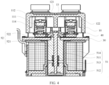
FIG. 4 is a schematic diagram of a cross section of a direct current contactor according to an embodiment of this application; -
FIG. 5 is a schematic diagram of a structure of an arc-extinguishing cavity in a direct current contactor according to an embodiment of this application; -
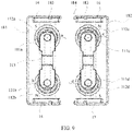
FIG. 6 is a schematic diagram of a cross section of an arc-extinguishing cavity in a direct current contactor according to an embodiment of this application; -
FIG. 7 is a schematic diagram of disposing two groups of contact components and magnets in a direct current contactor according to an embodiment of this application; -
FIG. 8 is a schematic diagram of an arc-blow principle of a direct current contactor during forward break according to an embodiment of this application; -
FIG. 9 is a schematic diagram of an arc-blow principle of a direct current contactor during reverse break according to an embodiment of this application; -
FIG. 10 is a schematic diagram of disposing a housing and a mounting bracket in a direct current contactor according to an embodiment of this application; -
FIG. 11 is a schematic diagram of cross sections of a housing and a mounting bracket in a direct current contactor according to an embodiment of this application; and -
FIG. 12 is a schematic diagram of disposing a moving component and a contact component in a direct current contactor according to an embodiment of this application. - Description of reference numerals:
100-direct current contactor; 10-case; 11-contact component; 11a-first group of contact component; 11b-second group of contact component; 111-moving contact; 111a-first moving contact; 111b-second moving contact; 111c-third moving contact; 111d-fourth moving contact; 112-fixed contact; 112a-first fixed contact; 112b-second fixed contact; 112c-third fixed contact; 112d-fourth fixed contact; 113-moving contact bridge; 114-elastic component; 115-fixed bracket; 12-arc-extinguishing cavity; 121-first arc-extinguishing chamber; 1211-fifth protrusion; 122-second arc-extinguishing chamber; 1221-sixth protrusion; 13-first baffle; 131-third protrusion; 132-fourth protrusion; 14-first magnet; 15-second magnet; 16-third magnet; 17-fourth magnet; 18-mounting bracket; 181-first bracket; 182-second bracket; 183-first clamping member; 184-second clamping member; 19-hole; 20-housing; 21-first protrusion; 22-second protrusion; 30-base plate; 40-connecting piece; 50-drive system; 51-drive component; 511-fixed iron core; 512-moving iron core; 513-reset spring; 514-electromagnetic coil; 52-moving component; 521-support rod; 522-moving plate; 5221-second baffle; 5222-groove; 5223-boss; 5224-third clamping member; and 53-drive chamber. - The terms used in implementations of this application are merely used to explain specific embodiments of this application, but are not intended to limit this application. The following describes in detail implementations of embodiments of this application with reference to the accompanying drawings.
- Currently, electric vehicles, as environmental-friendly and energy-saving vehicles, are increasingly widely used, and fast charging contactors that used with the electric vehicles are also widely used. A direct current contactor has become an important power distribution control component in a direct current charging circuit of the electric vehicle. In a current direct current fast charging circuit, an electric vehicle and a direct current fast charging apparatus are used as an example. Referring to
FIG. 1 , aPDU 500 and a high-voltage battery pack 200 connected to thePDU 500 are disposed in the electric vehicle. The charging apparatus of the electric vehicle has two wiring terminals: PIN1 and PIN2. PIN1 is a positive terminal, and PIN2 is a negative terminal. The terminal PIN1 is connected to thePDU 500 by using one directcurrent contactor 400, thePDU 500 is connected to a positive electrode of the high-voltage battery pack 200, and the terminal PIN2 is connected to a negative electrode of the high-voltage battery pack 200 by using one directcurrent contactor 400. During use, a connection between the direct currentfast charging apparatus 300 and the high-voltage battery pack 200 is controlled by controlling the two direct current contactors to be connected or disconnected. In the foregoing direct current fast charging circuit, one direct current contactor needs to be connected to each of the terminal PIN1 and the terminal PIN2. Consequently, the entire charging apparatus has a relatively large volume, occupies relatively large space, and has relatively high costs. In addition, when the two direct current contactors are separately disposed, it is also difficult to simultaneously disconnect or connect a positive line and a negative line. - To reduce the volume and the costs of the charging apparatus, in a conventional technology, there is also a design in which two contactors are integrated. For example, two single contactors are used to independently control the positive line and the negative line, and then the two single contactors are integrally encapsulated and integrated. Specifically, the contactor includes two cavities, each cavity has one contactor, and each contactor includes one moving contact, one fixed contact, and one electromagnetic drive mechanism. One group of control lines is used to simultaneously control the two electromagnetic drive mechanisms to drive the moving contact to be connected to or disconnected from the fixed contact. However, a volume of the contactor is still relatively large and needs to be further reduced, and manufacture costs are also relatively high. Consequently, a low-cost and lightweight requirement of a new energy vehicle cannot be met.
- Based on the foregoing technical problem, embodiments of this application provide a direct current contactor. The direct current contactor may be used for an electrical connection such as a connection between an electric vehicle and a direct current fast charging apparatus or a connection between another electric cabinet and an electrical device. In the direct current contactor, a single drive manner is used to form two arc-extinguishing chambers in one arc-extinguishing cavity to accommodate two groups of contact components, so as to implement a dual connection between the contactor and both a positive line and a negative line, so that a structure of the direct current contactor is simplified. In addition, there is no need to dispose one contactor on each of the positive line and the negative line, so that a volume of the charging apparatus is significantly reduced, and costs are reduced.
- The following specifically describes the direct current contactor by using an example in which the direct current contactor is used for the connection between the electric vehicle and the direct current fast charging apparatus.
- Referring to
FIG. 2 , this application provides a directcurrent contactor 100, including acase 10 and two groups ofcontact components 11 disposed in thecase 10. Each group ofcontact component 11 includes two movingcontacts 111 connected to each other and two fixedcontacts 112 opposite to the two movingcontacts 111. The fixedcontacts 112 extend outside thecase 10, so that the fixedcontacts 112 are connected to a positive line or a negative line. - Specifically, referring to
FIG. 3 , the two groups ofcontact components 11 in thecase 10 are respectively a first group of contact component 11a and a second group ofcontact component 11b. The first group of contact component 11a includes a first movingcontact 111a, a second movingcontact 111b connected to the first movingcontact 111a, and a first fixedcontact 112a and a secondfixed contact 112b that are respectively opposite to the first movingcontact 111a and the second movingcontact 111b. The second group ofcontact component 11b includes a third movingcontact 111c, a fourth movingcontact 111d connected to the third movingcontact 1 1 1c, and a thirdfixed contact 112c and a fourth fixedcontact 112d that are respectively opposite to the third movingcontact 111c and the fourth movingcontact 11 1d. The first group of contact component 11a and the second group ofcontact component 1 1b are parallel, the first movingcontact 111a and the third movingcontact 111c are adjacent, and the second movingcontact 111b and the fourth movingcontact 111d are adjacent. - Four connecting busbars may be disposed on the
case 10, and are respectively a first connecting busbar A1, a second connecting busbar A2, a third connecting busbar B1, and a fourth connecting busbar B2. The first connecting busbar A1 and the second connecting busbar A2 are respectively connected to the first fixedcontact 112a and the secondfixed contact 112b. The third connecting busbar B1 and the fourth connecting busbar B2 are respectively connected to the thirdfixed contact 112c and the fourth fixedcontact 112d. A fifth connecting busbar C1 and a sixth connecting busbar C2 may be further disposed on thecase 10, to electrically connect adrive system 50. - When the direct
current contactor 100 is used in a direct current fast charging circuit, the first connecting busbar A1 may be connected to a terminal PIN1, the third connecting busbar B1 may be connected to a terminal PIN2, the second connecting busbar A2 is connected to a positive electrode of a high-voltage battery pack, and the fourth connecting busbar B2 is connected to a negative electrode of the high-voltage battery pack, that is, the first connecting busbar A1 and the second connecting busbar A2 are a positive circuit, and the third connecting busbar B1 and the fourth connecting busbar B2 are a negative circuit. When the first movingcontact 111a is in electrical contact with the first fixedcontact 112a, and the second movingcontact 111b is in electrical contact with the secondfixed contact 112b, the first connecting busbar A1 is connected to the second connecting busbar A2. After passing through the first connecting busbar A1 from the terminal PIN1, a current sequentially passes through the first fixedcontact 112a, the first movingcontact 111a, the second movingcontact 1 1 1b, the secondfixed contact 112b, and the second connecting busbar A2, and then flows into the positive electrode of the high-voltage battery pack. - When the third moving
contact 111c is in electrical contact with the thirdfixed contact 112c, and the fourth movingcontact 111d is in electrical contact with the fourth fixedcontact 112d, the third connectingbusbar B 1 is connected to the fourth connecting busbar B2. A current flows from the positive electrode of the high-voltage battery pack into the fourth connecting busbar B2 through the negative electrode of the high-voltage battery pack, then sequentially passes through the fourth fixedcontact 112d, the fourth movingcontact 111d, the third movingcontact 111c, the thirdfixed contact 112c, and the third connecting busbar B1, and then flows into the terminal PIN2, to form a circuit. The moving contacts and the fixed contacts of the first group of contact component 11a may be controlled to be connected to or disconnected from each other, to control the positive line to be connected/disconnected, and the moving contacts and the fixed contacts of the second group ofcontact component 11b may be controlled to be connected to or disconnected from each other, to control the negative line to be connected/disconnected. - To be specific, in this embodiment of this application, connection/disconnection requirements of the positive line and the negative line can be met by using one direct
current contactor 100, and there is no need to mount one direct current contactor on each of the positive line and the negative of the charging apparatus. This simplifies a structural design of the charging apparatus, significantly reduces a volume of the charging apparatus, and reduces costs of the charging apparatus. - In this embodiment of this application, alternatively, the first connecting busbar A1 may be connected to the terminal PIN2, and the third connecting
busbar B 1 may be connected to the terminal PIN1. Break of the movingcontacts 111 and the fixedcontacts 112 in thecontact component 11 when the first connecting busbar A1 is connected to the terminal PIN1 is used as forward break, and break of the movingcontacts 111 and the fixedcontacts 112 in thecontact component 11 when the first connecting busbar A1 is connected to the terminal PIN2 is used as reverse break. - Specifically, referring to
FIG. 3 , thecase 10 has an arc-extinguishingcavity 12, and afirst baffle 13 is disposed in the arc-extinguishingcavity 12. As shown inFIG. 2 , thefirst baffle 13 divides the arc-extinguishingcavity 12 into a first arc-extinguishingchamber 121 and a second arc-extinguishingchamber 122, and the two groups ofcontact components 11 are respectively disposed in the first arc-extinguishingchamber 121 and the second arc-extinguishingchamber 122. An arc is generated in a process in which the movingcontacts 111 and the fixedcontacts 112 in thecontact component 11 are connected to or disconnected from each other. Thefirst baffle 13 plays a role of blocking the first arc-extinguishingchamber 121 and the second arc-extinguishingchamber 122, and may prevent arcs in the two arc-extinguishing chambers from being in contact with each other, reduce a risk of a short circuit, and improve break performance of the directcurrent contactor 100. - In addition, one arc-extinguishing
cavity 12 is divided into two arc-extinguishing chambers, to respectively dispose the two groups ofcontact components 11. Compared with an existing manner in which two contactors are integrally encapsulated, this manner can simplify a structural design of the contactor, reduce a size of the contactor, and reduce a volume of the charging apparatus. - The direct
current contactor 100 further includes adrive system 50. Thedrive system 50 is connected to the movingcontacts 111 of the two groups ofcontact components 11. Thedrive system 50 is configured to drive the movingcontacts 111 to move in a direction close to or away from the fixedcontacts 112, so that the fixedcontacts 112 are disconnected from or connected to the movingcontacts 111, to control the positive line and the negative line to be connected/disconnected. - In this embodiment of this application, the
single drive system 50 is used to drive the movingcontacts 111 of the two groups ofcontact components 11 to move, so that the positive line and the negative line are connected/disconnected. Compared with an existing manner in which two contactors are integrally encapsulated, a single drive manner can simplify a structural design of the contactor, reduce a size of the contactor, and reduce a volume of the charging apparatus. In addition, the two groups ofcontact components 11 are simultaneously driven by using onedrive system 50, so that connection/disconnection synchronization between the two groups ofcontact components 11 can be improved, to improve connection/disconnection synchronization between the positive line and the negative line in the charging apparatus, and improve reliability of the charging apparatus. - Referring to
FIG. 5 , in this embodiment of this application, afirst magnet 14 and asecond magnet 15 are respectively disposed on two sides that are outside the first arc-extinguishingchamber 121 and that are adjacent to the two movingcontacts 111. Specifically, thefirst magnet 14 is adjacent to the first movingcontact 111a, thesecond magnet 15 is adjacent to the second movingcontact 111b, thefirst magnet 14 and thesecond magnet 15 attract each other to form a first magnetic field, and thefirst magnet 14 and thesecond magnet 15 are opposite to gaps between the movingcontacts 111 and the fixedcontacts 112. Thefirst magnet 14 and thesecond magnet 15 are configured to extinguish arcs generated between the movingcontacts 111 and the fixedcontacts 112 in the first group of contact component 11a. - Specifically, referring to
FIG. 8 , when the movingcontacts 111 are connected to or disconnected from the fixedcontacts 112, arcs are generated at gaps at which the movingcontacts 111 are connected to or disconnected from the fixedcontacts 112, and the arc is blown into the first arc-extinguishingchamber 121 under magnetic field force of the first magnetic field, so that the arc is prolonged and extinguished in the first arc-extinguishingchamber 121. - A magnetic field direction of the first magnetic field is perpendicular to directions of currents flowing through the fixed
contacts 112 and the movingcontacts 111. Referring toFIG. 8 , an example in which the first connecting busbar A1 is connected to the terminal PIN1 is used. In this case, a direction of a current flowing through the first fixedcontact 112a and the first movingcontact 111a is a direction pointing from the first fixedcontact 112a to the first movingcontact 111a. As shown inFIG. 8 , the direction of the current is outward (towards the outside of paper). A current flowing through the secondfixed contact 112b and the second movingcontact 111b is inward (towards the inside of paper). An end that is of thefirst magnet 14 and that is close to the first movingcontact 111a is the S pole, and an end that is of thesecond magnet 15 and that is close to the second movingcontact 111b is the N pole. In other words, the direction of the first magnetic field is an upward direction shown inFIG. 8 , and points from thesecond magnet 15 to thefirst magnet 14. According to the left-hand rule, it may be learned that an arc between the first movingcontact 111a and the first fixedcontact 112a is blown to the left (namely, a direction of a in the figure) shown inFIG. 8 under the magnetic field force, and an arc between the second movingcontact 111b and the secondfixed contact 112b is blown to the right (namely, a direction of b in the figure) under the magnetic field force, so that the arc is blown into the first arc-extinguishing chamber and extinguished. - Referring to
FIG. 5 , athird magnet 16 and afourth magnet 17 are respectively disposed on two sides that are outside the second arc-extinguishingchamber 122 and that are adjacent to the two movingcontacts 111. Specifically, thethird magnet 16 is adjacent to the third movingcontact 111c, thefourth magnet 17 is adjacent to the fourth movingcontact 111d, thethird magnet 16 and thefourth magnet 17 attract each other to form a second magnetic field, and thethird magnet 16 and thefourth magnet 17 are opposite to gaps between the movingcontacts 111 and the fixedcontacts 112. Thethird magnet 16 and thefourth magnet 17 are configured to extinguish arcs generated between the movingcontacts 111 and the fixedcontacts 112 in the second group ofcontact component 11b. - Specifically, referring to
FIG. 8 , when the third movingcontact 111c is connected to or disconnected from the thirdfixed contact 112c, and the fourth movingcontact 111d is connected to or disconnected from the fourth fixedcontact 112d, arcs are generated at gaps at which the moving contacts are connected to or disconnected from the fixed contacts, and the arc is blown into the second arc-extinguishingchamber 122 under magnetic field force of the second magnetic field, so that the arc is prolonged and extinguished in the second arc-extinguishingchamber 122. - A magnetic field direction of the second magnetic field is perpendicular to directions of currents flowing through the fixed
contacts 112 and the movingcontacts 111. As shown inFIG. 8 , a current flowing through the thirdfixed contact 112c and the third movingcontact 111c is inward, and a current flowing through the fourth fixedcontact 112d and the fourth movingcontact 111d is outward. An end that is of thethird magnet 16 and that is close to the third movingcontact 111c is the N pole, and an end that is of thefourth magnet 17 and that is close to the fourth movingcontact 111d is the S pole, in other words, the direction of the second magnetic field is a downward direction shown inFIG. 8 , and points from thethird magnet 16 to thefourth magnet 17. According to the left-hand rule, it may be learned that an arc between the third movingcontact 111c and the thirdfixed contact 112c is blown to the left (namely, a direction of c in the figure) shown inFIG. 8 under the magnetic field force, and an arc between the fourth movingcontact 111d and the fourth fixedcontact 112d is blown to the right (namely, a direction of d in the figure) under the magnetic field force, so that the arc is blown into the second arc-extinguishing chamber and extinguished. - The first connecting busbar A1 may be connected to the terminal PIN2. In this case, a direction of a current flowing through the first fixed
contact 112a and the first movingcontact 111a is a direction pointing from the first movingcontact 111a to the first fixedcontact 112a. As shown inFIG. 9 , the direction of the current is inward. A direction of a current flowing through the secondfixed contact 112b and the second movingcontact 111b is outward. The direction of the first magnetic field is still upward, and points from thesecond magnet 15 to thefirst magnet 14. According to the left-hand rule, it may be learned that an arc between the first movingcontact 111a and the first fixedcontact 112a is blown to the right (namely, a direction of a in the figure) under the magnetic field force, and an arc between the second movingcontact 111b and the secondfixed contact 112b is blown to the left (namely, a direction of b in the figure), so that the arc is blown into the first-extinguishingchamber 121 and extinguished. - A current flowing through the third
fixed contact 112c and the third movingcontact 111c is outward, a current flowing through the fourth fixedcontact 112d and the fourth movingcontact 111d is inward, and the direction of the second magnetic field points from thethird magnet 16 to thefourth magnet 17. Referring toFIG. 9 , according to the left hand rule, it may be learned that an arc between the third movingcontact 111c and the thirdfixed contact 112c is blown to the right (namely, a direction of c in the figure) under the magnetic field force, and an arc between the fourth movingcontact 111d and the fourth fixedcontact 112d is blown to the left (namely, a direction of d in the figure) under the magnetic field force, so that the arc is blown into the second arc-extinguishing chamber and extinguished. In other words, in the directcurrent contactor 100 in this embodiment of this application, forward break and reverse break of two arcs can be implemented without a polarity requirement, and non-polarity arc extinguishing of the two groups of contact components can be implemented. - In this embodiment of this application, the magnetic field direction of the first magnetic field is opposite to the magnetic field direction of the second magnetic field. Under an action of the first magnetic field and the second magnetic field, arc-blow directions between the moving
contacts 111 and the fixedcontacts 112 in the first arc-extinguishingchamber 121 may be the same as arc-blow directions between the movingcontacts 111 and the fixedcontacts 112 that are in the second arc-extinguishingchamber 122 and that are adjacent to the movingcontacts 111 and the fixedcontacts 112 in the first arc-extinguishingchamber 121. For example, an arc-blow direction between the first movingcontact 111a and the first fixedcontact 112a is the same as an arc-blow direction between the third movingcontact 111c and the thirdfixed contact 112c, and an arc-blow direction between the second movingcontact 111b and the fixedcontact 112b is the same as an arc-blow direction between the fourth movingcontact 111d and the fourth fixedcontact 112d. Therefore, the two arcs generated by the first group of contact component 11a and the second group ofcontact component 11b do not move in a direction opposite to each other during forward break and reverse break. This reduces a risk of arc collision, arc aggregation, and a short circuit, and effectively improves break performance. - Specifically, referring to
FIG. 8 , the current flowing through the first fixedcontact 112a and the first movingcontact 111a is outward, the current flowing through the secondfixed contact 112b and the second movingcontact 111b is inward, the direction of the first magnetic field is upward and points from thesecond magnet 15 to thefirst magnet 14, the arc-blow direction between the first movingcontact 111a and the first fixedcontact 112a is leftward, and the arc-blow direction between the second movingcontact 111b and the secondfixed contact 112b is rightward. The current flowing through the thirdfixed contact 112c and the third movingcontact 111c is inward, the current flowing through the fourth fixedcontact 112d and the fourth movingcontact 111d is outward, the direction of the second magnetic field is opposite to the direction of the first magnetic field, the direction of the second magnetic field is downward and points from thethird magnet 16 to thefourth magnet 17, the arc-blow direction between the third movingcontact 111c and the thirdfixed contact 112c is leftward, and the arc-blow direction between the fourth movingcontact 111d and the fourth fixedcontact 112d is rightward. In other words, the arc-blow direction between the first movingcontact 111a and the first fixedcontact 112a is the same as the arc-blow direction between the third movingcontact 111c and the thirdfixed contact 112c that are adjacent to the first movingcontact 111a and the first fixedcontact 112a, and the arc-blow direction between the second movingcontact 111b and the secondfixed contact 112b is the same as the arc-blow direction between the fourth movingcontact 111d and the fourth fixedcontact 112d that are adjacent to the second movingcontact 111b and the secondfixed contact 112b. In this way, it is ensured that there is no collision between the two arcs during forward break, to effectively improve break performance of the contactor. - Referring to
FIG. 9 , the current flowing through the first fixedcontact 112a and the first movingcontact 111a is inward, the current flowing through the secondfixed contact 112b and the second movingcontact 111b is outward, the direction of the first magnetic field is upward and points from thesecond magnet 15 to thefirst magnet 14, the arc-blow direction between the first movingcontact 111a and the first fixedcontact 112a is rightward, and the arc-blow direction between the second movingcontact 111b and the secondfixed contact 112b is leftward. The current flowing through the thirdfixed contact 112c and the third movingcontact 111c is outward, the current flowing through the fourth fixedcontact 112d and the fourth movingcontact 111d is inward, the direction of the second magnetic field is downward and points from thethird magnet 16 to thefourth magnet 17, the arc-blow direction between the third movingcontact 111c and the thirdfixed contact 112c is rightward, and the arc-blow direction between the fourth movingcontact 111d and the fourth fixedcontact 112d is leftward. In other words, the arc-blow direction between the first movingcontact 111a and the first fixedcontact 112a is the same as the arc-blow direction between the third movingcontact 111c and the thirdfixed contact 112c that are adjacent to the first movingcontact 111a and the first fixedcontact 112a, and the arc-blow direction between the second movingcontact 111b and the secondfixed contact 112b is the same as the arc-blow direction between the fourth movingcontact 111d and the fourth fixedcontact 112d that are adjacent to the second movingcontact 111b and the secondfixed contact 112b. In this way, it is ensured that there is no collision between the two arcs during reverse break, to effectively improve break performance of the directcurrent contactor 100. - In this embodiment of this application, a material used to form the
case 10 may be a magnetic conductive material such as a ceramic, and may play a role of shielding an external magnetic field. However, thefirst baffle 13 in thecase 10 may be formed through protrusion on an inner top wall of thecase 10, thefirst baffle 13 and thecase 10 may be integrally formed, and thefirst baffle 13 may prevent arcs blowing into the first arc-extinguishingchamber 121 and the second arc-extinguishingchamber 122 from being in contact with each other, to further improve break performance of the directcurrent contactor 100. - The direct
current contactor 100 further includes a mountingbracket 18. Referring toFIG. 5 , the mountingbracket 18 includes afirst bracket 181 and asecond bracket 182 that are opposite to each other. Thefirst bracket 181 and thesecond bracket 182 are disposed around a periphery of thecase 10. Thefirst magnet 14 and thesecond magnet 15 are disposed on an inner side wall of thefirst bracket 181. Thethird magnet 16 and thefourth magnet 17 are disposed on an inner side wall of thesecond bracket 182. In other words, thefirst bracket 181 is located on a periphery of the first arc-extinguishingchamber 121, and thesecond bracket 182 is located on a periphery of the second arc-extinguishingchamber 122. Thefirst magnet 14 and thesecond magnet 15 are disposed outside thefirst extinguishing chamber 121 by using thefirst bracket 181, and thethird magnet 16 and thefourth magnet 17 are disposed outside the second arc-extinguishingchamber 122 by using thesecond bracket 182. - The
first bracket 181 and thesecond bracket 182 may be U-shaped brackets. Referring toFIG. 11 , a side wall of the U-shaped bracket has afirst clamping member 183, an end of an opening of the U-shaped bracket has asecond clamping member 184 protruding towards the inside of the opening, and at least one of thefirst magnet 14, thesecond magnet 15, thethird magnet 16, and thefourth magnet 17 is disposed on the U-shaped bracket by using thefirst clamping member 183 and thesecond clamping member 184. In other words, thefirst magnet 14, thesecond magnet 15, thethird magnet 16, and thefourth magnet 17 are disposed on thefirst bracket 181 and thesecond bracket 182 through clamping. This can facilitate assembly, disassembly, and replacement. - The
first clamping member 183 may be a clamping jaw, a clamping slot, or another clamping member that is disposed on an outer wall of a side of the U-shaped bracket, and thesecond clamping member 184 may also be a clamping jaw, a clamping slot, or another clamping member that is formed after the end of the opening protrudes towards the inside. - The
first bracket 181 and thesecond bracket 182 may be magnetic conductive plates with magnetic conductive performance. Thefirst bracket 181 and thesecond bracket 182 are disposed around the periphery of thecase 10. Specifically, thefirst bracket 181 may be disposed around on the periphery of the first arc-extinguishingchamber 121, and thesecond bracket 182 may be disposed on the periphery of the second arc-extinguishingchamber 122, so that thefirst bracket 181 and thesecond bracket 182 are magnetic conductive plates such as metal brackets, and can play a role of shielding the external magnetic field, to improve arc-extinguishing performance of the first arc-extinguishingchamber 121 and the second arc-extinguishingchamber 122, and improve break performance of the directcurrent contactor 100. - In this embodiment of this application, the
first magnet 14, thesecond magnet 15, thethird magnet 16, and thefourth magnet 17 may be permanent magnets, have relatively strong magnetism, and are not easy to be demagnetized, so that the magnetic field force of the first magnetic field and the second magnetic field can be ensured, and arc-blow and arc-extinguishing effects are ensured. In addition, the magnet has a relatively long service life, to help improve reliability of the directcurrent contactor 100. - Referring to
FIG. 10 , the directcurrent contactor 100 further includes ahousing 20, and the mountingbracket 18 is located in thehousing 20. Referring toFIG. 7 , a side or a corner of the at least one of thefirst magnet 14, thesecond magnet 15, thethird magnet 16, and thefourth magnet 17 has ahole 19. As shown inFIG. 10 , an inner side wall of thehousing 20 has afirst protrusion 21 corresponding to thehole 19. When magnetic poles of thefirst magnet 14, thesecond magnet 15, thethird magnet 16, and thefourth magnet 17 are reversely or incorrectly mounted, because thehole 19 and thefirst protrusion 21 are disposed, thefirst bracket 181 on which thefirst magnet 14 and thesecond magnet 15 are disposed and thesecond bracket 182 on which thethird magnet 16 and thefourth magnet 17 are disposed cannot be assembled in thecase 10. This can effectively avoid a problem that thefirst magnet 14, thesecond magnet 15, thethird magnet 16, and thefourth magnet 17 are reversely or incorrectly mounted, and improve assembly accuracy and assembly efficiency. - Referring to
FIG. 10 , in a possible implementation, thehousing 20 is buckled on thecase 10, and thefirst clamping member 183 is adjacent to the movingcontact 111. In other words, thefirst clamping member 183 is located on an outer side wall of an end that is of the U-shaped bracket and that is close to the movingcontact 111. When thefirst magnet 14, thesecond magnet 15, thethird magnet 16, and thefourth magnet 17 are disposed on the U-shaped bracket by using thefirst clamping member 183, a side that is of the magnet and that is close to the fixedcontact 112 is not limited. Consequently, there is a slip risk. In this embodiment of this application, an inner wall of an end that is of thehousing 20 and that is adj acent to the fixedcontact 112 has asecond protrusion 22. A side wall of the at least one of thefirst magnet 14, thesecond magnet 15, thethird magnet 16, and thefourth magnet 17 abuts against a side wall of thesecond protrusion 22. In this way, a position of the magnet is further limited by using thesecond protrusion 22. Thefirst clamping member 183, thesecond clamping member 184, and thesecond protrusion 22 jointly limit the magnet, to prevent the magnet from falling off the U-shaped bracket, and improve disposition stability of the magnet. - In this embodiment of this application, referring to
FIG. 2 , the directcurrent contactor 100 further includes abase plate 30. Thecase 10 covers thebase plate 30. Thecase 10 and thebase plate 30 surround the arc-extinguishingcavity 12. Specifically, thebase plate 30 and thecase 10 may surround a sealed arc-extinguishingcavity 12. Thebase plate 30 may also be a magnetic conductive plate with magnetic conductive performance such as a ceramic, so that the external magnetic field can be shielded. - The
case 10 and thebase plate 30 may be connected through welding, bonding, clamping and fastening, and the like. Thecase 10 and thebase plate 30 may be directly connected, or thecase 10 and thebase plate 30 may be indirectly connected. For example, in a possible implementation, referring toFIG. 2 , thecase 10 and thebase plate 30 are connected by using a connectingpiece 40. Specifically, thecase 10 and thebase plate 30 may be connected through welding by using ametal connecting piece 40. Compared with a manner in which thecase 10 and thebase plate 30 are directly connected, in a manner of implementing a connection by using the connectingpiece 40, a problem that thecase 10 and thebase plate 30 are deformed, are separated, and fall off in a high temperature may be reduced, to improve reliability of the directcurrent contactor 100. - In this embodiment of this application, referring to
FIG. 5 , a side wall that is of thefirst baffle 13 and that faces the first arc-extinguishingchamber 121 has athird protrusion 131, and one side wall of thefirst baffle 13 is used as a side wall of the first arc-extinguishingchamber 121. Under an action of the first magnetic field, the arc between the first movingcontact 111a and the first fixedcontact 112a or between the second movingcontact 111b and the secondfixed contact 112b is blown to the side wall. Because thethird protrusion 131 is disposed on the side wall, a length of the side wall is increased, and a creepage distance between the first movingcontact 111a and the first fixedcontact 112a, and the second movingcontact 111b and the secondfixed contact 112b is increased. This helps extinguish the arc in a timely manner, saves space required for arc extinguishing, further improves break performance of the directcurrent contactor 100, and helps reduce a volume of the directcurrent contactor 100. - Referring to
FIG. 5 , a side wall that is of thefirst baffle 13 and that faces the second arc-extinguishingchamber 122 has afourth protrusion 132, and the other side wall of thefirst baffle 13 is used as a side wall of the second arc-extinguishingchamber 122. Under an action of the second magnetic field, the arc between the third movingcontact 111c and the thirdfixed contact 112c or between the fourth movingcontact 111d and the fourth fixedcontact 112d is blown to the side wall. Because thefourth protrusion 132 is disposed on the side wall, similarly, a length of the side wall is increased, and a creepage distance between the third movingcontact 111c and the thirdfixed contact 112c, and the fourth movingcontact 111d and the fourth fixedcontact 112d is increased. This helps extinguish the arc in a timely manner, saves space required for arc extinguishing, and further improves break performance of the directcurrent contactor 100. - There may be one
third protrusion 131 and onefourth protrusion 132, or there may be a plurality ofthird protrusions 131 and a plurality offourth protrusions 132. As shown inFIG. 5 , there may be twothird protrusions 131 and twofourth protrusions 132. The twothird protrusions 131 divide the first arc-extinguishingchamber 121 into three layers shown inFIG. 5 . The first movingcontact 111a and the first fixedcontact 112a, and the second movingcontact 111b and the secondfixed contact 112b are respectively located at two layers at ends. The twofourth protrusions 132 divide the second arc-extinguishingchamber 122 into three layers. The third movingcontact 111c and the thirdfixed contact 112c, and the fourth movingcontact 111d and the fourth fixedcontact 112d are respectively located at two layers at ends. - Referring to
FIG. 5 , a side wall that is of the first arc-extinguishingchamber 121 and that is opposite to thefirst baffle 13 may have afifth protrusion 1211. Under an action of the first magnetic field, the arc between the first movingcontact 111a and the first fixedcontact 112a or between the second movingcontact 111b and the secondfixed contact 112b in the first arc-extinguishingchamber 121 may be blown to the side wall. Because thefifth protrusion 1211 is disposed on the side wall, a length of the side wall may be increased, and the creepage distance between the first movingcontact 111a and the first fixedcontact 112a, and the second movingcontact 111b and the secondfixed contact 112b may be increased. This helps extinguish the arc in a timely manner, saves space required for arc extinguishing, and further improves break performance of the directcurrent contactor 100. - A side wall that is of the second arc-extinguishing
chamber 122 and that is opposite to thefirst baffle 13 may have asixth protrusion 1221. Under an action of the second magnetic field, the arc between the third movingcontact 111c and the thirdfixed contact 112c or between the fourth movingcontact 111d and the fourth fixedcontact 112d is blown to the side wall. Because thesixth protrusion 1221 exists on the side wall, similarly, a length of the side wall is increased, and the creepage distance between the third movingcontact 111c and the thirdfixed contact 112c, and the fourth movingcontact 111d and the fourth fixedcontact 112d is increased. This helps extinguish the arc in a timely manner, saves space required for arc extinguishing, and further improves break performance of the directcurrent contactor 100. - In this embodiment of this application, the
drive system 50 includes adrive component 51 and a movingcomponent 52. Referring toFIG. 4 , the movingcomponent 52 includes asupport rod 521 and a movingplate 522 connected to thesupport rod 521. The movingplate 522 is located in the arc-extinguishingcavity 12, and the movingcontacts 111 of the two groups ofcontact components 11 are disposed on the movingplate 522. In other words, the first movingcontact 111a, the second movingcontact 111b, the third movingcontact 111c, and the fourth movingcontact 111d are disposed on the movingplate 522. The drivingcomponent 51 is configured to drive the movingcomponent 52 to move to drive the movingcontacts 111 to move. Specifically, the drivingcomponent 51 may drive thesupport rod 521 in the movingcomponent 52 to move up and down, and thesupport rod 521 drives the movingplate 522 to move, to drive the movingcontacts 111 on the movingplate 522 to move in the direction close to or away from the fixedcontacts 112, so that the movingcontacts 111 are connected to or disconnected from the fixedcontacts 112. - Referring to
FIG. 12 , the movingplate 522 is a plate-like structure with an area. Compared with an existing manner in which the moving contacts are disposed on a connecting rod, in this manner, the movingplate 522 may provide higher strength and have higher mechanical strength. This helps improve reliability of the directcurrent contactor 100. - The moving
plate 522 and thesupport rod 521 may be integrally formed, or thesupport rod 521 and the movingplate 522 may be separately disposed. Specifically, thesupport rod 521 and the movingplate 522 may be fastened and connected through thread-connection, welding, bonding, and the like. - In this embodiment of this application, when the moving
contacts 111 are disconnected from the fixedcontacts 112, there is a gap between thefirst baffle 13 and the movingplate 522. The gap provides space for the movingplate 522 to move, so as to ensure that the movingplate 522 can move to drive the movingcontacts 111 to move - Because there is a gap between the
first baffle 13 and the movingplate 522, an arc generated in one of the first arc-extinguishingchamber 121 and the second arc-extinguishingchamber 122 may appear in the other chamber through the gap, and a problem such as arc aggregation and a short circuit occurs. Therefore, in this embodiment of this application, referring toFIG. 6 , the movingplate 522 has asecond baffle 5221, and thesecond baffle 5221 is located on an outer side of the gap, to ensure that thesecond baffle 5221 does not affect movement of the movingplate 522. Thesecond baffle 5221 extends towards thefirst baffle 13, and thesecond baffle 5221 at least partially overlaps thefirst baffle 13. Specifically, an end that is of thesecond baffle 5221 and that faces thefirst baffle 13 partially overlaps an end that is of thefirst baffle 13 and that faces thesecond baffle 5221, so that thesecond baffle 5221 can cover the gap. In this way, sealing between the first arc-extinguishingchamber 121 and the second arc-extinguishingchamber 122 is further improved, a probability that the arcs in the first arc-extinguishingchamber 121 and the second arc-extinguishingchamber 122 are in contact with each other is further reduced, and break performance of the directcurrent contactor 100 is improved. - A plane on which the
first baffle 13 is located is used as a first plane. That thesecond baffle 5221 at least partially overlaps thefirst baffle 13 specifically means that a projection of thesecond baffle 5221 on the first plane at least partially overlaps thefirst baffle 13. - The
second baffle 5221 may be a baffle plate, or thesecond baffle 5221 may be a mechanical part with a baffle plate. The movingplate 522 may have onesecond baffle 5221, or may have a plurality ofsecond baffles 5221. - Specifically, referring to
FIG. 12 , agroove 5222 is disposed on the movingplate 522, a side wall of thegroove 5222 forms thesecond baffle 5221, and thefirst baffle 13 may extend into thegroove 5222. Specifically, when the movingplate 522 moves upwards to enable the movingcontacts 111 to be connected to the fixedcontacts 112, thefirst baffle 13 may extend into thegroove 5222. Thegroove 5222 has two side walls and one bottom wall connected to the two side walls. The two side walls of thegroove 5222 are used as twosecond baffles 5221, and the twosecond baffles 5221 and thefirst baffle 13 jointly isolate and separate the first arc-extinguishingchamber 121 and the second arc-extinguishingchamber 122. In addition, thegroove 5222 may be further disposed to increase a creepage distance between the first movingcontact 111a and the first fixedcontact 112a, and the third movingcontact 111c and the thirdfixed contact 112c, and a creepage distance between the second movingcontact 111b and the secondfixed contact 112b, and the fourth movingcontact 111d and the fourth fixedcontact 112d. This helps extinguish the arc in a timely manner, and improve break performance of the directcurrent contactor 100. - The
groove 5222 and the movingplate 522 may be integrally formed, or thegroove 5222 may be separately formed and then disposed on the movingplate 522. Thegroove 5222 and the movingplate 522 may be disposed through clamping, bonding, welding, thread-fastening, and the like. - In this embodiment of this application, an arc is generated at a position at which the moving
contact 111 is opposite to the fixedcontact 112, and an arc at a position at which two movingcontacts 111 are connected has a relatively small impact. Therefore, referring toFIG. 5 , thesecond baffle 5221 may be disposed only at each of positions that are on the movingplate 522 and that are opposite to the two movingcontacts 111, and nosecond baffle 5221 may be disposed at a position opposite to a position at which the movingcontacts 111 are connected. In this way, a structure of the movingcomponent 52 can be simplified, and costs can also be reduced. - Referring to
FIG. 2 , thedrive system 50 further includes adrive chamber 53, and thedrive component 51 is located in thedrive chamber 53. Referring toFIG. 4 , one end of thesupport rod 521 is located in thedrive chamber 53, and the other end of thesupport rod 521 extends into the arc-extinguishingcavity 12. Thedrive chamber 53 may be connected to thecase 10. Specifically, thedrive chamber 53 and thecase 10 may share thebase plate 30, in other words, thebase plate 30 is used as a side wall of thedrive chamber 53. Thebase plate 30 may have a through hole, and the other end of thesupport rod 521 may extend into the arc-extinguishingcavity 12 through the through hole. - In this embodiment of this application, referring to
FIG. 4 , thedrive component 51 may include a fixediron core 511 and a movingiron core 512 that are sleeved on thesupport rod 521. The fixediron core 511 is located at an end that is of thesupport rod 521 and that is close to thebase plate 30. The movingiron core 512 is located at an end that is of thesupport rod 521 and that is away from thebase plate 30. In addition, the movingiron core 512 is fastened and connected to thesupport rod 521, and the fixediron core 511 is fastened and connected to a case of thedrive chamber 53. There is a gap between the fixediron core 511 and the movingiron core 512. Areset spring 513 is disposed in the gap. Thereset spring 513 is sleeved on a periphery of thesupport rod 521, and one end of thereset spring 513 abuts against the movingiron core 512, and the other end of thereset spring 513 abuts against the fixediron core 511. Thedrive component 51 may further include anelectromagnetic coil 514 that surrounds the fixediron core 511 and the movingiron core 512. When theelectromagnetic coil 514 is powered on, the fixediron core 511 and the movingiron core 512 attract each other. - When the direct
current contactor 100 is used, theelectromagnetic coil 514 is powered on, the fixediron core 511 and the movingiron core 512 attract each other, and the fixediron core 511 is fastened in thedrive chamber 53. In this case, the movingiron core 512 moves towards the fixediron core 511 against elastic force of thereset spring 513, and drives thesupport rod 521 to move. Thesupport rod 521 drives the movingplate 522 to move, to drive the movingcontacts 111 on the movingplate 522 to move in the direction close to the fixedcontacts 112, so as to enable the movingcontacts 111 to be in electrical contact with the fixedcontacts 112, so that the movingcontacts 111 are connected to the fixedcontacts 112. When theelectromagnetic coil 514 is powered off, there is no magnetic attraction force between the fixediron core 511 and the movingiron core 512. Under an action of thereset spring 513, the movingiron core 512 moves away from the fixediron core 511, to drive thesupport rod 521 and the movingplate 522 to move, and drive the movingcontacts 111 to move in the direction away from the fixedcontacts 112, so as to enable the movingcontacts 111 to be separated from the fixedcontacts 112, so that the movingcontacts 111 are disconnected from the fixedcontacts 112. - Referring to
FIG. 7 , thecontact component 11 further includes a movingcontact bridge 113. The two movingcontacts 111 are connected to each other by using the movingcontact bridge 113. Specifically, the two movingcontacts 111 are located on two sides of the movingcontact bridge 113. Referring toFIG. 12 , thecontact component 11 further includes anelastic component 114. Theelastic component 114 is located between the movingcontact bridge 113 and the movingplate 522. Specifically, theelastic component 114 may be a spring. When the movingplate 522 moves to drive the movingcontacts 111 to move in the direction close to the fixedcontacts 112, the movingcontacts 111 first abut against the fixedcontacts 112. When the movingplate 522 continues to move, theelastic component 114 located between the movingplate 522 and the movingcontact bridge 113 is compressed, and the compressedelastic component 114 pushes the movingcontacts 111, so that the movingcontacts 111 are pressed against the fixedcontacts 112. This ensures reliable contact between the movingcontacts 111 and the fixedcontacts 112, and improves stability of a connection between the movingcontacts 111 and the fixedcontacts 112. - In an existing contactor, the moving
contact 111 and theelastic component 114 are connected through sleeving by using a shaft hole. Specifically, there is a connecting rod between the movingcontact 111 and the movingcomponent 52, one end of the connecting rod passes through the movingcontact 111 and is fastened to the movingcontact 111, and the other end of the connecting rod is fastened and connected to the movingcomponent 52. Theelastic component 114 is sleeved on the connecting rod. In the manner in which the movingcontact 111 and theelastic component 114 are connected through sleeving by using a shaft hole, a hole need to be provided on the movingcontact 111. Consequently, a conductive area of the movingcontact 111 is reduced, and a conductive capability is reduced. - In this application, referring to
FIG. 12 , thecontact component 11 may further include a U-shaped fixedbracket 115, the movingcontact bridge 113 and theelastic component 114 are located in the fixedbracket 115, theelastic component 114 is located between the movingcontact bridge 113 and the movingplate 522, and an opening end of the fixedbracket 115 is disposed on the movingplate 522. In this way, the movingcontact bridge 113 and theelastic component 114 are disposed on the movingplate 522 by using the fixedbracket 115, and no shaft hole needs to be provided on the movingcontact 111 and the movingcontact bridge 113. This avoids affecting a conductive area of thecontact component 11, ensures conductive performance of thecontact component 11, and helps improve a capability of thecontact component 11 to carry a current. - To further stabilize the
elastic component 114, a seventh protrusion (not shown) may be provided at each of positions that are on the movingplate 522 and the movingcontact bridge 113 and that correspond to theelastic component 114. Two ends of theelastic component 114 are respectively sleeved on peripheries of the seventh protrusions. The seventh protrusion may play a role of limiting and guiding theelastic component 114, so that theelastic component 114 is prevented from falling off between the movingcontact bridge 113 and the movingplate 522, and theelastic component 114 can also be prevented from being distorted and then being in capable of being compressed. - The fixed
bracket 115 may be disposed on the movingplate 522 through bonding, welding, clamping, thread-connection, and the like. Specifically, in this embodiment of this application, referring toFIG. 12 , the movingplate 522 may have aboss 5223 protruding from a plane on which the movingplate 522 is located. Theboss 5223 is configured to dispose thecontact component 11, and two opposite side walls of theboss 5223 each may have a protrudingthird clamping member 5224. The opening end of the fixedbracket 115 may have a clamping slot (not shown) that can match thethird clamping member 5224, and the opening end of the fixedbracket 115 may be clamped and fastened to the movingplate 522 through matching between the clamping slot and thethird clamping member 5224, to fasten the movingcontact 111 and theelastic component 114 to the movingplate 522 by using the fixedbracket 115. - An embodiment of this application further provides a vehicle, including at least any one of the foregoing direct
current contactors 100. The vehicle may be an electric vehicle (EV), a pure electric vehicle (PEV/BEV), a hybrid electric vehicle (HEV), a range extended electric vehicle (REEV), a plug-in hybrid electric vehicle (PHEV), a new energy vehicle, or the like. - The vehicle may further include a vehicle body and a power distribution unit disposed on the vehicle body, and the power distribution unit is connected to the direct
current contactor 100. The vehicle may further include a wheel, a motor, a drive component, and the like. - The vehicle provided in this embodiment of this application includes the direct
current contactor 100, and in the directcurrent contactor 100, a single drive manner is used to integrate two groups of contact components into one arc-extinguishing cavity, to implement a dual connection between the contactor and both a positive line and a negative line, so that a structure of the contactor is simplified. In addition, there is no need to dispose one contactor on each of the positive line and the negative line, so that a volume and manufacture costs of a charging apparatus are significantly reduced, and miniaturization is implemented, and a load capability is improved, to help implement a low-cost and lightweight requirement of the vehicle. - In the description of embodiments of this application, it should be noted that, unless otherwise clearly specified and limited, terms "assemble", "connected", and "connection" should be understood in a broad sense. For example, the terms may be used for a fixed connection, an indirect connection through an intermediate medium, an internal connection between two elements, or an interaction relationship between two elements. Persons of ordinary skill in the art may understand specific meanings of the terms in embodiments of this application based on specific cases.
- The terms "first", "second", "third", "fourth" and the like (if they exist) in the specification of embodiments of this application are used to distinguish similar objects, and do not need to be used to describe a specific order or sequence.
- Finally, it should be noted that the foregoing embodiments are merely intended for describing the technical solutions of embodiments of this application rather than limiting this application. Although embodiments of this application are described in detail with reference to the foregoing embodiments, persons of ordinary skill in the art should understand that they may still make modifications to the technical solutions described in the foregoing embodiments or make equivalent replacements to a part or all technical features thereof, without departing from the scope of the technical solutions of embodiments of this application.
Claims (20)
- A direct current contactor, comprising a case and two groups of contact components disposed in the case, wherein each group of contact components comprises two moving contacts connected to each other and two fixed contacts opposite to the moving contacts, and the fixed contacts extend outside the case;the case has an arc-extinguishing cavity, a first baffle is disposed in the arc-extinguishing cavity, the first baffle divides the arc-extinguishing cavity into a first arc-extinguishing chamber and a second arc-extinguishing chamber, and the two groups of contact components are respectively disposed in the first arc-extinguishing chamber and the second arc-extinguishing chamber; andthe direct current contactor further comprises a drive system, wherein the drive system is connected to the moving contacts of the two groups of contact components, and the drive system is configured to drive the moving contacts to move in a direction close to or away from the fixed contacts, so that the moving contacts are disconnected from or connected to the fixed contacts.
- The direct current contactor according to claim 1, wherein a first magnet and a second magnet are respectively disposed on two sides that are outside the first arc-extinguishing chamber and that are adjacent to the two moving contacts, the first magnet and the second magnet attract each other to form a first magnetic field, and the first magnet and the second magnet are opposite to gaps between the moving contacts and the fixed contacts;a third magnet and a fourth magnet are respectively disposed on two sides that are outside the second arc-extinguishing chamber and that are adjacent to the two moving contacts, the third magnet and the fourth magnet attract each other to form a second magnetic field, and the third magnet and the fourth magnet are opposite to gaps between the moving contacts and the fixed contacts; andmagnetic field directions of the first magnetic field and the second magnetic field are perpendicular to directions of currents flowing through the fixed contacts and the moving contacts, and the magnetic field direction of the first magnetic field is opposite to the magnetic field direction of the second magnetic field.
- The direct current contactor according to claim 2, further comprising a mounting bracket, wherein the mounting bracket comprises a first bracket and a second bracket that are opposite to each other, the first bracket and the second bracket are disposed around a periphery of the case, the first magnet and the second magnet are disposed on an inner side wall of the first bracket, and the third magnet and the fourth magnet are disposed on an inner side wall of the second bracket.
- The direct current contactor according to claim 3, wherein the first bracket and the second bracket are U-shaped brackets, a side wall of the U-shaped bracket has a first clamping member, an end of an opening of the U-shaped bracket has a second clamping member protruding towards the inside of the opening, and at least one of the first magnet, the second magnet, the third magnet, or the fourth magnet is disposed on the U-shaped bracket by using the first clamping member and the second clamping member.
- The direct current contactor according to claim 4, further comprising a housing, wherein the mounting bracket is located in the housing, a side or a corner of the at least one of the first magnet, the second magnet, the third magnet, and the fourth magnet has a hole, and an inner side wall of the housing has a first protrusion corresponding to the hole.
- The direct current contactor according to claim 5, wherein the first clamping member is adjacent to the moving contact, an inner wall of an end that is of the housing and that is adjacent to the fixed contact has a second protrusion, and a side wall of the at least one of the first magnet, the second magnet, the third magnet, and the fourth magnet abuts against a side wall of the second protrusion.
- The direct current contactor according to any one of claims 3 to 6, wherein the first bracket and the second bracket are magnetic conductive plates with magnetic conductive performance.
- The direct current contactor according to any one of claims 2 to 7, wherein the first magnet, the second magnet, the third magnet, and the fourth magnet are permanent magnets.
- The direct current contactor according to any one of claims 1 to 8, further comprising a base plate, wherein the case is disposed on the base plate, and the case and the base plate surround the arc-extinguishing cavity.
- The direct current contactor according to claim 9, wherein the case and the base plate are connected by using a connecting piece.
- The direct current contactor according to any one of claims 1 to 10, wherein a side wall that is of the first baffle and that faces the first arc-extinguishing chamber has a third protrusion, and a side wall that is of the first baffle and that faces the second arc-extinguishing chamber has a fourth protrusion.
- The direct current contactor according to any one of claims 1 to 11, wherein a side wall that is of the first arc-extinguishing chamber and that is opposite to the first baffle has a fifth protrusion, and a side wall that is of the second arc-extinguishing chamber and that is opposite to the first baffle has a sixth protrusion.
- The direct current contactor according to any one of claims 1 to 12, wherein the drive system comprises a drive component and a moving component, the moving component comprises a support rod and a moving plate connected to the support rod, the moving plate is located in the arc-extinguishing cavity, and the moving contacts of the two groups of contact components are disposed on the moving plate; and
the drive component is configured to drive the moving component to move to drive the moving contacts to move, and when the moving contacts are disconnected from the fixed contacts, there is a gap between the first baffle and the moving plate. - The direct current contactor according to claim 13, wherein the moving plate has a second baffle, the second baffle is located on an outer side of the gap, the second baffle extends towards the first baffle, and the second baffle at least partially overlaps the first baffle.
- The direct current contactor according to claim 14, wherein a groove is disposed on the moving plate, a side wall of the groove forms the second baffle, and the first baffle extends into the groove.
- The direct current contactor according to claim 15, wherein the second baffle is disposed at each of positions that are on the moving plate and that are opposite to the two moving contacts.
- The direct current contactor according to any one of claims 13 to 16, wherein the drive system further comprises a drive chamber, the drive component is located in the drive chamber, one end of the support rod is located in the drive chamber, and the other end of the support rod extends into the arc-extinguishing cavity.
- The direct current contactor according to any one of claims 13 to 17, wherein the contact component further comprises a moving contact bridge and an elastic component, the two moving contacts are connected by using the moving contact bridge, and the elastic component is located between the moving contact bridge and the moving plate.
- The direct current contactor according to claim 18, wherein the contact component further comprises a U-shaped fixed bracket, the moving contact bridge and the elastic component are located in the fixed bracket, and an opening end of the fixed bracket is disposed on the moving plate.
- A vehicle, comprising at least the direct current contactor according to any one of claims 1 to 19.
Applications Claiming Priority (2)
| Application Number | Priority Date | Filing Date | Title |
|---|---|---|---|
| CN202010591488.5A CN111863538A (en) | 2020-06-24 | 2020-06-24 | Direct current contactor and vehicle |
| PCT/CN2021/093420 WO2021258895A1 (en) | 2020-06-24 | 2021-05-12 | Direct current contactor and vehicle |
Publications (2)
| Publication Number | Publication Date |
|---|---|
| EP4145485A1 true EP4145485A1 (en) | 2023-03-08 |
| EP4145485A4 EP4145485A4 (en) | 2023-09-20 |
Family
ID=72988163
Family Applications (1)
| Application Number | Title | Priority Date | Filing Date |
|---|---|---|---|
| EP21829112.8A Pending EP4145485A4 (en) | 2020-06-24 | 2021-05-12 | Direct current contactor and vehicle |
Country Status (4)
| Country | Link |
|---|---|
| US (1) | US20230098632A1 (en) |
| EP (1) | EP4145485A4 (en) |
| CN (1) | CN111863538A (en) |
| WO (1) | WO2021258895A1 (en) |
Families Citing this family (5)
| Publication number | Priority date | Publication date | Assignee | Title |
|---|---|---|---|---|
| CN111863538A (en) * | 2020-06-24 | 2020-10-30 | 华为技术有限公司 | Direct current contactor and vehicle |
| CN115249600A (en) * | 2021-04-27 | 2022-10-28 | 比亚迪股份有限公司 | Relay with a movable contact |
| CN115742782A (en) * | 2021-09-03 | 2023-03-07 | 比亚迪股份有限公司 | Contactor for vehicle, vehicle charging and distributing system, charging pile and vehicle |
| CN114188191A (en) * | 2021-10-29 | 2022-03-15 | 华为数字能源技术有限公司 | Power distribution module and vehicle |
| CN114792610A (en) * | 2022-04-02 | 2022-07-26 | 华为数字能源技术有限公司 | Power supply system and switch unit |
Family Cites Families (9)
| Publication number | Priority date | Publication date | Assignee | Title |
|---|---|---|---|---|
| JPH02250229A (en) * | 1989-03-24 | 1990-10-08 | Mitsubishi Electric Corp | Electromagnetic contactor |
| CN2337662Y (en) * | 1998-03-17 | 1999-09-08 | 桂林机床电器厂 | Double-pole AC contact with protective enclosure |
| JP2005332588A (en) * | 2004-05-18 | 2005-12-02 | Fuji Electric Fa Components & Systems Co Ltd | Electromagnetic contactor |
| US7868720B2 (en) * | 2007-11-01 | 2011-01-11 | Tyco Electronics Corporation India | Hermetically sealed relay |
| CN107331583A (en) * | 2017-08-15 | 2017-11-07 | 昆山国力源通新能源科技有限公司 | Nonpolarity high-voltage DC contactor arc quenching system structure |
| CN108922827A (en) * | 2018-07-26 | 2018-11-30 | 哈尔滨工业大学 | A kind of contact mechanism in four breakpoints contactor |
| US10483068B1 (en) * | 2018-12-11 | 2019-11-19 | Eaton Intelligent Power Limited | Switch disconnector systems suitable for molded case circuit breakers and related methods |
| CN210640160U (en) * | 2019-09-24 | 2020-05-29 | 上海为鹏科技有限公司 | Arc extinguishing structure of direct current contactor |
| CN111863538A (en) * | 2020-06-24 | 2020-10-30 | 华为技术有限公司 | Direct current contactor and vehicle |
-
2020
- 2020-06-24 CN CN202010591488.5A patent/CN111863538A/en active Pending
-
2021
- 2021-05-12 EP EP21829112.8A patent/EP4145485A4/en active Pending
- 2021-05-12 WO PCT/CN2021/093420 patent/WO2021258895A1/en unknown
-
2022
- 2022-12-07 US US18/062,788 patent/US20230098632A1/en active Pending
Also Published As
| Publication number | Publication date |
|---|---|
| US20230098632A1 (en) | 2023-03-30 |
| WO2021258895A1 (en) | 2021-12-30 |
| CN111863538A (en) | 2020-10-30 |
| EP4145485A4 (en) | 2023-09-20 |
Similar Documents
| Publication | Publication Date | Title |
|---|---|---|
| EP4145485A1 (en) | Direct current contactor and vehicle | |
| KR101342981B1 (en) | Switching assembly, vehicular propulsion system and method of operating switching assembly | |
| US9373467B2 (en) | Electromagnetic contactor | |
| JP5303022B2 (en) | Double bipolar magnetic field for linear high-voltage contactor in automotive lithium-ion battery system | |
| EP3018686B1 (en) | Framework of relay and relay | |
| EP4030458A1 (en) | Direct current contactor and automobile | |
| EP4210084A1 (en) | Direct current contactor, distribution box, power battery assembly, and vehicle | |
| JP5093015B2 (en) | Electromagnetic relay | |
| JP2022518426A (en) | Contactor with arc suppressor | |
| EP3384512B1 (en) | Electrical switching apparatus and slot motor therefor | |
| WO2024025383A1 (en) | Contact device having improved movable support holder | |
| KR102211349B1 (en) | Dc contact device with enhanced short circuit withstand capabiliaty | |
| CN110911234B (en) | Contact mechanism and electromagnetic contactor using same | |
| CN219873234U (en) | Arc extinguishing device and contactor | |
| CN111933488A (en) | Movable contact structure and contactor | |
| JP2005019161A (en) | Relay device | |
| CN217333940U (en) | Contactor arc extinguishing system and contactor | |
| EP3933867A1 (en) | Contactor device, energy storage system and method for controlling a contactor device | |
| CN218274453U (en) | Contactor arc extinguishing system and contactor | |
| US20240092197A1 (en) | Distributor, charging and distribution system for vehicle, vehicle, and charging pile | |
| CN114256029B (en) | Relay device | |
| CN115742785A (en) | Contactor, charging pile and vehicle | |
| JP2005019163A (en) | Relay device | |
| CN115410861A (en) | Arc extinguishing system of contactor and contactor | |
| KR20240010021A (en) | Automotive contactors, vehicle charging and power distribution systems, charging piles, and vehicles |
Legal Events
| Date | Code | Title | Description |
|---|---|---|---|
| STAA | Information on the status of an ep patent application or granted ep patent |
Free format text: STATUS: THE INTERNATIONAL PUBLICATION HAS BEEN MADE |
|
| PUAI | Public reference made under article 153(3) epc to a published international application that has entered the european phase |
Free format text: ORIGINAL CODE: 0009012 |
|
| STAA | Information on the status of an ep patent application or granted ep patent |
Free format text: STATUS: REQUEST FOR EXAMINATION WAS MADE |
|
| 17P | Request for examination filed |
Effective date: 20221130 |
|
| AK | Designated contracting states |
Kind code of ref document: A1 Designated state(s): AL AT BE BG CH CY CZ DE DK EE ES FI FR GB GR HR HU IE IS IT LI LT LU LV MC MK MT NL NO PL PT RO RS SE SI SK SM TR |
|
| REG | Reference to a national code |
Ref country code: DE Ref legal event code: R079 Free format text: PREVIOUS MAIN CLASS: H01H0050540000 Ipc: H01H0050380000 |
|
| A4 | Supplementary search report drawn up and despatched |
Effective date: 20230818 |
|
| RIC1 | Information provided on ipc code assigned before grant |
Ipc: H01H 9/44 20060101ALI20230811BHEP Ipc: H01H 50/54 20060101ALI20230811BHEP Ipc: H01H 50/16 20060101ALI20230811BHEP Ipc: H01H 50/38 20060101AFI20230811BHEP |
|
| DAV | Request for validation of the european patent (deleted) | ||
| DAX | Request for extension of the european patent (deleted) |