EP4145437A1 - Systems and methods for providing image motion artifact correction for a color sequential (cs) display - Google Patents
Systems and methods for providing image motion artifact correction for a color sequential (cs) display Download PDFInfo
- Publication number
- EP4145437A1 EP4145437A1 EP22190480.8A EP22190480A EP4145437A1 EP 4145437 A1 EP4145437 A1 EP 4145437A1 EP 22190480 A EP22190480 A EP 22190480A EP 4145437 A1 EP4145437 A1 EP 4145437A1
- Authority
- EP
- European Patent Office
- Prior art keywords
- frame
- display
- rate
- sub
- los
- Prior art date
- Legal status (The legal status is an assumption and is not a legal conclusion. Google has not performed a legal analysis and makes no representation as to the accuracy of the status listed.)
- Pending
Links
Images

Classifications
-
- G—PHYSICS
- G09—EDUCATION; CRYPTOGRAPHY; DISPLAY; ADVERTISING; SEALS
- G09G—ARRANGEMENTS OR CIRCUITS FOR CONTROL OF INDICATING DEVICES USING STATIC MEANS TO PRESENT VARIABLE INFORMATION
- G09G5/00—Control arrangements or circuits for visual indicators common to cathode-ray tube indicators and other visual indicators
- G09G5/003—Details of a display terminal, the details relating to the control arrangement of the display terminal and to the interfaces thereto
-
- G—PHYSICS
- G09—EDUCATION; CRYPTOGRAPHY; DISPLAY; ADVERTISING; SEALS
- G09G—ARRANGEMENTS OR CIRCUITS FOR CONTROL OF INDICATING DEVICES USING STATIC MEANS TO PRESENT VARIABLE INFORMATION
- G09G3/00—Control arrangements or circuits, of interest only in connection with visual indicators other than cathode-ray tubes
- G09G3/20—Control arrangements or circuits, of interest only in connection with visual indicators other than cathode-ray tubes for presentation of an assembly of a number of characters, e.g. a page, by composing the assembly by combination of individual elements arranged in a matrix no fixed position being assigned to or needed to be assigned to the individual characters or partial characters
- G09G3/34—Control arrangements or circuits, of interest only in connection with visual indicators other than cathode-ray tubes for presentation of an assembly of a number of characters, e.g. a page, by composing the assembly by combination of individual elements arranged in a matrix no fixed position being assigned to or needed to be assigned to the individual characters or partial characters by control of light from an independent source
- G09G3/3406—Control of illumination source
- G09G3/3413—Details of control of colour illumination sources
-
- B—PERFORMING OPERATIONS; TRANSPORTING
- B60—VEHICLES IN GENERAL
- B60K—ARRANGEMENT OR MOUNTING OF PROPULSION UNITS OR OF TRANSMISSIONS IN VEHICLES; ARRANGEMENT OR MOUNTING OF PLURAL DIVERSE PRIME-MOVERS IN VEHICLES; AUXILIARY DRIVES FOR VEHICLES; INSTRUMENTATION OR DASHBOARDS FOR VEHICLES; ARRANGEMENTS IN CONNECTION WITH COOLING, AIR INTAKE, GAS EXHAUST OR FUEL SUPPLY OF PROPULSION UNITS IN VEHICLES
- B60K35/00—Instruments specially adapted for vehicles; Arrangement of instruments in or on vehicles
- B60K35/10—Input arrangements, i.e. from user to vehicle, associated with vehicle functions or specially adapted therefor
-
- B—PERFORMING OPERATIONS; TRANSPORTING
- B60—VEHICLES IN GENERAL
- B60K—ARRANGEMENT OR MOUNTING OF PROPULSION UNITS OR OF TRANSMISSIONS IN VEHICLES; ARRANGEMENT OR MOUNTING OF PLURAL DIVERSE PRIME-MOVERS IN VEHICLES; AUXILIARY DRIVES FOR VEHICLES; INSTRUMENTATION OR DASHBOARDS FOR VEHICLES; ARRANGEMENTS IN CONNECTION WITH COOLING, AIR INTAKE, GAS EXHAUST OR FUEL SUPPLY OF PROPULSION UNITS IN VEHICLES
- B60K35/00—Instruments specially adapted for vehicles; Arrangement of instruments in or on vehicles
- B60K35/20—Output arrangements, i.e. from vehicle to user, associated with vehicle functions or specially adapted therefor
- B60K35/21—Output arrangements, i.e. from vehicle to user, associated with vehicle functions or specially adapted therefor using visual output, e.g. blinking lights or matrix displays
- B60K35/22—Display screens
-
- B—PERFORMING OPERATIONS; TRANSPORTING
- B60—VEHICLES IN GENERAL
- B60K—ARRANGEMENT OR MOUNTING OF PROPULSION UNITS OR OF TRANSMISSIONS IN VEHICLES; ARRANGEMENT OR MOUNTING OF PLURAL DIVERSE PRIME-MOVERS IN VEHICLES; AUXILIARY DRIVES FOR VEHICLES; INSTRUMENTATION OR DASHBOARDS FOR VEHICLES; ARRANGEMENTS IN CONNECTION WITH COOLING, AIR INTAKE, GAS EXHAUST OR FUEL SUPPLY OF PROPULSION UNITS IN VEHICLES
- B60K35/00—Instruments specially adapted for vehicles; Arrangement of instruments in or on vehicles
- B60K35/80—Arrangements for controlling instruments
- B60K35/81—Arrangements for controlling instruments for controlling displays
-
- G—PHYSICS
- G06—COMPUTING OR CALCULATING; COUNTING
- G06F—ELECTRIC DIGITAL DATA PROCESSING
- G06F3/00—Input arrangements for transferring data to be processed into a form capable of being handled by the computer; Output arrangements for transferring data from processing unit to output unit, e.g. interface arrangements
- G06F3/01—Input arrangements or combined input and output arrangements for interaction between user and computer
- G06F3/011—Arrangements for interaction with the human body, e.g. for user immersion in virtual reality
- G06F3/012—Head tracking input arrangements
-
- G—PHYSICS
- G09—EDUCATION; CRYPTOGRAPHY; DISPLAY; ADVERTISING; SEALS
- G09G—ARRANGEMENTS OR CIRCUITS FOR CONTROL OF INDICATING DEVICES USING STATIC MEANS TO PRESENT VARIABLE INFORMATION
- G09G3/00—Control arrangements or circuits, of interest only in connection with visual indicators other than cathode-ray tubes
- G09G3/007—Use of pixel shift techniques, e.g. by mechanical shift of the physical pixels or by optical shift of the perceived pixels
-
- B—PERFORMING OPERATIONS; TRANSPORTING
- B60—VEHICLES IN GENERAL
- B60K—ARRANGEMENT OR MOUNTING OF PROPULSION UNITS OR OF TRANSMISSIONS IN VEHICLES; ARRANGEMENT OR MOUNTING OF PLURAL DIVERSE PRIME-MOVERS IN VEHICLES; AUXILIARY DRIVES FOR VEHICLES; INSTRUMENTATION OR DASHBOARDS FOR VEHICLES; ARRANGEMENTS IN CONNECTION WITH COOLING, AIR INTAKE, GAS EXHAUST OR FUEL SUPPLY OF PROPULSION UNITS IN VEHICLES
- B60K35/00—Instruments specially adapted for vehicles; Arrangement of instruments in or on vehicles
- B60K35/85—Arrangements for transferring vehicle- or driver-related data
-
- G—PHYSICS
- G02—OPTICS
- G02B—OPTICAL ELEMENTS, SYSTEMS OR APPARATUS
- G02B27/00—Optical systems or apparatus not provided for by any of the groups G02B1/00 - G02B26/00, G02B30/00
- G02B27/01—Head-up displays
- G02B27/017—Head mounted
-
- G—PHYSICS
- G09—EDUCATION; CRYPTOGRAPHY; DISPLAY; ADVERTISING; SEALS
- G09G—ARRANGEMENTS OR CIRCUITS FOR CONTROL OF INDICATING DEVICES USING STATIC MEANS TO PRESENT VARIABLE INFORMATION
- G09G2310/00—Command of the display device
- G09G2310/02—Addressing, scanning or driving the display screen or processing steps related thereto
- G09G2310/0235—Field-sequential colour display
-
- G—PHYSICS
- G09—EDUCATION; CRYPTOGRAPHY; DISPLAY; ADVERTISING; SEALS
- G09G—ARRANGEMENTS OR CIRCUITS FOR CONTROL OF INDICATING DEVICES USING STATIC MEANS TO PRESENT VARIABLE INFORMATION
- G09G2310/00—Command of the display device
- G09G2310/08—Details of timing specific for flat panels, other than clock recovery
-
- G—PHYSICS
- G09—EDUCATION; CRYPTOGRAPHY; DISPLAY; ADVERTISING; SEALS
- G09G—ARRANGEMENTS OR CIRCUITS FOR CONTROL OF INDICATING DEVICES USING STATIC MEANS TO PRESENT VARIABLE INFORMATION
- G09G2320/00—Control of display operating conditions
- G09G2320/02—Improving the quality of display appearance
- G09G2320/0242—Compensation of deficiencies in the appearance of colours
-
- G—PHYSICS
- G09—EDUCATION; CRYPTOGRAPHY; DISPLAY; ADVERTISING; SEALS
- G09G—ARRANGEMENTS OR CIRCUITS FOR CONTROL OF INDICATING DEVICES USING STATIC MEANS TO PRESENT VARIABLE INFORMATION
- G09G2320/00—Control of display operating conditions
- G09G2320/02—Improving the quality of display appearance
- G09G2320/0261—Improving the quality of display appearance in the context of movement of objects on the screen or movement of the observer relative to the screen
-
- G—PHYSICS
- G09—EDUCATION; CRYPTOGRAPHY; DISPLAY; ADVERTISING; SEALS
- G09G—ARRANGEMENTS OR CIRCUITS FOR CONTROL OF INDICATING DEVICES USING STATIC MEANS TO PRESENT VARIABLE INFORMATION
- G09G2340/00—Aspects of display data processing
- G09G2340/04—Changes in size, position or resolution of an image
- G09G2340/0407—Resolution change, inclusive of the use of different resolutions for different screen areas
- G09G2340/0435—Change or adaptation of the frame rate of the video stream
-
- G—PHYSICS
- G09—EDUCATION; CRYPTOGRAPHY; DISPLAY; ADVERTISING; SEALS
- G09G—ARRANGEMENTS OR CIRCUITS FOR CONTROL OF INDICATING DEVICES USING STATIC MEANS TO PRESENT VARIABLE INFORMATION
- G09G2380/00—Specific applications
- G09G2380/10—Automotive applications
-
- G—PHYSICS
- G09—EDUCATION; CRYPTOGRAPHY; DISPLAY; ADVERTISING; SEALS
- G09G—ARRANGEMENTS OR CIRCUITS FOR CONTROL OF INDICATING DEVICES USING STATIC MEANS TO PRESENT VARIABLE INFORMATION
- G09G3/00—Control arrangements or circuits, of interest only in connection with visual indicators other than cathode-ray tubes
- G09G3/20—Control arrangements or circuits, of interest only in connection with visual indicators other than cathode-ray tubes for presentation of an assembly of a number of characters, e.g. a page, by composing the assembly by combination of individual elements arranged in a matrix no fixed position being assigned to or needed to be assigned to the individual characters or partial characters
- G09G3/2003—Display of colours
Definitions
- the following disclosure generally relates to vehicle display systems. More particularly, the following disclosure relates to systems and methods for providing image motion artifact correction for a color sequential (CS) display in a vehicle.
- CS color sequential
- CF Color Filter
- CS Color Sequential
- CF displays As a solution to the problem of rainbowing, many available vehicle display systems use CF displays, because they don't exhibit the rainbowing response to scene direction changes that the CS displays respond with.
- the CF displays introduce the technical problems of operating with much slower frame rates than CS displays, and of exhibiting a much higher latency.
- the higher latency of the CF display results in an undesirable effect that is referred to as a retina blur in head-tracked applications.
- a processor-implemented method for providing image motion artifact correction for a color sequential (CS) display in a display system in a vehicle comprising: receiving a coherent red green blue (RGB) image frame for the CS display; calculating a sub-frame timing rate as a function of a CS display frequency of the CS display; unpacking the coherent RGB image frame into a red frame, a green frame, and a blue frame, based on the sub-frame timing rate; monitoring a Line of Sight (LOS) motion rate generated by a source of the LOS motion rate; determining a line of sight (LOS) rate change as a function of the LOS motion rate; calculate a red pixel shift, a green pixel shift, and a blue pixel shift, collectively referred to as sub-frame pixel shifts, wherein each of the sub-frame pixel shifts is a function of the LOS rate change, the sub-frame timing rate, and a pixels per degree of the CS display; constructing modified RGB sub-
- a system providing image motion artifact correction for a color sequential (CS) display in a display system in a vehicle comprising: a source of a coherent red green blue (RGB) image frame for the CS display; a source of a Line of Sight (LOS) motion rate; a processor operationally coupled to the source of the coherent RGB image frame, the source of the motion rate, and the display system, the processor configured by programming instructions to, receive the coherent RGB image frame; calculate a sub-frame (SF) timing rate for the CS display; unpack the coherent RGB image frame into a Red (R) frame, Green (G) frame, and a Blue (B) frame, based on the SF timing rate; monitor the LOS motion rate; determine a LOS rate change as a function of the LOS motion rate; calculate a red pixel shift, a green pixel shift, and a blue pixel shift, collectively referred to as sub-frame pixel shifts, wherein each of the sub-frame pixel shifts is a function of the
- Embodiments of the present disclosure may be described herein in terms of functional and/or logical block components and various processing steps. It should be appreciated that such block components may be realized by any number of hardware, software, and/or firmware components configured to perform the specified functions. For example, an embodiment of the present disclosure may employ various integrated circuit components, e.g ., memory elements, digital signal processing elements, logic elements, programmable logic arrays, application specific integrated circuits, look-up tables, or the like, which may carry out a variety of functions under the control of one or more microprocessors or other control devices.
- integrated circuit components e.g ., memory elements, digital signal processing elements, logic elements, programmable logic arrays, application specific integrated circuits, look-up tables, or the like, which may carry out a variety of functions under the control of one or more microprocessors or other control devices.
- embodiments of the present disclosure may be practiced in conjunction with any number of systems, and that the systems described herein is merely exemplary embodiments of the present disclosure.
- CS displays introduce technical problems when used in applications involving line of sight (LOS) tracking or head tracking, because they don't handle scene direction changes well, and exhibit color breakup motion artifacts in their images, a phenomenon known as rainbowing.
- LOS line of sight
- CF displays introduce the technical problems of operating with much slower frame rates than CS displays, and of exhibiting a much higher latency. The higher latency of the CF display results in an undesirable effect that is referred to as a retina blur in head-tracked applications.
- CS displays are desirable over CF displays due to their higher brightness, operability at much higher frame rates than CF displays can operate, and lower latency needed to minimize retina blur. Therefore, CS displays can be superior for the earlier described LOS tracking or head tracking applications that experience scene direction changes. CS displays are also particularly desirable for their ability to maximize image crispness and readability during high vehicle and head motion scenarios. Embodiments provide a novel technical solution that effectively eliminates the image motion artifact in a CS display, enabling the use of the CS display for the AR, VR, and MR applications.
- FIG. 1 is a block diagram of a system for providing image motion artifact correction for a color sequential (CS) display in a display system in a vehicle (shortened herein to "system” 102 ), in accordance with an exemplary and non-limiting embodiment of the present disclosure.
- the system 102 may be utilized onboard a mobile platform to provide calibration of displayed synthetic images, as described herein.
- the mobile platform is a vehicle 100 , which carries or is equipped with the system 102 .
- Vehicle 100 may be any type of vehicle, for travel on land or in the air.
- vehicle 100 may be any type of airplane (regardless of size or propulsion means, ranging from large, turbine-powered commercial airplanes to small, electrically-powered drones), rotorcraft (helicopter, gyrocopter), lighter-than-air vessel (hot-air balloon, blimp), or glider, for example.
- Vehicle 100 may be "manned" in the conventional sense that the flight crew is present within the vehicle 100 , or it may be manned remotely.
- system 102 includes the following components or subsystems, each of which may assume the form of a single device or multiple interconnected devices: a pixel shift module 104 operationally coupled to: a HMI 106 (human-machine interface); a source of a frame 108 ; and, one or more sources of motion rate 110.
- the pixel shift module 104 communicates with the other components of the system 102 via a communication circuit 11 and bus.
- the human-machine interface, HMI 106 may include a display system 112 and a user input device 24 .
- the HMI 106 includes at least one instance of an integration of the user input device 24 and a display device 20 (e.g., a touch screen display).
- the HMI 106 may include a user input device 24 such as, any combination of a keyboard, cursor control device, voice input device, gesture input apparatus, or the like.
- the display system 112 is configured to receive and process information from various vehicle systems and databases (for example, position determining systems), to utilize the Display controller 22 for display processing and graphics processing, and to drive the display device 20 to render features in one or more avionic displays.
- avionic display is defined as synonymous with the term “aircraft-related display” and "cockpit display” and encompasses displays generated in textual, graphical, cartographical, and other formats.
- the avionic display is a primary flight display (PFD) or a navigation display.
- the avionic display can be, or include, any of various types of lateral displays and vertical situation displays on which map views and symbology, text annunciations, and other graphics pertaining to flight planning are presented for a pilot to view.
- the avionic display generated and controlled by the system 102 can include graphical user interface (GUI) objects and alphanumerical input displays of the type commonly presented on the screens of MCDUs, as well as Control Display Units (CDUs) generally.
- GUI graphical user interface
- CDUs Control Display Units
- embodiments of avionic displays may include one or more two dimensional (2D) avionic displays, such as a horizontal (i.e., lateral) navigation display or vertical navigation display; and/or on one or more three dimensional (3D) avionic displays, such as a Primary Flight Display (PFD) or an exocentric 3D avionic display.
- 2D two dimensional
- 3D three dimensional
- PFD Primary Flight Display
- the display device 20 is configured to include any number and type of image generating devices on which one or more avionic displays may be produced.
- the display device 20 is at least a CS display device.
- the CS display 20 device operates with a display frequency and can be characterized by a first number of pixels per degree in the horizontal direction and a second number of pixels per degree in the vertical direction. The first number and the second number may be the same or different.
- the display device 20 may further embody a touch screen display.
- display device 20 may be affixed to the static structure of the Aircraft cockpit as, for example, the aforementioned Head Up Display (HUD) unit, or a Head Down Display (HDD).
- HUD Head Up Display
- HDD Head Down Display
- display device 20 may assume the form of a movable display device (e.g., a pilot-worn display device) or a portable display device, such as an Electronic Flight Bag (EFB), a laptop, or a tablet computer carried into the Aircraft cockpit by a pilot.
- a movable display device e.g., a pilot-worn display device
- a portable display device such as an Electronic Flight Bag (EFB), a laptop, or a tablet computer carried into the Aircraft cockpit by a pilot.
- EFB Electronic Flight Bag
- the display controller 22 has a preprogrammed display sub-frame timing and sequentially renders RGB sub-frames, according to this programmed display sub-frame timing (also referred to as SF timing).
- the display sub-frame timing may be static or dynamic.
- the display sub-frame timing comprises a reference time for a first color, a second color offset time for a second color, and a third color offset time for a third color (these may be referred to as display sub-frame times and SF times).
- the reference time is time zero
- the second color offset time is X milliseconds
- the third color offset time is Y milliseconds.
- the first color, the second color, and the third color together comprise a combination of red, green, and blue (RGB), and the order of them may be swapped around.
- the display sub-frame times can vary based on configurable brightness setting.
- the display controller 22 may detect the brightness setting and then vary a display sub-frame time (the length of time for a color to be displayed) to accommodate the brightness setting.
- three reference times are provided, e.g., a first reference time, a second reference time, and a third reference time, wherein the first, second, and third reference times are associated with a combination of RGB.
- the Display controller 22 may detect the dim setting and shorten the display sub-frame times.
- the source of frame 108 generates and provides an initial coherent RGB image frame.
- the source of frame 108 include a camera and synthetically generated terrain based on a database.
- the initial coherent RGB frame is a real-time image frame depicting features surrounding the vehicle 100, and the display controller 22 is programmed to adjust the image rendered on the CS display to indicate a present position and location of the vehicle 100.
- the source of frame 108 includes a camera and associated circuitry, and the initial coherent RGB frame is then a camera image frame.
- output from the source of frame 108 additionally includes a frame rate.
- the initial coherent RGB image frame is a synthetic image frame.
- One or more source(s) of motion rate 110 provide a line of sight (LOS) motion rate to the pixel shift module 104.
- the LOS motion rate is a head motion rate or a vehicle motion rate.
- the LOS motion rate is a head motion rate, received from an IMU on a user's head 28.
- the LOS motion rate is a vehicle motion rate, received from an inertial motion unit (IMU) on a vehicle 26.
- the vehicle motion rate is determined as a function of data from a camera in a known fixed position on the vehicle 100 and a vehicle IMU
- vehicle 100 includes many more additional features (systems, databases, etc .) than the illustrated systems 102 - 110, and that may each communicate via the communications circuit 11 and bus. For purposes of simplicity of illustration and discussion, however, the illustrated vehicle 100 omits these additional features.
- the pixel shift module 104 performs image motion artifact correction on an initial coherent RGB frame, as explained hereinbelow. Specifically, when the pixel shift module 104 operates on an initial coherent RGB image frame for a CS display, the pixel shift module 104 converts the initial coherent RGB image frame 115 into a modified coherent RGB image frame 117, in which the respective RGB sub-frames displayed by the CS display are coherent and aligned- on the eye retina- even in the presence of the temporal shifting of the RGB sub-frames introduced via the sequential nature of the CS display 20.
- the term "module,” as appearing herein, broadly encompasses those components utilized to carry-out or otherwise support the processing functionalities of the system 102. Accordingly, in various embodiments, the pixel shift module 104 can be implemented as a programmable logic array, application specific integrated circuit, system on a chip (SOC), or other similar firmware, as well as by a combination of any number of dedicated or shared processors, flight control computers, navigational equipment pieces, computer-readable storage devices, power supplies, storage devices, interface cards, and other standardized components.
- SOC system on a chip
- the pixel shift module 104 may be realized as an enhanced computer system, having one or more processors 5 operationally coupled to computer-readable storage media or memory 7 , having stored therein at least one novel firmware or software program (generally, computer-readable instructions that embody an algorithm) for carrying-out the various process tasks, calculations, and control/display functions described herein.
- the memory 7 may include volatile and nonvolatile storage in read-only memory (ROM), random-access memory (RAM), and keep-alive memory (KAM), for example.
- KAM is a persistent or non-volatile memory that may be used to store various operating variables while the processor 5 is powered down.
- the memory 7 may be implemented using any of a number of known memory devices such as PROMs (programmable read-only memory), EPROMs (electrically PROM), EEPROMs (electrically erasable PROM), flash memory, or any other electric, magnetic, optical, or combination memory devices capable of storing data, some of which represent executable instructions, used by the processor 5 .
- PROMs programmable read-only memory
- EPROMs electrically PROM
- EEPROMs electrically erasable PROM
- flash memory or any other electric, magnetic, optical, or combination memory devices capable of storing data, some of which represent executable instructions, used by the processor 5 .
- the pixel shift module 104 may be programmed with and execute at least one firmware or software program (for example, program 9 , described in more detail below) that embodies an algorithm for receiving, processing, unpacking, calculating, and constructing, described herein, to thereby perform the various process steps, tasks, calculations, and control/display functions described herein.
- firmware or software program for example, program 9 , described in more detail below
- Pixel shift module 104 may exchange data, including real-time wireless data, to support operation of the system 102 in embodiments.
- the pixel shift module 104 may utilize the communications bus and communications circuit 11 .
- the communications circuit 11 includes the hardware and software to support one or more communication protocols for wireless communication between the processor 5 and external sources, such as satellites, the cloud, communication towers and ground stations.
- the communications circuit 11 supports wireless data exchange over a communications network, such as a public or private network implemented in accordance with Transmission Control Protocol/Internet Protocol architectures or other conventional protocol standards. Encryption and mutual authentication techniques may be applied, as appropriate, to ensure data security.
- the communications circuit 11 supports communication with technicians, and/or one or more storage interfaces for direct connection to storage apparatuses.
- the communications circuit 11 is integrated within the pixel shift module 104 .
- the pixel shift module 104 may be embodied as one or more application modules that may be operating in the system 102 .
- each module in FIG. 1 represents a processing block of software (e.g., a block within program 9 ) that is configured to cause the processor 5 to perform the tasks/processes described herein.
- the display system 112 may directly render the initial coherent RGB image frame 115 on the display device 20 .
- the present invention converts the initial coherent RGB image frame 115 into an improved image frame, the herein referred to "modified coherent RGB image frame 117 for the CS display" by performing image motion artifact correction on the initial coherent RGB image frame 115 , as follows.
- a sub-frame (SF) timing rate determiner module 114 converts the frequency of the CS display 20 into a sub-frame timing rate (also referred to herein as display SF timing rate, and SF rate).
- An unpacking module 116 uses the SF rate to determine the amount of time each sub-frame of the initial coherent RGB frame 115 is being displayed. More specifically, the unpacking module 116 uses the SF timing rate to unpack the initial coherent RGB frame 115 into its separate Red (R) frame, Green (G) frame, and Blue (B) frame, collectively referred to as RGB sub-frames.
- RGB sub-frames Red (R) frame, Green (G) frame, and Blue
- a LOS monitor module 118 receives the LOS motion rate, generally measured in degrees per second or radians per second, from the source of motion rate 110 .
- the LOS monitor module 118 utilizes a preprogrammed delay time to compare an initial LOS motion rate to a LOS motion rate at the expiration of the preprogrammed delay time and determine therefrom a LOS rate change.
- the LOS monitor module 118 is monitoring a vehicle LOS motion rate; in some embodiments, the LOS monitor module 118 is monitoring a head LOS motion rate; and, in some embodiments, the LOS monitor module 118 is monitoring both the head LOS motion rate and the vehicle LOS motion rate.
- the LOS monitor module 118 separately evaluates each LOS motion rate as described above, and then combines the outcome from each to result in one LOS rate change output; i.e., compare an initial head LOS motion rate to a head LOS motion rate at the expiration of the preprogrammed delay time to determine a head LOS rate change; and, compare an initial vehicle LOS motion rate to a vehicle LOS motion rate at the expiration of the preprogrammed delay time to determine a vehicle LOS rate change.
- the system 102 combines the head LOS motion rate and the vehicle LOS motion rate by first transforming them to the same coordinate system if they are not already, and then summing their motion rate components.
- the head motion rate on azimuth is added to the vehicle motion rate on azimuth to achieve a combined motion rate on azimuth.
- the same method is applied to the other two axes (i.e. elevation and roll).
- the system 102 determines a differential IMU rate by subtracting the head LOS motion rate from the vehicle LOS motion rate.
- a pixel shift calculator module computes sub-frame pixel offsets or shifts for each individual color sub-frame based on the LOS rate change and a timing schedule of pixels per degree of the CS display 20 .
- a CS display is characterized by 1920 pixels horizontal x 1080 pixels vertical, and the CS display covers 35 degrees horizontally and 20 degrees vertical.
- sub-frame pixel offsets when sub-frame pixel offsets are determined to be a fractional value, i.e. a subpixel value, the system 102 rounds the SF pixel offset to the nearest whole pixel. In other embodiments, when sub-frame pixel offsets are determined to be a fractional value, i.e. a subpixel value, the system 102 will interpolate/dither across pixel boundaries based on the subpixel fractional value.
- the pixel shift calculator module processes the pixels per degree of the CS display 20 with the LOS rate change output generated by the LOS monitor module 118 to calculate a separate Red shift (Rs), Green shift (Gs), and Blue shift (Bs).
- Rs Red shift
- Gs Green shift
- Bs Blue shift
- a pixel shift for a color is equal to a SF time (from a reference color), multiplied by an angular rate of the CS display 20 , multiplied by the pixels per degree of the CS display 20 .
- the angular rate of the CS display is a function of the display frequency, which is the frequency that it cycles between the color frames (e.g., R-G-B-R-G-B).
- a constructor module 122 receives the RGB sub-frames and the Rs, Gs, and Bs from the pixel shift calculator 120 .
- the constructor module 122 constructs a modified sub-frame for each of the R,G,B frames received, by applying the red pixel shift (Rs) to the red frame, the green pixel shift (Gs) to the green frame, and the blue pixel shift (Bs) to the blue frame, these modified sub-frames collectively referred to as modified RGB sub-frames.
- the constructor module 122 also performs a re-packing operation, in which it re-packs the modified RGB sub-frames into a modified coherent RGB image frame 117 for the CS display.
- the resultant modified coherent RGB image frame 117 for the CS display provides image motion artifact correction.
- the resultant modified coherent RGB image frame 117 for the CS display provides image motion artifact correction because the modified RGB sub-frames take into account the scene movement due to the processing of the motion rate input, as a result, the modified RGB sub-frames, when re-packed and rendered on the CS display 20 , will align properly on the retina of eye, eliminating color rainbowing and retina blur artifacts due to vehicle or head motion.
- This solution has been proven to work well in applications using head-tracked camera imagery as well as in applications using head-tracked synthetic imagery.
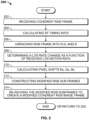
- method 200 for calibrating a synthetic image on an avionic display in a cockpit of an aircraft is described, in accordance with exemplary embodiments of the present disclosure.
- the following description of method 200 may refer to elements mentioned above in connection with FIG 1 .
- portions of method 200 may be performed by different components of the described system.
- method 200 may include any number of additional or alternative tasks, the tasks shown in FIG. 2 need not be performed in the illustrated order, and method 200 may be incorporated into a more comprehensive procedure or method having additional functionality not described in detail herein.
- one or more of the tasks shown in FIG. 2 could be omitted from an embodiment of the method 200 as long as the intended overall functionality remains intact.
- system 102 Prior to operation, the system 102 is understood to be configured and operational for position-determining operations, movement-determining operations, and generating a vehicle or avionic display for a user to view on the CS display 20 of the display system 112 .
- the system 102 receives an initial coherent RGB frame 115 from the source of frame 108 .
- the system 102 calculates the SF timing rate based on the frequency of the CS display 20 , as described above.
- the system 102 begins an unpacking operation, in which it unpacks the initial coherent RGB image frame 115 into a separate Red frame, Green frame, and Blue frame.
- a LOS monitoring module may receive one or more motion rates and generates therefrom a LOS rate of change.
- the system 102 computes a Red pixel shift, a Green pixel shift, and a Blue pixel shift (Rs, Gs, Bs), that reflects the LOS rate of change.
- a modified sub-frame for each of the R,G,B frames is constructed by applying the red pixel shift (Rs) to the red frame, the green pixel shift (Gs) to the green frame, and the blue pixel shift (Bs) to the blue frame; the resulting modified sub-frames are collectively referred to as modified RGB sub-frames.
- the system 102 re-packs the modified RGB sub-frames into a modified coherent RGB image frame 117 for rendering on the CS display 20 .
- the method may end, or return to 202 .
- the present disclosure has provided several embodiments of systems and methods for providing image motion artifact correction for a color sequential (CS) display in a display system in a vehicle.
- the disclosed pixel shift module 104 operates on an initial coherent RGB image frame for a CS display, converting the initial coherent RGB image frame 115 into a modified coherent RGB image frame 117, in which the respective RGB sub-frames, when displayed by the CS display, are coherent and aligned- on the eye retina- even in the presence of the temporal shifting of the RGB sub-frames introduced via the sequential nature of the CS display 20. Therefore, in addition to the technical solution provided, the present disclosure provides an objectively improved HMI over available vehicle display systems.
Landscapes
- Engineering & Computer Science (AREA)
- Theoretical Computer Science (AREA)
- Physics & Mathematics (AREA)
- General Physics & Mathematics (AREA)
- Computer Hardware Design (AREA)
- Transportation (AREA)
- Mechanical Engineering (AREA)
- Chemical & Material Sciences (AREA)
- Combustion & Propulsion (AREA)
- General Engineering & Computer Science (AREA)
- Human Computer Interaction (AREA)
- Optics & Photonics (AREA)
- Controls And Circuits For Display Device (AREA)
- Closed-Circuit Television Systems (AREA)
Applications Claiming Priority (1)
| Application Number | Priority Date | Filing Date | Title |
|---|---|---|---|
| US17/466,677 US11790860B2 (en) | 2021-09-03 | 2021-09-03 | Systems and methods for providing image motion artifact correction for a color sequential (CS) display |
Publications (1)
| Publication Number | Publication Date |
|---|---|
| EP4145437A1 true EP4145437A1 (en) | 2023-03-08 |
Family
ID=82939955
Family Applications (1)
| Application Number | Title | Priority Date | Filing Date |
|---|---|---|---|
| EP22190480.8A Pending EP4145437A1 (en) | 2021-09-03 | 2022-08-16 | Systems and methods for providing image motion artifact correction for a color sequential (cs) display |
Country Status (4)
| Country | Link |
|---|---|
| US (1) | US11790860B2 (he) |
| EP (1) | EP4145437A1 (he) |
| CN (1) | CN115767057A (he) |
| IL (1) | IL295198B2 (he) |
Families Citing this family (2)
| Publication number | Priority date | Publication date | Assignee | Title |
|---|---|---|---|---|
| US11851215B2 (en) * | 2021-05-27 | 2023-12-26 | Honeywell International Inc. | Systems and methods for calibrating a synthetic image on an avionic display |
| CN117975852A (zh) * | 2024-01-31 | 2024-05-03 | 昀光微电子(上海)有限公司 | 显示方法、显示装置、电子设备、存储介质及程序产品 |
Citations (3)
| Publication number | Priority date | Publication date | Assignee | Title |
|---|---|---|---|---|
| WO1997020244A1 (en) * | 1995-11-27 | 1997-06-05 | Cae Electronics Ltd. | Method and apparatus for displaying a virtual environment on a video display |
| US8970495B1 (en) * | 2012-03-09 | 2015-03-03 | Google Inc. | Image stabilization for color-sequential displays |
| US20160131912A1 (en) * | 2014-01-21 | 2016-05-12 | Osterhout Group, Inc. | See-through computer display systems |
Family Cites Families (5)
| Publication number | Priority date | Publication date | Assignee | Title |
|---|---|---|---|---|
| US5684498A (en) | 1995-06-26 | 1997-11-04 | Cae Electronics Ltd. | Field sequential color head mounted display with suppressed color break-up |
| US6831948B1 (en) | 1999-07-30 | 2004-12-14 | Koninklijke Philips Electronics N.V. | System and method for motion compensation of image planes in color sequential displays |
| JP2009503617A (ja) | 2005-08-02 | 2009-01-29 | ユニ−ピクセル・ディスプレイズ・インコーポレーテッド | フィールドシーケンシャルカラーディスプレイシステムのカラー分裂アーチファクトを緩和するメカニズム |
| US8179401B2 (en) | 2009-05-21 | 2012-05-15 | Spatial Photonics, Inc. | Reducing image artifacts in a color sequential display system |
| US9626802B2 (en) * | 2014-05-01 | 2017-04-18 | Microsoft Technology Licensing, Llc | Determining coordinate frames in a dynamic environment |
-
2021
- 2021-09-03 US US17/466,677 patent/US11790860B2/en active Active
-
2022
- 2022-07-30 IL IL295198A patent/IL295198B2/he unknown
- 2022-08-09 CN CN202210948470.5A patent/CN115767057A/zh active Pending
- 2022-08-16 EP EP22190480.8A patent/EP4145437A1/en active Pending
Patent Citations (3)
| Publication number | Priority date | Publication date | Assignee | Title |
|---|---|---|---|---|
| WO1997020244A1 (en) * | 1995-11-27 | 1997-06-05 | Cae Electronics Ltd. | Method and apparatus for displaying a virtual environment on a video display |
| US8970495B1 (en) * | 2012-03-09 | 2015-03-03 | Google Inc. | Image stabilization for color-sequential displays |
| US20160131912A1 (en) * | 2014-01-21 | 2016-05-12 | Osterhout Group, Inc. | See-through computer display systems |
Also Published As
| Publication number | Publication date |
|---|---|
| IL295198A (he) | 2023-04-01 |
| IL295198B2 (he) | 2026-03-01 |
| IL295198B1 (he) | 2025-11-01 |
| CN115767057A (zh) | 2023-03-07 |
| US20230074306A1 (en) | 2023-03-09 |
| US11790860B2 (en) | 2023-10-17 |
Similar Documents
| Publication | Publication Date | Title |
|---|---|---|
| EP3889908A2 (en) | Image projection method, apparatus, device and storage medium | |
| US10540007B2 (en) | Systems and methods for delivering imagery to head-worn display systems | |
| EP3021285B1 (en) | Low latency augmented reality display | |
| US11319086B2 (en) | Method and system for aligning a taxi-assist camera | |
| US8089375B1 (en) | Head-up display/synthetic vision system predicted flight path depiction | |
| EP4145437A1 (en) | Systems and methods for providing image motion artifact correction for a color sequential (cs) display | |
| EP3438614B1 (en) | Aircraft systems and methods for adjusting a displayed sensor image field of view | |
| US12293474B2 (en) | Video pass-through computing system | |
| CN106275467A (zh) | 用于整合平视显示器和下视显示器的系统和方法 | |
| US20200221071A1 (en) | System and method for foveated simulation | |
| JP2022095787A (ja) | 表示方法、装置、端末デバイス、コンピュータ可読記憶媒体、およびコンピュータプログラム | |
| US11435580B1 (en) | High dynamic range head-up display | |
| EP4086102B1 (en) | Navigation method and apparatus, electronic device, readable storage medium and computer program product | |
| US10163185B1 (en) | Systems and methods for user driven avionics graphics | |
| EP3622486B1 (en) | Holographic illustration of weather | |
| US12087170B2 (en) | Methods and systems for displaying simplified primary flight information for an urban air mobility vehicle (UAMV) | |
| US11403058B2 (en) | Augmented reality vision system for vehicular crew resource management | |
| US10657867B1 (en) | Image control system and method for translucent and non-translucent displays | |
| US10917585B2 (en) | Method and system for facilitating transportation of an observer in a vehicle | |
| US20250156990A1 (en) | Information processing device, information processing method, and program | |
| Batchko et al. | Advancements in Flight Simulation Visual Systems: An In-Depth Analysis of Variable Collimation Display Technology | |
| US11961184B2 (en) | System and method for scene reconstruction with plane and surface reconstruction | |
| US10970853B2 (en) | Determining method of a virtual velocity vector of a mobile engine, associated computer program product and determining system | |
| US20160219245A1 (en) | Platform-mounted artificial vision system | |
| CN118037766A (zh) | 图像处理方法和装置 |
Legal Events
| Date | Code | Title | Description |
|---|---|---|---|
| PUAI | Public reference made under article 153(3) epc to a published international application that has entered the european phase |
Free format text: ORIGINAL CODE: 0009012 |
|
| STAA | Information on the status of an ep patent application or granted ep patent |
Free format text: STATUS: THE APPLICATION HAS BEEN PUBLISHED |
|
| AK | Designated contracting states |
Kind code of ref document: A1 Designated state(s): AL AT BE BG CH CY CZ DE DK EE ES FI FR GB GR HR HU IE IS IT LI LT LU LV MC MK MT NL NO PL PT RO RS SE SI SK SM TR |
|
| P01 | Opt-out of the competence of the unified patent court (upc) registered |
Effective date: 20230525 |
|
| STAA | Information on the status of an ep patent application or granted ep patent |
Free format text: STATUS: REQUEST FOR EXAMINATION WAS MADE |
|
| 17P | Request for examination filed |
Effective date: 20230904 |
|
| RBV | Designated contracting states (corrected) |
Designated state(s): AL AT BE BG CH CY CZ DE DK EE ES FI FR GB GR HR HU IE IS IT LI LT LU LV MC MK MT NL NO PL PT RO RS SE SI SK SM TR |
|
| STAA | Information on the status of an ep patent application or granted ep patent |
Free format text: STATUS: EXAMINATION IS IN PROGRESS |
|
| 17Q | First examination report despatched |
Effective date: 20250806 |