EP4145028A1 - Refrigeration cycle device - Google Patents
Refrigeration cycle device Download PDFInfo
- Publication number
- EP4145028A1 EP4145028A1 EP20933555.3A EP20933555A EP4145028A1 EP 4145028 A1 EP4145028 A1 EP 4145028A1 EP 20933555 A EP20933555 A EP 20933555A EP 4145028 A1 EP4145028 A1 EP 4145028A1
- Authority
- EP
- European Patent Office
- Prior art keywords
- aperture
- way valve
- heat exchanger
- valve
- indoor heat
- Prior art date
- Legal status (The legal status is an assumption and is not a legal conclusion. Google has not performed a legal analysis and makes no representation as to the accuracy of the status listed.)
- Withdrawn
Links
Images



Classifications
-
- F—MECHANICAL ENGINEERING; LIGHTING; HEATING; WEAPONS; BLASTING
- F25—REFRIGERATION OR COOLING; COMBINED HEATING AND REFRIGERATION SYSTEMS; HEAT PUMP SYSTEMS; MANUFACTURE OR STORAGE OF ICE; LIQUEFACTION SOLIDIFICATION OF GASES
- F25B—REFRIGERATION MACHINES, PLANTS OR SYSTEMS; COMBINED HEATING AND REFRIGERATION SYSTEMS; HEAT PUMP SYSTEMS
- F25B13/00—Compression machines, plants or systems, with reversible cycle
-
- F—MECHANICAL ENGINEERING; LIGHTING; HEATING; WEAPONS; BLASTING
- F25—REFRIGERATION OR COOLING; COMBINED HEATING AND REFRIGERATION SYSTEMS; HEAT PUMP SYSTEMS; MANUFACTURE OR STORAGE OF ICE; LIQUEFACTION SOLIDIFICATION OF GASES
- F25B—REFRIGERATION MACHINES, PLANTS OR SYSTEMS; COMBINED HEATING AND REFRIGERATION SYSTEMS; HEAT PUMP SYSTEMS
- F25B41/00—Fluid-circulation arrangements
- F25B41/20—Disposition of valves, e.g. of on-off valves or flow control valves
-
- F—MECHANICAL ENGINEERING; LIGHTING; HEATING; WEAPONS; BLASTING
- F25—REFRIGERATION OR COOLING; COMBINED HEATING AND REFRIGERATION SYSTEMS; HEAT PUMP SYSTEMS; MANUFACTURE OR STORAGE OF ICE; LIQUEFACTION SOLIDIFICATION OF GASES
- F25B—REFRIGERATION MACHINES, PLANTS OR SYSTEMS; COMBINED HEATING AND REFRIGERATION SYSTEMS; HEAT PUMP SYSTEMS
- F25B41/00—Fluid-circulation arrangements
- F25B41/20—Disposition of valves, e.g. of on-off valves or flow control valves
- F25B41/26—Disposition of valves, e.g. of on-off valves or flow control valves of fluid flow reversing valves
-
- F—MECHANICAL ENGINEERING; LIGHTING; HEATING; WEAPONS; BLASTING
- F25—REFRIGERATION OR COOLING; COMBINED HEATING AND REFRIGERATION SYSTEMS; HEAT PUMP SYSTEMS; MANUFACTURE OR STORAGE OF ICE; LIQUEFACTION SOLIDIFICATION OF GASES
- F25B—REFRIGERATION MACHINES, PLANTS OR SYSTEMS; COMBINED HEATING AND REFRIGERATION SYSTEMS; HEAT PUMP SYSTEMS
- F25B41/00—Fluid-circulation arrangements
- F25B41/40—Fluid line arrangements
- F25B41/42—Arrangements for diverging or converging flows, e.g. branch lines or junctions
-
- F—MECHANICAL ENGINEERING; LIGHTING; HEATING; WEAPONS; BLASTING
- F25—REFRIGERATION OR COOLING; COMBINED HEATING AND REFRIGERATION SYSTEMS; HEAT PUMP SYSTEMS; MANUFACTURE OR STORAGE OF ICE; LIQUEFACTION SOLIDIFICATION OF GASES
- F25B—REFRIGERATION MACHINES, PLANTS OR SYSTEMS; COMBINED HEATING AND REFRIGERATION SYSTEMS; HEAT PUMP SYSTEMS
- F25B2313/00—Compression machines, plants or systems with reversible cycle not otherwise provided for
- F25B2313/023—Compression machines, plants or systems with reversible cycle not otherwise provided for using multiple indoor units
- F25B2313/0233—Compression machines, plants or systems with reversible cycle not otherwise provided for using multiple indoor units in parallel arrangements
-
- F—MECHANICAL ENGINEERING; LIGHTING; HEATING; WEAPONS; BLASTING
- F25—REFRIGERATION OR COOLING; COMBINED HEATING AND REFRIGERATION SYSTEMS; HEAT PUMP SYSTEMS; MANUFACTURE OR STORAGE OF ICE; LIQUEFACTION SOLIDIFICATION OF GASES
- F25B—REFRIGERATION MACHINES, PLANTS OR SYSTEMS; COMBINED HEATING AND REFRIGERATION SYSTEMS; HEAT PUMP SYSTEMS
- F25B2313/00—Compression machines, plants or systems with reversible cycle not otherwise provided for
- F25B2313/027—Compression machines, plants or systems with reversible cycle not otherwise provided for characterised by the reversing means
- F25B2313/02732—Compression machines, plants or systems with reversible cycle not otherwise provided for characterised by the reversing means using two three-way valves
-
- F—MECHANICAL ENGINEERING; LIGHTING; HEATING; WEAPONS; BLASTING
- F25—REFRIGERATION OR COOLING; COMBINED HEATING AND REFRIGERATION SYSTEMS; HEAT PUMP SYSTEMS; MANUFACTURE OR STORAGE OF ICE; LIQUEFACTION SOLIDIFICATION OF GASES
- F25B—REFRIGERATION MACHINES, PLANTS OR SYSTEMS; COMBINED HEATING AND REFRIGERATION SYSTEMS; HEAT PUMP SYSTEMS
- F25B2400/00—Component parts or details not otherwise provided for in this subclass
- F25B2400/23—Separators
Definitions
- the present disclosure relates to a refrigeration cycle apparatus.
- a refrigeration cycle apparatus including an outdoor unit, a plurality of indoor units, and a branch unit, wherein the outdoor unit and the plurality of indoor units are connected via the branch unit.
- Japanese Patent Laying-Open No. 4-6361 discloses a refrigeration cycle apparatus in which an outdoor unit and a branch unit are connected via a first refrigerant pipe and a second refrigerant pipe.
- the refrigeration cycle apparatus includes: a first refrigerant flow path switching mechanism arranged in the outdoor unit; and a second refrigerant flow path switching mechanism arranged in the branch unit.
- the first flow path switching mechanism includes one four-way valve and four check valves.
- the first refrigerant flow path mechanism switches between a cooling operation state in which the outdoor heat exchanger acts as a condenser and a heating operation state in which the outdoor heat exchanger acts as an evaporator, and a state in which the pressure of the refrigerant flowing through the first refrigerant pipe is lower than the pressure of the refrigerant flowing through the second refrigerant pipe is maintained irrespective of the switching between the cooling operation state and the heating operation state.
- the inner diameter of the first refrigerant pipe is larger than the inner diameter of the second refrigerant pipe.
- the second flow path switching mechanism includes a plurality of flow path switching valves.
- the second refrigerant flow path mechanism switches between a full-cooling operation state or full-heating operation state in which all of the plurality of indoor units each act as an evaporator or condenser and a cooling-dominated operation state or heating-dominated operation in which part of the plurality of indoor units each act as a condenser and the other part of the plurality of indoor units each act as an evaporator.
- a refrigeration cycle apparatus comprises a refrigerant circuit in which refrigerant circulates, the refrigerant circuit comprising a compressor, a flow path switching portion, an outdoor heat exchanger, a decompressing apparatus, a first indoor heat exchanger, a first connecting pipe through which the refrigerant flows into the first indoor heat exchanger, and a second connecting pipe through which the refrigerant flows from the first indoor heat exchanger.
- the flow path switching portion is configured to switch between a cooling operation state in which the outdoor heat exchanger acts as a condenser and a heating operation state in which the outdoor heat exchanger acts as an evaporator.
- the refrigerant circuit further comprises: a first three-way valve arranged downstream of the first indoor heat exchanger in the cooling operation state and arranged upstream of the first indoor heat exchanger in the heating operation state; and a second three-way valve arranged upstream of the first indoor heat exchanger in the cooling operation state and arranged downstream of the first indoor heat exchanger in the heating operation state.
- Each of the first three-way valve and the second three-way valve comprises: a valve seat having a valve chamber and provided with a first aperture, a second aperture and a third aperture, the first aperture, the second aperture, and the third aperture being connected to the valve chamber; and a valve body configured to move among a first position, a second position, and a third position in the valve chamber.
- the first aperture of each of the first three-way valve and the second three-way valve is connected to one end or the other end of the first indoor heat exchanger in the refrigerant circuit.
- the second aperture of each of the first three-way valve and the second three-way valve is connected to the first connecting pipe.
- the third aperture of each of the first three-way valve and the second three-way valve is connected to the second connecting pipe.
- Each of the first three-way valve and the second three-way valve is configured to be switched independently to one of a first state in which the valve body is located at the first position, a second state in which the valve body is located at the second position, and a third state in which the valve body is located at the third position.
- a first space is arranged in the valve chamber, the first space communicating with the first aperture and the second aperture and being separated from the third aperture
- a second space is arranged in the valve chamber, the second space communicating with the first aperture, the second aperture, and the third aperture
- a third space is arranged in the valve chamber, the third space communicating with the first aperture and the third aperture and being separated from the second aperture.
- a refrigeration cycle apparatus can be provided to suppress occurrence of chattering while preventing decreased comfortability when load of an indoor heat exchanger is decreased.
- a refrigeration cycle apparatus 1000 includes a refrigerant circuit in which refrigerant circulates.
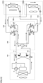
- the refrigerant circuit includes a compressor 1, a four-way valve 2 serving as a flow path switching portion, an outdoor heat exchanger 3, a first decompressing apparatus 4A, a second decompressing apparatus 4B, a first indoor heat exchanger 5A, a second indoor heat exchanger 5B, a first check valve 6A, a second check valve 6B, a third check valve 6C, a fourth check valve 6D, a gas-liquid separator 7, a first three-way valve 8A, a second three-way valve 9A, a third three-way valve 8B, a fourth three-way valve 9B, a first connecting pipe 10, a second connecting pipe 11, a third connecting pipe 12A, a fourth connecting pipe 13A, a fifth connecting pipe 12B, and a sixth connecting pipe 13B.
- Compressor 1 four-way valve 2, outdoor heat exchanger 3, first check valve 6A, second check valve 6B, third check valve 6C, and fourth check valve 6D are accommodated in an outdoor unit 100.
- First decompressing apparatus 4A and first indoor heat exchanger 5A are accommodated in a first indoor unit 200A.
- Second decompressing apparatus 4B and second indoor heat exchanger 5B are accommodated in a second indoor unit 200B.
- Gas-liquid separator 7, first three-way valve 8A, second three-way valve 9A, third three-way valve 8B, and fourth three-way valve 9B are accommodated in a branch unit 300.
- First connecting pipe 10 and second connecting pipe 11 are arranged between outdoor unit 100 and branch unit 300 so as to connect outdoor unit 100 and branch unit 300 to each other.
- Third connecting pipe 12A and fourth connecting pipe 13A are arranged between first indoor unit 200A and branch unit 300 so as to connect first indoor unit 200A and branch unit 300 to each other.
- Fifth connecting pipe 12B and sixth connecting pipe 13B are arranged between second indoor unit 200B and branch unit 300 so as to connect second indoor unit 200B and branch unit 300 to each other.
- Compressor 1 has a discharge port through which the refrigerant is discharged and a suction port through which the refrigerant is suctioned.
- Compressor 1 is, for example, a constant-speed compressor having a constant driving frequency. It should be noted that compressor 1 may be, for example, an inverter compressor having a driving frequency controlled by an inverter.
- Four-way valve 2 has first to fourth ports.
- the first port is connected to the discharge port of compressor 1.
- the second port is connected to the suction port of compressor 1.
- the third port is connected to first connecting pipe 10 via outdoor heat exchanger 3 and first check valve 6A, and is connected to second connecting pipe 11 via outdoor heat exchanger 3 and second check valve 6B.
- the fourth port is connected to first connecting pipe 10 via third check valve 6C, and is connected to second connecting pipe 11 via fourth check valve 6D.
- Four-way valve 2 switches between a cooling operation state in which the first port communicates with the third port and the second port communicates with the fourth port and a heating operation state in which the first port communicates with the fourth port and the second port communicates with the third port.
- First decompressing apparatus 4A and second decompressing apparatus 4B are, for example, expansion valves. In each of first decompressing apparatus 4A and second decompressing apparatus 4B, the refrigerant is expanded. In each of first indoor heat exchanger 5A and second indoor heat exchanger 5B, heat is exchanged between the refrigerant circulating in the refrigerant circuit and indoor air.
- First indoor unit 200A and second indoor unit 200B are installed, for example, in different rooms.
- Outdoor unit 100 is provided with: a refrigerant flow path that connects between outdoor heat exchanger 3 and first connecting pipe 10; a refrigerant flow path that connects between outdoor heat exchanger 3 and second connecting pipe 11; a refrigerant flow path that connects between the fourth port of four-way valve 2 and first connecting pipe 10; and a refrigerant flow path that connects between the fourth port of four-way valve 2 and second connecting pipe 11.
- First check valve 6A is arranged in the refrigerant flow path between outdoor heat exchanger 3 and first connecting pipe 10, and permits only the flow of the refrigerant from outdoor heat exchanger 3 to first connecting pipe 10. First check valve 6A blocks the flow of the refrigerant from first connecting pipe 10 to outdoor heat exchanger 3.
- Second check valve 6B is arranged in the refrigerant flow path between outdoor heat exchanger 3 and second connecting pipe 11, and permits only the flow of the refrigerant from second connecting pipe 11 to the outdoor heat exchanger. Second check valve 6B blocks the flow of the refrigerant from second connecting pipe 11 to outdoor heat exchanger 3.
- Third check valve 6C is arranged in the refrigerant flow path between the fourth port of four-way valve 2 and first connecting pipe 10, and permits only the flow of the refrigerant from the fourth port of four-way valve 2 to the second connecting pipe. Third check valve 6C blocks the flow of the refrigerant from first connecting pipe 10 to the fourth port of four-way valve 2.
- Fourth check valve 6D is arranged in the refrigerant flow path between the fourth port of four-way valve 2 and second connecting pipe 11, and permits only the flow of the refrigerant from second connecting pipe 11 to the fourth port of four-way valve 2. Fourth check valve 6D blocks the flow of the refrigerant from the fourth port of four-way valve 2 to second connecting pipe 11.
- Gas-liquid separator 7 is connected to first connecting pipe 10 and has an flow inlet 71 via which the refrigerant flows in, a first flow outlet 72 via which the gas-phase refrigerant flows out, and a second flow outlet 73 via which the liquid-phase refrigerant flows out.
- First three-way valve 8A, second three-way valve 9A, third three-way valve 8B, and fourth three-way valve 9B have the same configuration. As shown in Figs. 2 to 7 , each of first three-way valve 8A, second three-way valve 9A, third three-way valve 8B, and fourth three-way valve 9B includes a valve seat 14 and a valve body 15.
- Each of valve seats 14 of first three-way valve 8A, second three-way valve 9A, third three-way valve 8B, and fourth three-way valve 9B includes a valve chamber 16 and is provided with a first aperture P1, a second aperture P2, and a third aperture P3, first aperture P1, second aperture P2, and third aperture P3 communicating with valve chamber 16.
- Valve seat 14 has a first surface 14A facing valve chamber 16 and provided with one end of each of first aperture P1 and third aperture P3, and a second surface 14B provided with one end of second aperture P2.
- First aperture P1 is arranged beside third apertures P3 with an interval being interposed therebetween in a peripheral direction serving as a first direction.
- the aperture area of third aperture P3 is equal to, for example, the aperture area of first aperture P1.
- Second surface 14B faces first surface 14A with valve body 15 being interposed therebetween in a Z direction serving as a second direction, for example.
- Second aperture P2 is arranged to overlap with the rotation axis of valve body 15 when viewed in the Z direction, for example.
- the shortest distance between the respective centers of second aperture P2 and first aperture P1 is equal to, for example, the shortest distance between the respective centers of second aperture P2 and third aperture P3.
- First aperture P1 of first three-way valve 8A is connected to first indoor heat exchanger 5A via third connecting pipe 12A.
- Second aperture P2 of first three-way valve 8A is connected to first flow outlet 72 of gas-liquid separator 7. That is, second aperture P2 of first three-way valve 8A is connected to first connecting pipe 10 via gas-liquid separator 7.
- Third aperture P3 of first three-way valve 8A is connected to second connecting pipe 11.
- First aperture P1 of second three-way valve 9A is connected to first indoor heat exchanger 5A via fourth connecting pipe 13A.
- Second aperture P2 of second three-way valve 9A is connected to second flow outlet 73 of gas-liquid separator 7. That is, second aperture P2 of second three-way valve 9A is connected to first connecting pipe 10 via gas-liquid separator 7.
- Third aperture P3 of second three-way valve 9A is connected to second connecting pipe 11.
- First aperture P1 of third three-way valve 8B is connected to second indoor heat exchanger 5B via fifth connecting pipe 12B.
- Second aperture P2 of third three-way valve 8B is connected to first flow outlet 72 of gas-liquid separator 7. That is, second aperture P2 of third three-way valve 8B is connected to first connecting pipe 10 via gas-liquid separator 7.
- Third aperture P3 of third three-way valve 8B is connected to second connecting pipe 11.
- First aperture P1 of fourth three-way valve 9B is connected to second indoor heat exchanger 5B via sixth connecting pipe 13B.
- Second aperture P2 of fourth three-way valve 9B is connected to second flow outlet 73 of gas-liquid separator 7. That is, second aperture P2 of fourth three-way valve 9B is connected to first connecting pipe 10 via gas-liquid separator 7.
- Third aperture P3 of fourth three-way valve 9B is connected to second connecting pipe 11.
- Second aperture P2 of first three-way valve 8A and second aperture P2 of third three-way valve 8B are connected to first flow outlet 72 of gas-liquid separator 7 and first connecting pipe 10 in parallel with each other.
- Third aperture P3 of first three-way valve 8A and third aperture P3 of third three-way valve 8B are connected to second connecting pipe 11 in parallel with each other.
- Second aperture P2 of second three-way valve 9A and second aperture P2 of fourth three-way valve 9B are connected to second flow outlet 73 of gas-liquid separator 7 and first connecting pipe 10 in parallel with each other.
- Third aperture P3 of second three-way valve 9A and third aperture P3 of fourth three-way valve 9B are connected to second connecting pipe 11 in parallel with each other.
- valve bodies 15 of first three-way valve 8A, second three-way valve 9A, third three-way valve 8B, and fourth three-way valve 9B moves among a first position, a second position, and a third position in valve chamber 16.
- Valve body 15 is provided to rotate about, for example, a rotation axis extending along the Z direction. Valve body 15 rotates, for example, in a peripheral direction from third aperture P3 toward first aperture P1 and in a direction opposite thereto.
- Valve body 15 is connected to a rotation shaft of a motor (not shown) via, for example, a gear 17.
- Valve body 15 has a third surface 18 slidable on first surface 14A, and is provided with a recess 19 arranged beside third surface 18 in the peripheral direction serving as the first direction and recessed with respect to third surface 18, and has a fourth surface 20 located opposite to third surface 18 and facing second surface 14B of valve seat 14 with an interval being interposed therebetween in the Z direction.
- Valve body 15 has: a first end portion 151 in the peripheral direction; and a second end portion 152 located opposite to first end portion 151 in the peripheral direction.
- First end portion 151 is an end portion arranged on the front side with respect to second end portion 152 when valve body 15 rotates in the peripheral direction from third aperture P3 toward first aperture P1.
- Second end portion 152 is an end portion arranged on the front side with respect to first end portion 151 when valve body 15 rotates in the peripheral direction from first aperture P1 toward third aperture P3.
- Recess 19 has: a third end portion 191 in the peripheral direction; and a fourth end portion 192 located opposite to third end portion 191 in the peripheral direction.
- Third end portion 191 is an end portion arranged on the rear side with respect to first end portion 151 and on the front side with respect to fourth end portion 192 when valve body 15 rotates in the peripheral direction from third aperture P3 toward first aperture P1.
- Fourth end portion 192 is an end portion arranged on the rear side with respect to second end portion 152 and on the front side with respect to third end portion 191 when valve body 15 rotates in the peripheral direction from first aperture P1 toward third aperture P3.
- An interval between first end portion 151 and third end portion 191 in the peripheral direction is wider than an interval between second end portion 152 and fourth end portion 192 in the peripheral direction.
- Third surface 18 is arranged at least between first end portion 151 and third end portion 191 and around the entire periphery of recess 19 in the peripheral direction.
- valve body 15 when valve body 15 is located at the second position, valve body 15 is provided not to overlap with at least a portion of each of first aperture P1 and third aperture P3 when viewed from the second aperture P2 side. As indicated by a dotted line in Fig. 4 , when valve body 15 is located at the second position, valve body 15 is provided not to overlap with, for example, first aperture P1 and third aperture P3 when viewed from the second aperture P2 side. Valve body 15 is provided to allow second space S2 to be continuous to a whole of each of first aperture P1 and third aperture P3.
- an angle ⁇ 1 formed with respect to the rotation axis by first end portion 151 and second end portion 152 of valve body 15 outside valve body 15 is equal to, for example, an angle ⁇ 2 formed with respect to the rotation axis by a first imaginary line L1 passing through the rotation axis of valve body 15 and tangent to first aperture P1 and a second imaginary line L2 passing through the rotation axis of valve body 15 and tangent to third aperture P3.
- recess 19 when viewed from the second aperture P2 side, recess 19 is provided to overlap with a whole of each of first aperture P1 and third aperture P3 when valve body 15 is located at the third position.
- An angle ⁇ 3 formed with respect to the rotation axis by third end portion 191 and fourth end portion 192 of recess 19 is equal to, for example, angle ⁇ 2 described above.
- Each of first three-way valve 8A, second three-way valve 9A, third three-way valve 8B, and fourth three-way valve 9B can be in the following three states: a first state in which valve body 15 is located at the first position; a second state in which valve body 15 is located at the second position; and a third state in which valve body 15 is located at the third position.
- Each of first three-way valve 8A, second three-way valve 9A, third three-way valve 8B, and fourth three-way valve 9B is switchable independently to one of the above-described three states.
- valve body 15 in the first state, a first space S1 communicating with first aperture P1 and second aperture P2 and separated from third aperture P3 by valve body 15 is arranged in each valve chamber 16.
- valve body 15 does not overlap with first aperture P1 in the Z direction.
- Third surface 18 of valve body 15 overlaps with a whole of third aperture P3, and closes third aperture P3.
- Recess 19 of valve body 15 does not overlap with first aperture P1 and third aperture P3.
- Third surface 18 is arranged to overlap with a whole of third aperture P3 when viewed from the second aperture P2 side.
- First end portion 151 and third end portion 191 of valve body 15 are arranged to sandwich third aperture P3 therebetween in the peripheral direction when viewed from the second aperture P2 side.
- Recess 19 is arranged not to overlap with first aperture P1 and third aperture P3 when viewed from the second aperture P2 side.
- second space S2 communicating with first aperture P1, second aperture P2, and third aperture P3 is arranged in valve chamber 16.
- the second space forms a branched flow path or a merged flow path.
- valve body 15 does not overlap with first aperture P1 in the Z direction.
- Valve body 15 does not overlap with at least a portion of third aperture P3 in the Z direction.
- Valve body 15 is arranged, for example, at a second position indicated by a solid line in Fig. 4 .
- third surface 18 is arranged to overlap with only a portion of third aperture P3 when viewed from the second aperture P2 side.
- the aperture area of the region of third aperture P3 which does not overlap with valve body 15 is smaller than the aperture area of first aperture P1, for example.
- Valve body 15 may be arranged, for example, at the second position indicated by a dotted line in Fig. 4 .
- third surface 18 is arranged not to overlap with third aperture P3 when viewed from the second aperture P2 side.
- a third space S3 communicating with first aperture P1 and third aperture P3 and separated from second aperture P2 is arranged in recess 19 of valve body 15.
- recess 19 of valve body 15 is arranged to overlap with first aperture P1 and third aperture P3 in the Z direction.
- Refrigeration cycle apparatus 1000 is switched by four-way valve 2 between a cooling operation state in which outdoor heat exchanger 3 acts as a condenser and a heating operation state in which outdoor heat exchanger 3 acts as an evaporator. Further, refrigeration cycle apparatus 1000 is switched by first three-way valve 8A, second three-way valve 9A, third three-way valve 8B, and fourth three-way valve 9B to a full-cooling operation state, a cooling-dominated operation state, a full-heating operation state, or a heating-dominated operation.
- refrigeration cycle apparatus 1000 In the full-cooling operation state, refrigeration cycle apparatus 1000 is switched among a first full-cooling operation state shown in Fig. 8 , a second full-cooling operation state shown in Fig. 9 , and a third full-cooling operation state not shown. Similarly, in the full-heating operation state, refrigeration cycle apparatus 1000 is switched among a first full-heating operation state shown in Fig. 10 , a second full-heating operation state shown in Fig. 11 , and a third full-heating operation state not shown.
- the first full-cooling operation state shown in Fig. 8 is realized when each of loads of first indoor heat exchanger 5A and second indoor heat exchanger 5B is comparatively high.
- each of first three-way valve 8A and third three-way valve 8B is in the third state
- each of second three-way valve 9A and fourth three-way valve 9B is in the first state.
- the refrigerant flows in the refrigerant circuit along arrows in Fig. 8 .
- High-pressure gas-phase refrigerant discharged from compressor 1 is condensed in outdoor heat exchanger 3 into high-pressure liquid-phase refrigerant or gas-liquid two-phase refrigerant, and flows out to first connecting pipe 10.
- the high-pressure liquid-phase refrigerant or gas-liquid two-phase refrigerant having flowed through first connecting pipe 10 flows into gas-liquid separator 7 via flow inlet 71.
- the high-pressure liquid-phase refrigerant having flowed out from second flow outlet 73 is branched in branch unit 300, reaches each of second apertures P2 of second three-way valve 9A and fourth three-way valve 9B that are in the first state, flows through each of the first spaces, and flows out from each of first apertures P1 to fourth connecting pipe 13A or sixth connecting pipe 13B.
- the liquid-phase refrigerant having flowed through fourth connecting pipe 13A is decompressed by first decompressing apparatus 4A, is then evaporated in first indoor heat exchanger 5A, and flows out to third connecting pipe 12A as low-pressure gas-phase refrigerant.
- the liquid-phase refrigerant having flowed through sixth connecting pipe 13B is decompressed by second decompressing apparatus 4B, is then evaporated in second indoor heat exchanger 5B, and flows out to fifth connecting pipe 12B as low-pressure gas-phase refrigerant.
- the low-pressure gas-phase refrigerant having flowed through third connecting pipe 12A or fifth connecting pipe 12B reaches first apertures P1 of first three-way valve 8A and third three-way valve 8B that are in the third state, flows through each of the third spaces, and then flows out from third apertures P3.
- the flows of the gas-phase refrigerant from third apertures P3 are merged in branch unit 300 and the gas-phase refrigerant flows out to second connecting pipe 11.
- the second full-cooling operation state shown in Fig. 9 is realized when only the load of first indoor heat exchanger 5A becomes lower than a predetermined value, for example. It should be noted that the load of second indoor heat exchanger 5B in the second full-cooling operation state may be decreased to be lower than the load of second indoor heat exchanger 5B in the first full-cooling operation state.
- each of first three-way valve 8A and third three-way valve 8B is in the third state
- fourth three-way valve 9B is in the first state
- second three-way valve 9A is in the second state. That is, the second full-cooling operation state shown in Fig. 9 is different from the first full-cooling operation state shown in Fig. 8 only in that second three-way valve 9A is in the second state.
- the refrigerant flows in the refrigerant circuit along arrows in Fig. 9 .
- the high-pressure liquid-phase refrigerant having flowed out from second flow outlet 73 is branched in branch unit 300, and part of the high-pressure liquid-phase refrigerant reaches second aperture P2 of second three-way valve 9A that is in the second state.
- the high-pressure liquid-phase refrigerant having flowed into second aperture P2 of second three-way valve 9A flows through the second space and is accordingly further branched in valve chamber 16.
- the part of the high-pressure liquid-phase refrigerant having flowed into second aperture P2 of second three-way valve 9A flows out from third aperture P3.
- the liquid-phase refrigerant having flowed out from third aperture P3 of second three-way valve 9A is merged with the low-pressure gas-phase refrigerant having flowed out from each of third apertures P3 of first three-way valve 8A and third three-way valve 8B in branch unit 300, and flows out to second connecting pipe 11.
- the remainder of the high-pressure liquid-phase refrigerant having flowed into second aperture P2 flows out from first aperture P1 to fourth connecting pipe 13A, is decompressed by first decompressing apparatus 4A, and is then evaporated in first indoor heat exchanger 5A.
- an amount of refrigerant flowing through first indoor heat exchanger 5A is controlled as a ratio of the aperture areas of first aperture P1 and third aperture P3 when viewed from the second aperture P2 side of second three-way valve 9A.
- the ratio is controlled as a rotation angle of valve body 15 of second three-way valve 9A.
- the switching between the first full-cooling operation state shown in Fig. 8 and the second full-cooling operation state shown in Fig. 9 and the control of the rotation angle of valve body 15 of second three-way valve 9A in the second full-cooling operation state shown in Fig. 9 are performed to bring the evaporation temperature in first indoor heat exchanger 5A into a target evaporation temperature, for example.
- valve body 15 of second three-way valve 9A rotates from the first position to the second position.
- the evaporation temperature is always or regularly measured by a temperature sensor (not shown) attached to first indoor heat exchanger 5A, for example.
- the determination of the evaporation temperature and the control of the rotation angle of valve body 15 are always or regularly performed by control unit 310, for example.
- the driving frequency of compressor 1 is constant, for example.
- the expression "the driving frequency is constant” means that the maximum value and minimum value of the driving frequency fall within a range of 95% or more and 105% or less of the average value thereof.
- the switching between the first full-cooling operation state shown in Fig. 8 and the second full-cooling operation state shown in Fig. 9 and the control of the rotation angle of valve body 15 of second three-way valve 9A in the second full-cooling operation state shown in Fig. 9 may be performed when a difference between the evaporation temperature of first indoor heat exchanger 5A and the target evaporation temperature falls out of a predetermined range.
- the third full-cooling operation state is realized, for example, when only the load of second indoor heat exchanger 5B becomes lower than a predetermined value.
- each of first three-way valve 8A and third three-way valve 8B is in the third state
- second three-way valve 9A is in the first state
- fourth three-way valve 9B is in the second state.
- the flow rate of the refrigerant flowing in second indoor heat exchanger 5B in the third full-cooling operation state becomes lower than the flow rate of the refrigerant flowing in second indoor heat exchanger 5B in the first full-cooling operation state shown in Fig. 8 .
- the first full-heating operation state shown in Fig. 10 is realized when each of loads of first indoor heat exchanger 5A and second indoor heat exchanger 5B is comparatively high.
- each of first three-way valve 8A and third three-way valve 8B is in the first state
- each of second three-way valve 9A and fourth three-way valve 9B is in the third state.
- the refrigerant flows in the refrigerant circuit along arrows in Fig. 10 .
- High-pressure gas-phase refrigerant discharged from compressor 1 flows out to first connecting pipe 10 through third check valve 6C.
- the high-pressure gas-phase refrigerant having flowed through first connecting pipe 10 flows into gas-liquid separator 7 via flow inlet 71.
- the high-pressure gas-phase refrigerant having flowed out from first flow outlet 72 is branched in branch unit 300, reaches each of second apertures P2 of first three-way valve 8A and third three-way valve 8B that are in the first state, flows through each of the first spaces, and flows out from each of first apertures P1 to third connecting pipe 12A or fifth connecting pipe 12B.
- the gas-phase refrigerant having flowed through third connecting pipe 12A is condensed in first indoor heat exchanger 5A, is then decompressed by first decompressing apparatus 4A, and flows out to fourth connecting pipe 13A as low-pressure gas-liquid two-phase refrigerant.
- the gas-phase refrigerant having flowed through fifth connecting pipe 12B is condensed in second indoor heat exchanger 5B, is then decompressed by second decompressing apparatus 4B, and flows out to sixth connecting pipe 13B as low-pressure gas-liquid two-phase refrigerant.
- the flows of the gas-phase refrigerant from third apertures P3 are merged in branch unit 300 and the gas-phase refrigerant flows out to second connecting pipe 11.
- the second full-heating operation state shown in Fig. 11 is realized, for example, when only the load of first indoor heat exchanger 5A becomes lower than a predetermined value. It should be noted that the load of second indoor heat exchanger 5B in the second full-heating operation state shown in Fig. 11 may be decreased to be lower than that in the first full-heating operation state.
- each of second three-way valve 9A and fourth three-way valve 9B is in the third state, third three-way valve 8B is in the first state, and first three-way valve 8A is in the second state. That is, the second full-heating operation state shown in Fig. 11 is different from the first full-heating operation state shown in Fig. 10 only in that first three-way valve 8A is in the second state.
- the refrigerant flows in the refrigerant circuit along arrows in Fig. 11 .
- High-pressure gas-phase refrigerant having flowed out from first flow outlet 72 is branched in branch unit 300, and part of the high-pressure gas-phase refrigerant reaches second aperture P2 of first three-way valve 8A that is in the second state.
- the high-pressure gas-phase refrigerant having flowed into second aperture P2 of first three-way valve 8A flows through the second space and is accordingly further branched in valve chamber 16.
- Part of the high-pressure gas-phase refrigerant having flowed into second aperture P2 of first three-way valve 8A flows out from third aperture P3.
- the gas-phase refrigerant having flowed out from third aperture P3 of first three-way valve 8A is merged with the low-pressure gas-phase refrigerant having flowed out from each of third apertures P3 of second three-way valve 9A and fourth three-way valve 9B in branch unit 300, and flows out to second connecting pipe 11.
- the remainder of the high-pressure gas-phase refrigerant having flowed into second aperture P2 flows out from first aperture P1 to third connecting pipe 12A, and is condensed in first indoor heat exchanger 5A.
- an amount of refrigerant flowing through first indoor heat exchanger 5A is controlled by first three-way valve 8A.
- the amount of refrigerant flowing through first indoor heat exchanger 5A becomes smaller as the ratio of the aperture area of third aperture P3 to the aperture area of first aperture P1 of first three-way valve 8A is higher.
- the ratio is controlled as a rotation angle of valve body 15 of first three-way valve 8A.
- the switching between the first full-heating operation state shown in Fig. 10 and the second full-heating operation state shown in Fig. 11 , and the control of the rotation angle of valve body 15 of first three-way valve 8A in the second full-heating operation state shown in Fig. 11 are performed to bring the condensation temperature in first indoor heat exchanger 5A into a target condensation temperature, for example.
- a target condensation temperature for example.
- valve body 15 of first three-way valve 8A rotates from the first position to the second position.
- the condensation temperature is always or regularly measured by a temperature sensor (not shown) attached to first indoor heat exchanger 5A, for example.
- control unit 310 determines whether the condensation temperature and the control of the rotation angle of valve body 15 are always or regularly performed by control unit 310, for example.
- the driving frequency of compressor 1 is constant, for example.
- the switching between the first full-heating operation state shown in Fig. 10 and the second full-heating operation state shown in Fig. 11 and the control of the rotation angle of valve body 15 of first three-way valve 8A in the second full-heating operation state shown in Fig. 11 may be performed when a difference between the condensation temperature of first indoor heat exchanger 5A and the target condensation temperature falls out of a predetermined range.
- the third full-heating operation state is realized, for example, when only the load of second indoor heat exchanger 5B becomes lower than a predetermined value.
- each of second three-way valve 9A and fourth three-way valve 9B is in the third state
- first three-way valve 8A is in the first state
- third three-way valve 8B is in the second state.
- the flow rate of the refrigerant flowing in second indoor heat exchanger 5B in the third full-heating operation state becomes lower than the flow rate of the refrigerant flowing in second indoor heat exchanger 5B in the first full-heating operation state shown in Fig. 10 .
- the flow rate of the refrigerant flowing in the indoor heat exchanger in which the load is decreased can be decreased without decreasing the driving frequency of compressor 1, thereby suppressing occurrence of chattering in first check valve 6A, second check valve 6B, third check valve 6C, and fourth check valve 6D while preventing decreased comfortability in the rooms in which the indoor units are arranged.
- the switching among the full-cooling operation state, the cooling-dominated operation state, the full-heating operation state, and the heating-dominated operation state can be realized also when each of first three-way valve 8A, second three-way valve 9A, third three-way valve 8B, and fourth three-way valve 9B is replaced with two or more electromagnetic valves (for example, eight electromagnetic valves).
- the control unit needs to control movement of each of the valve bodies of the eight electromagnetic valves for the purpose of the switching.
- the switching can be performed by controlling, by control unit 310, only the movement of each of the valve bodies of the four three-way valves. Therefore, the number of ports of control unit 310 of refrigeration cycle apparatus 1000 is reduced as compared with that in the refrigeration cycle apparatus including the plurality of electromagnetic valves instead of the three-way valves.
- valve body 15 may be arranged not to overlap with first aperture P1 and third aperture P3 when viewed from the second aperture P2 side.
- the flow rate of the refrigerant flowing through first indoor heat exchanger 5A is further reduced as compared with the case where valve body 15 is arranged to overlap with part of third aperture P3 when viewed from the second aperture P2 side in the second state as indicated by a solid line in Fig. 4 .
- Refrigeration cycle apparatus 1000 is switched between a first cooling-dominated operation state shown in Fig. 12 and a second cooling-dominated operation state (not shown) in the cooling-dominated operation state. Similarly, refrigeration cycle apparatus 1000 is switched between a first heating-dominated operation state shown in Fig. 13 and a second heating-dominated operation state (not shown) in the heating-dominated operation.
- the first cooling-dominated operation state shown in Fig. 12 is realized when the load of first indoor heat exchanger 5A acting as an evaporator is higher than the load of second indoor heat exchanger 5B acting as a condenser.
- each of first three-way valve 8A and fourth three-way valve 9B is in the third state
- third three-way valve 8B is in the first state
- second three-way valve 9A is in the second state.
- the second cooling-dominated operation state is realized when the load of second indoor heat exchanger 5B acting as an evaporator is higher than the load of first indoor heat exchanger 5A acting as a condenser.
- each of second three-way valve 9A and third three-way valve 8B is in the third state
- first three-way valve 8A is in the first state
- fourth three-way valve 9B is in the second state.
- the first heating-dominated operation state shown in Fig. 13 is realized when the load of first indoor heat exchanger 5A acting as a condenser is higher than the load of second indoor heat exchanger 5B acting as an evaporator.
- third three-way valve 8B is in the third state
- first three-way valve 8A and fourth three-way valve 9B are in the first state
- second three-way valve 9A is in the second state.
- the second heating-dominated operation state is realized when the load of second indoor heat exchanger 5B acting as a condenser is higher than the load of first indoor heat exchanger 5A acting as an evaporator.
- first three-way valve 8A is in the third state
- each of second three-way valve 9A and third three-way valve 8B is in the first state
- fourth three-way valve 9B is in the second state.
- Refrigeration cycle apparatus 1000 may include three or more indoor heat exchangers and three-way valves twice as large as the number of the indoor heat exchangers.
- refrigeration cycle apparatus 1000 may further include: a third indoor heat exchanger connected in parallel with first indoor heat exchanger 5A and second indoor heat exchanger 5B; a fifth three-way valve arranged downstream of the third indoor heat exchanger in the cooling operation state and arranged upstream of the third indoor heat exchanger in the heating operation state; and a sixth three-way valve arranged upstream of the third indoor heat exchanger in the cooling operation state and arranged downstream of the third indoor heat exchanger in the heating operation state.
- the fifth three-way valve is connected in parallel with first three-way valve 8A and third three-way valve 8B.
- the sixth three-way valve is connected in parallel with second three-way valve 9A and fourth three-way valve 9B.
- first aperture P1 may be arranged beside third aperture P3 with an interval being interposed therebetween in the X direction serving as the first direction.
- each of valve bodies 15 of first three-way valve 8A, second three-way valve 9A, third three-way valve 8B, and fourth three-way valve 9B is provided to move back and forth along the X direction.
- Third surface 18 of each valve body 15 is arranged beside recess 19 in the X direction. An interval between first end portion 151 and third end portion 191 in the X direction is larger than an interval between second end portion 152 and fourth end portion 192 in the X direction.
- Fourth surface 20 of valve body 15 is provided to slide on second surface 14B of valve seat 14, for example.
- Second aperture P2 is arranged to face first aperture P1, for example.
- fourth surface 20 of valve body 15 may be provided to face second surface 14B of valve seat 14 with an interval being interposed therebetween, for example.
- each of valve seats 14 is provided with a holding portion for holding a state in which first surface 14A of valve seat 14 and third surface 18 of valve body 15 are in contact with each other.
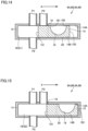
- each of first three-way valve 8A, second three-way valve 9A, third three-way valve 8B, and fourth three-way valve 9B described above can also be in the three states, i.e., the first state, the second state, and the third state as with each of first three-way valve 8A, second three-way valve 9A, third three-way valve 8B, and fourth three-way valve 9B shown in Figs. 2 to 7 . Therefore, refrigeration cycle apparatus 1000 including first three-way valve 8A, second three-way valve 9A, third three-way valve 8B, and fourth three-way valve 9B shown in Figs. 14 to 16 can also exhibit the same effect as that of refrigeration cycle apparatus 1000 including first three-way valve 8A, second three-way valve 9A, third three-way valve 8B, and fourth three-way valve 9B shown in Figs. 2 to 7 .
- Refrigeration cycle apparatus 1000 may further include an apparatus configured to prevent liquid from returning to compressor 1.
- an apparatus configured to prevent liquid from returning to compressor 1.
- Examples of such an apparatus include an accumulator or a heat exchanger configured to exchange heat between the refrigerant discharged from compressor 1 and the refrigerant suctioned into compressor 1.
Landscapes
- Engineering & Computer Science (AREA)
- Physics & Mathematics (AREA)
- Mechanical Engineering (AREA)
- Thermal Sciences (AREA)
- General Engineering & Computer Science (AREA)
- Fluid Mechanics (AREA)
- Compression-Type Refrigeration Machines With Reversible Cycles (AREA)
- Multiple-Way Valves (AREA)
- Sliding Valves (AREA)
Abstract
Description
- The present disclosure relates to a refrigeration cycle apparatus.
- Conventionally, there has been known a refrigeration cycle apparatus including an outdoor unit, a plurality of indoor units, and a branch unit, wherein the outdoor unit and the plurality of indoor units are connected via the branch unit.
-
Japanese Patent Laying-Open No. 4-6361 - The first flow path switching mechanism includes one four-way valve and four check valves. The first refrigerant flow path mechanism switches between a cooling operation state in which the outdoor heat exchanger acts as a condenser and a heating operation state in which the outdoor heat exchanger acts as an evaporator, and a state in which the pressure of the refrigerant flowing through the first refrigerant pipe is lower than the pressure of the refrigerant flowing through the second refrigerant pipe is maintained irrespective of the switching between the cooling operation state and the heating operation state. The inner diameter of the first refrigerant pipe is larger than the inner diameter of the second refrigerant pipe. Thus, in the refrigeration cycle apparatus, pressure loss in the first refrigerant pipe and the second refrigerant pipe is suppressed from being increased due to the switching between the cooling operation state and the heating operation state, thereby suppressing decreased operation capability.
- The second flow path switching mechanism includes a plurality of flow path switching valves. In the first operation state or the second operation state, the second refrigerant flow path mechanism switches between a full-cooling operation state or full-heating operation state in which all of the plurality of indoor units each act as an evaporator or condenser and a cooling-dominated operation state or heating-dominated operation in which part of the plurality of indoor units each act as a condenser and the other part of the plurality of indoor units each act as an evaporator.
- PTL 1:
Japanese Patent Laying-Open No. 4-6361 - In the above-described refrigeration cycle apparatus, when load of an indoor heat exchanger is decreased, an amount of circulation of the refrigerant needs to be decreased by decreasing the driving frequency of the compressor in order to prevent decreased comfortability.
- However, in the refrigeration cycle apparatus, when the amount of circulation of the refrigerant is decreased, a differential pressure before and after a check valve included in the first flow path switching mechanism is decreased, thus resulting in occurrence of chattering.
- It is a main object of the present disclosure to provide a refrigeration cycle apparatus so as to suppress occurrence of chattering while preventing decreased comfortability when load of an indoor heat exchanger is decreased.
- A refrigeration cycle apparatus according to the present disclosure comprises a refrigerant circuit in which refrigerant circulates, the refrigerant circuit comprising a compressor, a flow path switching portion, an outdoor heat exchanger, a decompressing apparatus, a first indoor heat exchanger, a first connecting pipe through which the refrigerant flows into the first indoor heat exchanger, and a second connecting pipe through which the refrigerant flows from the first indoor heat exchanger. The flow path switching portion is configured to switch between a cooling operation state in which the outdoor heat exchanger acts as a condenser and a heating operation state in which the outdoor heat exchanger acts as an evaporator. The refrigerant circuit further comprises: a first three-way valve arranged downstream of the first indoor heat exchanger in the cooling operation state and arranged upstream of the first indoor heat exchanger in the heating operation state; and a second three-way valve arranged upstream of the first indoor heat exchanger in the cooling operation state and arranged downstream of the first indoor heat exchanger in the heating operation state. Each of the first three-way valve and the second three-way valve comprises: a valve seat having a valve chamber and provided with a first aperture, a second aperture and a third aperture, the first aperture, the second aperture, and the third aperture being connected to the valve chamber; and a valve body configured to move among a first position, a second position, and a third position in the valve chamber. The first aperture of each of the first three-way valve and the second three-way valve is connected to one end or the other end of the first indoor heat exchanger in the refrigerant circuit. The second aperture of each of the first three-way valve and the second three-way valve is connected to the first connecting pipe. The third aperture of each of the first three-way valve and the second three-way valve is connected to the second connecting pipe. Each of the first three-way valve and the second three-way valve is configured to be switched independently to one of a first state in which the valve body is located at the first position, a second state in which the valve body is located at the second position, and a third state in which the valve body is located at the third position. In each of the first three-way valve and the second three-way valve, in the first state, a first space is arranged in the valve chamber, the first space communicating with the first aperture and the second aperture and being separated from the third aperture, in the second state, a second space is arranged in the valve chamber, the second space communicating with the first aperture, the second aperture, and the third aperture, and in the third state, a third space is arranged in the valve chamber, the third space communicating with the first aperture and the third aperture and being separated from the second aperture.
- According to the present disclosure, a refrigeration cycle apparatus can be provided to suppress occurrence of chattering while preventing decreased comfortability when load of an indoor heat exchanger is decreased.
-
-
Fig. 1 is a diagram showing a refrigerant circuit of a refrigeration cycle apparatus according to the present embodiment. -
Fig. 2 is a cross sectional view showing a valve seat, a valve chamber, and a valve body when a first three-way valve according to the present embodiment is in a first state. -
Fig. 3 is a cross sectional view when viewed from an arrow III-III shown inFig. 2 . -
Fig. 4 is a cross sectional view showing the valve seat, the valve chamber, and the valve body when the first three-way valve according to the present embodiment is in a second state. -
Fig. 5 is a cross sectional view when viewed from an arrow V-V shown inFig. 4 . -
Fig. 6 is a cross sectional view showing the valve seat, the valve chamber, and the valve body when the first three-way valve according to the present embodiment is in a third state. -
Fig. 7 is a cross sectional view when viewed from an arrow VII-VII shown inFig. 6 . -
Fig. 8 is a diagram showing the refrigerant circuit when the refrigeration cycle apparatus according to the present embodiment is in a full-cooling operation state. -
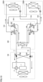
Fig. 9 is a diagram showing the refrigerant circuit when load of a first indoor heat exchanger is decreased to be lower than that in the state shown inFig. 8 when the refrigeration cycle apparatus according to the present embodiment is in a full-cooling operation state. -
Fig. 10 is a diagram showing the refrigerant circuit when the refrigeration cycle apparatus according to the present embodiment is in a full-heating operation state. -
Fig. 11 is a diagram showing the refrigerant circuit when the load of the first indoor heat exchanger is decreased to be lower than that in the state shown inFig. 10 when the refrigeration cycle apparatus according to the present embodiment is in the full-heating operation state. -
Fig. 12 is a diagram showing the refrigerant circuit when the refrigeration cycle apparatus according to the present embodiment is in a first cooling-dominated operation state. -
Fig. 13 is a diagram showing the refrigerant circuit when the refrigeration cycle apparatus according to the present embodiment is in a first heating-dominated operation state. -
Fig. 14 is a cross sectional view showing a valve seat, a valve chamber, and a valve body when a modification of the first three-way valve shown inFig. 2 is in the first state. -
Fig. 15 is a cross sectional view showing the valve seat, the valve chamber, and the valve body when the modification of the first three-way valve shown inFig. 2 is in the second state. -
Fig. 16 is a cross sectional view showing the valve seat, the valve chamber, and the valve body when the modification of the first three-way valve shown inFig. 2 is in the third state. - Hereinafter, embodiments will be described with reference to figures. It should be noted that in the below-described figures, the same or corresponding portions are denoted by the same reference characters, and will not be described repeatedly.
- As shown in
Fig. 1 , a refrigeration cycle apparatus 1000 according to the present embodiment includes a refrigerant circuit in which refrigerant circulates. The refrigerant circuit includes acompressor 1, a four-way valve 2 serving as a flow path switching portion, anoutdoor heat exchanger 3, a firstdecompressing apparatus 4A, a seconddecompressing apparatus 4B, a firstindoor heat exchanger 5A, a secondindoor heat exchanger 5B, afirst check valve 6A, asecond check valve 6B, athird check valve 6C, afourth check valve 6D, a gas-liquid separator 7, a first three-way valve 8A, a second three-way valve 9A, a third three-way valve 8B, a fourth three-way valve 9B, a first connectingpipe 10, a second connectingpipe 11, a third connectingpipe 12A, a fourth connectingpipe 13A, a fifth connectingpipe 12B, and a sixth connectingpipe 13B. -
Compressor 1, four-way valve 2,outdoor heat exchanger 3,first check valve 6A,second check valve 6B,third check valve 6C, andfourth check valve 6D are accommodated in anoutdoor unit 100. First decompressingapparatus 4A and firstindoor heat exchanger 5A are accommodated in a firstindoor unit 200A. Seconddecompressing apparatus 4B and secondindoor heat exchanger 5B are accommodated in a secondindoor unit 200B. Gas-liquid separator 7, first three-way valve 8A, second three-way valve 9A, third three-way valve 8B, and fourth three-way valve 9B are accommodated in abranch unit 300. - First connecting
pipe 10 and second connectingpipe 11 are arranged betweenoutdoor unit 100 andbranch unit 300 so as to connectoutdoor unit 100 andbranch unit 300 to each other. Third connectingpipe 12A and fourth connectingpipe 13A are arranged between firstindoor unit 200A andbranch unit 300 so as to connect firstindoor unit 200A andbranch unit 300 to each other. Fifth connectingpipe 12B and sixth connectingpipe 13B are arranged between secondindoor unit 200B andbranch unit 300 so as to connect secondindoor unit 200B andbranch unit 300 to each other. -
Compressor 1 has a discharge port through which the refrigerant is discharged and a suction port through which the refrigerant is suctioned.Compressor 1 is, for example, a constant-speed compressor having a constant driving frequency. It should be noted thatcompressor 1 may be, for example, an inverter compressor having a driving frequency controlled by an inverter. - Four-
way valve 2 has first to fourth ports. The first port is connected to the discharge port ofcompressor 1. The second port is connected to the suction port ofcompressor 1. The third port is connected to first connectingpipe 10 viaoutdoor heat exchanger 3 andfirst check valve 6A, and is connected to second connectingpipe 11 viaoutdoor heat exchanger 3 andsecond check valve 6B. The fourth port is connected to first connectingpipe 10 viathird check valve 6C, and is connected to second connectingpipe 11 viafourth check valve 6D. Four-way valve 2 switches between a cooling operation state in which the first port communicates with the third port and the second port communicates with the fourth port and a heating operation state in which the first port communicates with the fourth port and the second port communicates with the third port. - In
outdoor heat exchanger 3, heat is exchanged between the refrigerant circulating in the refrigerant circuit and outdoor air. First decompressingapparatus 4A andsecond decompressing apparatus 4B are, for example, expansion valves. In each offirst decompressing apparatus 4A andsecond decompressing apparatus 4B, the refrigerant is expanded. In each of firstindoor heat exchanger 5A and secondindoor heat exchanger 5B, heat is exchanged between the refrigerant circulating in the refrigerant circuit and indoor air. Firstindoor unit 200A and secondindoor unit 200B are installed, for example, in different rooms. -
Outdoor unit 100 is provided with: a refrigerant flow path that connects betweenoutdoor heat exchanger 3 and first connectingpipe 10; a refrigerant flow path that connects betweenoutdoor heat exchanger 3 and second connectingpipe 11; a refrigerant flow path that connects between the fourth port of four-way valve 2 and first connectingpipe 10; and a refrigerant flow path that connects between the fourth port of four-way valve 2 and second connectingpipe 11. -
First check valve 6A is arranged in the refrigerant flow path betweenoutdoor heat exchanger 3 and first connectingpipe 10, and permits only the flow of the refrigerant fromoutdoor heat exchanger 3 to first connectingpipe 10.First check valve 6A blocks the flow of the refrigerant from first connectingpipe 10 tooutdoor heat exchanger 3. -
Second check valve 6B is arranged in the refrigerant flow path betweenoutdoor heat exchanger 3 and second connectingpipe 11, and permits only the flow of the refrigerant from second connectingpipe 11 to the outdoor heat exchanger.Second check valve 6B blocks the flow of the refrigerant from second connectingpipe 11 tooutdoor heat exchanger 3. -
Third check valve 6C is arranged in the refrigerant flow path between the fourth port of four-way valve 2 and first connectingpipe 10, and permits only the flow of the refrigerant from the fourth port of four-way valve 2 to the second connecting pipe.Third check valve 6C blocks the flow of the refrigerant from first connectingpipe 10 to the fourth port of four-way valve 2. -
Fourth check valve 6D is arranged in the refrigerant flow path between the fourth port of four-way valve 2 and second connectingpipe 11, and permits only the flow of the refrigerant from second connectingpipe 11 to the fourth port of four-way valve 2.Fourth check valve 6D blocks the flow of the refrigerant from the fourth port of four-way valve 2 to second connectingpipe 11. - Gas-
liquid separator 7 is connected to first connectingpipe 10 and has anflow inlet 71 via which the refrigerant flows in, afirst flow outlet 72 via which the gas-phase refrigerant flows out, and asecond flow outlet 73 via which the liquid-phase refrigerant flows out. - First three-
way valve 8A, second three-way valve 9A, third three-way valve 8B, and fourth three-way valve 9B have the same configuration. As shown inFigs. 2 to 7 , each of first three-way valve 8A, second three-way valve 9A, third three-way valve 8B, and fourth three-way valve 9B includes avalve seat 14 and avalve body 15. - Each of
valve seats 14 of first three-way valve 8A, second three-way valve 9A, third three-way valve 8B, and fourth three-way valve 9B includes avalve chamber 16 and is provided with a first aperture P1, a second aperture P2, and a third aperture P3, first aperture P1, second aperture P2, and third aperture P3 communicating withvalve chamber 16. -
Valve seat 14 has afirst surface 14A facingvalve chamber 16 and provided with one end of each of first aperture P1 and third aperture P3, and asecond surface 14B provided with one end of second aperture P2. First aperture P1 is arranged beside third apertures P3 with an interval being interposed therebetween in a peripheral direction serving as a first direction. The aperture area of third aperture P3 is equal to, for example, the aperture area of first aperture P1.Second surface 14B facesfirst surface 14A withvalve body 15 being interposed therebetween in a Z direction serving as a second direction, for example. Second aperture P2 is arranged to overlap with the rotation axis ofvalve body 15 when viewed in the Z direction, for example. When viewed in the Z direction, the shortest distance between the respective centers of second aperture P2 and first aperture P1 is equal to, for example, the shortest distance between the respective centers of second aperture P2 and third aperture P3. - First aperture P1 of first three-
way valve 8A is connected to firstindoor heat exchanger 5A via third connectingpipe 12A. Second aperture P2 of first three-way valve 8A is connected tofirst flow outlet 72 of gas-liquid separator 7. That is, second aperture P2 of first three-way valve 8A is connected to first connectingpipe 10 via gas-liquid separator 7. Third aperture P3 of first three-way valve 8A is connected to second connectingpipe 11. - First aperture P1 of second three-
way valve 9A is connected to firstindoor heat exchanger 5A via fourth connectingpipe 13A. Second aperture P2 of second three-way valve 9A is connected tosecond flow outlet 73 of gas-liquid separator 7. That is, second aperture P2 of second three-way valve 9A is connected to first connectingpipe 10 via gas-liquid separator 7. Third aperture P3 of second three-way valve 9A is connected to second connectingpipe 11. - First aperture P1 of third three-
way valve 8B is connected to secondindoor heat exchanger 5B via fifth connectingpipe 12B. Second aperture P2 of third three-way valve 8B is connected tofirst flow outlet 72 of gas-liquid separator 7. That is, second aperture P2 of third three-way valve 8B is connected to first connectingpipe 10 via gas-liquid separator 7. Third aperture P3 of third three-way valve 8B is connected to second connectingpipe 11. - First aperture P1 of fourth three-
way valve 9B is connected to secondindoor heat exchanger 5B via sixth connectingpipe 13B. Second aperture P2 of fourth three-way valve 9B is connected tosecond flow outlet 73 of gas-liquid separator 7. That is, second aperture P2 of fourth three-way valve 9B is connected to first connectingpipe 10 via gas-liquid separator 7. Third aperture P3 of fourth three-way valve 9B is connected to second connectingpipe 11. - Second aperture P2 of first three-
way valve 8A and second aperture P2 of third three-way valve 8B are connected tofirst flow outlet 72 of gas-liquid separator 7 and first connectingpipe 10 in parallel with each other. Third aperture P3 of first three-way valve 8A and third aperture P3 of third three-way valve 8B are connected to second connectingpipe 11 in parallel with each other. - Second aperture P2 of second three-
way valve 9A and second aperture P2 of fourth three-way valve 9B are connected tosecond flow outlet 73 of gas-liquid separator 7 and first connectingpipe 10 in parallel with each other. Third aperture P3 of second three-way valve 9A and third aperture P3 of fourth three-way valve 9B are connected to second connectingpipe 11 in parallel with each other. - Each of
valve bodies 15 of first three-way valve 8A, second three-way valve 9A, third three-way valve 8B, and fourth three-way valve 9B moves among a first position, a second position, and a third position invalve chamber 16.Valve body 15 is provided to rotate about, for example, a rotation axis extending along the Z direction.Valve body 15 rotates, for example, in a peripheral direction from third aperture P3 toward first aperture P1 and in a direction opposite thereto.Valve body 15 is connected to a rotation shaft of a motor (not shown) via, for example, agear 17.Valve body 15 has athird surface 18 slidable onfirst surface 14A, and is provided with arecess 19 arranged besidethird surface 18 in the peripheral direction serving as the first direction and recessed with respect tothird surface 18, and has afourth surface 20 located opposite tothird surface 18 and facingsecond surface 14B ofvalve seat 14 with an interval being interposed therebetween in the Z direction. -
Valve body 15 has: afirst end portion 151 in the peripheral direction; and asecond end portion 152 located opposite tofirst end portion 151 in the peripheral direction.First end portion 151 is an end portion arranged on the front side with respect tosecond end portion 152 whenvalve body 15 rotates in the peripheral direction from third aperture P3 toward first aperture P1.Second end portion 152 is an end portion arranged on the front side with respect tofirst end portion 151 whenvalve body 15 rotates in the peripheral direction from first aperture P1 toward third aperture P3. -
Recess 19 has: athird end portion 191 in the peripheral direction; and afourth end portion 192 located opposite tothird end portion 191 in the peripheral direction.Third end portion 191 is an end portion arranged on the rear side with respect tofirst end portion 151 and on the front side with respect tofourth end portion 192 whenvalve body 15 rotates in the peripheral direction from third aperture P3 toward first aperture P1.Fourth end portion 192 is an end portion arranged on the rear side with respect tosecond end portion 152 and on the front side with respect tothird end portion 191 whenvalve body 15 rotates in the peripheral direction from first aperture P1 toward third aperture P3. - An interval between
first end portion 151 andthird end portion 191 in the peripheral direction is wider than an interval betweensecond end portion 152 andfourth end portion 192 in the peripheral direction.Third surface 18 is arranged at least betweenfirst end portion 151 andthird end portion 191 and around the entire periphery ofrecess 19 in the peripheral direction. - As shown in
Fig. 4 , whenvalve body 15 is located at the second position,valve body 15 is provided not to overlap with at least a portion of each of first aperture P1 and third aperture P3 when viewed from the second aperture P2 side. As indicated by a dotted line inFig. 4 , whenvalve body 15 is located at the second position,valve body 15 is provided not to overlap with, for example, first aperture P1 and third aperture P3 when viewed from the second aperture P2 side.Valve body 15 is provided to allow second space S2 to be continuous to a whole of each of first aperture P1 and third aperture P3. When viewed from the second aperture P2 side, an angle θ1 formed with respect to the rotation axis byfirst end portion 151 andsecond end portion 152 ofvalve body 15 outsidevalve body 15 is equal to, for example, an angle θ2 formed with respect to the rotation axis by a first imaginary line L1 passing through the rotation axis ofvalve body 15 and tangent to first aperture P1 and a second imaginary line L2 passing through the rotation axis ofvalve body 15 and tangent to third aperture P3. - As shown in
Fig. 6 , when viewed from the second aperture P2 side,recess 19 is provided to overlap with a whole of each of first aperture P1 and third aperture P3 whenvalve body 15 is located at the third position. An angle θ3 formed with respect to the rotation axis bythird end portion 191 andfourth end portion 192 ofrecess 19 is equal to, for example, angle θ2 described above. - Each of first three-
way valve 8A, second three-way valve 9A, third three-way valve 8B, and fourth three-way valve 9B can be in the following three states: a first state in whichvalve body 15 is located at the first position; a second state in whichvalve body 15 is located at the second position; and a third state in whichvalve body 15 is located at the third position. Each of first three-way valve 8A, second three-way valve 9A, third three-way valve 8B, and fourth three-way valve 9B is switchable independently to one of the above-described three states. - As shown in
Figs. 2 and 3 , in the first state, a first space S1 communicating with first aperture P1 and second aperture P2 and separated from third aperture P3 byvalve body 15 is arranged in eachvalve chamber 16. In the first state,valve body 15 does not overlap with first aperture P1 in the Z direction.Third surface 18 ofvalve body 15 overlaps with a whole of third aperture P3, and closes third aperture P3.Recess 19 ofvalve body 15 does not overlap with first aperture P1 and third aperture P3.Third surface 18 is arranged to overlap with a whole of third aperture P3 when viewed from the second aperture P2 side.First end portion 151 andthird end portion 191 ofvalve body 15 are arranged to sandwich third aperture P3 therebetween in the peripheral direction when viewed from the second aperture P2 side.Recess 19 is arranged not to overlap with first aperture P1 and third aperture P3 when viewed from the second aperture P2 side. - As shown in
Figs. 4 and 5 , in the second state, second space S2 communicating with first aperture P1, second aperture P2, and third aperture P3 is arranged invalve chamber 16. The second space forms a branched flow path or a merged flow path. - In the second state,
valve body 15 does not overlap with first aperture P1 in the Z direction.Valve body 15 does not overlap with at least a portion of third aperture P3 in the Z direction.Valve body 15 is arranged, for example, at a second position indicated by a solid line inFig. 4 . In this case, for example,third surface 18 is arranged to overlap with only a portion of third aperture P3 when viewed from the second aperture P2 side. When viewed from the second aperture P2 side, the aperture area of the region of third aperture P3 which does not overlap withvalve body 15 is smaller than the aperture area of first aperture P1, for example. -
Valve body 15 may be arranged, for example, at the second position indicated by a dotted line inFig. 4 . In this case, for example,third surface 18 is arranged not to overlap with third aperture P3 when viewed from the second aperture P2 side. - As shown in
Figs. 6 and 7 , in the third state, a third space S3 communicating with first aperture P1 and third aperture P3 and separated from second aperture P2 is arranged inrecess 19 ofvalve body 15. In the third state,recess 19 ofvalve body 15 is arranged to overlap with first aperture P1 and third aperture P3 in the Z direction. - Refrigeration cycle apparatus 1000 is switched by four-
way valve 2 between a cooling operation state in whichoutdoor heat exchanger 3 acts as a condenser and a heating operation state in whichoutdoor heat exchanger 3 acts as an evaporator. Further, refrigeration cycle apparatus 1000 is switched by first three-way valve 8A, second three-way valve 9A, third three-way valve 8B, and fourth three-way valve 9B to a full-cooling operation state, a cooling-dominated operation state, a full-heating operation state, or a heating-dominated operation. - In the full-cooling operation state, refrigeration cycle apparatus 1000 is switched among a first full-cooling operation state shown in
Fig. 8 , a second full-cooling operation state shown inFig. 9 , and a third full-cooling operation state not shown. Similarly, in the full-heating operation state, refrigeration cycle apparatus 1000 is switched among a first full-heating operation state shown inFig. 10 , a second full-heating operation state shown inFig. 11 , and a third full-heating operation state not shown. - The first full-cooling operation state shown in
Fig. 8 is realized when each of loads of firstindoor heat exchanger 5A and secondindoor heat exchanger 5B is comparatively high. In the first full-cooling operation state shown inFig. 8 , each of first three-way valve 8A and third three-way valve 8B is in the third state, and each of second three-way valve 9A and fourth three-way valve 9B is in the first state. In the first full-cooling operation state shown inFig. 8 , the refrigerant flows in the refrigerant circuit along arrows inFig. 8 . - High-pressure gas-phase refrigerant discharged from
compressor 1 is condensed inoutdoor heat exchanger 3 into high-pressure liquid-phase refrigerant or gas-liquid two-phase refrigerant, and flows out to first connectingpipe 10. The high-pressure liquid-phase refrigerant or gas-liquid two-phase refrigerant having flowed through first connectingpipe 10 flows into gas-liquid separator 7 viaflow inlet 71. The high-pressure liquid-phase refrigerant having flowed out fromsecond flow outlet 73 is branched inbranch unit 300, reaches each of second apertures P2 of second three-way valve 9A and fourth three-way valve 9B that are in the first state, flows through each of the first spaces, and flows out from each of first apertures P1 to fourth connectingpipe 13A or sixth connectingpipe 13B. The liquid-phase refrigerant having flowed through fourth connectingpipe 13A is decompressed by first decompressingapparatus 4A, is then evaporated in firstindoor heat exchanger 5A, and flows out to third connectingpipe 12A as low-pressure gas-phase refrigerant. The liquid-phase refrigerant having flowed through sixth connectingpipe 13B is decompressed bysecond decompressing apparatus 4B, is then evaporated in secondindoor heat exchanger 5B, and flows out to fifth connectingpipe 12B as low-pressure gas-phase refrigerant. The low-pressure gas-phase refrigerant having flowed through third connectingpipe 12A or fifth connectingpipe 12B reaches first apertures P1 of first three-way valve 8A and third three-way valve 8B that are in the third state, flows through each of the third spaces, and then flows out from third apertures P3. The flows of the gas-phase refrigerant from third apertures P3 are merged inbranch unit 300 and the gas-phase refrigerant flows out to second connectingpipe 11. - Thus, in the first full-cooling operation state shown in
Fig. 8 , the refrigerant discharged fromcompressor 1 flows through one of firstindoor heat exchanger 5A and secondindoor heat exchanger 5B, and is then suctioned intocompressor 1. - The second full-cooling operation state shown in
Fig. 9 is realized when only the load of firstindoor heat exchanger 5A becomes lower than a predetermined value, for example. It should be noted that the load of secondindoor heat exchanger 5B in the second full-cooling operation state may be decreased to be lower than the load of secondindoor heat exchanger 5B in the first full-cooling operation state. - In the second full-cooling operation state shown in
Fig. 9 , each of first three-way valve 8A and third three-way valve 8B is in the third state, fourth three-way valve 9B is in the first state, and second three-way valve 9A is in the second state. That is, the second full-cooling operation state shown inFig. 9 is different from the first full-cooling operation state shown inFig. 8 only in that second three-way valve 9A is in the second state. In the second full-cooling operation state shown inFig. 9 , the refrigerant flows in the refrigerant circuit along arrows inFig. 9 . - The high-pressure liquid-phase refrigerant having flowed out from
second flow outlet 73 is branched inbranch unit 300, and part of the high-pressure liquid-phase refrigerant reaches second aperture P2 of second three-way valve 9A that is in the second state. The high-pressure liquid-phase refrigerant having flowed into second aperture P2 of second three-way valve 9A flows through the second space and is accordingly further branched invalve chamber 16. The part of the high-pressure liquid-phase refrigerant having flowed into second aperture P2 of second three-way valve 9A flows out from third aperture P3. The liquid-phase refrigerant having flowed out from third aperture P3 of second three-way valve 9A is merged with the low-pressure gas-phase refrigerant having flowed out from each of third apertures P3 of first three-way valve 8A and third three-way valve 8B inbranch unit 300, and flows out to second connectingpipe 11. The remainder of the high-pressure liquid-phase refrigerant having flowed into second aperture P2 flows out from first aperture P1 to fourth connectingpipe 13A, is decompressed by first decompressingapparatus 4A, and is then evaporated in firstindoor heat exchanger 5A. - In the second full-cooling operation state shown in
Fig. 9 , an amount of refrigerant flowing through firstindoor heat exchanger 5A is controlled as a ratio of the aperture areas of first aperture P1 and third aperture P3 when viewed from the second aperture P2 side of second three-way valve 9A. The ratio is controlled as a rotation angle ofvalve body 15 of second three-way valve 9A. - The switching between the first full-cooling operation state shown in
Fig. 8 and the second full-cooling operation state shown inFig. 9 and the control of the rotation angle ofvalve body 15 of second three-way valve 9A in the second full-cooling operation state shown inFig. 9 are performed to bring the evaporation temperature in firstindoor heat exchanger 5A into a target evaporation temperature, for example. When it is determined that the evaporation temperature in firstindoor heat exchanger 5A is lower than the target evaporation temperature,valve body 15 of second three-way valve 9A rotates from the first position to the second position. The evaporation temperature is always or regularly measured by a temperature sensor (not shown) attached to firstindoor heat exchanger 5A, for example. The determination of the evaporation temperature and the control of the rotation angle ofvalve body 15 are always or regularly performed bycontrol unit 310, for example. When switching is made between the first full-cooling operation state and the second full-cooling operation state, the driving frequency ofcompressor 1 is constant, for example. Here, the expression "the driving frequency is constant" means that the maximum value and minimum value of the driving frequency fall within a range of 95% or more and 105% or less of the average value thereof. - Thus, in the second full-cooling operation state shown in
Fig. 9 , part of the refrigerant discharged fromcompressor 1 is suctioned intocompressor 1 without flowing through one of firstindoor heat exchanger 5A and secondindoor heat exchanger 5B. Therefore, the flow rate of the refrigerant flowing in firstindoor heat exchanger 5A in the second full-cooling operation state shown inFig. 9 becomes lower than the flow rate of the refrigerant flowing in firstindoor heat exchanger 5A in the first full-cooling operation state shown inFig. 8 without decreasing the driving frequency ofcompressor 1. - It should be noted that the switching between the first full-cooling operation state shown in
Fig. 8 and the second full-cooling operation state shown inFig. 9 and the control of the rotation angle ofvalve body 15 of second three-way valve 9A in the second full-cooling operation state shown inFig. 9 may be performed when a difference between the evaporation temperature of firstindoor heat exchanger 5A and the target evaporation temperature falls out of a predetermined range. - The third full-cooling operation state is realized, for example, when only the load of second
indoor heat exchanger 5B becomes lower than a predetermined value. In the third full-cooling operation state, each of first three-way valve 8A and third three-way valve 8B is in the third state, second three-way valve 9A is in the first state, and fourth three-way valve 9B is in the second state. The flow rate of the refrigerant flowing in secondindoor heat exchanger 5B in the third full-cooling operation state becomes lower than the flow rate of the refrigerant flowing in secondindoor heat exchanger 5B in the first full-cooling operation state shown inFig. 8 . - The first full-heating operation state shown in
Fig. 10 is realized when each of loads of firstindoor heat exchanger 5A and secondindoor heat exchanger 5B is comparatively high. In the first full-heating operation state shown inFig. 10 , each of first three-way valve 8A and third three-way valve 8B is in the first state, and each of second three-way valve 9A and fourth three-way valve 9B is in the third state. In the first full-heating operation state shown inFig. 10 , the refrigerant flows in the refrigerant circuit along arrows inFig. 10 . - High-pressure gas-phase refrigerant discharged from
compressor 1 flows out to first connectingpipe 10 throughthird check valve 6C. The high-pressure gas-phase refrigerant having flowed through first connectingpipe 10 flows into gas-liquid separator 7 viaflow inlet 71. The high-pressure gas-phase refrigerant having flowed out fromfirst flow outlet 72 is branched inbranch unit 300, reaches each of second apertures P2 of first three-way valve 8A and third three-way valve 8B that are in the first state, flows through each of the first spaces, and flows out from each of first apertures P1 to third connectingpipe 12A or fifth connectingpipe 12B. The gas-phase refrigerant having flowed through third connectingpipe 12A is condensed in firstindoor heat exchanger 5A, is then decompressed by first decompressingapparatus 4A, and flows out to fourth connectingpipe 13A as low-pressure gas-liquid two-phase refrigerant. The gas-phase refrigerant having flowed through fifth connectingpipe 12B is condensed in secondindoor heat exchanger 5B, is then decompressed bysecond decompressing apparatus 4B, and flows out to sixth connectingpipe 13B as low-pressure gas-liquid two-phase refrigerant. The low-pressure gas-phase refrigerant having flowed through fourth connectingpipe 13A or sixth connectingpipe 13B reaches first apertures P1 of second three-way valve 9A and fourth three-way valve 9B that are in the third state, flows through each of the third spaces, and then flows out from third apertures P3. The flows of the gas-phase refrigerant from third apertures P3 are merged inbranch unit 300 and the gas-phase refrigerant flows out to second connectingpipe 11. - Thus, in the first full-heating operation state shown in
Fig. 10 , the refrigerant discharged fromcompressor 1 flows through one of firstindoor heat exchanger 5A and secondindoor heat exchanger 5B, and is then suctioned intocompressor 1. - The second full-heating operation state shown in
Fig. 11 is realized, for example, when only the load of firstindoor heat exchanger 5A becomes lower than a predetermined value. It should be noted that the load of secondindoor heat exchanger 5B in the second full-heating operation state shown inFig. 11 may be decreased to be lower than that in the first full-heating operation state. - In the second full-heating operation state shown in
Fig. 11 , each of second three-way valve 9A and fourth three-way valve 9B is in the third state, third three-way valve 8B is in the first state, and first three-way valve 8A is in the second state. That is, the second full-heating operation state shown inFig. 11 is different from the first full-heating operation state shown inFig. 10 only in that first three-way valve 8A is in the second state. In the second full-heating operation state shown inFig. 11 , the refrigerant flows in the refrigerant circuit along arrows inFig. 11 . - High-pressure gas-phase refrigerant having flowed out from
first flow outlet 72 is branched inbranch unit 300, and part of the high-pressure gas-phase refrigerant reaches second aperture P2 of first three-way valve 8A that is in the second state. The high-pressure gas-phase refrigerant having flowed into second aperture P2 of first three-way valve 8A flows through the second space and is accordingly further branched invalve chamber 16. Part of the high-pressure gas-phase refrigerant having flowed into second aperture P2 of first three-way valve 8A flows out from third aperture P3. The gas-phase refrigerant having flowed out from third aperture P3 of first three-way valve 8A is merged with the low-pressure gas-phase refrigerant having flowed out from each of third apertures P3 of second three-way valve 9A and fourth three-way valve 9B inbranch unit 300, and flows out to second connectingpipe 11. The remainder of the high-pressure gas-phase refrigerant having flowed into second aperture P2 flows out from first aperture P1 to third connectingpipe 12A, and is condensed in firstindoor heat exchanger 5A. - In the second full-heating operation state shown in
Fig. 11 , an amount of refrigerant flowing through firstindoor heat exchanger 5A is controlled by first three-way valve 8A. The amount of refrigerant flowing through firstindoor heat exchanger 5A becomes smaller as the ratio of the aperture area of third aperture P3 to the aperture area of first aperture P1 of first three-way valve 8A is higher. The ratio is controlled as a rotation angle ofvalve body 15 of first three-way valve 8A. - The switching between the first full-heating operation state shown in
Fig. 10 and the second full-heating operation state shown inFig. 11 , and the control of the rotation angle ofvalve body 15 of first three-way valve 8A in the second full-heating operation state shown inFig. 11 are performed to bring the condensation temperature in firstindoor heat exchanger 5A into a target condensation temperature, for example. When it is determined that the condensation temperature in firstindoor heat exchanger 5A is higher than the target condensation temperature,valve body 15 of first three-way valve 8A rotates from the first position to the second position. The condensation temperature is always or regularly measured by a temperature sensor (not shown) attached to firstindoor heat exchanger 5A, for example. The determination of the condensation temperature and the control of the rotation angle ofvalve body 15 are always or regularly performed bycontrol unit 310, for example. When switching is made between the first full-heating operation state and the second full-heating operation state, the driving frequency ofcompressor 1 is constant, for example. - Thus, in the second full-heating operation state shown in
Fig. 11 , part of the refrigerant discharged fromcompressor 1 is suctioned intocompressor 1 without flowing through one of firstindoor heat exchanger 5A and secondindoor heat exchanger 5B. Therefore, the flow rate of the refrigerant flowing in firstindoor heat exchanger 5A in the second full-heating operation state shown inFig. 11 is lower than the flow rate of the refrigerant flowing in firstindoor heat exchanger 5A in the first full-heating operation state shown inFig. 10 without decreasing the driving frequency ofcompressor 1. - It should be noted that the switching between the first full-heating operation state shown in
Fig. 10 and the second full-heating operation state shown inFig. 11 and the control of the rotation angle ofvalve body 15 of first three-way valve 8A in the second full-heating operation state shown inFig. 11 may be performed when a difference between the condensation temperature of firstindoor heat exchanger 5A and the target condensation temperature falls out of a predetermined range. - The third full-heating operation state is realized, for example, when only the load of second
indoor heat exchanger 5B becomes lower than a predetermined value. In the third full-heating operation state, each of second three-way valve 9A and fourth three-way valve 9B is in the third state, first three-way valve 8A is in the first state, and third three-way valve 8B is in the second state. The flow rate of the refrigerant flowing in secondindoor heat exchanger 5B in the third full-heating operation state becomes lower than the flow rate of the refrigerant flowing in secondindoor heat exchanger 5B in the first full-heating operation state shown inFig. 10 . - Thus, in refrigeration cycle apparatus 1000, when the load of one of first
indoor heat exchanger 5A and secondindoor heat exchanger 5B is decreased in the first full-cooling operation state, the second full-cooling operation state or the third full-cooling operation state is realized. Similarly, in refrigeration cycle apparatus 1000, when the load of one of firstindoor heat exchanger 5A and secondindoor heat exchanger 5B is decreased in the first full-heating operation state, the second full-heating operation state or the third full-heating operation state is realized. As a result, in refrigeration cycle apparatus 1000, the flow rate of the refrigerant flowing in the indoor heat exchanger in which the load is decreased can be decreased without decreasing the driving frequency ofcompressor 1, thereby suppressing occurrence of chattering infirst check valve 6A,second check valve 6B,third check valve 6C, andfourth check valve 6D while preventing decreased comfortability in the rooms in which the indoor units are arranged. - It should be noted that the switching among the full-cooling operation state, the cooling-dominated operation state, the full-heating operation state, and the heating-dominated operation state can be realized also when each of first three-
way valve 8A, second three-way valve 9A, third three-way valve 8B, and fourth three-way valve 9B is replaced with two or more electromagnetic valves (for example, eight electromagnetic valves). In this case, the control unit needs to control movement of each of the valve bodies of the eight electromagnetic valves for the purpose of the switching. On the other hand, in refrigeration cycle apparatus 1000, the switching can be performed by controlling, bycontrol unit 310, only the movement of each of the valve bodies of the four three-way valves. Therefore, the number of ports ofcontrol unit 310 of refrigeration cycle apparatus 1000 is reduced as compared with that in the refrigeration cycle apparatus including the plurality of electromagnetic valves instead of the three-way valves. - In refrigeration cycle apparatus 1000,
valve body 15 may be arranged not to overlap with first aperture P1 and third aperture P3 when viewed from the second aperture P2 side. In the case wherevalve body 15 is arranged not to overlap with first aperture P1 and third aperture P3 when viewed from the second aperture P2 side in the second state as indicated by a dotted line inFig. 4 , the flow rate of the refrigerant flowing through firstindoor heat exchanger 5A is further reduced as compared with the case wherevalve body 15 is arranged to overlap with part of third aperture P3 when viewed from the second aperture P2 side in the second state as indicated by a solid line inFig. 4 . From a different viewpoint, it can be said that in the former case, a difference between the flow rate of the refrigerant flowing in firstindoor heat exchanger 5A and the flow rate of the refrigerant flowing in secondindoor heat exchanger 5B becomes larger than that in the latter case. Therefore, in the former case, even when each of the loads of firstindoor heat exchanger 5A and secondindoor heat exchanger 5B is comparatively large, the flow rate of the refrigerant flowing through each of firstindoor heat exchanger 5A and secondindoor heat exchanger 5B can be appropriately set in accordance with the load. - Refrigeration cycle apparatus 1000 is switched between a first cooling-dominated operation state shown in
Fig. 12 and a second cooling-dominated operation state (not shown) in the cooling-dominated operation state. Similarly, refrigeration cycle apparatus 1000 is switched between a first heating-dominated operation state shown inFig. 13 and a second heating-dominated operation state (not shown) in the heating-dominated operation. - The first cooling-dominated operation state shown in
Fig. 12 is realized when the load of firstindoor heat exchanger 5A acting as an evaporator is higher than the load of secondindoor heat exchanger 5B acting as a condenser. In the first cooling-dominated operation state, each of first three-way valve 8A and fourth three-way valve 9B is in the third state, third three-way valve 8B is in the first state, and second three-way valve 9A is in the second state. The second cooling-dominated operation state is realized when the load of secondindoor heat exchanger 5B acting as an evaporator is higher than the load of firstindoor heat exchanger 5A acting as a condenser. In the second cooling-dominated operation state, each of second three-way valve 9A and third three-way valve 8B is in the third state, first three-way valve 8A is in the first state, and fourth three-way valve 9B is in the second state. - The first heating-dominated operation state shown in
Fig. 13 is realized when the load of firstindoor heat exchanger 5A acting as a condenser is higher than the load of secondindoor heat exchanger 5B acting as an evaporator. In the first heating-dominated operation state, third three-way valve 8B is in the third state, first three-way valve 8A and fourth three-way valve 9B are in the first state, and second three-way valve 9A is in the second state. The second heating-dominated operation state is realized when the load of secondindoor heat exchanger 5B acting as a condenser is higher than the load of firstindoor heat exchanger 5A acting as an evaporator. In the second heating-dominated operation state, first three-way valve 8A is in the third state, each of second three-way valve 9A and third three-way valve 8B is in the first state, and fourth three-way valve 9B is in the second state. - Refrigeration cycle apparatus 1000 may include three or more indoor heat exchangers and three-way valves twice as large as the number of the indoor heat exchangers. For example, refrigeration cycle apparatus 1000 may further include: a third indoor heat exchanger connected in parallel with first
indoor heat exchanger 5A and secondindoor heat exchanger 5B; a fifth three-way valve arranged downstream of the third indoor heat exchanger in the cooling operation state and arranged upstream of the third indoor heat exchanger in the heating operation state; and a sixth three-way valve arranged upstream of the third indoor heat exchanger in the cooling operation state and arranged downstream of the third indoor heat exchanger in the heating operation state. The fifth three-way valve is connected in parallel with first three-way valve 8A and third three-way valve 8B. The sixth three-way valve is connected in parallel with second three-way valve 9A and fourth three-way valve 9B. - As shown in
Figs. 14 to 16 , in each of first three-way valve 8A, second three-way valve 9A, third three-way valve 8B, and fourth three-way valve 9B, first aperture P1 may be arranged beside third aperture P3 with an interval being interposed therebetween in the X direction serving as the first direction. In this case, each ofvalve bodies 15 of first three-way valve 8A, second three-way valve 9A, third three-way valve 8B, and fourth three-way valve 9B is provided to move back and forth along the X direction.Third surface 18 of eachvalve body 15 is arranged besiderecess 19 in the X direction. An interval betweenfirst end portion 151 andthird end portion 191 in the X direction is larger than an interval betweensecond end portion 152 andfourth end portion 192 in the X direction. -
Fourth surface 20 ofvalve body 15 is provided to slide onsecond surface 14B ofvalve seat 14, for example. Second aperture P2 is arranged to face first aperture P1, for example. It should be noted thatfourth surface 20 ofvalve body 15 may be provided to facesecond surface 14B ofvalve seat 14 with an interval being interposed therebetween, for example. In this case, each ofvalve seats 14 is provided with a holding portion for holding a state in whichfirst surface 14A ofvalve seat 14 andthird surface 18 ofvalve body 15 are in contact with each other. - As shown in
Figs. 14 to 16 , each of first three-way valve 8A, second three-way valve 9A, third three-way valve 8B, and fourth three-way valve 9B described above can also be in the three states, i.e., the first state, the second state, and the third state as with each of first three-way valve 8A, second three-way valve 9A, third three-way valve 8B, and fourth three-way valve 9B shown inFigs. 2 to 7 . Therefore, refrigeration cycle apparatus 1000 including first three-way valve 8A, second three-way valve 9A, third three-way valve 8B, and fourth three-way valve 9B shown inFigs. 14 to 16 can also exhibit the same effect as that of refrigeration cycle apparatus 1000 including first three-way valve 8A, second three-way valve 9A, third three-way valve 8B, and fourth three-way valve 9B shown inFigs. 2 to 7 . - Refrigeration cycle apparatus 1000 may further include an apparatus configured to prevent liquid from returning to
compressor 1. Examples of such an apparatus include an accumulator or a heat exchanger configured to exchange heat between the refrigerant discharged fromcompressor 1 and the refrigerant suctioned intocompressor 1. - Although the embodiments of the present disclosure have been described as above, the above-described embodiments can be modified in various manners.
- Further, the scope of the present disclosure is not limited to the above-described embodiments. The scope of the present disclosure is defined by the terms of the claims, and is intended to include any modifications within the scope and meaning equivalent to the terms of the claims.
- 1: compressor; 2: four-way valve; 3: outdoor heat exchanger; 4A: first decompressing apparatus; 4B: second decompressing apparatus; 5A: first indoor heat exchanger; 5B: second indoor heat exchanger; 6A: first check valve; 6B: second check valve; 6C: third check valve; 6D: fourth check valve; 7: gas-liquid separator; 8A: first three-way valve; 8B: third three-way valve; 9A: second three-way valve; 9B: fourth three-way valve; 10: first connecting pipe; 11: second connecting pipe; 12A: third connecting pipe; 12B: fifth connecting pipe; 13A: fourth connecting pipe; 13B: sixth connecting pipe; 14: valve seat; 14A: first surface; 14B: second surface; 15: valve body; 16: valve chamber; 17: gear; 18: third surface; 19: recess; 20: fourth surface; 71: flow inlet; 72: first flow outlet; 73: second flow outlet; 100: outdoor unit; 151: first end portion; 152: second end portion; 191: third end portion; 192: fourth end portion; 200A: first indoor unit; 200B: second indoor unit; 300: branch unit; 310: control unit; 1000: refrigeration cycle apparatus; L1: first imaginary line; L2: second imaginary line; P1: first aperture; P2: second aperture; P3: third aperture; S1: first space; S3: second space; S3: third space.
Claims (9)
- A refrigeration cycle apparatus comprising a refrigerant circuit in which refrigerant circulates, the refrigerant circuit comprising a compressor, a flow path switching portion, an outdoor heat exchanger, a decompressing apparatus, a first indoor heat exchanger, a first connecting pipe through which the refrigerant flows into the first indoor heat exchanger, and a second connecting pipe through which the refrigerant flows from the first indoor heat exchanger,the flow path switching portion being configured to switch between a cooling operation state in which the outdoor heat exchanger acts as a condenser and a heating operation state in which the outdoor heat exchanger acts as an evaporator,the refrigerant circuit further comprising:a first three-way valve arranged downstream of the first indoor heat exchanger in the cooling operation state and arranged upstream of the first indoor heat exchanger in the heating operation state; anda second three-way valve arranged upstream of the first indoor heat exchanger in the cooling operation state and arranged downstream of the first indoor heat exchanger in the heating operation state,each of the first three-way valve and the second three-way valve comprising:a valve seat having a valve chamber and provided with a first aperture, a second aperture and a third aperture, the first aperture, the second aperture, and the third aperture being connected to the valve chamber; anda valve body configured to move among a first position, a second position, and a third position in the valve chamber,the first aperture of each of the first three-way valve and the second three-way valve being connected to one end or the other end of the first indoor heat exchanger in the refrigerant circuit,the second aperture of each of the first three-way valve and the second three-way valve being connected to the first connecting pipe,the third aperture of each of the first three-way valve and the second three-way valve being connected to the second connecting pipe,each of the first three-way valve and the second three-way valve being configured to be switched independently to one of a first state in which the valve body is located at the first position, a second state in which the valve body is located at the second position, and a third state in which the valve body is located at the third position,in the first state, a first space being arranged in the valve chamber,the first space communicating with the first aperture and the second aperture and being separated from the third aperture,in the second state, a second space being arranged in the valve chamber,the second space communicating with the first aperture, the second aperture, and the third aperture,in the third state, a third space being arranged in the valve chamber,the third space communicating with the first aperture and the third aperture and being separated from the second aperture.
- The refrigeration cycle apparatus according to claim 1, whereinthe valve seat has a first surface facing the valve chamber and provided with the first aperture and the third aperture, and a second surface provided with the second aperture,the first aperture is arranged beside the third aperture with an interval being interposed between the first aperture and the third aperture in a first direction.the valve body has a third surface slidable on the first surface, and is provided with a recess arranged beside the third surface in the first direction and recessed with respect to the third surface,in the first state, when viewed from the second aperture side, the third surface is arranged to overlap with the third aperture and the recess is arranged not to overlap with the first aperture and the third aperture, andin the third state, the recess is arranged to overlap with the first aperture and the third aperture and the third space is formed in the recess.
- The refrigeration cycle apparatus according to claim 2, whereinthe second surface faces the first surface with the valve body being interposed between the second surface and the first surface,the valve body is provided to rotate about a rotation axis extending along a second direction, andthe first direction is a peripheral direction with respect to the rotation axis.
- The refrigeration cycle apparatus according to claim 3, wherein the valve body is provided to allow the second space to be continuous to a whole of each of the first aperture and the third aperture.
- The refrigeration cycle apparatus according to any one of claims 1 to 4, whereinthe refrigerant circuit further comprises:a second indoor heat exchanger connected to the first connecting pipe and the second connecting pipe in parallel with the first indoor heat exchanger;a third three-way valve arranged downstream of the first indoor heat exchanger in the cooling operation state and arranged upstream of the second indoor heat exchanger in the heating operation state; anda fourth three-way valve arranged upstream of the first indoor heat exchanger in the cooling operation state and arranged downstream of the second indoor heat exchanger in the heating operation state,the third three-way valve and the fourth three-way valve have the same configurations as configurations of the first three-way valve and the second three-way valve, each of the third three-way valve and the fourth three-way valve being configured to be switched independently to one of the first state, the second state, and the third state,in the cooling operation state in which load of the first indoor heat exchanger is lower than load of the second indoor heat exchanger, each of the first three-way valve and the third three-way valve is in the third state, the second three-way valve is in the second state, and the fourth three-way valve is in the first state, andin the heating operation state in which the load of the first indoor heat exchanger is lower than the load of the second indoor heat exchanger, each of the second three-way valve and the fourth three-way valve is in the third state, the first three-way valve is in the second state, and the third three-way valve is in the first state.
- The refrigeration cycle apparatus according to any one of claims 1 to 5, wherein when switching is made between the first state and the second state, a driving frequency of the compressor is constant.
- The refrigeration cycle apparatus according to any one of claims 1 to 6, wherein
the refrigerant circuit further comprises:a first check valve arranged in a refrigerant flow path between the outdoor heat exchanger and the first connecting pipe, the first check valve being configured to permit only flow of the refrigerant from the outdoor heat exchanger to the first connecting pipe;a second check valve arranged in a refrigerant flow path between the outdoor heat exchanger and the second connecting pipe, the second check valve being configured to permit only flow of the refrigerant from the second connecting pipe to the outdoor heat exchanger;a third check valve arranged in a refrigerant flow path between the flow path switching portion and the first connecting pipe, the third check valve being configured to permit only flow of the refrigerant from the flow path switching portion to the first connecting pipe; anda fourth check valve arranged in a refrigerant flow path between the flow path switching portion and the second connecting pipe, the fourth check valve being configured to permit only flow of the refrigerant from the second connecting pipe to the flow path switching portion. - The refrigeration cycle apparatus according to any one of claims 1 to 7, whereinthe refrigerant circuit further comprises a gas-liquid separator, andthe gas-liquid separator has an flow inlet connected to the first connecting pipe, a first flow outlet which is connected to the second aperture of the first three-way valve and via which gas-phase refrigerant flows out, and a second flow outlet which is connected to the second aperture of the second three-way valve and via which liquid-phase refrigerant flows out.
- The refrigeration cycle apparatus according to any one of claims 1 to 8, wherein the first connecting pipe and the second connecting pipe are arranged between an outdoor unit and a branch unit, the outdoor unit being configured to accommodate the compressor, the flow path switching portion, and the outdoor heat exchanger, the branch unit being configured to accommodate the first three-way valve and the second three-way valve.
Applications Claiming Priority (1)
| Application Number | Priority Date | Filing Date | Title |
|---|---|---|---|
| PCT/JP2020/018319 WO2021220486A1 (en) | 2020-04-30 | 2020-04-30 | Refrigeration cycle device |
Publications (2)
| Publication Number | Publication Date |
|---|---|
| EP4145028A1 true EP4145028A1 (en) | 2023-03-08 |
| EP4145028A4 EP4145028A4 (en) | 2023-06-21 |
Family
ID=78331889
Family Applications (1)
| Application Number | Title | Priority Date | Filing Date |
|---|---|---|---|
| EP20933555.3A Withdrawn EP4145028A4 (en) | 2020-04-30 | 2020-04-30 | REFRIGERATION CIRCUIT DEVICE |
Country Status (5)
| Country | Link |
|---|---|
| US (1) | US20230099489A1 (en) |
| EP (1) | EP4145028A4 (en) |
| JP (1) | JP7317224B2 (en) |
| CN (1) | CN115461561A (en) |
| WO (1) | WO2021220486A1 (en) |
Family Cites Families (20)
| Publication number | Priority date | Publication date | Assignee | Title |
|---|---|---|---|---|
| JPS5289738U (en) * | 1975-12-27 | 1977-07-05 | ||
| JPH0754218B2 (en) | 1990-04-23 | 1995-06-07 | 三菱電機株式会社 | Air conditioner |
| JPWO2009087733A1 (en) | 2008-01-07 | 2011-05-19 | 三菱電機株式会社 | Refrigeration cycle equipment and four-way valve |
| WO2010082325A1 (en) * | 2009-01-15 | 2010-07-22 | 三菱電機株式会社 | Air conditioner |
| WO2012008148A1 (en) * | 2010-07-13 | 2012-01-19 | ダイキン工業株式会社 | Refrigerant flow path switching unit |
| JP2012036933A (en) * | 2010-08-04 | 2012-02-23 | Daikin Industries Ltd | Refrigerant passage switching valve, and air conditioning device |
| JP5657030B2 (en) * | 2011-01-31 | 2015-01-21 | 三菱電機株式会社 | Air conditioner |
| JP5988646B2 (en) * | 2012-03-28 | 2016-09-07 | 三菱電機株式会社 | Three-way valve and air conditioner equipped with the three-way valve |
| WO2013160929A1 (en) * | 2012-04-23 | 2013-10-31 | 三菱電機株式会社 | Refrigeration cycle system |
| US10359207B2 (en) * | 2012-11-30 | 2019-07-23 | Mitsubishi Electric Corporation | Air-conditioning apparatus |
| CN103776191A (en) * | 2014-02-21 | 2014-05-07 | 广东志高暖通设备股份有限公司 | Multi-split air conditioner and heat pump system thereof |
| WO2017085891A1 (en) * | 2015-11-20 | 2017-05-26 | 三菱電機株式会社 | Valve device and air conditioning device |
| JP6893523B2 (en) * | 2016-09-30 | 2021-06-23 | 三菱電機株式会社 | Indoor unit |
| WO2018078810A1 (en) * | 2016-10-28 | 2018-05-03 | 三菱電機株式会社 | Air conditioner |
| JP6605156B2 (en) * | 2016-11-15 | 2019-11-13 | 三菱電機株式会社 | Flow path switching valve and air conditioner using the same |
| JP2018159507A (en) * | 2017-03-22 | 2018-10-11 | 大阪瓦斯株式会社 | GHP chiller |
| EP3614070B1 (en) * | 2017-04-18 | 2023-09-27 | Mitsubishi Electric Corporation | Air conditioner |
| CN209130231U (en) * | 2018-12-07 | 2019-07-19 | 广东美芝精密制造有限公司 | Motor-driven valve and refrigeration system for refrigeration system |
| US11802723B2 (en) * | 2019-08-23 | 2023-10-31 | Mitsubishi Electric Corporation | Air-conditioning apparatus |
| DE112019007732B4 (en) * | 2019-09-20 | 2026-01-29 | Mitsubishi Electric Corporation | air conditioning |
-
2020
- 2020-04-30 CN CN202080100002.1A patent/CN115461561A/en active Pending
- 2020-04-30 EP EP20933555.3A patent/EP4145028A4/en not_active Withdrawn
- 2020-04-30 WO PCT/JP2020/018319 patent/WO2021220486A1/en not_active Ceased
- 2020-04-30 JP JP2022518559A patent/JP7317224B2/en active Active
- 2020-04-30 US US17/800,331 patent/US20230099489A1/en not_active Abandoned
Also Published As
| Publication number | Publication date |
|---|---|
| WO2021220486A1 (en) | 2021-11-04 |
| JP7317224B2 (en) | 2023-07-28 |
| CN115461561A (en) | 2022-12-09 |
| JPWO2021220486A1 (en) | 2021-11-04 |
| US20230099489A1 (en) | 2023-03-30 |
| EP4145028A4 (en) | 2023-06-21 |
Similar Documents
| Publication | Publication Date | Title |
|---|---|---|
| US11236934B2 (en) | Refrigeration cycle apparatus | |
| US8235101B2 (en) | Parallel flow heat exchanger for heat pump applications | |
| CN102667276B (en) | Air conditioner | |
| EP3736513B1 (en) | Circulation system for air conditioner and air conditioner | |
| EP1959214B1 (en) | Expansion valve mechanism | |
| EP3680565B1 (en) | Air conditioning device | |
| WO2009152402A2 (en) | Four-way reversing valve | |
| JP6261008B2 (en) | Sliding switching valve and refrigeration cycle system | |
| US11365914B2 (en) | Refrigeration cycle apparatus | |
| EP3715736B1 (en) | Air conditioning apparatus | |
| EP4145028A1 (en) | Refrigeration cycle device | |
| US12163712B2 (en) | Air conditioner | |
| JP6254980B2 (en) | Sliding switching valve and refrigeration cycle system | |
| WO2023188882A1 (en) | Heat pump device for moving body | |
| US12111082B2 (en) | Air conditioning apparatus | |
| JP2015222157A (en) | Air conditioning device | |
| US11408627B2 (en) | Air-conditioning apparatus | |
| EP3726162B1 (en) | Air conditioning apparatus | |
| EP3971507B1 (en) | Heat exchanger and refrigeration cycle device | |
| KR102688988B1 (en) | An air conditioning apparatus | |
| WO2022004256A1 (en) | Refrigeration system and heat source unit | |
| EP4328526A1 (en) | Heat pump system and control method thereof | |
| JPH09310931A (en) | Air conditioner | |
| JP2024116457A (en) | Air conditioner | |
| JP2023152267A (en) | Heat pump device for mobile objects |
Legal Events
| Date | Code | Title | Description |
|---|---|---|---|
| STAA | Information on the status of an ep patent application or granted ep patent |
Free format text: STATUS: THE INTERNATIONAL PUBLICATION HAS BEEN MADE |
|
| PUAI | Public reference made under article 153(3) epc to a published international application that has entered the european phase |
Free format text: ORIGINAL CODE: 0009012 |
|
| STAA | Information on the status of an ep patent application or granted ep patent |
Free format text: STATUS: REQUEST FOR EXAMINATION WAS MADE |
|
| 17P | Request for examination filed |
Effective date: 20221010 |
|
| AK | Designated contracting states |
Kind code of ref document: A1 Designated state(s): AL AT BE BG CH CY CZ DE DK EE ES FI FR GB GR HR HU IE IS IT LI LT LU LV MC MK MT NL NO PL PT RO RS SE SI SK SM TR |
|
| A4 | Supplementary search report drawn up and despatched |
Effective date: 20230519 |
|
| RIC1 | Information provided on ipc code assigned before grant |
Ipc: F25B 41/42 20210101ALI20230512BHEP Ipc: F25B 41/26 20210101ALI20230512BHEP Ipc: F25B 13/00 20060101ALI20230512BHEP Ipc: F16K 11/07 20060101AFI20230512BHEP |
|
| DAV | Request for validation of the european patent (deleted) | ||
| DAX | Request for extension of the european patent (deleted) | ||
| GRAP | Despatch of communication of intention to grant a patent |
Free format text: ORIGINAL CODE: EPIDOSNIGR1 |
|
| STAA | Information on the status of an ep patent application or granted ep patent |
Free format text: STATUS: GRANT OF PATENT IS INTENDED |
|
| RIC1 | Information provided on ipc code assigned before grant |
Ipc: F25B 41/42 20210101ALI20240220BHEP Ipc: F25B 41/26 20210101ALI20240220BHEP Ipc: F25B 13/00 20060101ALI20240220BHEP Ipc: F16K 11/07 20060101AFI20240220BHEP |
|
| INTG | Intention to grant announced |
Effective date: 20240313 |
|
| STAA | Information on the status of an ep patent application or granted ep patent |
Free format text: STATUS: THE APPLICATION IS DEEMED TO BE WITHDRAWN |
|
| 18D | Application deemed to be withdrawn |
Effective date: 20240716 |