EP4144973A1 - Kontrolle von russ - Google Patents
Kontrolle von russ Download PDFInfo
- Publication number
- EP4144973A1 EP4144973A1 EP22191701.6A EP22191701A EP4144973A1 EP 4144973 A1 EP4144973 A1 EP 4144973A1 EP 22191701 A EP22191701 A EP 22191701A EP 4144973 A1 EP4144973 A1 EP 4144973A1
- Authority
- EP
- European Patent Office
- Prior art keywords
- airflow
- quench
- variable geometry
- ports
- fuel injectors
- Prior art date
- Legal status (The legal status is an assumption and is not a legal conclusion. Google has not performed a legal analysis and makes no representation as to the accuracy of the status listed.)
- Granted
Links
Images


Classifications
-
- F—MECHANICAL ENGINEERING; LIGHTING; HEATING; WEAPONS; BLASTING
- F02—COMBUSTION ENGINES; HOT-GAS OR COMBUSTION-PRODUCT ENGINE PLANTS
- F02C—GAS-TURBINE PLANTS; AIR INTAKES FOR JET-PROPULSION PLANTS; CONTROLLING FUEL SUPPLY IN AIR-BREATHING JET-PROPULSION PLANTS
- F02C9/00—Controlling gas-turbine plants; Controlling fuel supply in air- breathing jet-propulsion plants
- F02C9/26—Control of fuel supply
- F02C9/28—Regulating systems responsive to plant or ambient parameters, e.g. temperature, pressure, rotor speed
-
- F—MECHANICAL ENGINEERING; LIGHTING; HEATING; WEAPONS; BLASTING
- F23—COMBUSTION APPARATUS; COMBUSTION PROCESSES
- F23R—GENERATING COMBUSTION PRODUCTS OF HIGH PRESSURE OR HIGH VELOCITY, e.g. GAS-TURBINE COMBUSTION CHAMBERS
- F23R3/00—Continuous combustion chambers using liquid or gaseous fuel
- F23R3/02—Continuous combustion chambers using liquid or gaseous fuel characterised by the air-flow or gas-flow configuration
- F23R3/26—Controlling the air flow
-
- F—MECHANICAL ENGINEERING; LIGHTING; HEATING; WEAPONS; BLASTING
- F02—COMBUSTION ENGINES; HOT-GAS OR COMBUSTION-PRODUCT ENGINE PLANTS
- F02C—GAS-TURBINE PLANTS; AIR INTAKES FOR JET-PROPULSION PLANTS; CONTROLLING FUEL SUPPLY IN AIR-BREATHING JET-PROPULSION PLANTS
- F02C9/00—Controlling gas-turbine plants; Controlling fuel supply in air- breathing jet-propulsion plants
- F02C9/48—Control of fuel supply conjointly with another control of the plant
-
- F—MECHANICAL ENGINEERING; LIGHTING; HEATING; WEAPONS; BLASTING
- F23—COMBUSTION APPARATUS; COMBUSTION PROCESSES
- F23R—GENERATING COMBUSTION PRODUCTS OF HIGH PRESSURE OR HIGH VELOCITY, e.g. GAS-TURBINE COMBUSTION CHAMBERS
- F23R3/00—Continuous combustion chambers using liquid or gaseous fuel
- F23R3/02—Continuous combustion chambers using liquid or gaseous fuel characterised by the air-flow or gas-flow configuration
- F23R3/04—Air inlet arrangements
- F23R3/045—Air inlet arrangements using pipes
-
- F—MECHANICAL ENGINEERING; LIGHTING; HEATING; WEAPONS; BLASTING
- F23—COMBUSTION APPARATUS; COMBUSTION PROCESSES
- F23R—GENERATING COMBUSTION PRODUCTS OF HIGH PRESSURE OR HIGH VELOCITY, e.g. GAS-TURBINE COMBUSTION CHAMBERS
- F23R3/00—Continuous combustion chambers using liquid or gaseous fuel
- F23R3/02—Continuous combustion chambers using liquid or gaseous fuel characterised by the air-flow or gas-flow configuration
- F23R3/04—Air inlet arrangements
- F23R3/06—Arrangement of apertures along the flame tube
-
- F—MECHANICAL ENGINEERING; LIGHTING; HEATING; WEAPONS; BLASTING
- F23—COMBUSTION APPARATUS; COMBUSTION PROCESSES
- F23R—GENERATING COMBUSTION PRODUCTS OF HIGH PRESSURE OR HIGH VELOCITY, e.g. GAS-TURBINE COMBUSTION CHAMBERS
- F23R3/00—Continuous combustion chambers using liquid or gaseous fuel
- F23R3/02—Continuous combustion chambers using liquid or gaseous fuel characterised by the air-flow or gas-flow configuration
- F23R3/04—Air inlet arrangements
- F23R3/10—Air inlet arrangements for primary air
-
- F—MECHANICAL ENGINEERING; LIGHTING; HEATING; WEAPONS; BLASTING
- F23—COMBUSTION APPARATUS; COMBUSTION PROCESSES
- F23R—GENERATING COMBUSTION PRODUCTS OF HIGH PRESSURE OR HIGH VELOCITY, e.g. GAS-TURBINE COMBUSTION CHAMBERS
- F23R3/00—Continuous combustion chambers using liquid or gaseous fuel
- F23R3/28—Continuous combustion chambers using liquid or gaseous fuel characterised by the fuel supply
- F23R3/34—Feeding into different combustion zones
- F23R3/343—Pilot flames, i.e. fuel nozzles or injectors using only a very small proportion of the total fuel to insure continuous combustion
-
- F—MECHANICAL ENGINEERING; LIGHTING; HEATING; WEAPONS; BLASTING
- F23—COMBUSTION APPARATUS; COMBUSTION PROCESSES
- F23R—GENERATING COMBUSTION PRODUCTS OF HIGH PRESSURE OR HIGH VELOCITY, e.g. GAS-TURBINE COMBUSTION CHAMBERS
- F23R3/00—Continuous combustion chambers using liquid or gaseous fuel
- F23R3/28—Continuous combustion chambers using liquid or gaseous fuel characterised by the fuel supply
- F23R3/34—Feeding into different combustion zones
- F23R3/346—Feeding into different combustion zones for staged combustion
-
- F—MECHANICAL ENGINEERING; LIGHTING; HEATING; WEAPONS; BLASTING
- F05—INDEXING SCHEMES RELATING TO ENGINES OR PUMPS IN VARIOUS SUBCLASSES OF CLASSES F01-F04
- F05D—INDEXING SCHEME FOR ASPECTS RELATING TO NON-POSITIVE-DISPLACEMENT MACHINES OR ENGINES, GAS-TURBINES OR JET-PROPULSION PLANTS
- F05D2270/00—Control
- F05D2270/01—Purpose of the control system
- F05D2270/08—Purpose of the control system to produce clean exhaust gases
- F05D2270/081—Purpose of the control system to produce clean exhaust gases with as little smoke as possible
-
- F—MECHANICAL ENGINEERING; LIGHTING; HEATING; WEAPONS; BLASTING
- F23—COMBUSTION APPARATUS; COMBUSTION PROCESSES
- F23R—GENERATING COMBUSTION PRODUCTS OF HIGH PRESSURE OR HIGH VELOCITY, e.g. GAS-TURBINE COMBUSTION CHAMBERS
- F23R2900/00—Special features of, or arrangements for continuous combustion chambers; Combustion processes therefor
- F23R2900/03041—Effusion cooled combustion chamber walls or domes
Definitions
- This disclosure relates to aircraft gas turbine engines with variable geometry combustors, and methods of operation thereof.
- Combustion of hydrocarbon fuels in aero engine combustion systems produces a hot exhaust stream composed primarily of nitrogen, oxygen, carbon dioxide and water vapour.
- a quantity of soot is also produced in locally-rich flame zones, along with thermal nitrogen oxides and sulphur oxides.
- Unburnt hydrocarbons and carbon monoxide may also be emitted in very low concentrations, together with trace quantities of other particulates.
- condensation trails also known as vapour trails or, as used hereinafter, by the contraction contrails.
- Schmidt-Appleman criterion is indicative of whether a contrail can form, and in essence requires that the ambient temperature is below a threshold temperature.
- This threshold temperature is a function of ambient relative humidity over water and the gradient of a line representing the mixing process from the exhaust plume to ambient conditions in terms of water vapour partial pressure and temperature.
- Rich-burn, quick-quench, lean-burn (RQL) aero engine combustors produce very little soot as the majority is consumed in the lean-burn zone. Whilst this may appear to solve the issue of contrail formation - contrails are seen by many as having an undesirable effect in terms of global heating - it does not take into account the desirable impact that contrails can have on the planet's albedo.
- the invention is directed towards variable geometry combustor systems for gas turbine engines, and methods of operation thereof.
- such a gas turbine engine which may be for an aircraft installation, comprises:
- control system is configured to derive the target index of soot emissions in dependence upon an atmospheric condition.
- the atmospheric condition is an atmospheric condition causative of a condensation trail, optionally a persistent condensation trail.
- control system is configured to derive the target index of soot emissions by:
- the fuel injectors are variable geometry fuel injectors and comprise the variable geometry airflow arrangement, whereby variation of the airflow through the fuel injectors varies the relative airflow through the quench ports.
- the quench ports are variable geometry quench ports and comprise the variable geometry airflow arrangement, whereby variation of the airflow through the quench ports varies the relative airflow through the fuel injectors.
- the fuel injectors are variable geometry fuel injectors and the quench ports are variable geometry quench ports, and together comprise the variable geometry airflow arrangement.
- control system is configured to respond to a decrease in the target index of soot emissions by controlling the variable geometry airflow arrangement to decrease the airflow through the quench ports relative to the airflow through the fuel injectors.
- the quench ports are variable geometry quench ports and comprise the variable geometry airflow arrangement, and the quench ports comprise a first row of quench ports axially separated from a second row of quench ports.
- variable geometry airflow arrangement is configured to vary airflow through the first row of quench ports in an opposite sense to variation of airflow through the second row of quench ports.
- variable geometry airflow arrangement is configured to maintain a constant total airflow through the quench ports for a given airflow admitted to the combustor.
- a method of controlling an index of soot emissions of a gas turbine combustor comprising:
- the target index of soot emissions is derived in dependence upon an atmospheric condition.
- the atmospheric condition is an atmospheric condition causative of a condensation trail, optionally a persistent condensation trail.
- the target index of soot emissions is derived by:
- the method further comprises responding to a decrease in the target index of soot emissions by decreasing the airflow through the quench ports relative to the airflow through the fuel injectors.
- the quench ports comprise a first row of quench ports axially separated from a second row of quench ports
- the method comprises responding to an increase in the target index of soot emissions by increasing the airflow through the first row of quench ports relative to the airflow through the second row of quench ports.
- the quench ports comprise a first row of quench ports axially separated from a second row of quench ports
- the method comprises responding to a decrease in the target index of soot emissions by decreasing the airflow through the first row of quench ports relative to the airflow through the second row of quench ports.
- Two aircraft 101 and 102 are illustrated in Figure 1 in formation at substantially the same flight level and in substantially the same atmospheric conditions.
- Aircraft 101 and 102 are of substantially the same configuration, save for their engines.
- Aircraft 101 comprises two engines 103 which, due to their configuration and operating point, are forming contrails 104.
- Aircraft 102 comprises two engines 105 which are configured in accordance with the present invention, and are thus forming contrails 106 having a lower optical depth than contrails 104.
- the engines 105 include functionality so as to allow the optical depth of any contrails they produce to be modified.
- optical depth is a measure of how much electromagnetic radiation, optionally in certain wavelength ranges, is prevented from travelling through a region.
- optical depth is influenced primarily by the ice particle number density, effective ice particle radius, and the physical thickness of the cloud. Since most contrails are optically thin their radiative forcing is approximately proportional to their optical depth.
- engines 105 may respond to the converse determination, i.e. that in terms of climate impact it would be preferable for any contrails produced to have a higher optical depth.
- FIG. 2 A general arrangement of one of the engines 105 for aircraft 102 is shown in Figure 2 .
- the engine 105 is a turbofan, and thus comprises a ducted fan 201 located in a nacelle 202.
- the fan 201 receives intake air A and generates two airflows: a bypass flow B which passes axially through a bypass duct 203 and a core flow C which enters a core gas turbine.
- the core gas turbine comprises, in axial flow series, a low-pressure compressor 204, a high-pressure compressor 205, a combustor 206, a high-pressure turbine 207, and a low-pressure turbine 208.
- the core flow C is compressed by the low-pressure compressor 204 and is then directed into the high-pressure compressor 205 where further compression takes place.
- the compressed air exhausted from the high-pressure compressor 205 is directed into the combustor 206 where it is mixed with fuel and the mixture is combusted.
- the combustor 206 is an RQL combustor based on the rich-burn, quick-quench, lean-burn concept to reduce emissions, in particular oxides of nitrogen.
- fuel is injected into a rich primary zone, with the flame being rapidly quenched by cooling air admitted via quench ports, after which combustion continues under lean conditions.
- Such combustor systems will be familiar to those skilled in the art, and will be described further with reference to Figures 11A, 11B and 11C .
- the combustor 206 is also a variable geometry combustor.
- variable geometry in the context of gas turbine combustors refers to features which enable changes in airflow distribution to be made in operation.
- the variable geometry property of the combustor 206 is provided by a variable geometry airflow arrangement configured to vary the airflow through one or more of the fuel injectors or the quench ports. In this way, the fuel-air ratios in one or more of the rich primary zone or the lean secondary zone may be varied by an appropriate control scheme. This process will be described further with reference to Figures 4A and 4B . Examples of the variable geometry airflow arrangement will be described further with reference to Figure 13A onward.
- the resultant hot combustion products are discharged from the combustor 206 and expand through, and thereby drive, the high-pressure turbine 207 and in turn the low-pressure turbine 208 before being exhausted via a core nozzle 209 to provide a small proportion of the overall thrust.
- the fan 201 is driven by the low-pressure turbine 208 via a reduction gearbox 210.
- the reduction gearbox 210 takes the form of an epicyclic gearbox.
- the reduction gearbox 210 is a planetary-type epicyclic gearbox and thus comprises a sun gear meshed with a plurality of planet gears located in a rotating carrier. In this example, five planet gears are provided. The planet gears are also meshed with a static ring gear.
- the rotating carrier is connected with the fan 201. It will be appreciated that a star-type epicyclic gearbox could be used instead, with the planet gear carrier being static and the ring gear allowed to rotate to drive the fan 201.
- the gearbox 210 could be a layshaft-type gearbox or any other type of reduction gear.
- the gearbox may be omitted and the engine 105 configured as a direct-drive engine, either in a two-spool or three-spool arrangement.
- the engine 105 comprises a combustor 206.
- Fuel is provided to fuel injectors by means of a fuel system controller, which in the present embodiment is provided by a fuel metering unit (FMU) 211 under control of an electronic engine controller (EEC) 212.
- Fuel is delivered to the fuel metering unit 211 by a fuel pump 213.
- the fuel pump 213 is mechanically driven by an accessory gearbox 214, itself driven via a high-pressure spool radial driveshaft of known configuration (not shown).
- the fuel pump 213 may be electrically-driven.
- FIG. 3 A block diagram illustrating the control scheme for the fuel injectors and the variable geometry combustor is shown in Figure 3 .
- the quantity of fuel to be injected is controlled by the electronic engine controller 212, which provides control signals to the fuel metering unit 211 indicative of the total fuel that must be injected in the form of a fuel flow rate (W F ). As is conventional, this is done on the basis of a control loop which derives a target fuel flow rate on the basis of a power lever angle (PLA) setting and a computed air mass flow rate into the combustor 206.
- PPA power lever angle
- the electronic engine controller 212 is configured to control a variable geometry airflow arrangement 303 comprised in the combustor 206.
- the variable geometry airflow arrangement 303 is configured to vary the airflow through either or both of the fuel injectors 302 and quench ports in the combustor 206.
- the variable geometry airflow arrangement 303 comprises an actuation system configured to respond to a variable geometry setting command from the electronic engine controller 212.
- variable geometry airflow arrangement 303 therefore allows a degree of control over the quantity of soot produced at a given fuel flow rate.
- Figures 4A and 4B are charts showing the relationship between fuel flow rate and non-volatile particulate matter (nvPM) number.
- the various non-volatile particulate matter parameters are defined by the International Civil Aviation Organization.
- the dominant constituent of non-volatile particulate matter is soot, and so, in the present embodiments, non-volatile particulate matter number is used as the index of soot emissions, since the quantity of soot particles emitted per unit distance travelled by an aircraft has a substantial impact on contrail optical depth.
- Figure 4A shows nvPM number for lower fuel-air ratios than Figure 4B .
- the quantity of non-volatile particulate matter emitted at the richer equivalence ratios of Figure 4B are far greater than that emitted during the leaner conditions of Figure 4A for the same fuel flow rate.
- the electronic engine controller 212 is configured to determine the appropriate control for the variable geometry airflow arrangement 303 using a combination of the airflow into the combustor 206, the fuel flow to the fuel injectors 302, and a target index of soot emissions. In this way, the quantity of soot produced by combustion may be varied whilst respecting the power lever angle setting.
- the target index of soot emissions is determined in dependence upon atmospheric conditions. In an embodiment, the said atmospheric conditions are those causative of contrails.
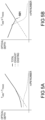
- Figures 5A and 5B are charts adapted from B. Karcher and F. Yu, "Role of aircraft soot emissions in contrail formation", Geophysical Research Letters, vol. 36, no. 1, 2009 , which is incorporated herein by reference.
- the charts show the dependence of contrail optical depth on nvPM number at a fixed ambient relative humidity over water.
- the contributing factors to the contrails' optical depth (solid) are ice particles formed from deposition on exhaust soot (dashed), and ice particles formed from emitted and/or existing ambient liquid particles (dot-dashed).
- Figure 5A shows the relationship for ambient temperatures above some transition temperature (T AMB > T TRANS )
- Figure 5B shows the relationship for ambient temperatures at or below the transition temperature (T AMB ⁇ T TRANS )
- nvPM number As shown in Figure 5A , with ambient temperatures greater than the transition temperature, and at higher nvPM numbers, exhausted non-volatile particulate matter is largely determinative of the contrail's optical depth. At lower nvPM numbers, emitted and/or existing ambient liquid particles which freeze in the exhaust plume begin to dominate the contribution to overall optical depth. As can be seen, above the transition temperature, the relationship between nvPM number and optical depth is one which is monotonically increasing.
- an aero engine may be producing few soot emissions, it may still be forming a contrail having greater optical depth than an engine producing substantially greater soot emissions. Depending upon other factors, this could have a more detrimental climate impact.
- the transition temperature T TRANS is, when considering a reduction in temperature, the temperature at which the relationship ceases to be monotonically increasing, with a stationary point appearing at the transition value 501.
- transition temperature for any particular ambient relative humidity over water may be determined in accordance with the modelling approach set out in B. Karcher, U. Burkhardt, A. Bier, L. Bock and I. Ford, "The microphysical pathway to contrail formation", Journal of Geophysical Research: Atmospheres, vol. 120, no. 15, pp. 7893-7927, 2015 , which is incorporated herein by reference.
- control of the variable geometry combustion system by way of a variable geometry airflow arrangement may be used to effect changes in nvPM number.
- This characteristic in conjunction with the relationships between nvPM number and optical depth described with reference to Figures 5A and 5B , allows the electronic engine controller 212 to effect changes in optical depth.
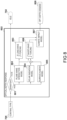
- FIG. 6 A block diagram is shown in Figure 6 that illustrates sensor inputs, memory registers and processing modules in the electronic engine controller 212 to control the variable geometry airflow arrangement 303 in accordance with a target index of soot emissions. As described previously, in the present embodiment this is performed in dependence upon atmospheric conditions.
- the electronic engine controller 212 comprises an atmospheric condition analysis module 601, an optical depth response module 602, and an airflow control module 603.
- the atmospheric condition analysis module 601 will be described in further detail with reference to Figure 7 .
- the optical depth response module 602 will be described in further detail with reference to Figures 8 and 9 .
- the airflow control module 603 will be described in further detail with reference to Figure 10 .
- the modules 601, 602, and 603 operate together to form an appropriate contrail optical depth response to an atmospheric condition in the form of variable geometry setting for implementation by the variable geometry airflow arrangement 303.
- modules 601, 602 and 603 are described as software running on the electronic engine controller 212, they may be implemented as software running on separate control units or even implemented in dedicated hardware. It will also be appreciated that some or all of the processing steps described herein for the modules 601, 602 and 603 could be carried out at a location which is physically remote from the aircraft, making use of suitable datalinks to transmit data from the aircraft to the processing location and vice versa.
- each module 601, 602, and 603 is configured such that it has access to a plurality of registers storing various sensor outputs and/or downloaded data.
- An optical sensor 611 is configured to produce image data 621 of the exhaust plume region of the engine 105. This facilitates analysis of the optical depth of a contrail being generated by the engine 105 during flight, and thus closed loop control of optical depth. Additionally or alternatively, other types of sensors such as lidar or radar may be used to generate data suitable for analysis of the contrail optical depth.
- a temperature sensor 612 for example, an outside air temperature probe or similar
- a pressure sensor 613 for example, an aneroid barometer forming part of a pitot-static arrangement or similar
- a humidity sensor 614 for example, a hygrometer or similar
- a positioning system 615 for example Global Positioning System, Galileo, etc. provides geolocation data 625.
- a data downlink 616 (for example satellite communication) facilitates acquisition of satellite imagery 626A and weather forecasts 626B to allow identification of regions conducive to contrail formation and/or contrail persistence.
- the output of a power lever angle sensor 617 in the cockpit of the aircraft 102 is converted into total fuel flow (W F ) demand 627 by, for example, a surrogate engine model in the electronic engine controller 212.
- the electronic engine controller 212 is configured to determine a corresponding total air mass flow quantity entering the combustor 206 (W 30 ) to permit calculation of fuel-air ratio, etc.
- the design of such control loops will be familiar to those skilled in the art.
- sensors and registers may be selected for implementation.
- optical sensors may be deployed and be the sole means of detection of contrail formation.
- temperature, pressure and humidity instruments may be selected for use in detection of conditions which indicate that contrails will form, and so on.
- the atmospheric condition analysis module 601 is shown in detail in Figure 7 .
- Input data obtained from some or all of the registers 621-627 is obtained by a contrail formation model 701.
- the contrail formation model 701 is configured to determine whether or not contrail formation is likely under current ambient conditions and engine operating point, irrespective of subsequent persistence.
- the contrail formation model 701 uses the real- or near real-time atmospheric condition data measured by the sensors.
- the measurement of ambient humidity 624 by the humidity sensor 614 may be used, or the image data 621 produced by the optical sensor 611.
- the contrail formation model 701 utilises the satellite imagery 626A and/or the weather forecasts 626B to determine whether atmospheric conditions are such that contrails will form.
- the satellite imagery 626A is used in conjunction with the geolocation data 625 and an altitude reading derived from the ambient pressure 623 to confirm whether or not other aircraft in the vicinity have caused contrails or not.
- the weather forecasts 626B are coupled to the Schmidt-Appleman criterion approach described above.
- the contrail formation model 701 determines that no contrail will form given current atmospheric conditions, then no action is taken and the atmospheric condition analysis module 601 proceeds to an idle process 702 where it waits until new input data are available.
- contrail formation model 701 determines that a contrail will form, then control proceeds to a contrail type classifier 703 which is configured to determine, given ambient conditions, whether the contrail will persist or not. This may be achieved by assessing the ambient relative humidity with respect to ice: if the ambient air is supersaturated with respect to ice, then the contrail will persist.
- the output of the contrail type classifier 703 is the determined contrail type 704, and is provided to the optical depth response module 602.
- the optical depth response module 602 receives the determined contrail type 704 from the atmospheric condition analysis module 601, and proceeds to ask a question at a decision block 801 as to whether the contrail will be persistent, or not.
- a plume-wake interaction model 802 is provided which assesses the effect of the wake of the aircraft 102 on the exhaust plume of the engine 105. This model will be described in further detail with reference to Figure 9 .
- the model 802 outputs a set of predictions of the time-varying properties of a plurality of contrails, each caused by exhaust plumes having different nvPM numbers.
- the output of model 802 is provided to a long-wave forcing model 803, which is configured to determine the time-integrated radiative forcing per unit length of each contrail due to long-wave (i.e. warming) effects over their expected lifetimes.
- a solar radiation model 804 and a surface albedo model 805 are executed and their outputs combined.
- the solar radiation model 804 is configured to determine the strength and orientation of incoming sunlight over the expected lifetime of the contrail in the post-vortex regime.
- the surface albedo model 805 is configured to determine the albedo of surfaces (including other clouds) which would receive incoming sunlight in the absence of a contrail formed by the aircraft.
- models 804 and 805 utilise the satellite imagery 626A and weather forecast data 626B to perform this assessment.
- model 804 and 805 are supplied, along with the output of model 802, to a short-wave forcing model 806 which is configured to determine the time-integrated radiative forcing due to short-wave (i.e. cooling) effects over the expected lifetime of the predicted set of contrails generated by the model 802.
- the outputs of the long-wave forcing model 803 and the short-wave forcing model 806 are supplied to a climate impact model 807 which determines the optimal optical depth to achieve the best balance between the magnitudes of the modelled short-wave cooling and long-wave warming effects.
- model 807 determines that the optical depth of the condensation trail should be increased or decreased on the basis of a time-integrated effect of a persistent contrail over its lifespan given a current atmospheric condition and a predicted future atmospheric condition.
- the output of model 807 is an optical depth demand 808, which is supplied to the airflow control module 603.
- the optical depth demand 808 is a target optical depth for the contrail.
- the target index of soot emissions is derived by identifying a condition to the effect that an optical depth of a condensation trail produced by the engine should be either reduced or increased. In response to identifying that the optical depth should be reduced, the target index of soot emissions is updated so as to reduce ice particle formation. In response to identifying that the optical depth should be increased, the target index of soot emissions is updated so as to increase ice particle formation.
- the climate impact model 807 is configured to consider short-wave cooling to be a desirable effect, and long-wave warming to be an undesirable effect, and thus tends to produce an optical depth demand 808 which reduces the net warming impact of the contrail.
- the idle process 702 is invoked until new input data are available.
- measures may still be taken to alter the optical depth, possibly adopting a similar approach to that for persistent contrails.
- the plume-wake interaction model 802 is shown in more detail in Figure 9 .
- the model 802 obtains input data pertaining to, in particular, the operating point 901 of the engine 105 (for example intake temperature and pressure, power lever angle setting, overall fuel flow rate, etc.) and the ambient conditions 902 at the current location of the aircraft 102 (for example ambient temperature 622, ambient pressure 623, ambient humidity 624, etc.).
- the operating point 901 of the engine 105 for example intake temperature and pressure, power lever angle setting, overall fuel flow rate, etc.
- the ambient conditions 902 at the current location of the aircraft 102 for example ambient temperature 622, ambient pressure 623, ambient humidity 624, etc.
- an ice crystal distribution model 903 which is configured to determine, for each of a plurality of possible nvPM numbers, the initial particle size distribution of ice particles formed in the exhaust plume of the engine 105. In the present embodiment, this is performed on the basis of factors including ambient temperature 622, ambient pressure 623, ambient humidity 624, the mass of water vapour emitted by the engine per unit distance of travel, and the efficiency of the engine 105.
- the ice crystal distribution model 903 is configured to determine the mass of water vapour using the data pertaining to engine operating point 901, i.e. power lever setting, fuel flow rate, fuel properties, calculated airspeed, etc.
- the ice crystal distributions are supplied to an ice crystal entrainment model 904, which is configured to determine the extent to which particles in the engine exhaust become captured by wingtip vortices of the aircraft 102.
- the ice crystal entrainment model 904 is configured to determine the particle size distribution of ice particles initially captured within the wingtip vortex core, given an initial particle size distribution of a newly formed contrail, in dependence upon the location of the corresponding engine relative to the wingtip. It is further configured to determine the number or ratio of ice particles which remain after the adiabatic heating experienced within the wingtip vortex core during the lifetime of the wingtip vortex. The remaining ice particles also include those ice particles which were detrained from the vortex prior to its breakup.
- a wingtip vortex lifetime model 905 is configured to determine the lifetime of a wingtip vortex in dependence upon such factors as the strength of ambient turbulence, the rate of change of ambient temperature with altitude, and/or the instantaneous aircraft weight (e.g. taking account of the amount of fuel burned so far during the flight).
- a vortex descent velocity model 906 is configured to determine the downward velocity of a wingtip vortex, in dependence upon factors including the instantaneous aircraft weight, and aircraft configuration.
- a vortex temperature rise model 907 is configured to determine the temperature change likely to be experienced within the vortex core as a result of the determined change in altitude during its descent and/or the speed of its descent.
- the output of ice crystal entrainment model 904 is then supplied to a wind shear model 908 which predicts the degree of horizontal spreading of the contrail over its expected lifetime. This prediction is performed using the vertical extent of the post-vortex contrail, and current and future weather conditions obtained from the weather forecasts 626B. This is performed to account for the contrail's short-and long-wave effects.
- the output from the plume-wake interaction model 802 is thus a set of contrail lifecycle data 909 for a plurality of nvPM numbers.
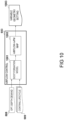
- the airflow control module 603 is shown in greater detail in Figure 10 .
- Model 1001 is configured to determine a target nvPM number under the current ambient atmospheric conditions, in particular the ambient temperature, which will meet the optical depth demand 808. In the present embodiment, this is achieved by use of the contrail lifecycle data 909.
- the model 1001 may implement a microphysical simulation to establish the target nvPM number.
- This target nvPM number is then used as a set point for evaluating appropriate values for the variable geometry airflow arrangement 303.
- a map 1002 is used, allowing an efficient lookup of the appropriate settings for the variable geometry airflow arrangement 303 to produce the requisite airflow settings for either the fuel injector 302 or the quench ports to achieve a target nvPM number, given an overall airflow rate into the combustor 206 and overall fuel flow rate W F .
- a surrogate model may be implemented to model the combustion process based on real time parameters.
- the airflow control module 603 controls the variable geometry airflow arrangement 303 by taking these different regimes into account.
- the airflow control module 603 compares a newly-received optical depth demand 808 with the current value thereof. Thus the airflow control module 603 determines whether the optical depth of a contrail should be reduced, or increased.
- the airflow control module 603 evaluates a variable geometry setting 1003 that varies nvPM number (and thus soot production) to minimise ice particle formation.
- soot formation model 1001 and map 1002 effectively compares a measurement of ambient temperature to the transition temperature. Then, if the ambient temperature is greater than the transition temperature, a variable geometry setting 1003 is determined that, if possible, decreases soot production to achieve the target optical depth. It will be appreciated that if the lowest possible level of soot production has already been reached, then the variable geometry setting 1003 will remain the same.
- variable geometry setting 1003 is determined that either decreases or increases soot production. This is performed in dependence upon whether the current variable geometry setting 1003, and hence nvPM number, is above or below the transition value 501.
- the minimum optical depth that may be achieved is that obtained when the variable geometry setting 1003 corresponds to the transition value 501.
- the airflow control module 603 evaluates a variable geometry setting 1003 that varies nvPM number (and thus soot production) to increase ice particle formation.
- the effect of the airflow control module's configuration is then to obtain a measurement of ambient temperature.
- variable geometry setting 1003 is determined that increases soot production to achieve the target optical depth.
- variable geometry setting 1003 is determined that increases the index of soot emissions.
- the decision as to whether to increase or decrease nvPM number to increase optical depth may be influenced by which operational change is associated with, for example, the lowest fuel consumption.
- other parameters may influence this decision, such as emissions of unburnt hydrocarbons, oxides of nitrogen, or even impact on life-limited parts, etc.
- Example configurations of the combustor 206 are shown in Figures 11A, 11B and 11C .
- the combustor 206 is configured as an RQL combustor as illustrated in Figure 11A .
- fuel F is injected by the fuel injectors 302 into a rich-burn zone 1101, in which the fuel-air ratio is fuel rich.
- quench air Q is admitted to a quick-quench zone 1102 to quickly reduce the flame temperature.
- the combustor 206 comprises two rows of axially-separated quench ports 1103. Amongst other things, this reduces formation of oxides of nitrogen. It also causes continued combustion to occur under lean conditions in a lean-burn zone 1104.
- the net quantity of soot produced by the combustor 206 may be influenced by the fuel-air ratio in the rich-burn zone 1101, which governs the total quantity of soot produced, and the amount of quench air Q admitted to the quick-quench zone 1102, which governs the total quantity of soot burnt off in the lean burn zone 1104.
- FIG. 11B An alternative combustor 206' is shown in Figure 11B , in which only one row of quench ports 1103 is provided.
- FIG. 11C Another alternative combustor 206" is shown in Figure 11C , in which one row of quench ports 1103 is provided on both the inner and outer walls of the combustor 206". It will be appreciated that the principles disclosed herein may be applied to a variety of RQL combustor configurations.
- FIG. 12 A section through the combustor 206 is shown in Figure 12 .
- the combustor 206 is mounted within a cavity 1201 formed by an inner air casing 1202 and outer air casing 1203.
- the high-pressure compressor 205 delivers pressurised core airflow C to the cavity 1201 via a diffuser 1204.
- a quantity of the air enters the combustor 206 as combustion air D through the fuel injector 302 and/or mixing ports at the entrance to the combustor 206 into the rich-burn zone 1101.
- the remaining air flows around the combustor 206 as cooling air E, a quantity of which is admitted into combustor 206 as quench air Q into the quick-quench zone 1102 via the quench ports 1103.
- the remaining cooling air E may be directed to cool the liner of the combustor 206 and/or as dilution air prior to entering the high-pressure turbine 207, etc.
- the combustor 206 is a variable geometry combustor and comprises a variable geometry airflow arrangement 303 to vary the airflow through the fuel injectors 302 and/or the quench ports 1103. This is because, if airflow is varied through the fuel injectors 302, there is an opposing change in airflow through the quench ports 1103. In this way, the fuel-air ratio for the fuel injectors 302 and the amount of quench air Q may be varied by the electronic engine controller 212 to achieve a target index of soot emissions.
- nvPM number will be met by an increase in airflow through the quench ports 1103 relative to airflow through the fuel injectors 302.
- the fuel-air ratio in the rich-burn zone 1101 will be increased, leading to a locally richer mixture and hence an increase in soot formation.
- the amount of quench air Q will be increased, thereby decreasing temperature in the lean-burn zone 1104, and in turn decreasing soot burn-off.
- the combination of increased soot formation and decreased soot burn-off leads to a net increase in nvPM number in the products of combustion.
- the quench ports 1103 are variable geometry quench ports.
- the configuration of the variable geometry quench ports will be described further with reference to Figures 13A, 13B and 13C .
- the fuel injectors 302 are variable geometry fuel injectors. The configuration of such variable geometry fuel injectors will be described further with reference to Figures 15A and 15B .
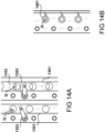
- variable geometry quench ports 1103 are shown in plan view in Figures 13A, 13B and 13C .
- the area of the quench ports 1103 are varied by an annular strip 1301 having apertures 1302 corresponding to the quench ports 1103. Circumferential movement of the strip 1301 and hence alignment of the apertures 1302 and quench ports 1103 either opens them admitting a full quantity of quench air Q ( Figure 13A ), partially closes them admitting less quench air Q ( Figure 13B ), and possibly even fully closes them admitting no quench air Q ( Figure 13C ). It will be appreciated that in turn this also varies the airflow through the fuel injector 302 as described previously.
- the movement of the strip 1301 is effected by a rotary actuator 1303.
- the rotary actuator 1303 is rotated by a control rod (not shown), in turn rotated by hydraulic actuation (not shown).
- a control rod not shown
- hydraulic actuation not shown
- variable geometry quench ports 1103 may be applied to combustor 206' or combustor 206".
- combustor 206 comprises two rows of axially-separated quench ports 1103. As shown in Figure 14A , it is possible for two sets of strips 1301 and actuators 1303 to be provided so as to allow modulation of quench air Q through each row independently.
- the electronic engine controller 212 is configured to control the strips 1301 such that airflow is varied through one row of quench ports 1103 in an opposite sense to variation of airflow through the other row of quench ports 1103. This opposing variation may be inversely proportional or nonlinear depending upon the implementation.
- the electronic engine controller 212 is configured to control the strips 1301 to maintain a constant total airflow through the quench ports 1103 for a given airflow C admitted to the combustor 206.
- variable geometry quench ports 1103 An alternative embodiment for the variable geometry quench ports 1103 is shown in Figure 14B .
- the area is varied by way of a variable area iris 1401.
- the same control strategies may be applied, and indeed in such an arrangement, the geometry of each quench port could be varied independently.
- the fuel injectors 302 may be configured as variable geometry fuel injectors and hence comprise the variable geometry airflow arrangement 303.
- a section of one of the fuel injectors 302 is shown in Figures 15A and 15B .
- the fuel injector 302 comprises an inner duct 1501 for admitting a portion of combustion air D INNER and delivering it to the combustor 206. Close to the outlet of the inner duct 1501, fuel F is delivered into the airflow via a fuel circuit 1502. Further airflow D OUTER is delivered into the combustor 206 via an outer duct 1503 concentric with the inner duct 1501.
- the fuel injector 302 comprises a translatable ramp 1504 to provide the variable geometry function, which ramp is configured to move axially to vary the inlet area of the outer duct 1503 - note the difference in inlet area between Figure 14A and Figure 14B .
- the translatable ramp 1504 is translatable by way of a lever arm driven by a shaft, in turn driven by a unison ring arrangement (none shown). Such arrangements are described in United States Patent No 5,664,412 , which is assigned to the present applicant, and incorporated herein by reference.
- Other actuation systems may be utilised, for example other mechanical arrangements, or pneumatic or hydraulic pistons, for example.
- Other mechanisms may be employed, for example a variable area inlet to inner duct 1501.
- the ramp 1504 moves axially in accordance with the current variable geometry setting to vary the amount of airflow D OUTER , and hence the total airflow through the fuel injector 302. As a consequence the amount of quench air Q is therefore also varied as described previously.
- the system configuration disclosed herein may also lend itself for use in controlling nvPM parameters during different phases of flight, for example in the landing and take-off cycles.
- the target index of soot emissions may be derived on the basis of visibility limits, local air quality limits, etc.
Landscapes
- Engineering & Computer Science (AREA)
- Chemical & Material Sciences (AREA)
- Combustion & Propulsion (AREA)
- Mechanical Engineering (AREA)
- General Engineering & Computer Science (AREA)
- Manufacture, Treatment Of Glass Fibers (AREA)
- Physics & Mathematics (AREA)
- Fluid Mechanics (AREA)
- Combined Controls Of Internal Combustion Engines (AREA)
Applications Claiming Priority (1)
| Application Number | Priority Date | Filing Date | Title |
|---|---|---|---|
| GBGB2112642.0A GB202112642D0 (en) | 2021-09-06 | 2021-09-06 | Controlling soot |
Publications (2)
| Publication Number | Publication Date |
|---|---|
| EP4144973A1 true EP4144973A1 (de) | 2023-03-08 |
| EP4144973B1 EP4144973B1 (de) | 2024-07-03 |
Family
ID=78076889
Family Applications (1)
| Application Number | Title | Priority Date | Filing Date |
|---|---|---|---|
| EP22191701.6A Active EP4144973B1 (de) | 2021-09-06 | 2022-08-23 | Kontrolle von russ |
Country Status (3)
| Country | Link |
|---|---|
| US (1) | US12241629B2 (de) |
| EP (1) | EP4144973B1 (de) |
| GB (1) | GB202112642D0 (de) |
Families Citing this family (7)
| Publication number | Priority date | Publication date | Assignee | Title |
|---|---|---|---|---|
| US20250216078A1 (en) * | 2023-12-29 | 2025-07-03 | Rtx Corporation | Separating airflows within a turbine engine |
| US12345165B1 (en) | 2024-02-29 | 2025-07-01 | General Electric Company | Gas turbine engine having multiple steam turbines |
| GB202408246D0 (en) * | 2024-06-10 | 2024-07-24 | Rolls Royce Plc | fuel spray nozzles |
| GB202408245D0 (en) * | 2024-06-10 | 2024-07-24 | Rolls Royce Plc | an aircraft |
| GB202408224D0 (en) * | 2024-06-10 | 2024-07-24 | Rolls Royce Plc | Aircraft fuel delivery |
| GB202408228D0 (en) | 2024-06-10 | 2024-07-24 | Rolls Royce Plc | gas turbine performance |
| GB202408243D0 (en) | 2024-06-10 | 2024-07-24 | Rolls Royce Plc | Available thrust |
Citations (4)
| Publication number | Priority date | Publication date | Assignee | Title |
|---|---|---|---|---|
| US4412414A (en) * | 1980-09-22 | 1983-11-01 | General Motors Corporation | Heavy fuel combustor |
| US5664412A (en) | 1995-03-25 | 1997-09-09 | Rolls-Royce Plc | Variable geometry air-fuel injector |
| US20110300493A1 (en) * | 2008-10-14 | 2011-12-08 | Franklin F Mittricker | Methods and Systems For Controlling The Products of Combustion |
| EP2677138A2 (de) * | 2012-06-22 | 2013-12-25 | Rolls-Royce plc | Kraftstoffsystem |
Family Cites Families (29)
| Publication number | Priority date | Publication date | Assignee | Title |
|---|---|---|---|---|
| US2780055A (en) | 1950-11-18 | 1957-02-05 | United Aircraft Corp | Igniter control for engines |
| US3423930A (en) | 1967-06-19 | 1969-01-28 | Bendix Corp | Fuel control apparatus including put-and-take fuel bypass valve means for withdrawing controlled percentage of metered fuel |
| US3952501A (en) * | 1971-04-15 | 1976-04-27 | United Aircraft Of Canada Limited | Gas turbine control |
| FR2391359A2 (fr) * | 1977-05-18 | 1978-12-15 | Snecma | Chambre de combustion pour turbomachines |
| FR2357738A1 (fr) * | 1976-07-07 | 1978-02-03 | Snecma | Chambre de combustion pour turbomachines |
| US4255927A (en) * | 1978-06-29 | 1981-03-17 | General Electric Company | Combustion control system |
| GB2085146B (en) * | 1980-10-01 | 1985-06-12 | Gen Electric | Flow modifying device |
| GB2086031B (en) * | 1980-10-22 | 1984-04-18 | Gen Motors Corp | Gas turbine combustion system |
| FR2572463B1 (fr) * | 1984-10-30 | 1989-01-20 | Snecma | Systeme d'injection a geometrie variable. |
| JP2644745B2 (ja) | 1987-03-06 | 1997-08-25 | 株式会社日立製作所 | ガスタービン用燃焼器 |
| DE3819898A1 (de) | 1988-06-11 | 1989-12-14 | Daimler Benz Ag | Brennkammer fuer eine thermische stroemungsmaschine |
| US5285628A (en) * | 1990-01-18 | 1994-02-15 | Donlee Technologies, Inc. | Method of combustion and combustion apparatus to minimize Nox and CO emissions from a gas turbine |
| US5207064A (en) | 1990-11-21 | 1993-05-04 | General Electric Company | Staged, mixed combustor assembly having low emissions |
| DE4110507C2 (de) | 1991-03-30 | 1994-04-07 | Mtu Muenchen Gmbh | Brenner für Gasturbinentriebwerke mit mindestens einer für die Zufuhr von Verbrennungsluft lastabhängig regulierbaren Dralleinrichtung |
| FR2683891B1 (fr) * | 1991-11-20 | 1995-03-24 | Snecma | Turbomachine comportant un dispositif pour diminuer l'emission d'oxydes d'azote. |
| US5239818A (en) * | 1992-03-30 | 1993-08-31 | General Electric Company | Dilution pole combustor and method |
| US5636510A (en) | 1994-05-25 | 1997-06-10 | Westinghouse Electric Corporation | Gas turbine topping combustor |
| WO1996030637A1 (en) * | 1995-03-24 | 1996-10-03 | Ultimate Power Engineering Group, Inc. | High vanadium content fuel combustor and system |
| US5673552A (en) | 1996-03-29 | 1997-10-07 | Solar Turbines Incorporated | Fuel injection nozzle |
| US6199367B1 (en) | 1996-04-26 | 2001-03-13 | General Electric Company | Air modulated carburetor with axially moveable fuel injector tip and swirler assembly responsive to fuel pressure |
| JP3448190B2 (ja) | 1997-08-29 | 2003-09-16 | 三菱重工業株式会社 | ガスタービンの燃焼器 |
| FR2779807B1 (fr) | 1998-06-11 | 2000-07-13 | Inst Francais Du Petrole | Chambre de combustion de turbine a gaz a geometrie variable |
| US6826913B2 (en) * | 2002-10-31 | 2004-12-07 | Honeywell International Inc. | Airflow modulation technique for low emissions combustors |
| GB201317175D0 (en) | 2013-09-27 | 2013-11-06 | Rolls Royce Plc | An apparatus and a method of controlling the supply of fuel to a combustion chamber |
| GB201405894D0 (en) | 2014-04-02 | 2014-05-14 | Rolls Royce Plc | Aircraft vapour trail control system |
| GB201506473D0 (en) * | 2015-04-16 | 2015-06-03 | Rolls Royce Plc | Aircraft propulsion system |
| US10480403B2 (en) | 2016-02-22 | 2019-11-19 | King Fahd University Of Petroleum And Minerals | Combustor with adjustable swirler and a combustion system |
| US10954859B2 (en) | 2017-07-25 | 2021-03-23 | Raytheon Technologies Corporation | Low emissions combustor assembly for gas turbine engine |
| GB201808070D0 (en) | 2018-05-18 | 2018-07-04 | Rolls Royce Plc | Burner |
-
2021
- 2021-09-06 GB GBGB2112642.0A patent/GB202112642D0/en not_active Ceased
-
2022
- 2022-08-23 EP EP22191701.6A patent/EP4144973B1/de active Active
- 2022-08-26 US US17/896,442 patent/US12241629B2/en active Active
Patent Citations (4)
| Publication number | Priority date | Publication date | Assignee | Title |
|---|---|---|---|---|
| US4412414A (en) * | 1980-09-22 | 1983-11-01 | General Motors Corporation | Heavy fuel combustor |
| US5664412A (en) | 1995-03-25 | 1997-09-09 | Rolls-Royce Plc | Variable geometry air-fuel injector |
| US20110300493A1 (en) * | 2008-10-14 | 2011-12-08 | Franklin F Mittricker | Methods and Systems For Controlling The Products of Combustion |
| EP2677138A2 (de) * | 2012-06-22 | 2013-12-25 | Rolls-Royce plc | Kraftstoffsystem |
Non-Patent Citations (3)
| Title |
|---|
| B. KARCHERF. YU: "Role of aircraft soot emissions in contrail formation", GEOPHYSICAL RESEARCH LETTERS, vol. 36, no. 1, 2009, XP071426772, DOI: 10.1029/2008GL036649 |
| B. KARCHERU. BURKHARDTA. BIERL. BOCKI. FORD: "The microphysical pathway to contrail formation", JOURNAL OF GEOPHYSICAL RESEARCH: ATMOSPHERES, vol. 120, no. 15, 2015, pages 7893 - 7927 |
| LIU YIZE ET AL: "Review of modern low emissions combustion technologies for aero gas turbine engines", PROGRESS IN AEROSPACE SCIENCES, vol. 94, 1 October 2017 (2017-10-01), GB, pages 12 - 45, XP055923018, ISSN: 0376-0421, DOI: 10.1016/j.paerosci.2017.08.001 * |
Also Published As
| Publication number | Publication date |
|---|---|
| GB202112642D0 (en) | 2021-10-20 |
| US12241629B2 (en) | 2025-03-04 |
| US20230072621A1 (en) | 2023-03-09 |
| EP4144973B1 (de) | 2024-07-03 |
Similar Documents
| Publication | Publication Date | Title |
|---|---|---|
| US11821373B2 (en) | Staged combustion | |
| EP4144973B1 (de) | Kontrolle von russ | |
| US11732659B2 (en) | Controlling soot | |
| EP2930330B1 (de) | Gasturbinenmotor | |
| Spang III et al. | Control of jet engines | |
| US10259590B2 (en) | Aircraft propulsion system | |
| EP3875740B1 (de) | Bereitstellung von kraftstoff | |
| EP3054125B1 (de) | Gasturbinenmotor mit variabler geometrie zur verwendung bei schlechtem wetter | |
| US11041446B2 (en) | Gas turbine engine fuel additive control system | |
| US20240068414A1 (en) | Method of contrail mitigation and aircraft having contrail mitigation functionality | |
| CN108168900B (zh) | 满足无人机用发动机宽包线范围推力需求的控制方法 | |
| Vera-Morales et al. | Modeling performance and emissions from aircraft in the aviation integrated modelling project | |
| US20200391873A1 (en) | System and method for operating a multi-engine rotorcraft for ice accretion shedding | |
| Burcham Jr et al. | Flight evaluation of a digital electronic engine control in an F-15 airplane | |
| Myers et al. | Preliminary flight test results of the F100 EMD engine in an F-15 airplane | |
| Balicki et al. | Aviation: environmental threats | |
| RU2493051C2 (ru) | Способ управления турбовинтовой силовой установкой самолета | |
| Vera-Morales et al. | Modelling performance and emissions from aircraft for the aviation integrated modelling project | |
| RU2620737C1 (ru) | Способ регулирования авиационного турбореактивного двигателя | |
| Calder | Olympus 593 powerplant in concorde | |
| Thompson | Controller and Engine Simulation Implementation | |
| CA3079884A1 (en) | No title specified | |
| Merkisz et al. | EXHAUST EMISSIONS MEASURMENTS FROM A SMALL AIRPLANE | |
| Yunusov et al. | Statistical Representation of Turbofan Operational Characteristics by Thrust Parameter | |
| BURCHAM, JR et al. | Flight evaluation results for a digital electronic engine control inan F-15 airplane |
Legal Events
| Date | Code | Title | Description |
|---|---|---|---|
| PUAI | Public reference made under article 153(3) epc to a published international application that has entered the european phase |
Free format text: ORIGINAL CODE: 0009012 |
|
| STAA | Information on the status of an ep patent application or granted ep patent |
Free format text: STATUS: THE APPLICATION HAS BEEN PUBLISHED |
|
| AK | Designated contracting states |
Kind code of ref document: A1 Designated state(s): AL AT BE BG CH CY CZ DE DK EE ES FI FR GB GR HR HU IE IS IT LI LT LU LV MC MK MT NL NO PL PT RO RS SE SI SK SM TR |
|
| STAA | Information on the status of an ep patent application or granted ep patent |
Free format text: STATUS: REQUEST FOR EXAMINATION WAS MADE |
|
| 17P | Request for examination filed |
Effective date: 20230904 |
|
| RBV | Designated contracting states (corrected) |
Designated state(s): AL AT BE BG CH CY CZ DE DK EE ES FI FR GB GR HR HU IE IS IT LI LT LU LV MC MK MT NL NO PL PT RO RS SE SI SK SM TR |
|
| GRAP | Despatch of communication of intention to grant a patent |
Free format text: ORIGINAL CODE: EPIDOSNIGR1 |
|
| STAA | Information on the status of an ep patent application or granted ep patent |
Free format text: STATUS: GRANT OF PATENT IS INTENDED |
|
| RIC1 | Information provided on ipc code assigned before grant |
Ipc: F23R 3/26 20060101ALI20240314BHEP Ipc: F23R 3/34 20060101ALI20240314BHEP Ipc: F02C 9/48 20060101ALI20240314BHEP Ipc: F02C 9/28 20060101ALI20240314BHEP Ipc: F02C 7/228 20060101AFI20240314BHEP |
|
| INTG | Intention to grant announced |
Effective date: 20240416 |
|
| GRAS | Grant fee paid |
Free format text: ORIGINAL CODE: EPIDOSNIGR3 |
|
| P01 | Opt-out of the competence of the unified patent court (upc) registered |
Effective date: 20240424 |
|
| GRAA | (expected) grant |
Free format text: ORIGINAL CODE: 0009210 |
|
| STAA | Information on the status of an ep patent application or granted ep patent |
Free format text: STATUS: THE PATENT HAS BEEN GRANTED |
|
| AK | Designated contracting states |
Kind code of ref document: B1 Designated state(s): AL AT BE BG CH CY CZ DE DK EE ES FI FR GB GR HR HU IE IS IT LI LT LU LV MC MK MT NL NO PL PT RO RS SE SI SK SM TR |
|
| REG | Reference to a national code |
Ref country code: CH Ref legal event code: EP |
|
| REG | Reference to a national code |
Ref country code: DE Ref legal event code: R096 Ref document number: 602022004291 Country of ref document: DE |
|
| REG | Reference to a national code |
Ref country code: LT Ref legal event code: MG9D |
|
| REG | Reference to a national code |
Ref country code: NL Ref legal event code: MP Effective date: 20240703 |
|
| PG25 | Lapsed in a contracting state [announced via postgrant information from national office to epo] |
Ref country code: PT Free format text: LAPSE BECAUSE OF FAILURE TO SUBMIT A TRANSLATION OF THE DESCRIPTION OR TO PAY THE FEE WITHIN THE PRESCRIBED TIME-LIMIT Effective date: 20241104 |
|
| REG | Reference to a national code |
Ref country code: AT Ref legal event code: MK05 Ref document number: 1700038 Country of ref document: AT Kind code of ref document: T Effective date: 20240703 |
|
| PG25 | Lapsed in a contracting state [announced via postgrant information from national office to epo] |
Ref country code: NL Free format text: LAPSE BECAUSE OF FAILURE TO SUBMIT A TRANSLATION OF THE DESCRIPTION OR TO PAY THE FEE WITHIN THE PRESCRIBED TIME-LIMIT Effective date: 20240703 |
|
| PG25 | Lapsed in a contracting state [announced via postgrant information from national office to epo] |
Ref country code: PT Free format text: LAPSE BECAUSE OF FAILURE TO SUBMIT A TRANSLATION OF THE DESCRIPTION OR TO PAY THE FEE WITHIN THE PRESCRIBED TIME-LIMIT Effective date: 20241104 Ref country code: NL Free format text: LAPSE BECAUSE OF FAILURE TO SUBMIT A TRANSLATION OF THE DESCRIPTION OR TO PAY THE FEE WITHIN THE PRESCRIBED TIME-LIMIT Effective date: 20240703 |
|
| PG25 | Lapsed in a contracting state [announced via postgrant information from national office to epo] |
Ref country code: NO Free format text: LAPSE BECAUSE OF FAILURE TO SUBMIT A TRANSLATION OF THE DESCRIPTION OR TO PAY THE FEE WITHIN THE PRESCRIBED TIME-LIMIT Effective date: 20241003 |
|
| PG25 | Lapsed in a contracting state [announced via postgrant information from national office to epo] |
Ref country code: FI Free format text: LAPSE BECAUSE OF FAILURE TO SUBMIT A TRANSLATION OF THE DESCRIPTION OR TO PAY THE FEE WITHIN THE PRESCRIBED TIME-LIMIT Effective date: 20240703 Ref country code: GR Free format text: LAPSE BECAUSE OF FAILURE TO SUBMIT A TRANSLATION OF THE DESCRIPTION OR TO PAY THE FEE WITHIN THE PRESCRIBED TIME-LIMIT Effective date: 20241004 Ref country code: PL Free format text: LAPSE BECAUSE OF FAILURE TO SUBMIT A TRANSLATION OF THE DESCRIPTION OR TO PAY THE FEE WITHIN THE PRESCRIBED TIME-LIMIT Effective date: 20240703 |
|
| PG25 | Lapsed in a contracting state [announced via postgrant information from national office to epo] |
Ref country code: BG Free format text: LAPSE BECAUSE OF FAILURE TO SUBMIT A TRANSLATION OF THE DESCRIPTION OR TO PAY THE FEE WITHIN THE PRESCRIBED TIME-LIMIT Effective date: 20240703 |
|
| PG25 | Lapsed in a contracting state [announced via postgrant information from national office to epo] |
Ref country code: LV Free format text: LAPSE BECAUSE OF FAILURE TO SUBMIT A TRANSLATION OF THE DESCRIPTION OR TO PAY THE FEE WITHIN THE PRESCRIBED TIME-LIMIT Effective date: 20240703 |
|
| PG25 | Lapsed in a contracting state [announced via postgrant information from national office to epo] |
Ref country code: IS Free format text: LAPSE BECAUSE OF FAILURE TO SUBMIT A TRANSLATION OF THE DESCRIPTION OR TO PAY THE FEE WITHIN THE PRESCRIBED TIME-LIMIT Effective date: 20241103 Ref country code: AT Free format text: LAPSE BECAUSE OF FAILURE TO SUBMIT A TRANSLATION OF THE DESCRIPTION OR TO PAY THE FEE WITHIN THE PRESCRIBED TIME-LIMIT Effective date: 20240703 |
|
| PG25 | Lapsed in a contracting state [announced via postgrant information from national office to epo] |
Ref country code: HR Free format text: LAPSE BECAUSE OF FAILURE TO SUBMIT A TRANSLATION OF THE DESCRIPTION OR TO PAY THE FEE WITHIN THE PRESCRIBED TIME-LIMIT Effective date: 20240703 Ref country code: CZ Free format text: LAPSE BECAUSE OF FAILURE TO SUBMIT A TRANSLATION OF THE DESCRIPTION OR TO PAY THE FEE WITHIN THE PRESCRIBED TIME-LIMIT Effective date: 20240703 |
|
| PG25 | Lapsed in a contracting state [announced via postgrant information from national office to epo] |
Ref country code: RS Free format text: LAPSE BECAUSE OF FAILURE TO SUBMIT A TRANSLATION OF THE DESCRIPTION OR TO PAY THE FEE WITHIN THE PRESCRIBED TIME-LIMIT Effective date: 20241003 Ref country code: ES Free format text: LAPSE BECAUSE OF FAILURE TO SUBMIT A TRANSLATION OF THE DESCRIPTION OR TO PAY THE FEE WITHIN THE PRESCRIBED TIME-LIMIT Effective date: 20240703 |
|
| PG25 | Lapsed in a contracting state [announced via postgrant information from national office to epo] |
Ref country code: RS Free format text: LAPSE BECAUSE OF FAILURE TO SUBMIT A TRANSLATION OF THE DESCRIPTION OR TO PAY THE FEE WITHIN THE PRESCRIBED TIME-LIMIT Effective date: 20241003 Ref country code: PL Free format text: LAPSE BECAUSE OF FAILURE TO SUBMIT A TRANSLATION OF THE DESCRIPTION OR TO PAY THE FEE WITHIN THE PRESCRIBED TIME-LIMIT Effective date: 20240703 Ref country code: NO Free format text: LAPSE BECAUSE OF FAILURE TO SUBMIT A TRANSLATION OF THE DESCRIPTION OR TO PAY THE FEE WITHIN THE PRESCRIBED TIME-LIMIT Effective date: 20241003 Ref country code: LV Free format text: LAPSE BECAUSE OF FAILURE TO SUBMIT A TRANSLATION OF THE DESCRIPTION OR TO PAY THE FEE WITHIN THE PRESCRIBED TIME-LIMIT Effective date: 20240703 Ref country code: IS Free format text: LAPSE BECAUSE OF FAILURE TO SUBMIT A TRANSLATION OF THE DESCRIPTION OR TO PAY THE FEE WITHIN THE PRESCRIBED TIME-LIMIT Effective date: 20241103 Ref country code: HR Free format text: LAPSE BECAUSE OF FAILURE TO SUBMIT A TRANSLATION OF THE DESCRIPTION OR TO PAY THE FEE WITHIN THE PRESCRIBED TIME-LIMIT Effective date: 20240703 Ref country code: GR Free format text: LAPSE BECAUSE OF FAILURE TO SUBMIT A TRANSLATION OF THE DESCRIPTION OR TO PAY THE FEE WITHIN THE PRESCRIBED TIME-LIMIT Effective date: 20241004 Ref country code: FI Free format text: LAPSE BECAUSE OF FAILURE TO SUBMIT A TRANSLATION OF THE DESCRIPTION OR TO PAY THE FEE WITHIN THE PRESCRIBED TIME-LIMIT Effective date: 20240703 Ref country code: ES Free format text: LAPSE BECAUSE OF FAILURE TO SUBMIT A TRANSLATION OF THE DESCRIPTION OR TO PAY THE FEE WITHIN THE PRESCRIBED TIME-LIMIT Effective date: 20240703 Ref country code: CZ Free format text: LAPSE BECAUSE OF FAILURE TO SUBMIT A TRANSLATION OF THE DESCRIPTION OR TO PAY THE FEE WITHIN THE PRESCRIBED TIME-LIMIT Effective date: 20240703 Ref country code: BG Free format text: LAPSE BECAUSE OF FAILURE TO SUBMIT A TRANSLATION OF THE DESCRIPTION OR TO PAY THE FEE WITHIN THE PRESCRIBED TIME-LIMIT Effective date: 20240703 Ref country code: AT Free format text: LAPSE BECAUSE OF FAILURE TO SUBMIT A TRANSLATION OF THE DESCRIPTION OR TO PAY THE FEE WITHIN THE PRESCRIBED TIME-LIMIT Effective date: 20240703 |
|
| REG | Reference to a national code |
Ref country code: DE Ref legal event code: R097 Ref document number: 602022004291 Country of ref document: DE |
|
| PG25 | Lapsed in a contracting state [announced via postgrant information from national office to epo] |
Ref country code: RO Free format text: LAPSE BECAUSE OF FAILURE TO SUBMIT A TRANSLATION OF THE DESCRIPTION OR TO PAY THE FEE WITHIN THE PRESCRIBED TIME-LIMIT Effective date: 20240703 Ref country code: SM Free format text: LAPSE BECAUSE OF FAILURE TO SUBMIT A TRANSLATION OF THE DESCRIPTION OR TO PAY THE FEE WITHIN THE PRESCRIBED TIME-LIMIT Effective date: 20240703 Ref country code: DK Free format text: LAPSE BECAUSE OF FAILURE TO SUBMIT A TRANSLATION OF THE DESCRIPTION OR TO PAY THE FEE WITHIN THE PRESCRIBED TIME-LIMIT Effective date: 20240703 |
|
| PG25 | Lapsed in a contracting state [announced via postgrant information from national office to epo] |
Ref country code: LU Free format text: LAPSE BECAUSE OF NON-PAYMENT OF DUE FEES Effective date: 20240823 |
|
| PG25 | Lapsed in a contracting state [announced via postgrant information from national office to epo] |
Ref country code: MC Free format text: LAPSE BECAUSE OF FAILURE TO SUBMIT A TRANSLATION OF THE DESCRIPTION OR TO PAY THE FEE WITHIN THE PRESCRIBED TIME-LIMIT Effective date: 20240703 Ref country code: EE Free format text: LAPSE BECAUSE OF FAILURE TO SUBMIT A TRANSLATION OF THE DESCRIPTION OR TO PAY THE FEE WITHIN THE PRESCRIBED TIME-LIMIT Effective date: 20240703 |
|
| PG25 | Lapsed in a contracting state [announced via postgrant information from national office to epo] |
Ref country code: IT Free format text: LAPSE BECAUSE OF FAILURE TO SUBMIT A TRANSLATION OF THE DESCRIPTION OR TO PAY THE FEE WITHIN THE PRESCRIBED TIME-LIMIT Effective date: 20240703 Ref country code: SK Free format text: LAPSE BECAUSE OF FAILURE TO SUBMIT A TRANSLATION OF THE DESCRIPTION OR TO PAY THE FEE WITHIN THE PRESCRIBED TIME-LIMIT Effective date: 20240703 |
|
| PLBE | No opposition filed within time limit |
Free format text: ORIGINAL CODE: 0009261 |
|
| STAA | Information on the status of an ep patent application or granted ep patent |
Free format text: STATUS: NO OPPOSITION FILED WITHIN TIME LIMIT |
|
| 26N | No opposition filed |
Effective date: 20250404 |
|
| REG | Reference to a national code |
Ref country code: BE Ref legal event code: MM Effective date: 20240831 |
|
| PG25 | Lapsed in a contracting state [announced via postgrant information from national office to epo] |
Ref country code: BE Free format text: LAPSE BECAUSE OF NON-PAYMENT OF DUE FEES Effective date: 20240831 |
|
| PG25 | Lapsed in a contracting state [announced via postgrant information from national office to epo] |
Ref country code: IE Free format text: LAPSE BECAUSE OF NON-PAYMENT OF DUE FEES Effective date: 20240823 |
|
| PG25 | Lapsed in a contracting state [announced via postgrant information from national office to epo] |
Ref country code: SE Free format text: LAPSE BECAUSE OF FAILURE TO SUBMIT A TRANSLATION OF THE DESCRIPTION OR TO PAY THE FEE WITHIN THE PRESCRIBED TIME-LIMIT Effective date: 20240703 |
|
| PGFP | Annual fee paid to national office [announced via postgrant information from national office to epo] |
Ref country code: DE Payment date: 20250827 Year of fee payment: 4 |
|
| PGFP | Annual fee paid to national office [announced via postgrant information from national office to epo] |
Ref country code: FR Payment date: 20250825 Year of fee payment: 4 |
|
| PG25 | Lapsed in a contracting state [announced via postgrant information from national office to epo] |
Ref country code: CY Free format text: LAPSE BECAUSE OF FAILURE TO SUBMIT A TRANSLATION OF THE DESCRIPTION OR TO PAY THE FEE WITHIN THE PRESCRIBED TIME-LIMIT; INVALID AB INITIO Effective date: 20220823 |
|
| PG25 | Lapsed in a contracting state [announced via postgrant information from national office to epo] |
Ref country code: HU Free format text: LAPSE BECAUSE OF FAILURE TO SUBMIT A TRANSLATION OF THE DESCRIPTION OR TO PAY THE FEE WITHIN THE PRESCRIBED TIME-LIMIT; INVALID AB INITIO Effective date: 20220823 |
|
| REG | Reference to a national code |
Ref country code: CH Ref legal event code: H13 Free format text: ST27 STATUS EVENT CODE: U-0-0-H10-H13 (AS PROVIDED BY THE NATIONAL OFFICE) Effective date: 20260324 |