EP4144906A1 - Vorrichtung zur handhabung von kleidung - Google Patents
Vorrichtung zur handhabung von kleidung Download PDFInfo
- Publication number
- EP4144906A1 EP4144906A1 EP22191711.5A EP22191711A EP4144906A1 EP 4144906 A1 EP4144906 A1 EP 4144906A1 EP 22191711 A EP22191711 A EP 22191711A EP 4144906 A1 EP4144906 A1 EP 4144906A1
- Authority
- EP
- European Patent Office
- Prior art keywords
- clothing handling
- clothing
- handling device
- liquid
- pipe
- Prior art date
- Legal status (The legal status is an assumption and is not a legal conclusion. Google has not performed a legal analysis and makes no representation as to the accuracy of the status listed.)
- Withdrawn
Links
- 238000011010 flushing procedure Methods 0.000 claims abstract description 70
- 239000007788 liquid Substances 0.000 claims abstract description 69
- 238000004891 communication Methods 0.000 claims abstract description 41
- 239000012530 fluid Substances 0.000 claims abstract description 27
- 238000001035 drying Methods 0.000 claims description 27
- XLYOFNOQVPJJNP-UHFFFAOYSA-N water Substances O XLYOFNOQVPJJNP-UHFFFAOYSA-N 0.000 abstract description 16
- 238000010586 diagram Methods 0.000 description 8
- 238000000034 method Methods 0.000 description 6
- 238000005406 washing Methods 0.000 description 5
- 239000003599 detergent Substances 0.000 description 3
- 230000000694 effects Effects 0.000 description 2
- 238000009825 accumulation Methods 0.000 description 1
- 230000000903 blocking effect Effects 0.000 description 1
- 230000001419 dependent effect Effects 0.000 description 1
- 238000005516 engineering process Methods 0.000 description 1
Images


Classifications
-
- D—TEXTILES; PAPER
- D06—TREATMENT OF TEXTILES OR THE LIKE; LAUNDERING; FLEXIBLE MATERIALS NOT OTHERWISE PROVIDED FOR
- D06F—LAUNDERING, DRYING, IRONING, PRESSING OR FOLDING TEXTILE ARTICLES
- D06F25/00—Washing machines with receptacles, e.g. perforated, having a rotary movement, e.g. oscillatory movement, the receptacle serving both for washing and for centrifugally separating water from the laundry and having further drying means, e.g. using hot air
-
- D—TEXTILES; PAPER
- D06—TREATMENT OF TEXTILES OR THE LIKE; LAUNDERING; FLEXIBLE MATERIALS NOT OTHERWISE PROVIDED FOR
- D06F—LAUNDERING, DRYING, IRONING, PRESSING OR FOLDING TEXTILE ARTICLES
- D06F39/00—Details of washing machines not specific to a single type of machines covered by groups D06F9/00 - D06F27/00
- D06F39/08—Liquid supply or discharge arrangements
- D06F39/083—Liquid discharge or recirculation arrangements
-
- D—TEXTILES; PAPER
- D06—TREATMENT OF TEXTILES OR THE LIKE; LAUNDERING; FLEXIBLE MATERIALS NOT OTHERWISE PROVIDED FOR
- D06F—LAUNDERING, DRYING, IRONING, PRESSING OR FOLDING TEXTILE ARTICLES
- D06F58/00—Domestic laundry dryers
- D06F58/20—General details of domestic laundry dryers
-
- D—TEXTILES; PAPER
- D06—TREATMENT OF TEXTILES OR THE LIKE; LAUNDERING; FLEXIBLE MATERIALS NOT OTHERWISE PROVIDED FOR
- D06F—LAUNDERING, DRYING, IRONING, PRESSING OR FOLDING TEXTILE ARTICLES
- D06F58/00—Domestic laundry dryers
- D06F58/20—General details of domestic laundry dryers
- D06F58/24—Condensing arrangements
Definitions
- the present invention relates to the field of clothing handling technologies, and in particular, to a clothing handling device.
- Some existing clothing handling devices directly access water from a water supply pipe network to flush a position in the clothing handling device where fluff or dirt needs to be removed.
- a flushing water path directly connected to the water supply pipe network generally needs to be modified.
- a disadvantage brought about by this is that a power provided by the liquid used for flushing may be insufficient, and consequently the flushing effect is unsatisfactory.
- the objective of the present invention is to solve at least one of the problems described above.
- an aspect of an embodiment of the present invention relates to a clothing handling device, including a clothing handling chamber; a circulation pipe being in fluid communication with the clothing handling chamber; a gas channel being in fluid communication with the clothing handling chamber; a flushing pipe being in fluid communication with the gas channel; and a pressure member, including an input end and an output end, the input end being in communication with a bottom part of the clothing handling chamber, and the output end being optionally in communication with one or both of the circulation pipe and the flushing pipe, to transport a liquid.
- This embodiment of the present invention can help to ensure a power source of the circulation pipe and the flushing pipe, and prevent pollution of a water supply pipe network and the like.
- the clothing handling device includes a switching valve, being located between the pressure member, the circulation pipe, and the flushing pipe.
- the pressure member can be switched to be in communication with one or both of the circulation pipe and the flushing pipe.
- the gas channel includes a condenser being in fluid communication with the flushing pipe.
- a liquid in the flushing pipe can flush the condenser, to remove remaining fluff or dirt therein.
- the condenser makes the clothing handling chamber and the flushing pipe communicate.
- the condenser includes a liquid outlet, and the liquid outlet is in fluid communication with the clothing handling chamber.
- the clothing handling device includes a drying tunnel component
- the flushing pipe includes a branch being in fluid communication with the drying tunnel component
- a liquid can enter the drying tunnel component through the branch of the flushing pipe, to flush to clean fluff or dirt therein.
- the drying tunnel component includes an impeller capable of driving air to flow, and an outlet of the branch is close to the impeller.
- a liquid flowing out of the branch can flush the impeller, to clean and remove fluff or dirt thereon.
- the clothing handling device includes a control member, being arranged to rotate the impeller during a communication of the pressure member with the flushing pipe.
- the clothing handling device includes a door seal, being in fluid communication with the drying tunnel component and the clothing handling chamber respectively.
- the clothing handling device includes a door seal, being in fluid communication with the circulation pipe and the clothing handling chamber.
- the pressure member includes a pump.
- a power source can be provided for a liquid in one or both of the circulation pipe and the flushing pipe.
- a position of the pressure member is lower than a circulation outlet of the circulation pipe and a flushing outlet of the flushing pipe.
- any independent claim of the present invention may be combined with a single subject matter or a combination of a plurality of subject matters protected by any dependent claim to form a new protected subject matter.
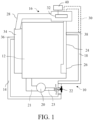
- FIG. 1 is a schematic structural diagram of a clothing handling device according to an embodiment of the present invention.
- a clothing handling device 10 including a clothing handling chamber 12; a circulation pipe 14 being in fluid communication with the clothing handling chamber 12; a gas channel 16 being in fluid communication with the clothing handling chamber 12; a flushing pipe 18 being in fluid communication with the gas channel 16; and a pressure member 20, including an input end 21 and an output end 23, the input end 21 being in communication with a bottom part of the clothing handling chamber 12, and the output end 23 being optionally in communication with one or both of the circulation pipe 14 and the flushing pipe 18, to transport a liquid.
- This embodiment of the present invention can help to ensure a power source of the circulation pipe 14 and the flushing pipe 18, and prevent pollution of a water supply pipe network and the like.
- a liquid (water) in the circulation pipe 14 and the flushing pipe 18 can obtain a power with the help of the pressure member 20, to ensure a circulation and flushing effect.
- the circulation pipe 14 and the flushing pipe 18 may be in communication with the pressure member 20 without being directly connected to the water supply pipe network, thereby eliminating or reducing the possibility that the liquid in the circulation pipe 14 and the flushing pipe 18 will flow back to the water supply pipe network because of siphoning or other reasons, causing pollution to the water supply pipe network.
- the clothing handling device 10 can pass the certification of standards and associations such as GB/T 23127, IEC: 61770, Verband Deutscher Elektrotechniker (VDE), and Deutscher ver des Gas-und Wasserfaches (DVGW).
- the clothing handling device 10 may be a washing and drying machine for washing and drying clothing.
- the clothing handling device 10 includes a switching valve 22, being located between the pressure member 20, the circulation pipe 14, and the flushing pipe 18.
- the pressure member 20 can be switched to be in communication with one or both of the circulation pipe 14 and the flushing pipe 18.
- the switching valve 22 may be a three-position switching valve with three valve positions: 0, 1, and 2. When the switching valve 22 is at the position 0, the pressure member 20 may communicate with and transport a liquid to both the circulation pipe 14 and the flushing pipe 18.
- the pressure member 20 may communicate with and transport a liquid to the circulation pipe 14.
- the pressure member 20 may communicate with and transport a liquid to the flushing pipe 18.
- the gas channel 16 includes a condenser 24, being in fluid communication with the flushing pipe 18.
- a liquid in the flushing pipe 18 can flush the condenser 24, to remove remaining fluff or dirt therein.
- the condenser 24 makes the clothing handling chamber 12 and the flushing pipe 18 communicate.
- a liquid can flow from the flushing pipe 18 through the condenser 24 and into the clothing handling chamber 12.
- the liquid may be discharged from the clothing handling device 10 through the clothing handling chamber 12 with fluff or dirt flushed out from the condenser 24, or recycled by the clothing handling chamber 12.
- the condenser 24 includes a liquid outlet 26, and the liquid outlet 26 is in fluid communication with the clothing handling chamber 12.
- a liquid discharged from the condenser 24 can enter the clothing handling chamber 12 through the liquid outlet 26.
- the liquid may be discharged from the clothing handling device 10 through the clothing handling chamber 12 with fluff or dirt flushed out from the condenser 24, or recycled by the clothing handling chamber 12.
- the clothing handling device 10 includes a drying tunnel component 28, and the flushing pipe 18 includes a branch 30 being in fluid communication with the drying tunnel component 28.
- a liquid can enter the drying tunnel component 28 through the branch 30 of the flushing pipe 18, to flush to clean fluff or dirt therein.
- clothing fluff or dirt carried by airflow may stay and accumulate in the drying tunnel component 28, blocking the drying tunnel component 28.
- a liquid enters the drying tunnel component 28 through the branch 30 of the flushing pipe 18, and can flush to clean the fluff or dirt therein, thereby reducing or avoiding a blockage of the drying tunnel component 28.
- the drying tunnel component 28 includes an impeller 32 capable of driving air to flow, and an outlet of the branch 30 is close to the impeller 32.
- clothing fluff or dirt carried by airflow may stay and accumulate in the impeller 32, affecting an operation of the impeller 32 and a flow of the driven air.
- a liquid reaches the impeller 32 through the branch 30 of the flushing pipe 18, and can flush to clean the fluff or dirt thereon, reducing or avoiding an impact of the stay and accumulation of the fluff or dirt on the impeller 32 and the air driven by the impeller 32.
- the clothing handling device 10 includes a control member 40, being arranged to rotate the impeller 32 during a communication of the pressure member 20 with the flushing pipe 18.
- the clothing handling device 10 includes a door seal 34, being in fluid communication with the drying tunnel component 28 and the clothing handling chamber 12 respectively.
- a liquid flowing out of the drying tunnel component 28 can enter the clothing handling chamber 12 through the door seal 34.
- the liquid may be discharged from the clothing handling device 10 through the clothing handling chamber 12 with fluff or dirt flushed out from the drying tunnel component 28, or recycled by the clothing handling chamber 12.
- the clothing handling device 10 includes a door seal 34, being in fluid communication with the circulation pipe 14 and the clothing handling chamber 12.
- a liquid flowing out of the circulation pipe 14 can enter the clothing handling chamber 12 through the door seal 34.
- the liquid may improve the efficiency of the clothing handling device 10 in washing clothing and the solubility of a detergent used in water in the clothing handling chamber 12.
- the pressure member 20 includes a pump.
- a power source can be provided for a liquid in one or both of the circulation pipe 14 and the flushing pipe 18.
- a position of the pressure member 20 is lower than a circulation outlet 36 of the circulation pipe 14 and a flushing outlet 38 of the flushing pipe 18.
- FIG. 2 is a schematic diagram of a liquid flow of the clothing handling device of FIG. 1 .
- the switching valve 22 when a circulation function and a flushing function of the clothing handling device 10 are enabled, the switching valve 22 is at the position 0, and the pressure member 20 may communicate with and transport a liquid 25 to the circulation pipe 14 and the flushing pipe 18.
- the liquid 25 entering the circulation pipe 14 may enter the clothing handling chamber 12 through the door seal 34, to improve the efficiency of the clothing handling device 10 in washing clothing and the solubility of a detergent used in the liquid (water).
- Part or all of the liquid 25 entering the flushing pipe 18 may enter the clothing handling chamber 12 with the flushed-out clothing fluff or dirt after flushing the condenser 24, and the liquid 25 may be recycled by the clothing handling chamber 12 or discharged from the clothing handling device 10 along with the fluff or dirt.
- Part or all of the liquid 25 entering the flushing pipe 18 may also enter the clothing handling chamber 12 with the fluff or dirt through the door seal 34 after flushing the drying tunnel component 28 such as the impeller 32 through the branch 30, and be recycled by the clothing handling chamber 12 or discharged from the clothing handling device 10 along with the fluff or dirt.
- the liquid 25 at a bottom part of the clothing handling chamber 12 may be inputted into the pressure member 20 through the input end 21 of the pressure member 20, and then outputted to the circulation pipe 14 and the flushing pipe 18 through the output end 23, and this process is repeated.
- FIG. 3 is a schematic diagram of another liquid flow of the clothing handling device of FIG. 1 .
- the switching valve 22 when a circulation function of the clothing handling device 10 is enabled, the switching valve 22 is at the position 1, and the pressure member 20 may communicate with and transport a liquid 25 to the circulation pipe 14.
- the liquid 25 entering the circulation pipe 14 may enter the clothing handling chamber 12 through the door seal 34, to improve the efficiency of the clothing handling device 10 in washing clothing and the solubility of a detergent used in water.
- the liquid 25 at a bottom part of the clothing handling chamber 12 may be inputted into the pressure member 20 through the input end 21 of the pressure member 20, and then outputted to the circulation pipe 14 through the output end 23, and this process is repeated.
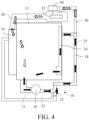
- FIG. 4 is a schematic diagram of still another liquid flow of the clothing handling device of FIG. 1 .
- the switching valve 22 when a flushing function of the clothing handling device 10 is enabled, the switching valve 22 is at the position 2, and the pressure member 20 may communicate with and transport a liquid 25 to the flushing pipe 18.
- Part or all of the liquid 25 entering the flushing pipe 18 may enter the clothing handling chamber 12 with fluff or dirt after flushing the condenser 24, and the liquid 25 may be recycled by the clothing handling chamber 12 or discharged from the clothing handling device 10 along with the fluff or dirt.
- Part or all of the liquid 25 entering the flushing pipe 18 may also enter the clothing handling chamber 12 with the fluff or dirt through the door seal 34 after flushing the drying tunnel component 28 such as the impeller 32 through the branch 30, and be recycled by the clothing handling chamber 12 or discharged from the clothing handling device 10 along with the fluff or dirt.
- the liquid 25 at a bottom part of the clothing handling chamber 12 may be inputted into the pressure member 20 through the input end 21 of the pressure member 20, and then outputted to the flushing pipe 18 through the output end 23, and this process is repeated.
Landscapes
- Engineering & Computer Science (AREA)
- Textile Engineering (AREA)
- Detail Structures Of Washing Machines And Dryers (AREA)
- Accessory Of Washing/Drying Machine, Commercial Washing/Drying Machine, Other Washing/Drying Machine (AREA)
Applications Claiming Priority (1)
| Application Number | Priority Date | Filing Date | Title |
|---|---|---|---|
| CN202111043127.8A CN115772780A (zh) | 2021-09-07 | 2021-09-07 | 衣物处理装置 |
Publications (1)
| Publication Number | Publication Date |
|---|---|
| EP4144906A1 true EP4144906A1 (de) | 2023-03-08 |
Family
ID=83049995
Family Applications (1)
| Application Number | Title | Priority Date | Filing Date |
|---|---|---|---|
| EP22191711.5A Withdrawn EP4144906A1 (de) | 2021-09-07 | 2022-08-23 | Vorrichtung zur handhabung von kleidung |
Country Status (2)
| Country | Link |
|---|---|
| EP (1) | EP4144906A1 (de) |
| CN (1) | CN115772780A (de) |
Citations (5)
| Publication number | Priority date | Publication date | Assignee | Title |
|---|---|---|---|---|
| FR2711153A1 (fr) * | 1993-10-13 | 1995-04-21 | Esswein Sa | Procédé et dispositif de nettoyage du circuit de séchage d'une machine lavante-séchante ou séchante. |
| US20080235880A1 (en) * | 2007-03-31 | 2008-10-02 | Lg Electronics Inc. | Washing machine |
| KR20140007619A (ko) * | 2012-07-09 | 2014-01-20 | 삼성전자주식회사 | 건조장치를 갖춘 세탁기 및 그 제어방법 |
| EP3192912A1 (de) * | 2016-01-14 | 2017-07-19 | BSH Hausgeräte GmbH | Wäschetrockner mit einem kühlwasserkreislauf |
| EP3241943A1 (de) * | 2016-05-03 | 2017-11-08 | BSH Hausgeräte GmbH | Haushaltsgerät mit einem wasser/prozessluft-wärmetauscher |
-
2021
- 2021-09-07 CN CN202111043127.8A patent/CN115772780A/zh active Pending
-
2022
- 2022-08-23 EP EP22191711.5A patent/EP4144906A1/de not_active Withdrawn
Patent Citations (5)
| Publication number | Priority date | Publication date | Assignee | Title |
|---|---|---|---|---|
| FR2711153A1 (fr) * | 1993-10-13 | 1995-04-21 | Esswein Sa | Procédé et dispositif de nettoyage du circuit de séchage d'une machine lavante-séchante ou séchante. |
| US20080235880A1 (en) * | 2007-03-31 | 2008-10-02 | Lg Electronics Inc. | Washing machine |
| KR20140007619A (ko) * | 2012-07-09 | 2014-01-20 | 삼성전자주식회사 | 건조장치를 갖춘 세탁기 및 그 제어방법 |
| EP3192912A1 (de) * | 2016-01-14 | 2017-07-19 | BSH Hausgeräte GmbH | Wäschetrockner mit einem kühlwasserkreislauf |
| EP3241943A1 (de) * | 2016-05-03 | 2017-11-08 | BSH Hausgeräte GmbH | Haushaltsgerät mit einem wasser/prozessluft-wärmetauscher |
Also Published As
| Publication number | Publication date |
|---|---|
| CN115772780A (zh) | 2023-03-10 |
Similar Documents
| Publication | Publication Date | Title |
|---|---|---|
| KR100441267B1 (ko) | 하수관작업용순환배수장치 | |
| US9975152B1 (en) | Air conditioner condensate drain line clean-out system | |
| CN107052010A (zh) | 一种玻璃磨边后的清洗装置 | |
| EP4144906A1 (de) | Vorrichtung zur handhabung von kleidung | |
| CN109758079A (zh) | 排水装置、排水方法及洗碗机 | |
| CN107858695A (zh) | 管道内壁酸洗钝化装置 | |
| CN217041931U (zh) | 尾气处理系统 | |
| EP2873466A1 (de) | Vorrichtung zur Dampfreduzierung für Waschmaschinen und Waschmaschine mit der Vorrichtung | |
| CN108941110A (zh) | 圆桶的自动清洗烘干系统及清洗烘干方法 | |
| JPH0978673A (ja) | 真空式下水道のリフト損失防止装置 | |
| KR101122769B1 (ko) | 드레인 파이프가 없는 워터 세퍼레이트 | |
| CN112657992A (zh) | 一体化半导体晶圆清洗机及清洗方法 | |
| SU1285307A1 (ru) | Установка дл шариковой очистки трубок теплообменников | |
| CN216560247U (zh) | 工艺水供应控制报警系统 | |
| CN212744212U (zh) | 一种风泵净化器 | |
| CN208779673U (zh) | 一种新风机吸风口粗滤网自动清洗装置 | |
| CN216106261U (zh) | 一种生物池冷凝水自动排放装置 | |
| JP2000281218A (ja) | ガス管からのドレン排出設備 | |
| CN208831334U (zh) | 矿用隔爆污水泵吸水口的防堵装置 | |
| KR20150100107A (ko) | 에어필터 세정장치 | |
| CN214813321U (zh) | 一种吸收塔氧化风管冲洗及吹扫系统 | |
| CN209464849U (zh) | 一种脱硫吸收塔入口原烟道的新型防堵塞系统 | |
| JP2020025927A (ja) | フラッシング装置 | |
| SU1754854A1 (ru) | Колодец дл канализации | |
| JP2001038315A (ja) | 配管の洗浄方法 |
Legal Events
| Date | Code | Title | Description |
|---|---|---|---|
| PUAI | Public reference made under article 153(3) epc to a published international application that has entered the european phase |
Free format text: ORIGINAL CODE: 0009012 |
|
| STAA | Information on the status of an ep patent application or granted ep patent |
Free format text: STATUS: THE APPLICATION HAS BEEN PUBLISHED |
|
| AK | Designated contracting states |
Kind code of ref document: A1 Designated state(s): AL AT BE BG CH CY CZ DE DK EE ES FI FR GB GR HR HU IE IS IT LI LT LU LV MC MK MT NL NO PL PT RO RS SE SI SK SM TR |
|
| STAA | Information on the status of an ep patent application or granted ep patent |
Free format text: STATUS: REQUEST FOR EXAMINATION WAS MADE |
|
| 17P | Request for examination filed |
Effective date: 20230908 |
|
| RBV | Designated contracting states (corrected) |
Designated state(s): AL AT BE BG CH CY CZ DE DK EE ES FI FR GB GR HR HU IE IS IT LI LT LU LV MC MK MT NL NO PL PT RO RS SE SI SK SM TR |
|
| STAA | Information on the status of an ep patent application or granted ep patent |
Free format text: STATUS: THE APPLICATION IS DEEMED TO BE WITHDRAWN |
|
| 18D | Application deemed to be withdrawn |
Effective date: 20230909 |