EP4144672A1 - Article transport vehicle - Google Patents
Article transport vehicle Download PDFInfo
- Publication number
- EP4144672A1 EP4144672A1 EP22193261.9A EP22193261A EP4144672A1 EP 4144672 A1 EP4144672 A1 EP 4144672A1 EP 22193261 A EP22193261 A EP 22193261A EP 4144672 A1 EP4144672 A1 EP 4144672A1
- Authority
- EP
- European Patent Office
- Prior art keywords
- vehicle body
- placement
- drive source
- swing arm
- transfer drive
- Prior art date
- Legal status (The legal status is an assumption and is not a legal conclusion. Google has not performed a legal analysis and makes no representation as to the accuracy of the status listed.)
- Pending
Links
Images


Classifications
-
- B—PERFORMING OPERATIONS; TRANSPORTING
- B65—CONVEYING; PACKING; STORING; HANDLING THIN OR FILAMENTARY MATERIAL
- B65G—TRANSPORT OR STORAGE DEVICES, e.g. CONVEYORS FOR LOADING OR TIPPING, SHOP CONVEYOR SYSTEMS OR PNEUMATIC TUBE CONVEYORS
- B65G1/00—Storing articles, individually or in orderly arrangement, in warehouses or magazines
- B65G1/02—Storage devices
- B65G1/04—Storage devices mechanical
- B65G1/137—Storage devices mechanical with arrangements or automatic control means for selecting which articles are to be removed
- B65G1/1373—Storage devices mechanical with arrangements or automatic control means for selecting which articles are to be removed for fulfilling orders in warehouses
- B65G1/1378—Storage devices mechanical with arrangements or automatic control means for selecting which articles are to be removed for fulfilling orders in warehouses the orders being assembled on fixed commissioning areas remote from the storage areas
-
- B—PERFORMING OPERATIONS; TRANSPORTING
- B65—CONVEYING; PACKING; STORING; HANDLING THIN OR FILAMENTARY MATERIAL
- B65G—TRANSPORT OR STORAGE DEVICES, e.g. CONVEYORS FOR LOADING OR TIPPING, SHOP CONVEYOR SYSTEMS OR PNEUMATIC TUBE CONVEYORS
- B65G17/00—Conveyors having an endless traction element, e.g. a chain, transmitting movement to a continuous or substantially-continuous load-carrying surface or to a series of individual load-carriers; Endless-chain conveyors in which the chains form the load-carrying surface
- B65G17/12—Conveyors having an endless traction element, e.g. a chain, transmitting movement to a continuous or substantially-continuous load-carrying surface or to a series of individual load-carriers; Endless-chain conveyors in which the chains form the load-carrying surface comprising a series of individual load-carriers fixed, or normally fixed, relative to traction element
-
- B—PERFORMING OPERATIONS; TRANSPORTING
- B65—CONVEYING; PACKING; STORING; HANDLING THIN OR FILAMENTARY MATERIAL
- B65G—TRANSPORT OR STORAGE DEVICES, e.g. CONVEYORS FOR LOADING OR TIPPING, SHOP CONVEYOR SYSTEMS OR PNEUMATIC TUBE CONVEYORS
- B65G1/00—Storing articles, individually or in orderly arrangement, in warehouses or magazines
- B65G1/02—Storage devices
- B65G1/04—Storage devices mechanical
- B65G1/0492—Storage devices mechanical with cars adapted to travel in storage aisles
-
- B—PERFORMING OPERATIONS; TRANSPORTING
- B60—VEHICLES IN GENERAL
- B60P—VEHICLES ADAPTED FOR LOAD TRANSPORTATION OR TO TRANSPORT, TO CARRY, OR TO COMPRISE SPECIAL LOADS OR OBJECTS
- B60P1/00—Vehicles predominantly for transporting loads and modified to facilitate loading, consolidating the load, or unloading
- B60P1/04—Vehicles predominantly for transporting loads and modified to facilitate loading, consolidating the load, or unloading with a tipping movement of load-transporting element
- B60P1/28—Tipping body constructions
- B60P1/283—Elements of tipping devices
-
- B—PERFORMING OPERATIONS; TRANSPORTING
- B60—VEHICLES IN GENERAL
- B60Q—ARRANGEMENT OF SIGNALLING OR LIGHTING DEVICES, THE MOUNTING OR SUPPORTING THEREOF OR CIRCUITS THEREFOR, FOR VEHICLES IN GENERAL
- B60Q1/00—Arrangement of optical signalling or lighting devices, the mounting or supporting thereof or circuits therefor
- B60Q1/26—Arrangement of optical signalling or lighting devices, the mounting or supporting thereof or circuits therefor the devices being primarily intended to indicate the vehicle, or parts thereof, or to give signals, to other traffic
- B60Q1/50—Arrangement of optical signalling or lighting devices, the mounting or supporting thereof or circuits therefor the devices being primarily intended to indicate the vehicle, or parts thereof, or to give signals, to other traffic for indicating other intentions or conditions, e.g. request for waiting or overtaking
- B60Q1/543—Arrangement of optical signalling or lighting devices, the mounting or supporting thereof or circuits therefor the devices being primarily intended to indicate the vehicle, or parts thereof, or to give signals, to other traffic for indicating other intentions or conditions, e.g. request for waiting or overtaking for indicating other states or conditions of the vehicle
-
- B—PERFORMING OPERATIONS; TRANSPORTING
- B62—LAND VEHICLES FOR TRAVELLING OTHERWISE THAN ON RAILS
- B62D—MOTOR VEHICLES; TRAILERS
- B62D63/00—Motor vehicles or trailers not otherwise provided for
- B62D63/02—Motor vehicles
-
- B—PERFORMING OPERATIONS; TRANSPORTING
- B65—CONVEYING; PACKING; STORING; HANDLING THIN OR FILAMENTARY MATERIAL
- B65G—TRANSPORT OR STORAGE DEVICES, e.g. CONVEYORS FOR LOADING OR TIPPING, SHOP CONVEYOR SYSTEMS OR PNEUMATIC TUBE CONVEYORS
- B65G1/00—Storing articles, individually or in orderly arrangement, in warehouses or magazines
- B65G1/02—Storage devices
- B65G1/04—Storage devices mechanical
- B65G1/06—Storage devices mechanical with means for presenting articles for removal at predetermined position or level
- B65G1/065—Storage devices mechanical with means for presenting articles for removal at predetermined position or level with self propelled cars
-
- B—PERFORMING OPERATIONS; TRANSPORTING
- B65—CONVEYING; PACKING; STORING; HANDLING THIN OR FILAMENTARY MATERIAL
- B65G—TRANSPORT OR STORAGE DEVICES, e.g. CONVEYORS FOR LOADING OR TIPPING, SHOP CONVEYOR SYSTEMS OR PNEUMATIC TUBE CONVEYORS
- B65G47/00—Article or material-handling devices associated with conveyors; Methods employing such devices
- B65G47/74—Feeding, transfer, or discharging devices of particular kinds or types
- B65G47/94—Devices for flexing or tilting travelling structures; Throw-off carriages
- B65G47/96—Devices for tilting links or platform
- B65G47/962—Devices for tilting links or platform tilting about an axis substantially parallel to the conveying direction
Definitions
- the present invention relates to an article transport vehicle that transports an article and includes a vehicle body frame, a vehicle body cover, a wheel supported by the vehicle body frame, a wheel drive source, a placement body on which an article is placed, and a transfer drive mechanism that drives the placement body to transfer the article.
- JP H5-221516A discloses an article transport vehicle (1) that includes transfer devices (15, 16, 17) that serve as placement bodies on which articles are placed, a base (3) that serves as a vehicle body frame on which the transfer devices are placed, and a lift motor (4) that serves as a transfer drive mechanism for transferring articles and moves the base up and down together with the transfer devices. It is possible to engage the transfer devices (15, 16, 17), which are attachments of different types, and the base (3) without using a bolt or the like, and thus the transfer devices (15, 16, 17) can be attached to and detached from the base (3). That is, it is possible to easily replace the transfer devices (15, 16, 17) according to an article to be transported or a transport work.
- the transfer devices (15, 16, 17) are configured to be easily replaceable, but the lift motor (4) is housed in the base (3).
- the lift motor (4) is not configured to be easily replaceable when the lift motor has broken down or deteriorated over time, for example.
- a drive source for driving wheels, a power supply for supplying driving powerto the drive source and the lift motor (4), and a transfer drive mechanism for moving the transfer devices (15, 16, 17) up and down are also housed in the base (3), and it cannot be said that maintenance of these is not easy as well.
- an article transport vehicle is configured to transport an article and includes: a vehicle body frame; a vehicle body cover; a wheel supported in such a manner as to be rotatable relative to the vehicle body frame; a wheel drive source configured to drive the wheel; a placement body including a placement surface on which the article is placeable; and a transfer drive mechanism configured to drive the placement body to transfer the article
- the transfer drive mechanism includes: a transfer drive source; and a transmission mechanism configured to transmit driving force from the transfer drive source to the placement body, the transmission mechanism includes: an output member coupled to an output shaft of the transfer drive source; and a driven member configured to be driven by the output member, the placement body moves in conjunction with the driven member, the driven member is not coupled to the output member and is configured to operate by being pressed by the output member, the wheel drive source, the transfer drive source, and the output member are supported by the vehicle body frame, the placement body and the driven member are supported by the vehicle body cover, and the vehicle body cover covers the wheel drive source and the transfer drive source
- the placement body and the driven member are supported by the vehicle body cover, and the wheel drive source, the transfer drive source, and the output member are supported by the vehicle body frame.
- the driven member that operates by being pressed by the output member is not coupled to the output member. That is, the vehicle body cover is attached to the vehicle body frame in such a manner as to be attachable to and detachable from the vehicle body frame while supporting the placement body and the driven member.
- the vehicle body cover covers the wheel drive source and the transfer drive source, and accordingly, when the vehicle body cover is removed from the vehicle body frame, maintenance of the wheel drive source and the transfer drive source can be easily performed.
- the output member is coupled to the output shaft of the transfer drive source, and accordingly, maintenance of the output member can be easily performed as well.
- the article transport facility F includes a traveling surface Ff on which article transport vehicles V travel, article supply sections 109 for supplying transport target articles W to the article transport vehicles V, and receiving sections I for receiving articles W transported by the article transport vehicles V.
- the traveling surface Ff is formed as a spreading flat surface, and passages R along which the article transport vehicles V travel are set on the traveling surface Ff.
- the receiving sections I are provided at a plurality of positions on the traveling surface Ff. In the present embodiment, each of the receiving sections I provided at the plurality of positions includes a receiving opening Ia through which an article W is guided to a position below the traveling surface Ff.
- the article transport facility F includes a transport section T for transporting containers C for storing articles W, an empty container supply section 108 for supplying containers C (empty containers Ce) not storing any article W, and a shipping section 107 for shipping containers C (filled containers Cf) storing at least one article W received from the article transport vehicles V via the receiving sections I (receiving openings Ia).
- the transport section T is arranged below the traveling surface Ff described above.
- the transport section T includes an empty container loading section T8 for receiving empty containers Ce supplied from the empty container supply section 108, a filled container unloading section T7 for discharging filled containers Cf storing articles W received in the receiving sections I, and receiving/transporting sections Ti provided so as to connect the empty container loading section T8 and the filled container unloading section T7.
- the transport section T includes a plurality of receiving/transporting sections Ti, and each of the receiving/transporting sections Ti is provided so as to connect the empty container loading section T8 and the filled container unloading section T7.
- the plurality of receiving/transporting sections Ti are arranged side by side in parallel in a plan view.
- the empty container loading section T8, the filled container unloading section T7, and the receiving/transporting sections Ti are each constituted by a conveyor.
- the receiving sections I are arranged in such a manner as to be overlapped with the receiving/transporting sections Ti when viewed in the up-down direction.
- Containers C are arranged at positions corresponding to the receiving sections I in the receiving/transporting sections Ti. Accordingly, articles W received from the article transport vehicles V in the receiving sections I are guided through the receiving openings Ia to positions below the traveling surface Ff, and are then stored in containers C arranged in the receiving/transporting sections Ti (see FIGS. 3 and 4 , for example).
- a plurality of receiving sections I are arranged side by side with each other for each of the receiving/transporting sections Ti.
- a container C is arranged at a position corresponding to each of the receiving sections I, or more specifically at a position directly under each of the receiving sections I.
- the article transport facility F includes shutters S (see FIGS. 3 and 4 ) for opening and closing the receiving openings Ia.
- Each shutter S keeps the corresponding receiving opening Ia closed until the receiving section I has received at least one article W that is to be sorted based on sorting information (see FIG. 3 ).
- the shutter S then opens the receiving opening Ia after the receiving section I has received at least one article Wthat is to be sorted based on the sorting information (see FIG. 4 ).
- the articles W sorted to the receiving sections I by the article transport vehicles V pass through the receiving openings Ia and are guided to positions below the traveling surface Ff, and are stored in containers C arranged in the receiving/transporting sections Ti.
- an article W for which a specified receiving section I has been designated as a transport destination based on the sorting information is supplied to an article transport vehicle V by a supply entity such as a worker or a robot, for example.
- the article transport vehicle V that received the article W in the article supply section 109 then travels along a passage R defined on the traveling surface Ff, and transports the article Wto the receiving section I that was designated based on the sorting information.
- Each of the receiving sections I is provided with a position information holder (not shown) that holds position information indicating a position corresponding to the receiving section I.
- An article transport vehicle V travels toward a specified receiving section I that was designated as a transport destination, and when a position information detector (not shown) detects the position information held by the position information holder that corresponds to the specified receiving section I, the article transport vehicle V stops at that position (or transitions to a low-speed traveling state) and transfers an article W to that receiving section I.
- the position information holder is constituted by, for example, an indicator such as a barcode (e.g., a two-dimensional barcode) that indicates position information, a storage element such as an RFID tag (radio frequency identifier tag) that stores position information, or a signal transmitter such as a beacon that emits a signal indicating position information.
- a barcode e.g., a two-dimensional barcode
- RFID tag radio frequency identifier tag
- a signal transmitter such as a beacon that emits a signal indicating position information.
- the position information detector is configured as a barcode reader
- the position information detector is configured as an RFID tag
- the position information detector is configured as an RFID reader
- the position information detector is configured as a beacon
- the position information detector is configured as a signal receiver.
- the article transport facility F is configured by arranging a plurality of frame units 100 (see FIG. 5 ) side by side in a grid pattern in a plan view as shown in FIGS. 1 and 2 .
- Each frame unit 100 includes the traveling surface Ff in which three receiving openings Ia are arranged on each of two sides of a passage R, and receiving/transporting sections Ti arranged in two rows in such a manner as to be overlapped with the traveling surface Ff (the receiving openings Ia) when viewed in the up-down direction.
- the traveling surface Ff the receiving openings Ia
- FIG. 1 one of the plurality of frame units 100 is denoted by the reference sign.
- 21 receiving sections I are provided for each receiving/transporting section Ti, and the empty container loading section T8 and the filled container unloading section T7 each transport 21 containers C synchronously as a container group.
- the receiving/transporting sections Ti each transport a group of 21 containers C after articles W have been stored in all of the 21 containers C included in that container group.
- each article transport vehicle V travels along a passage R defined on the traveling surface Ff (see FIG. 1 ) with an article W placed on a placement body 3 and transports the article W from an article supply section 109 to a receiving section I.
- the article transport vehicle V transfers the article W from the placement body 3 to a receiving opening Ia by tilting the placement body 3 beside the receiving opening Ia.
- a direction extending along a first axis A1 which is a swing axis about which the placement body 3 is caused to swing to be tilted as described later, will be referred to as an axial direction L of the article transport vehicle V extending along a horizontal plane.
- the axial direction L extends along the traveling direction X, and when the article transport vehicle V travels straight, the axial direction L matches the traveling direction X.
- a direction orthogonal to the axial direction L in a plan view will be referred to as a vehicle body width direction H.
- the vehicle body width direction H matches a width direction Y.
- One side in the vehicle body width direction H will be referred to as a first side H1 in the vehicle body width direction, and the other side will be referred to as a second side H2 in the vehicle body width direction.
- the article transport vehicle V includes a carriage body 10 that includes a vehicle body frame 1 and a vehicle body cover 2 and a transfer device 30 that is mounted on the carriage body 10, and the article transport vehicle V transports an article W.
- the article transport vehicle V also includes a wheel 9 (see FIGS. 6 and 7 ) that is supported in such a manner as to be rotatable relative to the vehicle body frame 1 and a wheel drive source 90 (see FIG. 7 ) that drives the wheel 9.
- the wheel drive source 90 is an electric motor, for example, and operates by being supplied with power from a power storage body B (see FIG. 16 ), such as a storage battery or a capacitor, mounted on the article transport vehicle V.
- a power storage body B see FIG. 16
- the transfer device 30 includes the placement body 3 that includes a placement surface 3a on which an article W is placeable, a coupling mechanism 6 that couples the placement body 3 and the carriage body 10, and a transfer drive mechanism 4 that drives the placement body 3 to transfer the article W.
- the placement body 3 is shaped as a tray with an edge portion of the plate-shaped placement surface 3a protruding upward, and an article W is placed on the upper side of the placement surface 3a.
- the carriage body 10 includes an opposing surface 2a that faces a lower surface 3b of the placement body 3.
- the placement body 3 provided above the carriage body 10 is configured to swing relative to the carriage body 10 about an axis extending along the axial direction L. That is, the placement body 3 is configured to swing between a reference position at which the placement body 3 extends along the opposing surface 2a of the carriage body 10 and a standing position at which the placement body 3 is tilted relative to the opposing surface 2a.
- the transfer drive mechanism 4 is a mechanism for changing an angle of the placement surface 3a.
- the transfer device 30 includes a transfer drive source 40 that is constituted by a motor or the like.
- the transfer device 30 is configured to cause the placement body 3 to swing relative to the carriage body 10 about an axis (the first axis A1 or a third axis A3) extending along the axial direction L (the traveling direction X).
- the transfer device 30 tilts the placement body 3 in the vehicle body width direction H (the width direction Y) to cause the article W to slide in the width direction Y on the placement body 3, and thus transfer the article W to a transfer location outward of the article transport vehicle V in the vehicle body width direction H (the width direction Y).
- the transfer device 30 is configured to cause the placement body 3 to swing relative to the carriage body 10 about the first axis A1 (see FIGS. 12 and 13 ), as well as about the third axis A3 (see FIGS. 14 and 15 ). That is, the article transport vehicle V is capable of transferring an article W to each of receiving sections I (transfer locations) respectively arranged on the first side H1 and the second side H2 in the vehicle body width direction (a first side Y1 and a second side Y2 in the width direction) relative to the article transport vehicle V by causing the placement body 3 to swing.
- FIG. 3 shows a state in which articles W are transferred to a receiving section I that is on the first side Y1 in the width direction (the first side H1 in the vehicle body width direction) when viewed from the article transport vehicle V.
- a first coupling mechanism 6A and a second coupling mechanism 6B are provided as the coupling mechanism 6, and a first transfer drive mechanism 4A and a second transfer drive mechanism 4B are provided as the transfer drive mechanism 4.
- the first coupling mechanism 6A couples the placement body 3 and the carriage body 10 in such a manner that the placement body 3 is swingable relative to the carriage body 10 about the first axis A1 extending along the horizontal plane.
- the first transfer drive mechanism 4A includes a first swing arm 51 (a swing arm 50) that swings about a second axis A2 parallel to the first axis A1 and a first transfer drive source 41 that causes the first swing arm 51 to swing.
- the second coupling mechanism 6B couples the placement body 3 and the carriage body 10 in such a manner that the placement body 3 is swingable relative to the carriage body 10 about the third axis A3 extending along the horizontal plane.
- the second transfer drive mechanism 4B includes a second swing arm 52 (a swing arm 50) that swings about a fourth axis A4 parallel to the third axis A3 and a second transfer drive source 42 that causes the second swing arm 52 to swing.
- the third axis A3 is parallel to the first axis A1, and the first axis A1, the second axis A2, the third axis A3, and the fourth axis A4 are parallel to each other.
- a configuration is described as an example in which the first axis A1 and the second axis A2 are separate axes, but the first axis A1 and the second axis A2 may be the same axis.
- a configuration is described as an example in which the third axis A3 and the fourth axis A4 are separate axes, but the third axis A3 and the fourth axis A4 may be the same axis.
- the common transfer drive source 40 (a motor) serves as the first transfer drive source 41 and the second transfer drive source 42 as described later.
- an output member 7 that is coupled to an output shaft 47 of the transfer drive source 40 is common to the first transfer drive source 41 and the second transfer drive source 42. The output member 7 is also included in the transfer drive mechanism 4.
- Each swing arm 50 is formed in such a manner as to extend along the vehicle body width direction H and swings between a reference position (see FIGS. 13 and 15 ) at which the swing arm 50 extends along the opposing surface 2a and a standing position (see FIGS. 12 and 14 ) at which the swing arm 50 is tilted relative to the opposing surface 2a.
- the placement body 3 is at a horizontal position at which the placement surface 3a extends along the horizontal plane as shown in FIGS. 13 and 15 , for example. As shown in FIGS.
- the placement body 3 swings due to being pressed by the swing arm 50 from a lower side, and when the swing arm 50 is at the standing position, the placement body 3 is at a tilted position at which the placement surface 3a is tilted relative to the horizontal plane.
- the first swing arm 51 is formed in such a manner as to extend along a direction (the vehicle body width direction H) orthogonal to the second axis A2 and swings between the reference position (see FIGS. 7 , 8 , 11 , and 13 , for example) at which the first swing arm 51 extends along the opposing surface 2a and the standing position (see FIGS. 10 and 12 , for example) at which the first swing arm 51 is tilted relative to the opposing surface 2a.
- the placement body 3 is at the horizontal position (see FIGS. 6 , 11 , and 13 , for example) at which the placement surface 3a extends along the horizontal plane.
- the placement body 3 While the first swing arm 51 moves from the horizontal position to the standing position, the placement body 3 swings due to being pressed by the first swing arm 51 from the lower side Z2, and when the first swing arm 51 is at the standing position, the placement body 3 is at the tilted position (a first tilted position, see FIGS. 10 and 12 ) at which the placement surface 3a is tilted relative to the horizontal plane. At the first tilted position, the placement surface 3a is tilted in such a manner as to face the first side H1 in the vehicle body width direction.
- the second swing arm 52 is formed in such a manner as to extend along a direction (the vehicle body width direction H) orthogonal to the fourth axis A4 and swings between the reference position (see FIGS. 7 , 8 , 11 , and 15 , for example) at which the second swing arm 52 extends along the opposing surface 2a and the standing position (see FIG. 14 , for example) at which the second swing arm 52 is tilted relative to the opposing surface 2a.
- the placement body 3 is at the horizontal position (see FIGS. 6 , 11 , and 15 , for example) at which the placement surface 3a extends along the horizontal plane.
- the placement body 3 While the second swing arm 52 moves from the horizontal position to the standing position, the placement body 3 swings due to being pressed by the second swing arm 52 from the lower side Z2, and when the second swing arm 52 is at the standing position, the placement body 3 is at the tilted position (a second tilted position, see FIG. 14 ) at which the placement surface 3a is tilted relative to the horizontal plane. At the second tilted position, the placement surface 3a is tilted in such a manner as to face the second side H2 in the vehicle body width direction.
- the swing arms 50 for tilting the placement surface 3a in respective directions are each disposed at a position in the axial direction L. That is, the single first swing arm 51 for tilting the placement surface 3a to the first tilted position is disposed at a position in the axial direction L, and the single second swing arm 52 for tilting the placement surface 3a to the second tilted position is disposed at a position in the axial direction L. Also, the first swing arm 51 and the second swing arm 52 are disposed adjacent to each other in the axial direction L.
- the present embodiment includes support arms 60, which will be described later, extending in parallel to the swing arms 50 to assist a positional change of the placement body 3 caused by the swing arms 50 and keep the placement body 3 (the placement surface 3a) from warping.
- the transfer device 30 includes the coupling mechanism 6 that couples the placement body 3 and the carriage body 10, and the support arms 60 constitute a part of the coupling mechanism 6.
- the first coupling mechanism 6A and the second coupling mechanism 6B are provided as the coupling mechanism 6.
- the first coupling mechanism 6A couples the placement body 3 and the carriage body 10 (the vehicle body cover 2) in such a manner that the placement body 3 is swingable relative to the carriage body 10 about the first axis A1 extending along the horizontal plane.
- the first coupling mechanism 6A includes a first support arm 61 (a support arm 60) that swings about the first axis A1 and a first fulcrum support portion 63 (a fulcrum support portion 67) that supports a swing fulcrum of the first support arm 61.
- the first support arm 61 is swingably coupled to the placement body 3 at a first coupling portion 65 (a coupling portion 69) that is set in an end portion of the first support arm 61 opposite to the first fulcrum support portion 63.
- the first support arm 61 is formed in such a manner as to extend along a direction (the vehicle body width direction H) orthogonal to the first axis A1 and swings between a support reference position (a first support reference position: see FIGS. 7 , 8 , and 13 , for example) at which the first support arm 61 extends along the opposing surface 2a and a support standing position (a first support standing position: see FIGS. 10 and 12 ) at which the first support arm 61 is tilted relative to the opposing surface 2a.
- a support reference position a first support reference position: see FIGS. 7 , 8 , and 13 , for example
- a support standing position a first support standing position at which the first support arm 61 is tilted relative to the opposing surface 2a.
- the first support arm 61 swings relative to the vehicle body cover 2 (the carriage body 10) at the first fulcrum support portion 63 coupled to the carriage body 10.
- the first support arm 61 changes its position together with the placement body 3 without swinging.
- the first support arm 61 When the placement body 3 is caused to swing by the second swing arm 52, the first support arm 61 does not swing together with the placement body 3 and remains at the support reference position (the first support reference position). That is, the first support arm 61 does not swing relative to the vehicle body cover 2 (the carriage body 10) at the first fulcrum support portion 63 coupled to the carriage body 10.
- the first support arm 61 swings relative to the placement body 3 because the placement body 3 swings. That is, the placement body 3 and the first support arm 61 swing relative to each other at the first coupling portion 65, and thus the first support arm 61 remains at the first support reference position.
- the second coupling mechanism 6B couples the placement body 3 and the carriage body 10 in such a manner that the placement body 3 is swingable relative to the carriage body 10 about the third axis A3 extending along the horizontal plane.
- the second coupling mechanism 6B includes a second support arm 62 (a support arm 60) that swings about the third axis A3 and a second fulcrum support portion 64 (a fulcrum support portion 67) that supports a swing fulcrum of the second support arm 62.
- the second support arm 62 is swingably coupled to the placement body 3 at a second coupling portion 66 (a coupling portion 69) that is set in an end portion of the second support arm 62 opposite to the second fulcrum support portion 64.
- the second support arm 62 is formed in such a manner as to extend along a direction (the vehicle body width direction H) orthogonal to the third axis A3 and swings between a support reference position (a second support reference position: see FIGS. 7 , 8 , and 15 , for example) at which the second support arm 62 extends along the opposing surface 2a and a support standing position (a second support standing position: see FIG. 14 ) at which the second support arm 62 is tilted relative to the opposing surface 2a.
- a support reference position a second support reference position: see FIGS. 7 , 8 , and 15 , for example
- a support standing position a second support standing position at which the second support arm 62 is tilted relative to the opposing surface 2a.
- the second support arm 62 swings relative to the vehicle body cover 2 (the carriage body 10) at the second fulcrum support portion 64 coupled to the carriage body 10.
- the second support arm 62 changes its position together with the placement body 3 without swinging.
- the second support arm 62 When the placement body 3 is caused to swing by the first swing arm 51, the second support arm 62 does not swing together with the placement body 3 and remains at the support reference position (the second support reference position). That is, the second support arm 62 does not swing relative to the vehicle body cover 2 (the carriage body 10) at the second fulcrum support portion 64 coupled to the carriage body 10.
- the second support arm 62 swings relative to the placement body 3 because the placement body 3 swings. That is, the placement body 3 and the second support arm 62 swing relative to each other at the second coupling portion 66, and thus the second support arm 62 remains at the second support reference position.
- the transfer drive mechanism 4 includes the transfer drive source 40 and a transmission mechanism 5 for transmitting driving force from the transfer drive source 40 to the placement body 3.
- the transmission mechanism 5 includes the swing arms 50 and the output member 7 that is coupled to the transfer drive source 40.
- the output member 7 transmits driving force from the transfer drive source 40 to the swing arms 50, and the driving force is transmitted to the placement body 3 via the swing arms 50.
- the swing arms 50 constituting the transmission mechanism 5 can be said to be driven members that are driven by the output member 7.
- the transmission mechanism 5 includes the output member 7 that is coupled to the output shaft 47 of the transfer drive source 40 and is shaped as a lever that swings about a rotation axis (an output axis AO) of the output shaft 47.
- the swing arms 50 are driven by the output member 7.
- Pressing rollers 75 that come into contact with the swing arms 50 and cause the swing arms 50 to swing are provided in two end portions of the output member 7 in the vehicle body width direction H.
- Each swing arm 50 includes a cam portion 57 protruding toward the lower side Z2, and the pressing rollers 75 respectively come into contact with the cam portions 57.
- the swing arms 50 are not coupled to the output member 7 and are configured to operate by being pressed by the output member 7. As a result of the pressing rollers 75 pressing the swing arms 50 along the cam portions 57, the swing arms 50 swing about the output axis AO.
- the pressing roller 75 (a first pressing roller 75a) disposed on the second side H2 in the vehicle body width direction comes into contact with the cam portion 57 of the first swing arm 51 and presses the cam portion 57 to change the position of the first swing arm 51 from the reference position (see FIGS. 11 and 13 ) to the standing position ( FIG. 12 ).
- the output member 7 is caused to swing in a second swing direction D2 shown in FIG.
- the pressing roller 75 (a second pressing roller 75b) disposed on the first side H1 in the vehicle body width direction comes into contact with the cam portion 57 of the second swing arm 52 and presses the cam portion 57 to change the position of the second swing arm 52 from the reference position (see FIGS. 11 and 15 ) to the standing position ( FIG. 14 ).
- the placement body 3 changes its position between the horizontal position and the tilted positions in conjunction with the swing arms 50, which serve as driven members.
- the present embodiment includes the support arms 60 provided in parallel to the swing arms 50 to assist a positional change of the placement body 3 caused by the swing arms 50 and keep the placement body 3 (the placement surface 3a) from warping.
- two support arms 60 are disposed so as to sandwich the first swing arm 51 in the axial direction L to support the placement body 3 when the position of the placement surface 3a is changed to the first tilted position by the first swing arm 51. That is, the first swing arm 51 is disposed between two first support arms 61 in the axial direction L.
- two support arms 60 are disposed so as to sandwich the second swing arm 52 in the axial direction L to support the placement body 3 when the position of the placement surface 3a is changed to the second tilted position by the second swing arm 52. That is, the second swing arm 52 is disposed between two second support arms 62 in the axial direction L. As described above, two support arms 60 are provided for each swing arm 50, and therefore, it is possible to keep the placement body 3 (the placement surface 3a) from warping when the position of the placement body 3 is changed by the swing arm 50.
- recessed grooves 25 for housing the swing arms 50 and the support arms 60 are formed in the opposing surface 2a of the vehicle body cover 2.
- the recessed groove 25 for housing the swing arms 50 and a recessed groove 25 for housing the support arms 60 are distinguished from each other, the recessed groove 25 for housing the swing arms 50 will be referred to as a swing arm housing groove 255, and the recessed groove 25 for housing the support arms 60 will be referred to as a support arm housing groove 256.
- Each swing arm 50 is swingably supported by the vehicle body cover 2 (the carriage body 10) at a swing support portion 54 on one end side in the vehicle body width direction H.
- the other end of the swing arm 50 is a free end that is provided with a contact roller 53.
- the contact roller 53 moves in the vehicle body width direction H while being in contact with the lower surface 3b of the placement body 3, and thus changes the position of the placement surface 3a of the placement body 3 from the horizontal position to the tilted position.
- the swing arm 50 changes its position by being pressed by the output member 7 as described above.
- the swing arm housing groove 255 is open to allow the output member 7 to move past the opposing surface 2a toward the upper side Z1. That is, the swing arm housing groove 255 is formed as an opening 27, and it can be said that the vehicle body cover 2 includes the opening 27 through which the output member 7 passes in the up-down direction Z.
- each support arm 60 in the vehicle body width direction H is swingably supported by the vehicle body cover 2, and the other end of the support arm 60 in the vehicle body width direction H is swingably supported by the lower surface 3b of the placement body 3.
- the placement body 3 is attached to the vehicle body cover 2 via the support arm 60 in such a manner as to be swingable relative to the vehicle body cover 2.
- the support arm housing groove 256 is shaped as a groove and does not extend through the vehicle body cover 2 in the up-down direction Z.
- the placement body 3, the swing arms 50 (the driven members), and the support arms 60 are supported by the vehicle body cover 2.
- the wheel drive source 90, the transfer drive source 40, and the output member 7 are supported by the vehicle body frame 1.
- the vehicle body cover 2 covers the wheel drive source 90 and the transfer drive source 40.
- the swing arms 50 driven by the output member 7 are not coupled to the output member 7 and are configured to operate by being pressed by the output member 7. Accordingly, the vehicle body cover 2 is attached to the vehicle body frame 1 in such a manner as to be attachable to and detachable from the vehicle body frame 1 while supporting the placement body 3, the swing arms 50, and the support arms 60.
- FIG. 16 shows an example of a state where the vehicle body cover 2 is removed from the vehicle body frame 1.
- the swing arms 50 and the support arms 60 are also shown using imaginary lines to clarify the relationship between the swing arms 50 and the output member 7 and the relationship between the swing arms 50 and the support arms 60.
- the swing arms 50 are removed from the vehicle body frame 1 together with the vehicle body cover 2, and therefore, the output member 7 is exposed and maintenance of the output member 7 can be easily performed.
- the pressing rollers 75 can be easily replaced when worn out.
- the transfer drive source 40 is disposed on the lower side Z2 of the support arms 60, but the support arms 60 are removed from the vehicle body frame 1 together with the vehicle body cover 2, and therefore, the transfer drive source 40 is exposed and maintenance of the transfer drive source 40 can be easily performed.
- the power storage body B is disposed on the lower side Z2 of the support arms 60 as shown in FIG. 16 . It is known that the power storage capability of the power storage body B such as a storage battery or a capacitor degrades over time. When the power storage capability has degraded to be lower than or equal to a prescribed level, the power storage body B is replaced. In the present embodiment, the support arms 60 are removed from the vehicle body frame 1 together with the vehicle body cover 2, and therefore, the power storage body B is exposed and can be easily replaced.
- the vehicle body cover 2 includes a top surface portion 21 that faces the lower surface 3b of the placement body 3 and covers the wheel drive source 90 and the transfer drive source 40 from the upper side, and a side wall portion 23 that extends from an outer edge portion of the top surface portion 21 toward the lower side.
- a lower end 23t of the side wall portion 23 is on the lower side Z2 of an upper end 9t of the wheel 9. That is, the side wall portion 23 covers a side surface of the wheel 9.
- the vehicle body cover 2 can be easily removed and therefore, the maintenance is facilitated.
- the article transport vehicle V is configured to be capable of being stopped when there is an abnormality in the article transport facility F or the individual article transport vehicle V, for example.
- the article transport vehicle V includes a stop switch SW for stopping the wheel drive source 90 and the transfer drive source 40 as shown in FIGS. 7 and 8 , for example.
- the stop switch SW is supported by the vehicle body frame 1, and the vehicle body cover 2 includes a stop switch opening 29 formed at a position corresponding to the stop switch SW.
- Such a stop switch SW is often electrically connected to the wheel drive source 90 and the transfer drive source 40 or a control device (not shown) for controlling the wheel drive source 90 and the transfer drive source 40 via connecting wires. Accordingly, if the stop switch SW is supported by the vehicle body cover 2, the vehicle body cover 2 cannot be removed from the vehicle body frame 1 unless the connecting wires are removed. If the stop switch SW is supported by the vehicle body frame 1 as in the present embodiment, there is no need to remove the connecting wires when removing the vehicle body cover 2 from the vehicle body frame 1. Also, the vehicle body cover 2 includes the stop switch opening 29, and therefore, the stop switch SW can be easily operated from the outside even if the stop switch SW is supported by the vehicle body frame 1.
- the article transport vehicle V includes a display lamp LP that serves as an indicator that indicates a state of a section of the article transport vehicle V, such as a driving state of the wheel drive source 90, a driving state of the transfer drive source 40, the position of the placement body 3, and a charge amount of the power storage body B (a storage battery, a capacitor, etc.).
- the present embodiment includes a plurality of display lamps LP, and a display lamp substrate LPA on which the display lamps LP are mounted is supported by the vehicle body frame 1.
- the vehicle body cover 2 attached to the vehicle body frame 1 covers the display lamps LP, but the vehicle body cover 2 includes light transmitting sections 28 that are provided at positions corresponding to the display lamps LP and transmit light from the display lamps LP outward from the vehicle body cover 2. Due to the light transmitting sections 28 being provided, it is possible to support the display lamps LP on the vehicle body frame 1 and attach the vehicle body cover 2 to the vehicle body frame 1 in such a manner as to cover the display lamps LP.
- a control circuit and a power source (both not shown) for the display lamps LP are often supported by the vehicle body frame 1, and the display lamps LP are often connected to the power source via connecting wires. Accordingly, if the display lamps LP are supported by the vehicle body cover 2, the vehicle body cover 2 cannot be removed from the vehicle body frame 1 unless the connecting wires are removed. If the display lamps LP are supported by the vehicle body frame 1 as in the present embodiment, there is no need to remove the connecting wires when removing the vehicle body cover 2 from the vehicle body frame 1. Also, the vehicle body cover 2 includes the light transmitting sections 28, and therefore, lighting states of the display lamps LP can be easily checked from the outside even if the display lamps LP are supported by the vehicle body frame 1.
- the swing arms 50 may wobble when changing their positions from the reference position to the standing position to lift the placement body 3. If the swing arms 50 wobble and consequently the placement body 3 wobbles, an article W supported by the placement body 3 may fall before sliding down to a transfer destination or durability of the swing arms 50 may be reduced. Therefore, in the present embodiment, the opposing surface 2a is provided with guide members 8 for guiding swinging movement of the swing arms 50 as shown in FIGS. 8 , 9 , and 10 , for example.
- the guide members 8 are detachably attached to the carriage body 10, and can be replaced easily when worn out due to sliding movement of the swing arms 50 against the guide members 8 or friction between the guide members 8 and the swing arms 50, for example.
- the guide members 8 are fitted into the swing arm housing groove 255 described above.
- each guide member 8 is shaped as a groove that is open on the upper side Z1.
- the swing arm housing groove 255 is also shaped as a groove, and the guide members 8 are fixed by being fitted into the swing arm housing groove 255.
- the first swing arm 51 and the second swing arm 52 are provided as the swing arms 50.
- the first swing arm 51 is provided with a first guide member 81 that guides swinging movement of the first swing arm 51
- the second swing arm 52 is provided with a second guide member 82 that guides swinging movement of the second swing arm 52.
- the support arms 60 are also provided to stably tilt the placement body 3 as described above.
- the support arms 60 also swing similarly to the swing arms 50, and accordingly, as is the case with the swing arms 50, support guide members 80 for guiding swinging movement of the support arms 60 are provided in the opposing surface 2a.
- the support guide members 80 are detachably attached to the carriage body 10.
- the support guide members 80 can be replaced easily when worn out due to friction between the support guide members 80 and the support arms 60, for example.
- the support guide members 80 are fitted into the support arm housing groove 256 described above.
- each support guide member 80 is shaped as a groove that is open on the upper side Z1 similarly to the guide members 8.
- the support arm housing groove 256 is also shaped as a groove, and the support guide members 80 are fixed by being fitted into the support arm housing groove 256.
- the first support arm 61 and the second support arm 62 are provided as the support arms 60.
- the first support arm 61 is provided with a first support guide member 83 that guides swinging movement of the first support arm 61
- the second support arm 62 is provided with a second support guide member 84 that guides swinging movement of the second support arm 62.
- an article transport vehicle is configured to transport an article and includes: a vehicle body frame; a vehicle body cover; a wheel supported in such a manner as to be rotatable relative to the vehicle body frame; a wheel drive source configured to drive the wheel; a placement body including a placement surface on which the article is placeable; and a transfer drive mechanism configured to drive the placement body to transfer the article
- the transfer drive mechanism includes: a transfer drive source; and a transmission mechanism configured to transmit driving force from the transfer drive source to the placement body, the transmission mechanism includes: an output member coupled to an output shaft of the transfer drive source; and a driven member configured to be driven by the output member, the placement body moves in conjunction with the driven member, the driven member is not coupled to the output member and is configured to operate by being pressed by the output member, the wheel drive source, the transfer drive source, and the output member are supported by the vehicle body frame, the placement body and the driven member are supported by the vehicle body cover, and the vehicle body cover covers the wheel drive source and the transfer drive source and is det
- the placement body and the driven member are supported by the vehicle body cover, and the wheel drive source, the transfer drive source, and the output member are supported by the vehicle body frame.
- the driven member that operates by being pressed by the output member is not coupled to the output member. That is, the vehicle body cover is attached to the vehicle body frame in such a manner as to be attachable to and detachable from the vehicle body frame while supporting the placement body and the driven member.
- the vehicle body cover covers the wheel drive source and the transfer drive source, and accordingly, when the vehicle body cover is removed from the vehicle body frame, maintenance of the wheel drive source and the transfer drive source can be easily performed.
- the output member is coupled to the output shaft of the transfer drive source, and accordingly, maintenance of the output member can be easily performed as well.
- the output member is a lever member configured to swing about a rotation axis of the output shaft, and the vehicle body cover includes an opening through which the output member passes in an up-down direction.
- the output member passes through the opening in the up-down direction when swinging, and therefore, the output member can appropriately drive the driven member.
- the opening when the opening is provided, it is possible to appropriately remove the vehicle body cover from the vehicle body frame together with the driven member while leaving the output member on the vehicle body frame. Also, the opening makes it easy to position the driven member relative to the vehicle body frame supporting the output member when the vehicle body cover is attached to the vehicle body frame.
- the vehicle body cover includes: a top surface portion facing a lower surface of the placement body and covering the wheel drive source and the transfer drive source from an upper side; and a side wall portion extending from an outer edge portion of the top surface portion toward a lower side, and a lower end of the side wall portion is on the lower side of an upper end of the wheel.
- the side wall portion covers a side surface of the wheel, and most of the members constituting the article transport vehicle including a portion of the wheel are covered by the vehicle body cover when the vehicle body cover is attached to the vehicle body frame. Therefore, it is possible to appropriately protect the article transport vehicle from foreign matter including dust, which would otherwise enter the inside of the article transport vehicle.
- the vehicle body cover can be removed and these members can be exposed, and therefore, the maintenance is facilitated.
- the article transport vehicle further includes a stop switch configured to stop the wheel drive source and the transfer drive source, wherein the stop switch is supported by the vehicle body frame, and the vehicle body cover includes a stop switch opening at a position corresponding to the stop switch.
- Such a stop switch is often electrically connected to the wheel drive source and the transfer drive source or a control device for controlling the wheel drive source and the transfer drive source via connecting wires. Accordingly, if the stop switch is supported by the vehicle body cover, the vehicle body cover cannot be removed from the vehicle body frame unless the connecting wires are removed. If the stop switch is supported by the vehicle body frame as in this configuration, there is no need to remove the connecting wires when removing the vehicle body cover from the vehicle body frame. Also, the vehicle body cover includes the stop switch opening, and therefore, the stop switch can be easily operated from the outside even if the stop switch is supported by the vehicle body frame.
- the article transport vehicle further includes a display lamp configured to indicate a state of a section, wherein the display lamp is supported by the vehicle body frame, and the vehicle body cover includes a light transmitting section that is provided at a position corresponding to the display lamp and configured to transmit light from the display lamp outward from the vehicle body cover.
- a control circuit and a power source for the display lamp are often supported by the vehicle body frame, and the display lamp is often connected to the power source via a connecting wire. Accordingly, if the display lamp is supported by the vehicle body cover, the vehicle body cover cannot be removed from the vehicle body frame unless the connecting wire is removed. If the display lamp is supported by the vehicle body frame as in the present embodiment, there is no need to remove the connecting wire when removing the vehicle body cover from the vehicle body frame. Also, the vehicle body cover includes the light transmitting section, and therefore, a lighting state of the display lamp can be easily checked from the outside even if the display lamp is supported by the vehicle body frame.
- the placement body is swingably supported by the vehicle body cover in such a manner as to be swingable about a first axis extending along a horizontal plane
- the output member is a lever member configured to swing about a rotation axis of the output shaft that is parallel to the first axis
- the driven member is a swing arm configured to swing about a second axis that is parallel to the first axis
- the swing arm swings between a reference position at which the swing arm extends along the horizontal plane and a standing position at which the swing arm is tilted relative to the horizontal plane, and when the swing arm is at the reference position, the placement body is at a horizontal position at which the placement surface extends along the horizontal plane, while the swing arm moves from the horizontal position to the standing position, the placement body swings about the first axis due to being pressed by the swing arm from a lower side, and when the swing arm is at the standing position, the placement body is at a tilted position at which the placement surface is tilted relative to the horizontal plane.
- the article transport vehicle can transfer an article from the article transport vehicle to a transfer target location by changing the position of the placement surface, on which the article is placed at the horizontal position, to the tilted position to cause the article to slide.
- the placement body including the placement surface and the driven member (the swing arm) that tilts the placement body to change the position of the placement surface to the tilted position are supported by the vehicle body cover, and the output member that drives the driven member (the swing arm) and the transfer drive source are supported by the vehicle body frame.
- the placement body and the driven member can be removed from the vehicle body frame together with the vehicle body cover, and thus it is possible to obtain a structure that facilitates maintenance of the output member and the transfer drive source.
Landscapes
- Engineering & Computer Science (AREA)
- Mechanical Engineering (AREA)
- Transportation (AREA)
- Chemical & Material Sciences (AREA)
- Combustion & Propulsion (AREA)
- Handcart (AREA)
- Warehouses Or Storage Devices (AREA)
- Intermediate Stations On Conveyors (AREA)
Abstract
Description
- The present invention relates to an article transport vehicle that transports an article and includes a vehicle body frame, a vehicle body cover, a wheel supported by the vehicle body frame, a wheel drive source, a placement body on which an article is placed, and a transfer drive mechanism that drives the placement body to transfer the article.
-
JP H5-221516A - In the article transport vehicle (1) disclosed in the document described above, the transfer devices (15, 16, 17) are configured to be easily replaceable, but the lift motor (4) is housed in the base (3). The lift motor (4) is not configured to be easily replaceable when the lift motor has broken down or deteriorated over time, for example. In addition to the above, it is thought that a drive source for driving wheels, a power supply for supplying driving powerto the drive source and the lift motor (4), and a transfer drive mechanism for moving the transfer devices (15, 16, 17) up and down are also housed in the base (3), and it cannot be said that maintenance of these is not easy as well.
- Therefore, there is demand for an article transport vehicle that makes it possible to easily perform maintenance of drive sources of wheels and a placement body, a transfer drive mechanism, and the like.
- In view of the foregoing, an article transport vehicle is configured to transport an article and includes: a vehicle body frame; a vehicle body cover; a wheel supported in such a manner as to be rotatable relative to the vehicle body frame; a wheel drive source configured to drive the wheel; a placement body including a placement surface on which the article is placeable; and a transfer drive mechanism configured to drive the placement body to transfer the article, wherein the transfer drive mechanism includes: a transfer drive source; and a transmission mechanism configured to transmit driving force from the transfer drive source to the placement body, the transmission mechanism includes: an output member coupled to an output shaft of the transfer drive source; and a driven member configured to be driven by the output member, the placement body moves in conjunction with the driven member, the driven member is not coupled to the output member and is configured to operate by being pressed by the output member, the wheel drive source, the transfer drive source, and the output member are supported by the vehicle body frame, the placement body and the driven member are supported by the vehicle body cover, and the vehicle body cover covers the wheel drive source and the transfer drive source and is detachably attached to the vehicle body frame.
- According to this configuration, the placement body and the driven member are supported by the vehicle body cover, and the wheel drive source, the transfer drive source, and the output member are supported by the vehicle body frame. Also, the driven member that operates by being pressed by the output member is not coupled to the output member. That is, the vehicle body cover is attached to the vehicle body frame in such a manner as to be attachable to and detachable from the vehicle body frame while supporting the placement body and the driven member. The vehicle body cover covers the wheel drive source and the transfer drive source, and accordingly, when the vehicle body cover is removed from the vehicle body frame, maintenance of the wheel drive source and the transfer drive source can be easily performed. Also, the output member is coupled to the output shaft of the transfer drive source, and accordingly, maintenance of the output member can be easily performed as well. As described above, according to this configuration, it is possible to provide an article transport vehicle that makes it possible to easily perform maintenance of the drive sources of the wheel and the placement body, the transfer drive mechanism, and the like.
- Further features and advantages of the article transport vehicle will be more apparent from the following description of exemplary and non-limiting embodiments given with reference to the drawings, wherein.
-
FIG. 1 is a plan view of an article transport facility including article transport vehicles; -
FIG. 2 is an illustrative diagram showing container transport routes; -
FIG. 3 is a traveling direction view showing how articles are transferred by an article transport vehicle; -
FIG. 4 is a traveling direction view showing how articles are dropped onto a conveyor unit; -
FIG. 5 is a perspective view of a frame unit; -
FIG. 6 is a perspective view of an article transport vehicle; -
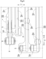
FIG. 7 is a transparent perspective view of the article transport vehicle: -
FIG. 8 is an enlarged perspective view of swing arms and support arms that are housed; -
FIG. 9 is an enlarged plan view of the swing arms and the support arms that are housed; -
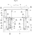
FIG. 10 is a plan view of the article transport vehicle viewed from an opening side in a state where a placement body is tilted; -
FIG. 11 is a cross-sectional view of the article transport vehicle taken along a plane orthogonal to an axis; -
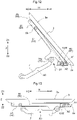
FIG. 12 is a diagram showing a relationship between the placement body in a first tilted state and a swing arm and a support arm; -
FIG. 13 is a diagram showing a relationship between the placement body in a non-tilted state and the swing arm and the support arm; -
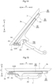
FIG. 14 is a diagram showing a relationship between the placement body in a second tilted state and a swing arm and a support arm; -
FIG. 15 is a diagram showing a relationship between the placement body in the non-tilted state and the swing arm and the support arm; and -
FIG. 16 is a diagram showing an example of a state where a vehicle body cover is removed from a vehicle body frame. - The following describes an embodiment of an article transport vehicle in a case where the article transport vehicle is provided in an article transport facility for sorting and transporting articles. First, the following describes an overview of an article transport facility F with reference to
FIGS. 1 to 5 . As shown inFIG. 1 , the article transport facility F includes a traveling surface Ff on which article transport vehicles V travel,article supply sections 109 for supplying transport target articles W to the article transport vehicles V, and receiving sections I for receiving articles W transported by the article transport vehicles V. The traveling surface Ff is formed as a spreading flat surface, and passages R along which the article transport vehicles V travel are set on the traveling surface Ff. The receiving sections I are provided at a plurality of positions on the traveling surface Ff. In the present embodiment, each of the receiving sections I provided at the plurality of positions includes a receiving opening Ia through which an article W is guided to a position below the traveling surface Ff. - As shown in
FIG. 2 , the article transport facility F includes a transport section T for transporting containers C for storing articles W, an emptycontainer supply section 108 for supplying containers C (empty containers Ce) not storing any article W, and ashipping section 107 for shipping containers C (filled containers Cf) storing at least one article W received from the article transport vehicles V via the receiving sections I (receiving openings Ia). As shown inFIGS. 3 to 5 , for example, the transport section T is arranged below the traveling surface Ff described above. In the present embodiment, the transport section T includes an empty container loading section T8 for receiving empty containers Ce supplied from the emptycontainer supply section 108, a filled container unloading section T7 for discharging filled containers Cf storing articles W received in the receiving sections I, and receiving/transporting sections Ti provided so as to connect the empty container loading section T8 and the filled container unloading section T7. In the present embodiment, the transport section T includes a plurality of receiving/transporting sections Ti, and each of the receiving/transporting sections Ti is provided so as to connect the empty container loading section T8 and the filled container unloading section T7. In this example, the plurality of receiving/transporting sections Ti are arranged side by side in parallel in a plan view. As shown inFIG. 5 , in the present embodiment, the empty container loading section T8, the filled container unloading section T7, and the receiving/transporting sections Ti are each constituted by a conveyor. - As shown in
FIGS. 3 to 5 , for example, the receiving sections I are arranged in such a manner as to be overlapped with the receiving/transporting sections Ti when viewed in the up-down direction. Containers C are arranged at positions corresponding to the receiving sections I in the receiving/transporting sections Ti. Accordingly, articles W received from the article transport vehicles V in the receiving sections I are guided through the receiving openings Ia to positions below the traveling surface Ff, and are then stored in containers C arranged in the receiving/transporting sections Ti (seeFIGS. 3 and4 , for example). In the present embodiment, a plurality of receiving sections I are arranged side by side with each other for each of the receiving/transporting sections Ti. Also, a container C is arranged at a position corresponding to each of the receiving sections I, or more specifically at a position directly under each of the receiving sections I. - Also, in the present embodiment, the article transport facility F includes shutters S (see
FIGS. 3 and4 ) for opening and closing the receiving openings Ia. Each shutter S keeps the corresponding receiving opening Ia closed until the receiving section I has received at least one article W that is to be sorted based on sorting information (seeFIG. 3 ). The shutter S then opens the receiving opening Ia after the receiving section I has received at least one article Wthat is to be sorted based on the sorting information (seeFIG. 4 ). Accordingly, the articles W sorted to the receiving sections I by the article transport vehicles V pass through the receiving openings Ia and are guided to positions below the traveling surface Ff, and are stored in containers C arranged in the receiving/transporting sections Ti. - In each of the
article supply sections 109, an article W for which a specified receiving section I has been designated as a transport destination based on the sorting information is supplied to an article transport vehicle V by a supply entity such as a worker or a robot, for example. The article transport vehicle V that received the article W in thearticle supply section 109 then travels along a passage R defined on the traveling surface Ff, and transports the article Wto the receiving section I that was designated based on the sorting information. - Each of the receiving sections I is provided with a position information holder (not shown) that holds position information indicating a position corresponding to the receiving section I. An article transport vehicle V travels toward a specified receiving section I that was designated as a transport destination, and when a position information detector (not shown) detects the position information held by the position information holder that corresponds to the specified receiving section I, the article transport vehicle V stops at that position (or transitions to a low-speed traveling state) and transfers an article W to that receiving section I. The position information holder is constituted by, for example, an indicator such as a barcode (e.g., a two-dimensional barcode) that indicates position information, a storage element such as an RFID tag (radio frequency identifier tag) that stores position information, or a signal transmitter such as a beacon that emits a signal indicating position information. For example, if the position information holder is a barcode, the position information detector is configured as a barcode reader, if the position information holder is an RFID tag, the position information detector is configured as an RFID reader, and if the position information holder is a beacon, the position information detector is configured as a signal receiver.
- In the present embodiment, the article transport facility F is configured by arranging a plurality of frame units 100 (see
FIG. 5 ) side by side in a grid pattern in a plan view as shown inFIGS. 1 and2 . Eachframe unit 100 includes the traveling surface Ff in which three receiving openings Ia are arranged on each of two sides of a passage R, and receiving/transporting sections Ti arranged in two rows in such a manner as to be overlapped with the traveling surface Ff (the receiving openings Ia) when viewed in the up-down direction. InFIG. 1 , one of the plurality offrame units 100 is denoted by the reference sign. - In the present embodiment, as shown in
FIGS. 1 and2 , 21 receiving sections I are provided for each receiving/transporting section Ti, and the empty container loading section T8 and the filled container unloading section T7 eachtransport 21 containers C synchronously as a container group. In this case, the receiving/transporting sections Ti each transport a group of 21 containers C after articles W have been stored in all of the 21 containers C included in that container group. - The following describes details of the article transport vehicles V with reference to
FIGS. 6 to 15 as well. As shown inFIGS. 3 and4 , each article transport vehicle V travels along a passage R defined on the traveling surface Ff (seeFIG. 1 ) with an article W placed on aplacement body 3 and transports the article W from anarticle supply section 109 to a receiving section I. Although described in detail later, the article transport vehicle V transfers the article W from theplacement body 3 to a receiving opening Ia by tilting theplacement body 3 beside the receiving opening Ia. - When directions are described with reference to the article transport vehicle V, a direction extending along a first axis A1, which is a swing axis about which the
placement body 3 is caused to swing to be tilted as described later, will be referred to as an axial direction L of the article transport vehicle V extending along a horizontal plane. When the article transport vehicle V travels along a traveling direction X, the axial direction L extends along the traveling direction X, and when the article transport vehicle V travels straight, the axial direction L matches the traveling direction X. Also, a direction orthogonal to the axial direction L in a plan view will be referred to as a vehicle body width direction H. In the state where the axial direction L matches the traveling direction X, the vehicle body width direction H matches a width direction Y. One side in the vehicle body width direction H will be referred to as a first side H1 in the vehicle body width direction, and the other side will be referred to as a second side H2 in the vehicle body width direction. - As shown in
FIG. 6 , for example, the article transport vehicle V includes acarriage body 10 that includes avehicle body frame 1 and avehicle body cover 2 and atransfer device 30 that is mounted on thecarriage body 10, and the article transport vehicle V transports an article W. The article transport vehicle V also includes a wheel 9 (seeFIGS. 6 and7 ) that is supported in such a manner as to be rotatable relative to thevehicle body frame 1 and a wheel drive source 90 (seeFIG. 7 ) that drives thewheel 9. Thewheel drive source 90 is an electric motor, for example, and operates by being supplied with power from a power storage body B (seeFIG. 16 ), such as a storage battery or a capacitor, mounted on the article transport vehicle V. As shown inFIGS. 6 and11 , for example, thetransfer device 30 includes theplacement body 3 that includes aplacement surface 3a on which an article W is placeable, acoupling mechanism 6 that couples theplacement body 3 and thecarriage body 10, and atransfer drive mechanism 4 that drives theplacement body 3 to transfer the article W. - In the present embodiment, the
placement body 3 is shaped as a tray with an edge portion of the plate-shapedplacement surface 3a protruding upward, and an article W is placed on the upper side of theplacement surface 3a. Thecarriage body 10 includes an opposingsurface 2a that faces alower surface 3b of theplacement body 3. Although described in detail later, theplacement body 3 provided above thecarriage body 10 is configured to swing relative to thecarriage body 10 about an axis extending along the axial direction L. That is, theplacement body 3 is configured to swing between a reference position at which theplacement body 3 extends along the opposingsurface 2a of thecarriage body 10 and a standing position at which theplacement body 3 is tilted relative to the opposingsurface 2a. Thetransfer drive mechanism 4 is a mechanism for changing an angle of theplacement surface 3a. - As shown in
FIG. 11 , thetransfer device 30 includes atransfer drive source 40 that is constituted by a motor or the like. In the present embodiment, thetransfer device 30 is configured to cause theplacement body 3 to swing relative to thecarriage body 10 about an axis (the first axis A1 or a third axis A3) extending along the axial direction L (the traveling direction X). As shown inFIG. 3 , thetransfer device 30 tilts theplacement body 3 in the vehicle body width direction H (the width direction Y) to cause the article W to slide in the width direction Y on theplacement body 3, and thus transfer the article W to a transfer location outward of the article transport vehicle V in the vehicle body width direction H (the width direction Y). - In the present embodiment, the
transfer device 30 is configured to cause theplacement body 3 to swing relative to thecarriage body 10 about the first axis A1 (seeFIGS. 12 and 13 ), as well as about the third axis A3 (seeFIGS. 14 and 15 ). That is, the article transport vehicle V is capable of transferring an article W to each of receiving sections I (transfer locations) respectively arranged on the first side H1 and the second side H2 in the vehicle body width direction (a first side Y1 and a second side Y2 in the width direction) relative to the article transport vehicle V by causing theplacement body 3 to swing. Note thatFIG. 3 shows a state in which articles W are transferred to a receiving section I that is on the first side Y1 in the width direction (the first side H1 in the vehicle body width direction) when viewed from the article transport vehicle V. - Also, in the present embodiment, a
first coupling mechanism 6A and asecond coupling mechanism 6B are provided as thecoupling mechanism 6, and a firsttransfer drive mechanism 4A and a secondtransfer drive mechanism 4B are provided as thetransfer drive mechanism 4. As shown inFIGS. 7 and8 , for example, thefirst coupling mechanism 6A couples theplacement body 3 and thecarriage body 10 in such a manner that theplacement body 3 is swingable relative to thecarriage body 10 about the first axis A1 extending along the horizontal plane. The firsttransfer drive mechanism 4A includes a first swing arm 51 (a swing arm 50) that swings about a second axis A2 parallel to the first axis A1 and a first transfer drive source 41 that causes thefirst swing arm 51 to swing. Thesecond coupling mechanism 6B couples theplacement body 3 and thecarriage body 10 in such a manner that theplacement body 3 is swingable relative to thecarriage body 10 about the third axis A3 extending along the horizontal plane. The secondtransfer drive mechanism 4B includes a second swing arm 52 (a swing arm 50) that swings about a fourth axis A4 parallel to the third axis A3 and a second transfer drive source 42 that causes thesecond swing arm 52 to swing. Note that the third axis A3 is parallel to the first axis A1, and the first axis A1, the second axis A2, the third axis A3, and the fourth axis A4 are parallel to each other. - In the present embodiment, a configuration is described as an example in which the first axis A1 and the second axis A2 are separate axes, but the first axis A1 and the second axis A2 may be the same axis. Likewise, a configuration is described as an example in which the third axis A3 and the fourth axis A4 are separate axes, but the third axis A3 and the fourth axis A4 may be the same axis. Also, in the present embodiment, the common transfer drive source 40 (a motor) serves as the first transfer drive source 41 and the second transfer drive source 42 as described later. Also, an
output member 7 that is coupled to anoutput shaft 47 of thetransfer drive source 40 is common to the first transfer drive source 41 and the second transfer drive source 42. Theoutput member 7 is also included in thetransfer drive mechanism 4. - Each
swing arm 50 is formed in such a manner as to extend along the vehicle body width direction H and swings between a reference position (seeFIGS. 13 and15 ) at which theswing arm 50 extends along the opposingsurface 2a and a standing position (seeFIGS. 12 and14 ) at which theswing arm 50 is tilted relative to the opposingsurface 2a. When theswing arm 50 is at the reference position, theplacement body 3 is at a horizontal position at which theplacement surface 3a extends along the horizontal plane as shown inFIGS. 13 and15 , for example. As shown inFIGS. 12 and14 , for example, while theswing arm 50 moves from the horizontal position to the standing position, theplacement body 3 swings due to being pressed by theswing arm 50 from a lower side, and when theswing arm 50 is at the standing position, theplacement body 3 is at a tilted position at which theplacement surface 3a is tilted relative to the horizontal plane. - Specifically, the
first swing arm 51 is formed in such a manner as to extend along a direction (the vehicle body width direction H) orthogonal to the second axis A2 and swings between the reference position (seeFIGS. 7 ,8 ,11 , and13 , for example) at which thefirst swing arm 51 extends along the opposingsurface 2a and the standing position (seeFIGS. 10 and12 , for example) at which thefirst swing arm 51 is tilted relative to the opposingsurface 2a. When thefirst swing arm 51 is at the reference position, theplacement body 3 is at the horizontal position (seeFIGS. 6 ,11 , and13 , for example) at which theplacement surface 3a extends along the horizontal plane. While thefirst swing arm 51 moves from the horizontal position to the standing position, theplacement body 3 swings due to being pressed by thefirst swing arm 51 from the lower side Z2, and when thefirst swing arm 51 is at the standing position, theplacement body 3 is at the tilted position (a first tilted position, seeFIGS. 10 and12 ) at which theplacement surface 3a is tilted relative to the horizontal plane. At the first tilted position, theplacement surface 3a is tilted in such a manner as to face the first side H1 in the vehicle body width direction. - Also, the
second swing arm 52 is formed in such a manner as to extend along a direction (the vehicle body width direction H) orthogonal to the fourth axis A4 and swings between the reference position (seeFIGS. 7 ,8 ,11 , and15 , for example) at which thesecond swing arm 52 extends along the opposingsurface 2a and the standing position (seeFIG. 14 , for example) at which thesecond swing arm 52 is tilted relative to the opposingsurface 2a. When thesecond swing arm 52 is at the reference position, theplacement body 3 is at the horizontal position (seeFIGS. 6 ,11 , and15 , for example) at which theplacement surface 3a extends along the horizontal plane. While thesecond swing arm 52 moves from the horizontal position to the standing position, theplacement body 3 swings due to being pressed by thesecond swing arm 52 from the lower side Z2, and when thesecond swing arm 52 is at the standing position, theplacement body 3 is at the tilted position (a second tilted position, seeFIG. 14 ) at which theplacement surface 3a is tilted relative to the horizontal plane. At the second tilted position, theplacement surface 3a is tilted in such a manner as to face the second side H2 in the vehicle body width direction. - In the present embodiment, as shown in
FIGS. 7 and10 , for example, theswing arms 50 for tilting theplacement surface 3a in respective directions are each disposed at a position in the axial direction L. That is, the singlefirst swing arm 51 for tilting theplacement surface 3a to the first tilted position is disposed at a position in the axial direction L, and the singlesecond swing arm 52 for tilting theplacement surface 3a to the second tilted position is disposed at a position in the axial direction L. Also, thefirst swing arm 51 and thesecond swing arm 52 are disposed adjacent to each other in the axial direction L. - If the
placement surface 3a is tilted by asingle swing arm 50, theplacement surface 3a may wobble or warp, for example. Therefore, the present embodiment includessupport arms 60, which will be described later, extending in parallel to theswing arms 50 to assist a positional change of theplacement body 3 caused by theswing arms 50 and keep the placement body 3 (theplacement surface 3a) from warping. Thetransfer device 30 includes thecoupling mechanism 6 that couples theplacement body 3 and thecarriage body 10, and thesupport arms 60 constitute a part of thecoupling mechanism 6. In the present embodiment, thefirst coupling mechanism 6A and thesecond coupling mechanism 6B are provided as thecoupling mechanism 6. - As shown in
FIGS. 7 and8 , for example, thefirst coupling mechanism 6A couples theplacement body 3 and the carriage body 10 (the vehicle body cover 2) in such a manner that theplacement body 3 is swingable relative to thecarriage body 10 about the first axis A1 extending along the horizontal plane. Thefirst coupling mechanism 6A includes a first support arm 61 (a support arm 60) that swings about the first axis A1 and a first fulcrum support portion 63 (a fulcrum support portion 67) that supports a swing fulcrum of thefirst support arm 61. Thefirst support arm 61 is swingably coupled to theplacement body 3 at a first coupling portion 65 (a coupling portion 69) that is set in an end portion of thefirst support arm 61 opposite to the firstfulcrum support portion 63. - Specifically, the
first support arm 61 is formed in such a manner as to extend along a direction (the vehicle body width direction H) orthogonal to the first axis A1 and swings between a support reference position (a first support reference position: seeFIGS. 7 ,8 , and13 , for example) at which thefirst support arm 61 extends along the opposingsurface 2a and a support standing position (a first support standing position: seeFIGS. 10 and12 ) at which thefirst support arm 61 is tilted relative to the opposingsurface 2a. When theplacement body 3 is caused to swing by thefirst swing arm 51, thefirst support arm 61 swings together with theplacement body 3 to the support standing position (the first support standing position). At this time, thefirst support arm 61 swings relative to the vehicle body cover 2 (the carriage body 10) at the firstfulcrum support portion 63 coupled to thecarriage body 10. At thefirst coupling portion 65 coupled to theplacement body 3, thefirst support arm 61 changes its position together with theplacement body 3 without swinging. - When the
placement body 3 is caused to swing by thesecond swing arm 52, thefirst support arm 61 does not swing together with theplacement body 3 and remains at the support reference position (the first support reference position). That is, thefirst support arm 61 does not swing relative to the vehicle body cover 2 (the carriage body 10) at the firstfulcrum support portion 63 coupled to thecarriage body 10. On the other hand, at thefirst coupling portion 65 coupled to theplacement body 3, thefirst support arm 61 swings relative to theplacement body 3 because theplacement body 3 swings. That is, theplacement body 3 and thefirst support arm 61 swing relative to each other at thefirst coupling portion 65, and thus thefirst support arm 61 remains at the first support reference position. - Also, as shown in
FIGS. 7 and8 , for example, thesecond coupling mechanism 6B couples theplacement body 3 and thecarriage body 10 in such a manner that theplacement body 3 is swingable relative to thecarriage body 10 about the third axis A3 extending along the horizontal plane. Thesecond coupling mechanism 6B includes a second support arm 62 (a support arm 60) that swings about the third axis A3 and a second fulcrum support portion 64 (a fulcrum support portion 67) that supports a swing fulcrum of thesecond support arm 62. Thesecond support arm 62 is swingably coupled to theplacement body 3 at a second coupling portion 66 (a coupling portion 69) that is set in an end portion of thesecond support arm 62 opposite to the secondfulcrum support portion 64. - Specifically, the
second support arm 62 is formed in such a manner as to extend along a direction (the vehicle body width direction H) orthogonal to the third axis A3 and swings between a support reference position (a second support reference position: seeFIGS. 7 ,8 , and15 , for example) at which thesecond support arm 62 extends along the opposingsurface 2a and a support standing position (a second support standing position: seeFIG. 14 ) at which thesecond support arm 62 is tilted relative to the opposingsurface 2a. When theplacement body 3 is caused to swing by thesecond swing arm 52, thesecond support arm 62 swings together with theplacement body 3 to the support standing position (the second support standing position). At this time, thesecond support arm 62 swings relative to the vehicle body cover 2 (the carriage body 10) at the secondfulcrum support portion 64 coupled to thecarriage body 10. At thesecond coupling portion 66 coupled to theplacement body 3, thesecond support arm 62 changes its position together with theplacement body 3 without swinging. - When the
placement body 3 is caused to swing by thefirst swing arm 51, thesecond support arm 62 does not swing together with theplacement body 3 and remains at the support reference position (the second support reference position). That is, thesecond support arm 62 does not swing relative to the vehicle body cover 2 (the carriage body 10) at the secondfulcrum support portion 64 coupled to thecarriage body 10. On the other hand, at thesecond coupling portion 66 coupled to theplacement body 3, thesecond support arm 62 swings relative to theplacement body 3 because theplacement body 3 swings. That is, theplacement body 3 and thesecond support arm 62 swing relative to each other at thesecond coupling portion 66, and thus thesecond support arm 62 remains at the second support reference position. - As shown in
FIG. 11 , thetransfer drive mechanism 4 includes thetransfer drive source 40 and atransmission mechanism 5 for transmitting driving force from thetransfer drive source 40 to theplacement body 3. Thetransmission mechanism 5 includes theswing arms 50 and theoutput member 7 that is coupled to thetransfer drive source 40. Theoutput member 7 transmits driving force from thetransfer drive source 40 to theswing arms 50, and the driving force is transmitted to theplacement body 3 via theswing arms 50. Theswing arms 50 constituting thetransmission mechanism 5 can be said to be driven members that are driven by theoutput member 7. - As shown in
FIG. 11 , in the present embodiment, thetransmission mechanism 5 includes theoutput member 7 that is coupled to theoutput shaft 47 of thetransfer drive source 40 and is shaped as a lever that swings about a rotation axis (an output axis AO) of theoutput shaft 47. Theswing arms 50 are driven by theoutput member 7. Pressingrollers 75 that come into contact with theswing arms 50 and cause theswing arms 50 to swing are provided in two end portions of theoutput member 7 in the vehicle body width direction H. Eachswing arm 50 includes acam portion 57 protruding toward the lower side Z2, and thepressing rollers 75 respectively come into contact with thecam portions 57. Theswing arms 50 are not coupled to theoutput member 7 and are configured to operate by being pressed by theoutput member 7. As a result of thepressing rollers 75 pressing theswing arms 50 along thecam portions 57, theswing arms 50 swing about the output axis AO. - For example, when the
output member 7 is caused to swing in a first swing direction D1 shown inFIG. 11 by thetransfer drive source 40, the pressing roller 75 (a firstpressing roller 75a) disposed on the second side H2 in the vehicle body width direction comes into contact with thecam portion 57 of thefirst swing arm 51 and presses thecam portion 57 to change the position of thefirst swing arm 51 from the reference position (seeFIGS. 11 and13 ) to the standing position (FIG. 12 ). Likewise, when theoutput member 7 is caused to swing in a second swing direction D2 shown inFIG. 11 by thetransfer drive source 40, the pressing roller 75 (a secondpressing roller 75b) disposed on the first side H1 in the vehicle body width direction comes into contact with thecam portion 57 of thesecond swing arm 52 and presses thecam portion 57 to change the position of thesecond swing arm 52 from the reference position (seeFIGS. 11 and15 ) to the standing position (FIG. 14 ). Theplacement body 3 changes its position between the horizontal position and the tilted positions in conjunction with theswing arms 50, which serve as driven members. - As described above, the present embodiment includes the
support arms 60 provided in parallel to theswing arms 50 to assist a positional change of theplacement body 3 caused by theswing arms 50 and keep the placement body 3 (theplacement surface 3a) from warping. In the present embodiment, twosupport arms 60 are disposed so as to sandwich thefirst swing arm 51 in the axial direction L to support theplacement body 3 when the position of theplacement surface 3a is changed to the first tilted position by thefirst swing arm 51. That is, thefirst swing arm 51 is disposed between twofirst support arms 61 in the axial direction L. Likewise, twosupport arms 60 are disposed so as to sandwich thesecond swing arm 52 in the axial direction L to support theplacement body 3 when the position of theplacement surface 3a is changed to the second tilted position by thesecond swing arm 52. That is, thesecond swing arm 52 is disposed between twosecond support arms 62 in the axial direction L. As described above, twosupport arms 60 are provided for eachswing arm 50, and therefore, it is possible to keep the placement body 3 (theplacement surface 3a) from warping when the position of theplacement body 3 is changed by theswing arm 50. - As shown in
FIGS. 8 and9 , recessedgrooves 25 for housing theswing arms 50 and thesupport arms 60 are formed in the opposingsurface 2a of thevehicle body cover 2. When a recessedgroove 25 for housing theswing arms 50 and a recessedgroove 25 for housing thesupport arms 60 are distinguished from each other, the recessedgroove 25 for housing theswing arms 50 will be referred to as a swingarm housing groove 255, and the recessedgroove 25 for housing thesupport arms 60 will be referred to as a supportarm housing groove 256. - Each
swing arm 50 is swingably supported by the vehicle body cover 2 (the carriage body 10) at aswing support portion 54 on one end side in the vehicle body width direction H. The other end of theswing arm 50 is a free end that is provided with acontact roller 53. Thecontact roller 53 moves in the vehicle body width direction H while being in contact with thelower surface 3b of theplacement body 3, and thus changes the position of theplacement surface 3a of theplacement body 3 from the horizontal position to the tilted position. Also, theswing arm 50 changes its position by being pressed by theoutput member 7 as described above. Accordingly, the swingarm housing groove 255 is open to allow theoutput member 7 to move past the opposingsurface 2a toward the upper side Z1. That is, the swingarm housing groove 255 is formed as anopening 27, and it can be said that thevehicle body cover 2 includes theopening 27 through which theoutput member 7 passes in the up-down direction Z. - One end of each
support arm 60 in the vehicle body width direction H is swingably supported by thevehicle body cover 2, and the other end of thesupport arm 60 in the vehicle body width direction H is swingably supported by thelower surface 3b of theplacement body 3. In other words, theplacement body 3 is attached to thevehicle body cover 2 via thesupport arm 60 in such a manner as to be swingable relative to thevehicle body cover 2. Unlike the swingarm housing groove 255, the supportarm housing groove 256 is shaped as a groove and does not extend through thevehicle body cover 2 in the up-down direction Z. - As described above, the
placement body 3, the swing arms 50 (the driven members), and thesupport arms 60 are supported by thevehicle body cover 2. Thewheel drive source 90, thetransfer drive source 40, and theoutput member 7 are supported by thevehicle body frame 1. As shown inFIGS. 7 and11 , for example, thevehicle body cover 2 covers thewheel drive source 90 and thetransfer drive source 40. As described above, theswing arms 50 driven by theoutput member 7 are not coupled to theoutput member 7 and are configured to operate by being pressed by theoutput member 7. Accordingly, thevehicle body cover 2 is attached to thevehicle body frame 1 in such a manner as to be attachable to and detachable from thevehicle body frame 1 while supporting theplacement body 3, theswing arms 50, and thesupport arms 60. -
FIG. 16 shows an example of a state where thevehicle body cover 2 is removed from thevehicle body frame 1. In addition to thevehicle body frame 1, theswing arms 50 and thesupport arms 60 are also shown using imaginary lines to clarify the relationship between theswing arms 50 and theoutput member 7 and the relationship between theswing arms 50 and thesupport arms 60. Theswing arms 50 are removed from thevehicle body frame 1 together with thevehicle body cover 2, and therefore, theoutput member 7 is exposed and maintenance of theoutput member 7 can be easily performed. For example, thepressing rollers 75 can be easily replaced when worn out. Also, in the present embodiment, thetransfer drive source 40 is disposed on the lower side Z2 of thesupport arms 60, but thesupport arms 60 are removed from thevehicle body frame 1 together with thevehicle body cover 2, and therefore, thetransfer drive source 40 is exposed and maintenance of thetransfer drive source 40 can be easily performed. - Also, in the present embodiment, the power storage body B is disposed on the lower side Z2 of the
support arms 60 as shown inFIG. 16 . It is known that the power storage capability of the power storage body B such as a storage battery or a capacitor degrades over time. When the power storage capability has degraded to be lower than or equal to a prescribed level, the power storage body B is replaced. In the present embodiment, thesupport arms 60 are removed from thevehicle body frame 1 together with thevehicle body cover 2, and therefore, the power storage body B is exposed and can be easily replaced. - As shown in
FIGS. 6 and7 , thevehicle body cover 2 includes atop surface portion 21 that faces thelower surface 3b of theplacement body 3 and covers thewheel drive source 90 and thetransfer drive source 40 from the upper side, and aside wall portion 23 that extends from an outer edge portion of thetop surface portion 21 toward the lower side. Alower end 23t of theside wall portion 23 is on the lower side Z2 of anupper end 9t of thewheel 9. That is, theside wall portion 23 covers a side surface of thewheel 9. In the state where thevehicle body cover 2 is attached to thevehicle body frame 1, most of the members constituting the article transport vehicle V including a portion of thewheel 9 are covered by thevehicle body cover 2. Therefore, it is possible to appropriately protect the article transport vehicle V from foreign matter including dust, which would otherwise enter the inside of the article transport vehicle V. On the other hand, when it is necessary to perform maintenance of thewheel 9, thewheel drive source 90, thetransfer drive source 40, theoutput member 7, or the like, thevehicle body cover 2 can be easily removed and therefore, the maintenance is facilitated. - Also, the article transport vehicle V is configured to be capable of being stopped when there is an abnormality in the article transport facility F or the individual article transport vehicle V, for example. In the present embodiment, the article transport vehicle V includes a stop switch SW for stopping the
wheel drive source 90 and thetransfer drive source 40 as shown inFIGS. 7 and8 , for example. The stop switch SW is supported by thevehicle body frame 1, and thevehicle body cover 2 includes a stop switch opening 29 formed at a position corresponding to the stop switch SW. - Such a stop switch SW is often electrically connected to the
wheel drive source 90 and thetransfer drive source 40 or a control device (not shown) for controlling thewheel drive source 90 and thetransfer drive source 40 via connecting wires. Accordingly, if the stop switch SW is supported by thevehicle body cover 2, thevehicle body cover 2 cannot be removed from thevehicle body frame 1 unless the connecting wires are removed. If the stop switch SW is supported by thevehicle body frame 1 as in the present embodiment, there is no need to remove the connecting wires when removing the vehicle body cover 2 from thevehicle body frame 1. Also, thevehicle body cover 2 includes thestop switch opening 29, and therefore, the stop switch SW can be easily operated from the outside even if the stop switch SW is supported by thevehicle body frame 1. - Also, the article transport vehicle V includes a display lamp LP that serves as an indicator that indicates a state of a section of the article transport vehicle V, such as a driving state of the
wheel drive source 90, a driving state of thetransfer drive source 40, the position of theplacement body 3, and a charge amount of the power storage body B (a storage battery, a capacitor, etc.). The present embodiment includes a plurality of display lamps LP, and a display lamp substrate LPA on which the display lamps LP are mounted is supported by thevehicle body frame 1. Thevehicle body cover 2 attached to thevehicle body frame 1 covers the display lamps LP, but thevehicle body cover 2 includeslight transmitting sections 28 that are provided at positions corresponding to the display lamps LP and transmit light from the display lamps LP outward from thevehicle body cover 2. Due to thelight transmitting sections 28 being provided, it is possible to support the display lamps LP on thevehicle body frame 1 and attach thevehicle body cover 2 to thevehicle body frame 1 in such a manner as to cover the display lamps LP. - A control circuit and a power source (both not shown) for the display lamps LP are often supported by the
vehicle body frame 1, and the display lamps LP are often connected to the power source via connecting wires. Accordingly, if the display lamps LP are supported by thevehicle body cover 2, thevehicle body cover 2 cannot be removed from thevehicle body frame 1 unless the connecting wires are removed. If the display lamps LP are supported by thevehicle body frame 1 as in the present embodiment, there is no need to remove the connecting wires when removing the vehicle body cover 2 from thevehicle body frame 1. Also, thevehicle body cover 2 includes thelight transmitting sections 28, and therefore, lighting states of the display lamps LP can be easily checked from the outside even if the display lamps LP are supported by thevehicle body frame 1. - Incidentally, the
swing arms 50 may wobble when changing their positions from the reference position to the standing position to lift theplacement body 3. If theswing arms 50 wobble and consequently theplacement body 3 wobbles, an article W supported by theplacement body 3 may fall before sliding down to a transfer destination or durability of theswing arms 50 may be reduced. Therefore, in the present embodiment, the opposingsurface 2a is provided withguide members 8 for guiding swinging movement of theswing arms 50 as shown inFIGS. 8 ,9 , and10 , for example. - The
guide members 8 are detachably attached to thecarriage body 10, and can be replaced easily when worn out due to sliding movement of theswing arms 50 against theguide members 8 or friction between theguide members 8 and theswing arms 50, for example. In the present embodiment, theguide members 8 are fitted into the swingarm housing groove 255 described above. In the present embodiment, eachguide member 8 is shaped as a groove that is open on the upper side Z1. As described above, the swingarm housing groove 255 is also shaped as a groove, and theguide members 8 are fixed by being fitted into the swingarm housing groove 255. - As described above, in the present embodiment, the
first swing arm 51 and thesecond swing arm 52 are provided as theswing arms 50. Thefirst swing arm 51 is provided with afirst guide member 81 that guides swinging movement of thefirst swing arm 51, and thesecond swing arm 52 is provided with asecond guide member 82 that guides swinging movement of thesecond swing arm 52. - In the present embodiment, the
support arms 60 are also provided to stably tilt theplacement body 3 as described above. Thesupport arms 60 also swing similarly to theswing arms 50, and accordingly, as is the case with theswing arms 50,support guide members 80 for guiding swinging movement of thesupport arms 60 are provided in the opposingsurface 2a. - Similarly to the
guide members 8, thesupport guide members 80 are detachably attached to thecarriage body 10. Thesupport guide members 80 can be replaced easily when worn out due to friction between thesupport guide members 80 and thesupport arms 60, for example. In the present embodiment, thesupport guide members 80 are fitted into the supportarm housing groove 256 described above. In the present embodiment, eachsupport guide member 80 is shaped as a groove that is open on the upper side Z1 similarly to theguide members 8. As described above, the supportarm housing groove 256 is also shaped as a groove, and thesupport guide members 80 are fixed by being fitted into the supportarm housing groove 256. - In the present embodiment, the
first support arm 61 and thesecond support arm 62 are provided as thesupport arms 60. Thefirst support arm 61 is provided with a firstsupport guide member 83 that guides swinging movement of thefirst support arm 61, and thesecond support arm 62 is provided with a secondsupport guide member 84 that guides swinging movement of thesecond support arm 62. - As described above, according to the present embodiment, it is possible to provide an article transport vehicle V that makes it possible to easily perform maintenance of drive sources of the
wheel 9 and the transfer device 30 (thewheel drive source 90 and the transfer drive source 40), thetransfer drive mechanism 4, and the like. - The following describes other embodiments. Configurations of the following embodiments are not only applicable individually but also applicable in combination with configurations of other embodiments as long as no contradiction arises.
- (1) In the above embodiment, an example is described in which the
coupling mechanism 6 includes thefirst coupling mechanism 6A and thesecond coupling mechanism 6B, thetransfer drive mechanism 4 includes the firsttransfer drive mechanism 4A and the secondtransfer drive mechanism 4B, and articles W can be transferred to both sides in the vehicle body width direction H (the width direction Y). However, a configuration is also possible in which thecoupling mechanism 6 includes only either thefirst coupling mechanism 6A or thesecond coupling mechanism 6B (e.g., only thefirst coupling mechanism 6A), and thetransfer drive mechanism 4 includes only either the firsttransfer drive mechanism 4A or the secondtransfer drive mechanism 4B (e.g., only the firsttransfer drive mechanism 4A). In this case as well, if the article transport vehicle V travels in both directions along the traveling direction X (i.e., travels by turning 180 degrees) with the front side of the article transport vehicle V fixed, it is possible to transfer articles W to both sides in the width direction Y relative to the article transport vehicle V even if the article transport vehicle V is configured to be capable of transferring articles Wto only one side in the vehicle body width direction H. - (2) In the above embodiment, an example is described in which the
support arms 60 are provided. However, a configuration is also possible in which thesupport arms 60 are not provided and only theswing arms 50 are provided. - (3) In the above embodiment, an example is described in which the
vehicle body cover 2 includes theopening 27 through which theoutput member 7, which is a lever member, passes in the up-down direction Z. However, theopening 27 may also be formed in such a manner that theswing arms 50, which are driven members, pass through theopening 27 in the up-down direction Z. In any case, rather than the configuration in which the opposingsurface 2a includes such anopening 27, a configuration may be adopted in which the entire opposingsurface 2a is open excluding theswing support portions 54 supporting theswing arms 50 and the like. - (4) In the above embodiment, an example is described in which the article transport vehicle V includes the stop switch SW and the display lamps LP. However, a configuration is also possible in which the article transport vehicle V does not include the stop switch SW and the display lamps LP.
- The following briefly describes a summary of the article transport vehicle described above.
- In an aspect, an article transport vehicle is configured to transport an article and includes: a vehicle body frame; a vehicle body cover; a wheel supported in such a manner as to be rotatable relative to the vehicle body frame; a wheel drive source configured to drive the wheel; a placement body including a placement surface on which the article is placeable; and a transfer drive mechanism configured to drive the placement body to transfer the article, wherein the transfer drive mechanism includes: a transfer drive source; and a transmission mechanism configured to transmit driving force from the transfer drive source to the placement body, the transmission mechanism includes: an output member coupled to an output shaft of the transfer drive source; and a driven member configured to be driven by the output member, the placement body moves in conjunction with the driven member, the driven member is not coupled to the output member and is configured to operate by being pressed by the output member, the wheel drive source, the transfer drive source, and the output member are supported by the vehicle body frame, the placement body and the driven member are supported by the vehicle body cover, and the vehicle body cover covers the wheel drive source and the transfer drive source and is detachably attached to the vehicle body frame.
- According to this configuration, the placement body and the driven member are supported by the vehicle body cover, and the wheel drive source, the transfer drive source, and the output member are supported by the vehicle body frame. Also, the driven member that operates by being pressed by the output member is not coupled to the output member. That is, the vehicle body cover is attached to the vehicle body frame in such a manner as to be attachable to and detachable from the vehicle body frame while supporting the placement body and the driven member. The vehicle body cover covers the wheel drive source and the transfer drive source, and accordingly, when the vehicle body cover is removed from the vehicle body frame, maintenance of the wheel drive source and the transfer drive source can be easily performed. Also, the output member is coupled to the output shaft of the transfer drive source, and accordingly, maintenance of the output member can be easily performed as well. As described above, according to this configuration, it is possible to provide an article transport vehicle that makes it possible to easily perform maintenance of the drive sources of the wheel and the placement body, the transfer drive mechanism, and the like.
- Here, it is preferable that the output member is a lever member configured to swing about a rotation axis of the output shaft, and the vehicle body cover includes an opening through which the output member passes in an up-down direction.
- According to this configuration, even if the transfer drive source and the output member are housed in the state of being covered by the vehicle body cover, the output member passes through the opening in the up-down direction when swinging, and therefore, the output member can appropriately drive the driven member. Moreover, when the opening is provided, it is possible to appropriately remove the vehicle body cover from the vehicle body frame together with the driven member while leaving the output member on the vehicle body frame. Also, the opening makes it easy to position the driven member relative to the vehicle body frame supporting the output member when the vehicle body cover is attached to the vehicle body frame.
- It is preferable that the vehicle body cover includes: a top surface portion facing a lower surface of the placement body and covering the wheel drive source and the transfer drive source from an upper side; and a side wall portion extending from an outer edge portion of the top surface portion toward a lower side, and a lower end of the side wall portion is on the lower side of an upper end of the wheel.
- According to this configuration, the side wall portion covers a side surface of the wheel, and most of the members constituting the article transport vehicle including a portion of the wheel are covered by the vehicle body cover when the vehicle body cover is attached to the vehicle body frame. Therefore, it is possible to appropriately protect the article transport vehicle from foreign matter including dust, which would otherwise enter the inside of the article transport vehicle. On the other hand, when it is necessary to perform maintenance of the wheel, the wheel drive source, the transfer drive source, the output member, or the like, the vehicle body cover can be removed and these members can be exposed, and therefore, the maintenance is facilitated.
- It is preferable that the article transport vehicle further includes a stop switch configured to stop the wheel drive source and the transfer drive source, wherein the stop switch is supported by the vehicle body frame, and the vehicle body cover includes a stop switch opening at a position corresponding to the stop switch.
- Such a stop switch is often electrically connected to the wheel drive source and the transfer drive source or a control device for controlling the wheel drive source and the transfer drive source via connecting wires. Accordingly, if the stop switch is supported by the vehicle body cover, the vehicle body cover cannot be removed from the vehicle body frame unless the connecting wires are removed. If the stop switch is supported by the vehicle body frame as in this configuration, there is no need to remove the connecting wires when removing the vehicle body cover from the vehicle body frame. Also, the vehicle body cover includes the stop switch opening, and therefore, the stop switch can be easily operated from the outside even if the stop switch is supported by the vehicle body frame.
- It is preferable that the article transport vehicle further includes a display lamp configured to indicate a state of a section, wherein the display lamp is supported by the vehicle body frame, and the vehicle body cover includes a light transmitting section that is provided at a position corresponding to the display lamp and configured to transmit light from the display lamp outward from the vehicle body cover.
- A control circuit and a power source for the display lamp are often supported by the vehicle body frame, and the display lamp is often connected to the power source via a connecting wire. Accordingly, if the display lamp is supported by the vehicle body cover, the vehicle body cover cannot be removed from the vehicle body frame unless the connecting wire is removed. If the display lamp is supported by the vehicle body frame as in the present embodiment, there is no need to remove the connecting wire when removing the vehicle body cover from the vehicle body frame. Also, the vehicle body cover includes the light transmitting section, and therefore, a lighting state of the display lamp can be easily checked from the outside even if the display lamp is supported by the vehicle body frame.
- It is preferable that the placement body is swingably supported by the vehicle body cover in such a manner as to be swingable about a first axis extending along a horizontal plane, the output member is a lever member configured to swing about a rotation axis of the output shaft that is parallel to the first axis, the driven member is a swing arm configured to swing about a second axis that is parallel to the first axis, the swing arm swings between a reference position at which the swing arm extends along the horizontal plane and a standing position at which the swing arm is tilted relative to the horizontal plane, and when the swing arm is at the reference position, the placement body is at a horizontal position at which the placement surface extends along the horizontal plane, while the swing arm moves from the horizontal position to the standing position, the placement body swings about the first axis due to being pressed by the swing arm from a lower side, and when the swing arm is at the standing position, the placement body is at a tilted position at which the placement surface is tilted relative to the horizontal plane.
- According to this configuration, the article transport vehicle can transfer an article from the article transport vehicle to a transfer target location by changing the position of the placement surface, on which the article is placed at the horizontal position, to the tilted position to cause the article to slide. The placement body including the placement surface and the driven member (the swing arm) that tilts the placement body to change the position of the placement surface to the tilted position are supported by the vehicle body cover, and the output member that drives the driven member (the swing arm) and the transfer drive source are supported by the vehicle body frame. In the article transport vehicle having a relatively complex mechanism as described above, the placement body and the driven member (the swing arm) can be removed from the vehicle body frame together with the vehicle body cover, and thus it is possible to obtain a structure that facilitates maintenance of the output member and the transfer drive source.
-
- 1
- Vehicle body frame
- 2
- Vehicle body cover
- 3
- Placement body
- 3a
- Placement surface
- 3b
- Lower surface
- 4
- Transfer drive mechanism
- 5
- Transmission mechanism
- 7
- Output member
- 9
- Wheel
- 9t
- Upper end (upper end of wheel)
- 21
- Top surface portion
- 23
- Side wall portion
- 23t
- Lower end (lower end of side wall portion)
- 27
- Opening
- 28
- Light transmitting section
- 29
- Stop switch opening
- 40
- Transfer drive source
- 47
- Output shaft
- 50
- Swing arm (driven member)
- 90
- Wheel drive source
- A0
- Output axis (rotation axis of output shaft)
- A1
- First axis
- A2
- Second axis
- LP
- Display lamp
- SW
- Stop switch
- V
- Article transport vehicle
- W
- Article
- Z
- Up-down direction
- Z1
- Upper side
- Z2
- Lower side
Claims (6)
- An article transport vehicle (V) configured to transport an article (W), comprising:a vehicle body frame (1);a vehicle body cover (2);a wheel (9) supported in such a manner as to be rotatable relative to the vehicle body frame (1); a wheel drive source (90) configured to drive the wheel (9);a placement body (3) including a placement surface (3a) on which the article (W) is placeable; anda transfer drive mechanism (4) configured to drive the placement body (3) to transfer the article (W),characterized in that,the transfer drive mechanism (4) includes:a transfer drive source (40); anda transmission mechanism (5) configured to transmit driving force from the transfer drive source (40) to the placement body (3),the transmission mechanism (5) includes:an output member (7) coupled to an output shaft (47) of the transfer drive source (40); anda driven member (50) configured to be driven by the output member (7),the placement body (3) moves in conjunction with the driven member (50),the driven member (50) is not coupled to the output member (7) and is configured to operate by being pressed by the output member (7),the wheel drive source (90), the transfer drive source (40), and the output member (7) are supported by the vehicle body frame (1),the placement body (3) and the driven member (50) are supported by the vehicle body cover (2), andthe vehicle body cover (2) covers the wheel drive source (90) and the transfer drive source (40) and is detachably attached to the vehicle body frame (1).
- The article transport vehicle (V) according to claim 1,wherein the output member (7) is a lever member configured to swing about a rotation axis (A0) of the output shaft (47), andthe vehicle body cover (2) includes an opening (27) through which the output member (7) passes in an up-down direction (Z).
- The article transport vehicle (V) according to claim 1 or 2,
wherein the vehicle body cover (2) includes:a top surface portion (21) facing a lower surface (3b) of the placement body (3) and covering the wheel drive source (90) and the transfer drive source (40) from an upper side (Z1); anda side wall portion (23) extending from an outer edge portion of the top surface portion (21) toward a lower side (Z2), anda lower end (23t) of the side wall portion (23) is on the lower side (Z2) of an upper end (9t) of the wheel (9). - The article transport vehicle (V) according to any one of claims 1 to 3, further comprisinga stop switch (SW) configured to stop the wheel drive source (90) and the transfer drive source (40),wherein the stop switch (SW) is supported by the vehicle body frame (1), andthe vehicle body cover (2) includes a stop switch opening (29) at a position corresponding to the stop switch (SW).
- The article transport vehicle (V) according to any one of claims 1 to 4, further comprisinga display lamp (LP) configured to indicate a state of a section,wherein the display lamp (LP) is supported by the vehicle body frame (1), andthe vehicle body cover (2) includes a light transmitting section (28) that is provided at a position corresponding to the display lamp (LP) and configured to transmit light from the display lamp (LP) outward from the vehicle body cover (2).
- The article transport vehicle (V) according to any one of claims 1 to 5,wherein the placement body (3) is swingably supported by the vehicle body cover (2) in such a manner as to be swingable about a first axis (A1) extending along a horizontal plane,the output member (7) is a lever member configured to swing about a rotation axis (A0) of the output shaft (47) that is parallel to the first axis (A1),the driven member (50) is a swing arm (50) configured to swing about a second axis (A2) that is parallel to the first axis (A1),the swing arm (50) swings between a reference position at which the swing arm (50) extends along the horizontal plane and a standing position at which the swing arm (50) is tilted relative to the horizontal plane, andwhen the swing arm (50) is at the reference position, the placement body (3) is at a horizontal position at which the placement surface (3a) extends along the horizontal plane, while the swing arm (50) moves from the horizontal position to the standing position, the placement body (3) swings about the first axis (A1) due to being pressed by the swing arm (50) from a lower side (Z2), and when the swing arm (50) is at the standing position, the placement body (3) is at a tilted position at which the placement surface (3a) is tilted relative to the horizontal plane.
Applications Claiming Priority (1)
| Application Number | Priority Date | Filing Date | Title |
|---|---|---|---|
| JP2021143927A JP7468484B2 (en) | 2021-09-03 | 2021-09-03 | Goods transport vehicle |
Publications (1)
| Publication Number | Publication Date |
|---|---|
| EP4144672A1 true EP4144672A1 (en) | 2023-03-08 |
Family
ID=83152152
Family Applications (1)
| Application Number | Title | Priority Date | Filing Date |
|---|---|---|---|
| EP22193261.9A Pending EP4144672A1 (en) | 2021-09-03 | 2022-08-31 | Article transport vehicle |
Country Status (6)
| Country | Link |
|---|---|
| US (1) | US12084283B2 (en) |
| EP (1) | EP4144672A1 (en) |
| JP (1) | JP7468484B2 (en) |
| KR (1) | KR20230034893A (en) |
| CN (1) | CN115742912A (en) |
| TW (1) | TW202321138A (en) |
Citations (4)
| Publication number | Priority date | Publication date | Assignee | Title |
|---|---|---|---|---|
| JPH05221516A (en) | 1992-02-13 | 1993-08-31 | Toyota Autom Loom Works Ltd | Unmanned truck and attachment replacing system therefor |
| EP3670390A1 (en) * | 2018-12-20 | 2020-06-24 | Stow International N.V. | Shuttle for transporting pallets |
| WO2020129322A1 (en) * | 2018-12-21 | 2020-06-25 | 株式会社ダイフク | Article transport vehicle |
| CN112591365A (en) * | 2020-12-30 | 2021-04-02 | 天海欧康科技信息(厦门)有限公司 | Shuttle vehicle |
Family Cites Families (31)
| Publication number | Priority date | Publication date | Assignee | Title |
|---|---|---|---|---|
| US4787498A (en) * | 1988-02-10 | 1988-11-29 | Babcock Industries Inc. | Tire handling tray sortation system |
| US20040079618A1 (en) * | 1999-05-21 | 2004-04-29 | Fki Logistex A/S | Sorting conveyer with a tilting mechanism |
| US20030218374A1 (en) | 2002-03-06 | 2003-11-27 | Kress Edward S. | Off-highway off-road dump truck |
| JP2004078785A (en) | 2002-08-22 | 2004-03-11 | Daifuku Co Ltd | Article transportation facility |
| DE50301915D1 (en) * | 2003-03-03 | 2006-01-19 | Siemens Ag | Tilt tray sorting conveyor |
| NL2004675C2 (en) * | 2010-05-06 | 2011-11-08 | Vanderlande Ind Bv | DEVICE FOR SORTING PRODUCTS. |
| JP5131787B2 (en) | 2010-12-15 | 2013-01-30 | 日本輸送機株式会社 | Automated guided vehicle |
| US8851267B2 (en) * | 2012-03-26 | 2014-10-07 | Mantissa Corporation | High efficiency sorting conveyor with improved friction drive motor assembly |
| US8807320B2 (en) * | 2012-06-21 | 2014-08-19 | Mantissa Corporation | Independent discharge sorting conveyor |
| JP6094331B2 (en) * | 2013-03-29 | 2017-03-15 | 株式会社ダイフク | Goods transport equipment |
| EP3525146B1 (en) * | 2013-09-09 | 2023-11-01 | Dematic Corp. | Autonomous mobile picking |
| CN106029408B (en) | 2014-02-27 | 2018-09-14 | 株式会社小松制作所 | Dumper |
| EP3372425A1 (en) | 2017-03-07 | 2018-09-12 | Volvo Construction Equipment AB | A working machine |
| WO2019244562A1 (en) | 2018-06-19 | 2019-12-26 | 日本電産シンポ株式会社 | Conveyance vehicle |
| JP7176726B2 (en) | 2018-08-03 | 2022-11-22 | 伊東電機株式会社 | Conveyor with rolling mechanism |
| US10663048B2 (en) * | 2018-08-07 | 2020-05-26 | GBI, Intralogistics Solutions | Tilt tray mechanism |
| WO2020117874A1 (en) * | 2018-12-06 | 2020-06-11 | Tompkins International | Vehicle and material handler |
| US11001443B1 (en) * | 2018-12-10 | 2021-05-11 | Amazon Technologies, Inc. | Drainage system for a delivery autonomous ground vehicle |
| US11124233B1 (en) * | 2018-12-10 | 2021-09-21 | Amazon Technologies, Inc. | Drive train and suspension for an autonomous ground vehicle |
| CN109794418B (en) * | 2019-02-28 | 2024-09-20 | 广东力生智能有限公司 | Tray-turning type sorting machine |
| WO2020247986A1 (en) * | 2019-06-05 | 2020-12-10 | Storage Management System (Pty) Ltd | Bi-directional shuttle |
| US11592815B2 (en) * | 2019-06-24 | 2023-02-28 | Mul Technologies, Llc | Autonomous utility cart and robotic cart platform |
| JP7255401B2 (en) | 2019-07-18 | 2023-04-11 | 村田機械株式会社 | carrier |
| US11084666B1 (en) * | 2019-09-25 | 2021-08-10 | Amazon Technologies, Inc. | Robotic overdrive units for hybrid sortation systems and methods |
| US20220356014A1 (en) * | 2019-09-27 | 2022-11-10 | Aristoklitos Enterprises Ltd. | A self-driven carriage for automatically storing and accessing containers in a storage rack arrangement |
| DE102019215332A1 (en) * | 2019-10-07 | 2021-04-08 | W. Gessmann Gmbh | Light signal device for a driverless transport system |
| US10974913B1 (en) * | 2019-11-07 | 2021-04-13 | Berne Apparel Company | Tilting tray products sorting apparatus |
| WO2021165949A1 (en) * | 2020-02-19 | 2021-08-26 | Aquabot Ltd. | Cart with tilt mechanism |
| KR102232446B1 (en) * | 2020-08-12 | 2021-03-26 | 한아에스에스 주식회사 | Goods classification device |
| WO2022112166A1 (en) * | 2020-11-30 | 2022-06-02 | Autostore Technology AS | A remotely operated vehicle for handling a storage container on a rail system of an automated storage and retrieval system |
| CN114435892B (en) * | 2022-04-08 | 2022-06-07 | 河北燕山钢铁集团有限公司 | Casting blank self-stabilization lifting device |
-
2021
- 2021-09-03 JP JP2021143927A patent/JP7468484B2/en active Active
-
2022
- 2022-08-26 KR KR1020220107440A patent/KR20230034893A/en unknown
- 2022-08-31 CN CN202211055122.1A patent/CN115742912A/en active Pending
- 2022-08-31 EP EP22193261.9A patent/EP4144672A1/en active Pending
- 2022-09-02 TW TW111133362A patent/TW202321138A/en unknown
- 2022-09-02 US US17/902,456 patent/US12084283B2/en active Active
Patent Citations (4)
| Publication number | Priority date | Publication date | Assignee | Title |
|---|---|---|---|---|
| JPH05221516A (en) | 1992-02-13 | 1993-08-31 | Toyota Autom Loom Works Ltd | Unmanned truck and attachment replacing system therefor |
| EP3670390A1 (en) * | 2018-12-20 | 2020-06-24 | Stow International N.V. | Shuttle for transporting pallets |
| WO2020129322A1 (en) * | 2018-12-21 | 2020-06-25 | 株式会社ダイフク | Article transport vehicle |
| CN112591365A (en) * | 2020-12-30 | 2021-04-02 | 天海欧康科技信息(厦门)有限公司 | Shuttle vehicle |
Also Published As
| Publication number | Publication date |
|---|---|
| CN115742912A (en) | 2023-03-07 |
| US12084283B2 (en) | 2024-09-10 |
| KR20230034893A (en) | 2023-03-10 |
| JP2023037279A (en) | 2023-03-15 |
| US20230072839A1 (en) | 2023-03-09 |
| TW202321138A (en) | 2023-06-01 |
| JP7468484B2 (en) | 2024-04-16 |
Similar Documents
| Publication | Publication Date | Title |
|---|---|---|
| TWI327982B (en) | ||
| ES2770136T3 (en) | Transport system of supports for biological liquid sample containers, and automatic analysis system that includes said transport system | |
| TWI335902B (en) | Article placement sensor and article transport device having same | |
| CN108701637A (en) | There is the independent steerable system for coordinating shuttle car for industrial automation | |
| KR20200007661A (en) | Article sorting facility | |
| US6155766A (en) | Small library robotics guidance mechanism | |
| US11673500B2 (en) | Article transport vehicle | |
| KR20170057196A (en) | Device for transporting singularized components | |
| EP4144672A1 (en) | Article transport vehicle | |
| EP4148003B1 (en) | Article transport vehicle | |
| US11987448B2 (en) | Article transport vehicle | |
| JP3879460B2 (en) | Shelf equipment | |
| US20230071673A1 (en) | Frame Unit | |
| US20230079654A1 (en) | Article Transport Facility | |
| TWI852729B (en) | Article transport vehicle | |
| US20230322503A1 (en) | Inter-Container Transfer Apparatus and Inter-Container Transfer Method | |
| US20240270511A1 (en) | Probe card gripper and transfer device comprising same | |
| JP2013095585A (en) | Conveying method and sorting and conveying system | |
| CN117546028A (en) | System for processing biological samples, comprising a holder for transporting a biological sample container |
Legal Events
| Date | Code | Title | Description |
|---|---|---|---|
| PUAI | Public reference made under article 153(3) epc to a published international application that has entered the european phase |
Free format text: ORIGINAL CODE: 0009012 |
|
| STAA | Information on the status of an ep patent application or granted ep patent |
Free format text: STATUS: THE APPLICATION HAS BEEN PUBLISHED |
|
| AK | Designated contracting states |
Kind code of ref document: A1 Designated state(s): AL AT BE BG CH CY CZ DE DK EE ES FI FR GB GR HR HU IE IS IT LI LT LU LV MC MK MT NL NO PL PT RO RS SE SI SK SM TR |
|
| STAA | Information on the status of an ep patent application or granted ep patent |
Free format text: STATUS: REQUEST FOR EXAMINATION WAS MADE |
|
| 17P | Request for examination filed |
Effective date: 20230908 |
|
| RBV | Designated contracting states (corrected) |
Designated state(s): AL AT BE BG CH CY CZ DE DK EE ES FI FR GB GR HR HU IE IS IT LI LT LU LV MC MK MT NL NO PL PT RO RS SE SI SK SM TR |