EP4144663A1 - Pouch and filling method - Google Patents
Pouch and filling method Download PDFInfo
- Publication number
- EP4144663A1 EP4144663A1 EP21797316.3A EP21797316A EP4144663A1 EP 4144663 A1 EP4144663 A1 EP 4144663A1 EP 21797316 A EP21797316 A EP 21797316A EP 4144663 A1 EP4144663 A1 EP 4144663A1
- Authority
- EP
- European Patent Office
- Prior art keywords
- film
- pouch
- storage region
- content fluid
- spout
- Prior art date
- Legal status (The legal status is an assumption and is not a legal conclusion. Google has not performed a legal analysis and makes no representation as to the accuracy of the status listed.)
- Pending
Links
- 238000000034 method Methods 0.000 title claims description 13
- 239000012530 fluid Substances 0.000 claims abstract description 104
- 238000007789 sealing Methods 0.000 claims abstract description 64
- 230000000149 penetrating effect Effects 0.000 claims abstract description 3
- 238000003860 storage Methods 0.000 claims description 79
- 239000012793 heat-sealing layer Substances 0.000 claims description 24
- 238000005452 bending Methods 0.000 claims description 16
- 229920005989 resin Polymers 0.000 claims description 8
- 239000011347 resin Substances 0.000 claims description 8
- 230000015572 biosynthetic process Effects 0.000 abstract description 14
- 238000006073 displacement reaction Methods 0.000 abstract description 4
- -1 e.g. Substances 0.000 description 7
- 239000003651 drinking water Substances 0.000 description 4
- 235000020188 drinking water Nutrition 0.000 description 4
- 239000003599 detergent Substances 0.000 description 3
- 230000000694 effects Effects 0.000 description 3
- 238000005187 foaming Methods 0.000 description 3
- 238000009434 installation Methods 0.000 description 3
- 239000010410 layer Substances 0.000 description 3
- 239000007788 liquid Substances 0.000 description 3
- 238000004519 manufacturing process Methods 0.000 description 3
- 229920000139 polyethylene terephthalate Polymers 0.000 description 3
- 239000005020 polyethylene terephthalate Substances 0.000 description 3
- 239000004743 Polypropylene Substances 0.000 description 2
- 238000012986 modification Methods 0.000 description 2
- 230000004048 modification Effects 0.000 description 2
- 229920001707 polybutylene terephthalate Polymers 0.000 description 2
- 229920000728 polyester Polymers 0.000 description 2
- 229920001155 polypropylene Polymers 0.000 description 2
- 239000004952 Polyamide Substances 0.000 description 1
- 239000004698 Polyethylene Substances 0.000 description 1
- 239000000853 adhesive Substances 0.000 description 1
- 230000001070 adhesive effect Effects 0.000 description 1
- 150000001336 alkenes Chemical class 0.000 description 1
- XAGFODPZIPBFFR-UHFFFAOYSA-N aluminium Chemical compound [Al] XAGFODPZIPBFFR-UHFFFAOYSA-N 0.000 description 1
- 229910052782 aluminium Inorganic materials 0.000 description 1
- 238000005520 cutting process Methods 0.000 description 1
- 239000006260 foam Substances 0.000 description 1
- 239000011888 foil Substances 0.000 description 1
- 239000012775 heat-sealing material Substances 0.000 description 1
- 230000002452 interceptive effect Effects 0.000 description 1
- 229920001684 low density polyethylene Polymers 0.000 description 1
- 239000004702 low-density polyethylene Substances 0.000 description 1
- 239000000463 material Substances 0.000 description 1
- 229920002647 polyamide Polymers 0.000 description 1
- 229920000573 polyethylene Polymers 0.000 description 1
- 229920003002 synthetic resin Polymers 0.000 description 1
- 239000000057 synthetic resin Substances 0.000 description 1
Images


Classifications
-
- B—PERFORMING OPERATIONS; TRANSPORTING
- B65—CONVEYING; PACKING; STORING; HANDLING THIN OR FILAMENTARY MATERIAL
- B65D—CONTAINERS FOR STORAGE OR TRANSPORT OF ARTICLES OR MATERIALS, e.g. BAGS, BARRELS, BOTTLES, BOXES, CANS, CARTONS, CRATES, DRUMS, JARS, TANKS, HOPPERS, FORWARDING CONTAINERS; ACCESSORIES, CLOSURES, OR FITTINGS THEREFOR; PACKAGING ELEMENTS; PACKAGES
- B65D75/00—Packages comprising articles or materials partially or wholly enclosed in strips, sheets, blanks, tubes or webs of flexible sheet material, e.g. in folded wrappers
- B65D75/28—Articles or materials wholly enclosed in composite wrappers, i.e. wrappers formed by associating or interconnecting two or more sheets or blanks
- B65D75/30—Articles or materials enclosed between two opposed sheets or blanks having their margins united, e.g. by pressure-sensitive adhesive, crimping, heat-sealing, or welding
-
- B—PERFORMING OPERATIONS; TRANSPORTING
- B65—CONVEYING; PACKING; STORING; HANDLING THIN OR FILAMENTARY MATERIAL
- B65D—CONTAINERS FOR STORAGE OR TRANSPORT OF ARTICLES OR MATERIALS, e.g. BAGS, BARRELS, BOTTLES, BOXES, CANS, CARTONS, CRATES, DRUMS, JARS, TANKS, HOPPERS, FORWARDING CONTAINERS; ACCESSORIES, CLOSURES, OR FITTINGS THEREFOR; PACKAGING ELEMENTS; PACKAGES
- B65D75/00—Packages comprising articles or materials partially or wholly enclosed in strips, sheets, blanks, tubes or webs of flexible sheet material, e.g. in folded wrappers
- B65D75/52—Details
- B65D75/54—Cards, coupons or other inserts or accessories
- B65D75/56—Handles or other suspension means
- B65D75/566—Hand holes or suspension apertures
-
- B—PERFORMING OPERATIONS; TRANSPORTING
- B65—CONVEYING; PACKING; STORING; HANDLING THIN OR FILAMENTARY MATERIAL
- B65D—CONTAINERS FOR STORAGE OR TRANSPORT OF ARTICLES OR MATERIALS, e.g. BAGS, BARRELS, BOTTLES, BOXES, CANS, CARTONS, CRATES, DRUMS, JARS, TANKS, HOPPERS, FORWARDING CONTAINERS; ACCESSORIES, CLOSURES, OR FITTINGS THEREFOR; PACKAGING ELEMENTS; PACKAGES
- B65D33/00—Details of, or accessories for, sacks or bags
- B65D33/02—Local reinforcements or stiffening inserts, e.g. wires, strings, strips or frames
-
- B—PERFORMING OPERATIONS; TRANSPORTING
- B65—CONVEYING; PACKING; STORING; HANDLING THIN OR FILAMENTARY MATERIAL
- B65D—CONTAINERS FOR STORAGE OR TRANSPORT OF ARTICLES OR MATERIALS, e.g. BAGS, BARRELS, BOTTLES, BOXES, CANS, CARTONS, CRATES, DRUMS, JARS, TANKS, HOPPERS, FORWARDING CONTAINERS; ACCESSORIES, CLOSURES, OR FITTINGS THEREFOR; PACKAGING ELEMENTS; PACKAGES
- B65D57/00—Internal frames or supports for flexible articles, e.g. stiffeners; Separators for articles packaged in stacks or groups, e.g. for preventing adhesion of sticky articles
-
- B—PERFORMING OPERATIONS; TRANSPORTING
- B65—CONVEYING; PACKING; STORING; HANDLING THIN OR FILAMENTARY MATERIAL
- B65D—CONTAINERS FOR STORAGE OR TRANSPORT OF ARTICLES OR MATERIALS, e.g. BAGS, BARRELS, BOTTLES, BOXES, CANS, CARTONS, CRATES, DRUMS, JARS, TANKS, HOPPERS, FORWARDING CONTAINERS; ACCESSORIES, CLOSURES, OR FITTINGS THEREFOR; PACKAGING ELEMENTS; PACKAGES
- B65D75/00—Packages comprising articles or materials partially or wholly enclosed in strips, sheets, blanks, tubes or webs of flexible sheet material, e.g. in folded wrappers
- B65D75/008—Standing pouches, i.e. "Standbeutel"
-
- B—PERFORMING OPERATIONS; TRANSPORTING
- B65—CONVEYING; PACKING; STORING; HANDLING THIN OR FILAMENTARY MATERIAL
- B65D—CONTAINERS FOR STORAGE OR TRANSPORT OF ARTICLES OR MATERIALS, e.g. BAGS, BARRELS, BOTTLES, BOXES, CANS, CARTONS, CRATES, DRUMS, JARS, TANKS, HOPPERS, FORWARDING CONTAINERS; ACCESSORIES, CLOSURES, OR FITTINGS THEREFOR; PACKAGING ELEMENTS; PACKAGES
- B65D75/00—Packages comprising articles or materials partially or wholly enclosed in strips, sheets, blanks, tubes or webs of flexible sheet material, e.g. in folded wrappers
- B65D75/52—Details
- B65D75/58—Opening or contents-removing devices added or incorporated during package manufacture
- B65D75/5861—Spouts
- B65D75/5872—Non-integral spouts
- B65D75/5877—Non-integral spouts connected to a planar surface of the package wall
Definitions
- the present invention relates to a pouch having gusset portions and a filling method for filling the pouch with a content fluid.
- the outer case requires strength in consideration of the body expansion of the pouch.
- Patent Literature 2 proposes an inner film in a pouch body, the inner film prevents a first fixed portion and a second fixed portion of the pouch body from separating from each other with a content fluid storage portion interposed between the first and second fixed portions opposed to each other, and thus the overall shape of the pouch containing the content fluid is kept so as to prevent a so-called body expansion that is an expansion in the lower part of the pouch body due to the weight of a content fluid having flowability, e.g., drinking water.
- a content fluid having flowability e.g., drinking water.
- a pouch according to the present invention is a pouch having a gusset portion, the pouch including a pouch body formed like a bag by heat-sealing a plurality of body films to form a bag-making sealing portion, and an inner film disposed in the pouch body, wherein the pouch body includes a content fluid storage portion, and a first fixed portion and a second fixed portion that are opposed to each other with the content fluid storage portion interposed between the fixed portions, the inner film includes a first fixing portion fixed to the first fixed portion, a second fixing portion fixed to the second fixed portion, an inner placement portion that is disposed in the pouch body without being fixed to the pouch body, and a plurality of film through portions that are formed like holes penetrating in a film thickness direction or notches, the plurality of film through portions include a first film-through portion at least partially formed on the first fixing portion, and an inner film-through portion formed on the inner placement portion, and the first film-through portion is overlapped on the body film in the bag-making sealing portion.
- the pouch configured thus
- the inner film disposed in the pouch body includes a first film-through portion at least partially formed on the first fixing portion, and an inner film-through portion that is formed on the inner placement portion that is disposed in the pouch body without being fixed to the pouch body, the first film-through portion being overlapped on the body film in the bag-making sealing portion.
- the first film-through portion is formed at a position overlapping the body film in the bag-making sealing portion, so that the formation position of the first film-through portion on the inner film can be confirmed from the outside by using a change of the thickness of the bag-making sealing portion.
- the formation position of the inner film-through portion disposed in the pouch body can be estimated on the basis of the confirmed formation position of the first film-through portion, thereby detecting a displacement of the formation position of the inner film-through portion with a simple configuration.
- the first film-through portion is formed over the first fixing portion and the inner placement portion, so that gas such as air, which is likely to be left around a fixed portion between the pouch body and the inner film, can be passed through the first film-through portion in the pouch body.
- gas such as air in the pouch body can be properly discharged to the outside when the pouch body is filled with a content fluid.
- the spout is attached to a position that is located at one side of the pouch body and closer to the body bottom than a center in a height direction, and the first fixing portion having the first film-through portion is formed at the body bottom.
- the plurality of film through portions include a second film-through portion at least partially formed on the second fixing portion, and the second film-through portion is overlapped on the body film in the bag-making sealing portion.
- the inner films are all installed such that the film bending portion faces the first storage region, the film bending portion being formed by bending the inner film into two.
- the content fluid in the second storage region can be smoothly guided into the first storage region by the inner film.
- gas such as air in the second storage region can be smoothly guided into the first storage region by the inner film.
- the pouch body 20 is formed as a pouch of a so-called horizontal gusset type with the gusset portions 22 formed on both sides.
- the pouch body 20 may have any specific configuration, for example, a pouch of a so-called bottom gusset type with a single gusset portion 22 or a pouch having three gusset portions 22 on both sides and the bottom.
- the method of fixing the inner film 70 to the pouch body 20 is not limited to the heat-sealing.
- the inner film 70 may be fixed by any method, for example, bonding with an adhesive.
- the second film-through portions 76b does not always need to be formed.
- the first fixed portion 24 of the pouch body 20 is a part of the bag-making sealing portion 23 on the bottom side
- the second fixed portion 25 is a part of the bag-making sealing portion 23 on the top side.
- the specific positions of the first fixed portion 24 and the second fixed portion 25 may be any positions in the positional relationship where the fixed portions are opposed to each other with the content fluid storage portion 21 interposed therebetween. The positions can be optionally changed for a desired effect of suppressing the body expansion of the pouch body 20.
- the third fixed portion 26 of the pouch body 20 is a part of the inner side of the front-side film 30, and the fourth fixed portion 27 is a part of the inner side of the back-side film 40.
- the specific positions of the third fixed portion 26 and the fourth fixed portion 27 may be any positions in the positional relationship where the fixed portions are opposed to each other with the content fluid storage portion 21 interposed therebetween.
Landscapes
- Engineering & Computer Science (AREA)
- Mechanical Engineering (AREA)
- Chemical & Material Sciences (AREA)
- Composite Materials (AREA)
- Bag Frames (AREA)
- Packages (AREA)
Abstract
Description
- The present invention relates to a pouch having gusset portions and a filling method for filling the pouch with a content fluid.
- Conventionally, as a container for containing a content fluid, e.g., drinking water or a liquid detergent, a pouch shaped like a bag is known, the pouch being formed by heat-sealing a plurality of body films to form bag-making sealing portions (for example, see Patent Literature 1).
- Moreover, as disclosed in Patent Literature 1, it is also known that a pouch in a so-called back-in-box form, that is, a pouch stored in an outer case is handled when being used (when a content fluid is discharged), displayed, or transported.
- However, a resin film constituting such a pouch is flexible, so that a pouch formed with a large capacity may have a so-called body expansion, which is an expansion in the lower part of a pouch body, due to the weight of a content fluid.
- In the case of the body expansion, a large installation space is necessary for the pouch when the pouch is used, displayed, or transported. If the pouch is handled in the back-in-box form, the outer case requires strength in consideration of the body expansion of the pouch.
- Thus, as a proposal for solving the problem, the present applicant proposed in Patent Literature 2 that an inner film is disposed in a pouch body, the inner film prevents a first fixed portion and a second fixed portion of the pouch body from separating from each other with a content fluid storage portion interposed between the first and second fixed portions opposed to each other, and thus the overall shape of the pouch containing the content fluid is kept so as to prevent a so-called body expansion that is an expansion in the lower part of the pouch body due to the weight of a content fluid having flowability, e.g., drinking water.
-
- [Patent Literature 1]
Japanese Patent Application Publication No. 2012-121611 - [Patent Literature 2]
Japanese Patent Application No. 2019-025347 - In Patent Literature 2, a hole portion or a notch portion that is formed as a film through portion on the inner film is also proposed to prevent the installation of the inner film from interfering with a flow of the content fluid in the content fluid storage portion.
- Unfortunately, in a state in which the pouch containing the content fluid is completed, whether the portion passing through the film is formed at a predetermined position cannot be confirmed from the outside.
- Specifically, it is also assumed that the position of the portion passing through the film may be displaced when the portion is formed on the inner film in the steps of manufacturing the pouch. If the pouch containing the content fluid is completed while the inner film where the formation position of the portion passing through the film is displaced, the formation position of the portion passing through the film may be hard to confirm from the outside.
- Hence, the present invention is devised to solve the problems. An object of the present invention is to provide a pouch and a filling method that can detect, with a simple configuration, a displacement of the formation position of a film through portion even when the pouch containing a content fluid is finished.
- A pouch according to the present invention is a pouch having a gusset portion, the pouch including a pouch body formed like a bag by heat-sealing a plurality of body films to form a bag-making sealing portion, and an inner film disposed in the pouch body, wherein the pouch body includes a content fluid storage portion, and a first fixed portion and a second fixed portion that are opposed to each other with the content fluid storage portion interposed between the fixed portions, the inner film includes a first fixing portion fixed to the first fixed portion, a second fixing portion fixed to the second fixed portion, an inner placement portion that is disposed in the pouch body without being fixed to the pouch body, and a plurality of film through portions that are formed like holes penetrating in a film thickness direction or notches, the plurality of film through portions include a first film-through portion at least partially formed on the first fixing portion, and an inner film-through portion formed on the inner placement portion, and the first film-through portion is overlapped on the body film in the bag-making sealing portion. The pouch configured thus solves the problems.
- A filling method according to the present invention is a filling method for filling the pouch with a content fluid, wherein the plurality of film through portions include a second film-through portion at least partially formed on the second fixing portion, the second film-through portion is overlapped on the body film in the bag-making sealing portion, the first film-through portion is formed over the first fixing portion and the inner placement portion, the second film-through portion is formed over the second fixing portion and the inner placement portion, the content fluid storage portion includes a first storage region and a second storage region that are separated by the inner film, and a spout having a spout outlet is attached to a position where the spout communicates with the first storage region of the pouch body, the method including, with the second storage region located under the first storage region, inserting a filling nozzle into the second storage region from the outside of the pouch through the spout outlet and the inner film-through portion; and moving gas in the second storage region into the first storage region through the first film-through portion and the second film-through portion while supplying the content fluid from the filling nozzle into the second storage region during the filling of the content fluid. The method devised thus solves the problems.
- According to the invention of claim 1, the inner film disposed in the pouch body prevents the first fixed portion and the second fixed portion of the pouch body from separating from each other with the content fluid storage portion interposed between the first and second fixed portions opposed to each other, and thus the overall shape of the pouch containing the content fluid is kept so as to prevent a so-called body expansion that is an expansion in the lower part of the pouch body due to the weight of a content fluid having flowability, e.g., drinking water. This can reduce the installation space of the pouch when the pouch is used, displayed, or transported. If the pouch is handled in the back-in-box form, the need for providing high strength for an outer case accommodating the pouch can be eliminated, and the following effect is further obtained:
In other words, in the invention according to claim 1, the inner film disposed in the pouch body includes a first film-through portion at least partially formed on the first fixing portion, and an inner film-through portion that is formed on the inner placement portion that is disposed in the pouch body without being fixed to the pouch body, the first film-through portion being overlapped on the body film in the bag-making sealing portion. In this way, the first film-through portion is formed at a position overlapping the body film in the bag-making sealing portion, so that the formation position of the first film-through portion on the inner film can be confirmed from the outside by using a change of the thickness of the bag-making sealing portion. The formation position of the inner film-through portion disposed in the pouch body can be estimated on the basis of the confirmed formation position of the first film-through portion, thereby detecting a displacement of the formation position of the inner film-through portion with a simple configuration. - According to the invention of claim 2, the first film-through portion is formed over the first fixing portion and the inner placement portion, so that gas such as air, which is likely to be left around a fixed portion between the pouch body and the inner film, can be passed through the first film-through portion in the pouch body. Thus, gas such as air in the pouch body can be properly discharged to the outside when the pouch body is filled with a content fluid.
- According to the invention of claim 3, the spout is attached to a position that is located at one side of the pouch body and closer to the body bottom than a center in a height direction, and the first fixing portion having the first film-through portion is formed at the body bottom. Thus, when filling the pouch body with a content fluid through the spout while holding the spout to hang the pouch, gas such as air in the pouch body can be passed through the first film-through portion, so that gas such as air in the pouch body can be properly discharged to the outside.
- According to the invention of claim 4, the plurality of film through portions include a second film-through portion at least partially formed on the second fixing portion, and the second film-through portion is overlapped on the body film in the bag-making sealing portion. Thus, the formation positions of the first film-through portion and the second film-through portion, which are formed on both sides of the inner film-through portion, can be confirmed from the outside by using a change of the thickness of the bag-making sealing portion. This can more reliably detect a displacement of the formation position of the inner film-through portion.
- According to the invention of claim 5, the inner film has a to-be-bent portion that is bent at the body bottom when the pouch containing a content fluid is placed on a loading surface with the body bottom placed at the bottom of the pouch, and at least one of the film-through portions is formed over the to-be-bent portion. Thus, the content fluid can be passed through the film through portion formed at the to-be-bent portion, and interference with the passage of the content fluid by the inner film around the body bottom can be suppressed, thereby reducing a residual content fluid remaining around the body bottom.
- According to the invention of claim 6, the inner film has a fluid-level contact portion that comes into contact with the fluid level of a content fluid when the sealed pouch containing the content fluid is placed on the loading surface with the body bottom placed at the bottom of the pouch, and at least one of the film-through portions is formed over the fluid-level contact portion. Thus, when the sealed pouch containing the content fluid is placed on the loading surface with the body bottom placed at the bottom of the pouch, gas such as air and the content fluid and the content fluid can be passed between the first storage region and the second storage region through the film through portion formed at the fluid-level contact portion, thereby preventing a difference between the height of the fluid level of the content fluid in the first storage region and the height of the fluid level of the content fluid in the second storage region.
- According to the invention of claim 7, the first fixing portion of the inner film is disposed between the two body films and is heat-sealed to the two body films in the bag-making sealing portion so as to be fixed to the pouch body. Thus, the bag-making sealing portion can be formed and the first fixing portion of the inner film can be fixed to the pouch body at the same time, thereby reducing the burden of manufacturing the pouch.
- According to the invention of claim 8, the inner film is configured as a resin film having a heat-sealing layer and is bent into two with the heat-sealing layer facing outward, and the first fixing portion and the second fixing portion that are bent into two are disposed between the two body films and are heat-sealed to the two body films in the bag-making sealing portion. Thus, the need for forming heat-sealing layers on both surfaces of the inner film is eliminated, and strength can be improved in a portion where the first fixing portion or the second fixing portion is disposed between the two body films.
- According to the invention of
claims 9 and 10, the inner films are all installed such that the film bending portion faces the first storage region, the film bending portion being formed by bending the inner film into two. Thus, when a content fluid is discharged, the content fluid in the second storage region can be smoothly guided into the first storage region by the inner film. Furthermore, when the pouch body is filled with a content fluid through the spout, gas such as air in the second storage region can be smoothly guided into the first storage region by the inner film. - According to the invention of claim 11, with the second storage region located under the first storage region, the filling nozzle is inserted into the second storage region from the outside of the pouch through the spout outlet and the inner film-through portion, and gas in the second storage region is moved into the first storage region through the first film-through portion and the second film-through portion while the content fluid from the filling nozzle is supplied into the second storage region during the filling of the content fluid. Thus, even if the second storage region is filled with a content fluid that is likely to foam during the filling of a liquid detergent or the like, the filling of the content fluid can be properly achieved while suppressing foaming in the pouch.
-
- [
Fig. 1] Fig. 1 is a perspective view illustrating a pouch according to a first embodiment of the present invention, the pouch being placed on a loading surface in a usage state. - [
Fig. 2] Fig. 2 is a cross-sectional perspective view illustrating the pouch. - [
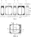
Fig. 3] Fig. 3 is an explanatory drawing illustrating films constituting the pouch. - [
Fig. 4] Fig. 4 is an explanatory drawing illustrating the pouch that is hung while a spout is held. - [
Fig. 5] Fig. 5 is an explanatory drawing illustrating films constituting a pouch according to a second embodiment. - [
Fig. 6] Fig. 6 is an explanatory drawing illustrating the pouch being filled with a content fluid according to the second embodiment. - A
pouch 10 according to a first embodiment of the present invention will be described below in accordance with the accompanying drawings. - As illustrated in
Figs. 1 and2 , thepouch 10 is configured to contain a content fluid, e.g., drinking water or a liquid detergent and includes apouch body 20 formed into a bag from a flexible resin film, aspout 60 attached to thepouch body 20, and aninner film 70 disposed in thepouch body 20. When being used, displayed, or transported, thepouch 10 is handled while being stored in an outer case (not illustrated). - As illustrated in
Figs. 1 and2 , thepouch body 20 is shaped like a bag by heat-sealing a plurality ofbody films sealing portions 23. Specifically, thepouch body 20 is shaped like a bag by forming the bag-makingsealing portions 23 by heat-sealing a front-side film 30, a back-side film 40, and a pair ofgusset portion films 50 around a contentfluid storage portion 21. In the present embodiment, the pouch is configured as a pouch of a so-called horizontal gusset type withgusset portions 22 formed on both sides of the pouch. - As illustrated in
Fig. 1 , thepouch body 20 includes abody bottom 20a that serves as a bottom when thepouch 10 is placed on a loading surface (not illustrated) in a usage state (drainage standby state) of thepouch 10 from which a content fluid can be drained through thespout 60. - While the
pouch 10 is placed on the flat loading surface (horizontal surface), thebody bottom 20a is a portion where thefilms films body bottom 20a.Fig. 3 illustrates to-be-bent portions films - The
films films - The
films Fig. 3 (andFigs. 4 to 6 ), the heat-sealing regions are illustrated in a dotted pattern. - As illustrated in
Fig. 3 , the front-side film 30 includes first heat-sealingregions 31 to be heat-sealed along with the back-side film 40, second heat-sealingregions 32 to be heat-sealed along with thegusset portion films 50, and third heat-sealingregions 33 to be heat-sealed along with theinner film 70. - As illustrated in
Fig. 3 , the back-side film 40 includes first heat-sealingregions 41 to be heat-sealed along with the front-side film 30, second heat-sealingregions 42 to be heat-sealed along with thegusset portion films 50, and third heat-sealingregions 43 to be heat-sealed along with theinner film 70. - As illustrated in
Fig. 3 , thegusset portion film 50 includes first heat-sealingregions 51 to be heat-sealed along with the front-side film 30 and second heat-sealingregions 52 to be heat-sealed along with the back-side film 40. Furthermore, thegusset portion film 50 has a third heat-sealing region 53 to be heat-sealed along with thespout 60. - The
spout 60 is made of a synthetic resin or the like and is attached to thepouch body 20 so as to serve as an outlet of a content fluid. - In the present embodiment, as illustrated in
Fig. 1 , thespout 60 is fixed to one side of thepouch body 20, specifically, one of the gusset portions 22 (gusset portion films 50) by heat sealing. - As illustrated in
Fig. 1 , thespout 60 is attached to a position that is located at one side (thegusset portion 22, the gusset portion film 50) of thepouch body 20 and closer to thebody bottom 20a than the center in the height direction (the center of thegusset portion film 50 in the longitudinal direction). - As illustrated in
Fig. 2 , the contentfluid storage portion 21 includes afirst storage region 21a and asecond storage region 21b that are separated by theinner film 70. Thespout 60 is attached to the position where thespout 60 communicates with thefirst storage region 21a. - As illustrated in
Figs. 2 and3 , theinner film 70 is formed as a rectangular (or substantially rectangular) and flexible resin film having a heat-sealing layer on at least one surface. Theinner film 70 is disposed in the pouch body 20 (content fluid storage portion 21) while being bent into two at afilm bending portion 70a, which linearly extends along the vertical direction (the longitudinal direction of the inner film 70), with the heat-sealing layer facing outward. - As illustrated in
Fig. 2 , theinner film 70 is installed such that thefilm bending portion 70a (a protrusion thereof), which is formed by bending theinner film 70 into two, faces thefirst storage region 21a. - As a modification, a plurality of
inner films 70 configured thus may be installed. Also in this case, theinner films 70 are each preferably installed with thefilm bending portion 70a (a protrusion thereof) facing thefirst storage region 21a. - As illustrated in
Fig. 3 , theinner film 70 has a first fixingportion 71, which is fixed to a first fixedportion 24 of thepouch body 20, on one end of theinner film 70 in the longitudinal direction and asecond fixing portion 72, which is fixed to a second fixedportion 25 of thepouch body 20, on the other end of theinner film 70 in the longitudinal direction, the second fixedportion 25 being opposed to the first fixedportion 24 with the contentfluid storage portion 21 interposed therebetween. - As illustrated in
Figs. 1 and3 , the first fixingportion 71 is disposed between the front-side film 30 and the back-side film 40 and is heat-sealed along with the front-side film 30 and the back-side film 40 while the heat-sealing layer of the first fixingportion 71 in the bag-makingsealing portion 23 on the bottom side of thepouch 10 is bent into two so as to face the heat-sealing layer of the front-side film 30 and the heat-sealing layer of the back-side film 40. In the present embodiment, as illustrated inFig. 1 , the first fixingportion 71 is formed at thebody bottom 20a, and a part of the bag-makingsealing portion 23 on the bottom side of thepouch 10 serves as the first fixedportion 24 of thepouch body 20. - As illustrated in
Figs. 1 and3 , the second fixingportion 72 is disposed between the front-side film 30 and the back-side film 40 and is heat-sealed along with the front-side film 30 and the back-side film 40 while the heat-sealing layer of the second fixingportion 72 in the bag-makingsealing portion 23 on the top side of thepouch 10 is bent into two so as to face the heat-sealing layer of the front-side film 30 and the heat-sealing layer of the back-side film 40. In the present embodiment, as illustrated inFig. 1 , a part of the bag-makingsealing portion 23 on the top side of thepouch 10 serves as the second fixedportion 25 of thepouch body 20. - At the first fixing
portion 71 and the second fixingportion 72, the inner sides of theinner film 70 bent into two are also heat-sealed. For example, a heat-sealing layer is provided on each surface of theinner film 70 or theinner film 70 is provided as a single film made of a heat-sealing material, enabling heat-sealing between the inner sides of theinner film 70. - As illustrated in
Fig. 3 , theinner film 70 has athird fixing portion 73, which is fixed to a third fixedportion 26 of thepouch body 20, on one end of theinner film 70 in the width direction and a fourth fixingportion 74, which is fixed to a fourth fixedportion 27 of thepouch body 20, on the other end of theinner film 70 in the width direction, the fourth fixedportion 27 being opposed to the third fixedportion 26 with the contentfluid storage portion 21 interposed therebetween. - As illustrated in
Fig. 2 , the third fixingportion 73 is disposed with the heat-sealing layer opposed to the heat-sealing layer on the inner side of the front-side film 30, and is heat-sealed along with the inner side of the front-side film 30. In the present embodiment, a part of the inner side of the front-side film 30 serves as the third fixedportion 26 of thepouch body 20. - As illustrated in
Fig. 2 , the fourth fixingportion 74 is disposed with the heat-sealing layer opposed to the heat-sealing layer on the inner side of the back-side film 40 and is heat-sealed along with the inner side of the back-side film 40. In the present embodiment, a part of the inner side of the back-side film 40 serves as the fourth fixedportion 27 of thepouch body 20. - As illustrated in
Fig. 1 , theinner film 70 further includes aninner placement portion 75 that is a region formed inside the fixingportions 71 to 74 and is disposed in thepouch body 20 without being fixed to thepouch body 20. - As illustrated in
Figs. 2 and3 , theinner film 70 has a plurality of film throughportions 76 that are formed like holes passing through the film in the thickness direction. - In the present embodiment, as illustrated in
Fig. 3 , the film throughportions 76 include a first film-throughportion 76a formed over the first fixingportion 71 and theinner placement portion 75, second film-throughportions 76b formed on the second fixingportion 72, and a plurality of (two) inner film-throughportions 76c formed on theinner placement portion 75. - A part of the first film-through
portion 76a and the inner film-throughportions 76c serve as portions that pass a content fluid and gas such as air between thefirst storage region 21a and thesecond storage region 21b. - A part formed on the first fixing
portion 71 in the first film-throughportion 76a is disposed on thebody films sealing portion 23. - As illustrated in
Fig. 1 , the second film-throughportion 76b is formed by collectively forming throughholes 28 in a portion where thefilms sealing portion 23 on the top side of thepouch 10. The through holes 28 serve as holding holes for holding thepouch 10 with a hand or fingers of a user. - At least one of the film through
portions 76 is formed over thefilm bending portion 70a. In the present embodiment, as illustrated inFigs. 2 and3 , the first film-throughportion 76a and the inner film-throughportions 76c are formed over thefilm bending portion 70a. - As illustrated in
Figs. 2 and3 , theinner film 70 has a to-be-bent portion 77 that is bent at thebody bottom 20a (in other words, on the loading surface) when thepouch 10 containing a content fluid is placed on the loading surface with thebody bottom 20a placed at the bottom of the pouch. - The to-
be-bent portion 77 is a linear portion extending along the horizontal direction (the width direction of the inner film 70) as illustrated inFigs. 2 and3 . - At least one of the film through
portions 76 is formed over the to-be-bent portion 77. In the present embodiment, as illustrated inFigs. 2 and3 , the first film-throughportion 76a is formed over the to-be-bent portion 77. - The
inner film 70 has a fluid-level contact portion 78 that comes into contact with the fluid level of a content fluid when the sealedpouch 10 containing the content fluid is placed on the loading surface with thebody bottom 20a placed at the bottom of the pouch. - The fluid-
level contact portion 78 is a linear portion extending along the horizontal direction (the width direction of the inner film 70) as illustrated inFig. 3 . - At least one of the film through
portions 76 is formed over the fluid-level contact portion 78. In the present embodiment, upper one of the two inner film-throughportions 76c is formed over the fluid-level contact portion 78. - During the manufacturing of the
pouch 10, theinner film 70 having the first film-throughportion 76a and the second film-throughportions 76c is prepared, theinner film 70 is heat-sealed along with thebody films portion 76b (through hole 28) is formed through thefilms - In the
pouch 10 of the present embodiment obtained thus, the first film-throughportion 76a formed on theinner film 70 is overlapped on thebody films sealing portion 23. - In this way, the first film-through
portion 76a is formed at a position overlapping thebody films sealing portions 23, so that the formation position of the first film-throughportion 76a on theinner film 70 can be confirmed from the outside by using a change of the thickness of the bag-makingsealing portion 23. Even if the formation positions of the inner film-throughportions 76c disposed in thepouch body 20 cannot be confirmed from the outside on the basis of the formation position of the first film-throughportion 76a, the formation positions of the inner film-throughportions 76c disposed in thepouch body 20 can be estimated. - Moreover, the
spout 60 is attached to a position that is located at one side of thepouch body 20 and closer to thebody bottom 20a than a center in a height direction, and the first fixingportion 71 having the first film-throughportion 76a is formed at thebody bottom 20a. Thus, when filling thepouch body 20 with a content fluid through thespout 60 while holding thespout 60 to hang thepouch 10, gas such as air in thepouch body 20 can be passed through the first film-throughportion 76a, so that gas such as air in thepouch body 20 can be properly discharged to the outside. In other words, in a state in which thespout 60 is held to hang thepouch 10, as illustrated inFig. 4 , the first fixingportion 71 having the first film-throughportion 76a is placed upward. Thus, when thepouch body 20 is filled with a content fluid L through thespout 60, gas A such as air in thepouch body 20 can be smoothly passed through the first film-throughportion 76a and can be discharged to the outside from thespout 60. In the filling method of the content fluid inFig. 4 , the content fluid is supplied into thepouch 10 in a folded state (not expanded, the front-side film 30 and the back-side film 40 in contact with each other), the content fluid may be supplied into thepouch 10 unfolded in advance. - Referring to
Figs. 5 and 6 , apouch 10 according to a second embodiment of the present invention will be described below. The second embodiment is completely identical to the first embodiment except for some configurations, and thus a description of configurations other than differences is omitted. - In the second embodiment, as illustrated in
Fig. 5 , one of second film-throughportions 76b is formed over asecond fixing portion 72 and aninner placement portion 75. - The second film-through portion formed over the second fixing
portion 72 and theinner placement portion 75 is overlapped on thebody films sealing portions 23. - In the second embodiment, as illustrated in
Fig. 6 , thepouch 10 in an unfolded state (expanded, the front-side film 30 and the back-side film 40 separated from each other) is placed with asecond storage region 21b located under afirst storage region 21a (more specifically, the orientation of thepouch 10 is kept such that onegusset portion film 50 having aspout 60 is directed upward while the othergusset portion film 50 is directed downward) . In this state, one of inner film-throughportions 76c is disposed below thespout 60. - A filling method for filling, in the
pouch 10 of the second embodiment, a content fluid into thepouch 10 will be described below. - First, as illustrated in
Fig. 6 , thepouch 10 in an unfolded state is placed with thesecond storage region 21b located under thefirst storage region 21a, and then a filling nozzle N is vertically inserted into thesecond storage region 21b from the outside of thepouch 10 through a spout outlet (not illustrated), which is formed in thespout 60, and the inner film-throughportion 76c. - Subsequently, as illustrated in
Fig. 6 , a content fluid discharged from the filling nozzle N is supplied into thepouch 10, thereby filling thepouch 10 with the content fluid. - When the unfolded
pouch 10 is filled with a content fluid, a substantial amount of gas (air) in thesecond storage region 21b needs to be moved to thefirst storage region 21a to suppress the foaming of the content fluid in thepouch 10 while the content fluid is supplied into thesecond storage region 21b. In the second embodiment, gas in thesecond storage region 21b can be moved to thefirst storage region 21a through the first film-throughportion 76a and the second film-throughportions 76b (and inner film-throughportions 76c) while a content fluid from the filling nozzle N is supplied into thesecond storage region 21b. This can properly suppress the foaming of the content fluid in thepouch 10. - In the second embodiment, as a content fluid is supplied, the filling nozzle N is moved upward according to the height of the fluid level of the content fluid in the
pouch 10. The filling nozzle N may be kept at the same position during the filling of the content fluid. - The embodiments of the present invention were described in detail. The present invention is not limited to the specific embodiments, and the design can be changed in various ways without departing from the present invention described in the claims. Furthermore, the configurations of the embodiments and modifications, which will be described later, may be optionally combined to configure the
pouch 10. - For example, in the foregoing embodiments, the
pouch 10 stored in an outer case (not illustrated) is handled when being used, displayed, or transported. Thepouch 10 may be used, displayed, or transported without being stored in an outer case (not illustrated). - The specific configurations of the
films 30 to 50 constituting thepouch body 20 may include a single heat-sealing layer or any layers stacked on a heat-sealing layer if a heat-sealing layer made of olefins such as low-density polyethylene and polypropylene or polyesters such as PET (polyethylene terephthalate) is formed on at least one surface. The stacked layers may be made of any materials. The layers may be optionally formed by stacking known polyesters such as PET and PBT (polybutylene terephthalate), polypropylene, polyamide, polyethylene, and aluminum foil. - In the foregoing embodiments, the
pouch body 20 is composed of four body films: the front-side film 30, the back-side film 40, and the pair ofgusset portion films 50. The specific configuration of thepouch body 20, for example, the number of body films constituting thepouch body 20 is not limited thereto. - In the foregoing embodiments, the
pouch body 20 is formed as a pouch of a so-called horizontal gusset type with thegusset portions 22 formed on both sides. Thepouch body 20 may have any specific configuration, for example, a pouch of a so-called bottom gusset type with asingle gusset portion 22 or a pouch having threegusset portions 22 on both sides and the bottom. - In the foregoing embodiments, the
spout 60 is attached to the gusset portion 22 (gusset portion film 50). The specific arrangement of thespout 60 is not limited thereto, and thespout 60 may be freely arranged. Alternatively, thepouch 10 may be configured with an outlet formed by cutting a part of thepouch body 20 in the absence of thespout 60. - The method of fixing the
inner film 70 to thepouch body 20 is not limited to the heat-sealing. Theinner film 70 may be fixed by any method, for example, bonding with an adhesive. - In the foregoing embodiments, all the film through
portions 76 are formed like holes passing through theinner film 70 in the film thickness direction. At least one of the film throughportions 76 may be formed like a notch reaching the outer edge of theinner film 70. - Moreover, the specific number, arrangement, shapes of the film through portions 76 (the first film-through
portion 76a, the second film-throughportions 76b, the inner film-throughportions 76c) are not limited. - In the foregoing embodiments, the first film-through
portion 76a is formed over the first fixingportion 71 and theinner placement portion 75. At least a part of the first film-throughportion 76a needs to be formed in the first fixingportion 71, and the first film-throughportion 76a may be entirely formed in the first fixingportion 71. - The second film-through
portions 76b does not always need to be formed. - In the foregoing embodiments, the inner film-through
portions 76c do not overlap the body film in the bag-makingsealing portion 23. The inner film-throughportions 76c may be formed to overlap the body film in the bag-makingsealing portion 23. - The
film bending portion 70a is formed on theinner film 70. Thefilm bending portion 70a does not always need to be formed on theinner film 70. - In the foregoing embodiments, the first film-through
portion 76a are formed over the to-be-bent portion 77. Other film through portions 76 (e.g., the inner film-throughportions 76c) may be formed over the to-be-bent portion 77. - In the foregoing embodiments, the inner film-through
portions 76c are formed over the fluid-level contact portion 78. Other film through portions 76 (e.g., the second film-throughportions 76b) may be formed over the fluid-level contact portion 78. - In the foregoing embodiments, the first fixed
portion 24 of thepouch body 20 is a part of the bag-makingsealing portion 23 on the bottom side, and the second fixedportion 25 is a part of the bag-makingsealing portion 23 on the top side. The specific positions of the first fixedportion 24 and the second fixedportion 25 may be any positions in the positional relationship where the fixed portions are opposed to each other with the contentfluid storage portion 21 interposed therebetween. The positions can be optionally changed for a desired effect of suppressing the body expansion of thepouch body 20. - Likewise, in the foregoing embodiments, the third fixed
portion 26 of thepouch body 20 is a part of the inner side of the front-side film 30, and the fourth fixedportion 27 is a part of the inner side of the back-side film 40. The specific positions of the third fixedportion 26 and the fourth fixedportion 27 may be any positions in the positional relationship where the fixed portions are opposed to each other with the contentfluid storage portion 21 interposed therebetween. - Moreover, the specific number and arrangement of the
inner films 70 and the pattern of fixation to thefilms portion 71 and the second fixingportion 72 are provided. - The
third fixing portion 73 and the fourth fixingportion 74 may be absent on theinner film 70. In other words, theinner film 70 may be fixed to thepouch body 20 only with the first fixingportion 71 and the second fixingportion 72. - In the present specification, terms such as "top", "bottom", and "side" that indicate the upper-lower relationship are used. These terms do not limit the orientation of the
pouch 10 installed when being displayed or transported. For example, when being displayed or transported, thepouch 10 may be installed with one side or the top placed at the bottom of the pouch. -
- 10
- Pouch
- 20
- Pouch body
- 20a
- Body bottom
- 21
- Content fluid storage portion
- 21a
- First storage region
- 21b
- Second storage region
- 22
- Gusset portion
- 23
- Bag-making sealing portion
- 24
- First fixed portion
- 25
- Second fixed portion
- 26
- Third fixed portion
- 27
- Fourth fixed portion
- 28
- Through hole
- 30
- Front-side film (body film)
- 31
- First heat-sealing region
- 32
- Second heat-sealing region
- 33
- Third heat-sealing region
- 34
- To-be-bent portion
- 40
- Back-side film (body film)
- 41
- First heat-sealing region
- 42
- Second heat-sealing region
- 43
- Third heat-sealing region
- 44
- To-be-bent portion
- 50
- Gusset portion film (body film)
- 51
- First heat-sealing region
- 52
- Second heat-sealing region
- 53
- Third heat-sealing region
- 54
- To-be-bent portion
- 60
- Spout
- 70
- Inner film
- 70a
- Film bending portion
- 71
- First fixing portion
- 72
- Second fixing portion
- 73
- Third fixing portion
- 74
- Fourth fixing portion
- 75
- Inner placement portion
- 76
- Film through portion
- 76a
- First film-through portion
- 76b
- Second film-through portion
- 76c
- Inner film-through portion
- 77
- To-be-bent portion
- 78
- Fluid-level contact portion
Claims (11)
- A pouch having a gusset portion,the pouch comprising a pouch body formed like a bag by heat-sealing a plurality of body films to form a bag-making sealing portion, and an inner film disposed in the pouch body,wherein the pouch body includes a content fluid storage portion, and a first fixed portion and a second fixed portion that are opposed to each other with the content fluid storage portion interposed between the fixed portions,the inner film includes a first fixing portion fixed to the first fixed portion, a second fixing portion fixed to the second fixed portion, an inner placement portion that is disposed in the pouch body without being fixed to the pouch body, and a plurality of film through portions that are formed like holes penetrating in a film thickness direction or notches,the plurality of film through portions include a first film-through portion at least partially formed on the first fixing portion, and an inner film-through portion formed on the inner placement portion, andthe first film-through portion is overlapped on the body film in the bag-making sealing portion.
- The pouch according to claim 1, wherein the first film-through portion is formed over the first fixing portion and the inner placement portion.
- The pouch according to claim 2, further comprising a spout attached to the pouch body,wherein the pouch body includes a body bottom,the spout is attached to a position that is located at one side of the pouch body and closer to the body bottom than a center in a height direction, andthe first fixing portion is formed at the body bottom.
- The pouch according to any one of claims 1 to 3, wherein the plurality of film through portions include a second film-through portion at least partially formed on the second fixing portion, and
the second film-through portion is overlapped on the body film in the bag-making sealing portion. - The pouch according to any one of claims 1 to 4, further comprising a spout attached to the pouch body,wherein the pouch body includes a body bottom,the inner film has a to-be-bent portion that is bent at the body bottom when the pouch containing a content fluid is placed on a loading surface with the body bottom placed at a bottom of the pouch, andat least one of the film-through portions is formed over the to-be-bent portion.
- The pouch according to any one of claims 1 to 5, further comprising a spout attached to the pouch body,wherein the pouch body includes a body bottom,the content fluid storage portion includes a first storage region and a second storage region that are separated by the inner film,the inner film has a fluid-level contact portion that comes into contact with a fluid level of a content fluid when the sealed pouch containing the content fluid is placed on the loading surface with the body bottom placed at the bottom of the pouch, andat least one of the film-through portions is formed over the fluid-level contact portion.
- The pouch according to any one of claims 1 to 6, wherein the inner film is configured as a resin film having a heat-sealing layer, and
the first fixing portion is disposed between the two body films and is heat-sealed to the two body films in the bag-making sealing portion so as to be fixed to the pouch body. - The pouch according to claim 7, wherein the inner film is configured as a resin film having a heat-sealing layer and is bent into two with the heat-sealing layer facing outward, and
the first fixing portion and the second fixing portion that are bent into two are disposed between the two body films and are heat-sealed to the two body films in the bag-making sealing portion. - The pouch according to claim 8, further comprising a spout attached to the pouch body,wherein the provided inner film is at least one inner film,the content fluid storage portion includes a first storage region and a second storage region that are separated by the inner film,the spout is attached to a position where the spout communicates with the first storage region, andthe inner films are all installed such that the film bending portion faces the first storage region, the film bending portion being formed by bending the inner film into two.
- The pouch according to claim 9, wherein at least one of the film-through portions is formed over the film bending portion.
- A filling method for filling the pouch according to any one of claims 1 to 10 with a content fluid,wherein the plurality of film through portions include the second film-through portion at least partially formed on the second fixing portion,the second film-through portion is overlapped on the body film in the bag-making sealing portion,the first film-through portion is formed over the first fixing portion and the inner placement portion,the second film-through portion is formed over the second fixing portion and the inner placement portion,the content fluid storage portion includes the first storage region and the second storage region that are separated by the inner film, andthe spout having a spout outlet is attached to a position where the spout communicates with the first storage region of the pouch body,the method comprising, with the second storage region located under the first storage region, inserting a filling nozzle into the second storage region from outside of the pouch through the spout outlet and the inner film-through portion; and moving gas in the second storage region into the first storage region through the first film-through portion and the second film-through portion while supplying the content fluid from the filling nozzle into the second storage region during the filling of the content fluid.
Applications Claiming Priority (2)
| Application Number | Priority Date | Filing Date | Title |
|---|---|---|---|
| JP2020079661 | 2020-04-28 | ||
| PCT/JP2021/006250 WO2021220591A1 (en) | 2020-04-28 | 2021-02-19 | Pouch and filling method |
Publications (2)
| Publication Number | Publication Date |
|---|---|
| EP4144663A1 true EP4144663A1 (en) | 2023-03-08 |
| EP4144663A4 EP4144663A4 (en) | 2024-07-10 |
Family
ID=78331933
Family Applications (1)
| Application Number | Title | Priority Date | Filing Date |
|---|---|---|---|
| EP21797316.3A Pending EP4144663A4 (en) | 2020-04-28 | 2021-02-19 | BAGS AND FILLING METHODS |
Country Status (6)
| Country | Link |
|---|---|
| US (1) | US12077358B2 (en) |
| EP (1) | EP4144663A4 (en) |
| JP (1) | JP6984798B1 (en) |
| CN (1) | CN115397741B (en) |
| TW (1) | TWI871460B (en) |
| WO (1) | WO2021220591A1 (en) |
Families Citing this family (4)
| Publication number | Priority date | Publication date | Assignee | Title |
|---|---|---|---|---|
| JP7476868B2 (en) * | 2021-11-22 | 2024-05-01 | 東洋製罐株式会社 | Pouch with spout |
| WO2023090393A1 (en) * | 2021-11-22 | 2023-05-25 | 東洋製罐株式会社 | Spouted pouch |
| JP7859201B2 (en) * | 2022-06-01 | 2026-05-15 | 王子ホールディングス株式会社 | Bag-making materials |
| JP2024044526A (en) * | 2022-09-21 | 2024-04-02 | 東洋製罐株式会社 | Pouch with gusset |
Family Cites Families (25)
| Publication number | Priority date | Publication date | Assignee | Title |
|---|---|---|---|---|
| DE3711165A1 (en) * | 1987-04-02 | 1988-10-20 | Stiegler Maschf Gmbh | METHOD FOR PRODUCING CARRYING BAGS FROM PLASTIC FILM WITH SIDE SEAM |
| US4904093A (en) * | 1988-08-24 | 1990-02-27 | The Dow Chemical Comapny | Gussetted plastic bags having relief seals and method of making same |
| JPH09238746A (en) * | 1996-03-01 | 1997-09-16 | Fujikura Rubber Ltd | Bag for carrying liquid |
| JP2000272670A (en) * | 1999-03-23 | 2000-10-03 | Kiyoshi Takaura | Airtight bag that keeps a flat shape |
| EP1272399B1 (en) * | 2000-04-11 | 2005-11-30 | The Coca-Cola Company | Beverage pouch and process for the manufacture and use of such a pouch |
| JP2004026251A (en) * | 2002-06-27 | 2004-01-29 | Fujimori Kogyo Co Ltd | Self-contained packaging bags |
| US7458195B2 (en) * | 2005-01-14 | 2008-12-02 | Frito-Lay North America, Inc. | Method for making a multi-compartment microwavable package having a permeable wall between compartments |
| JP4768550B2 (en) * | 2006-09-04 | 2011-09-07 | 東洋製罐株式会社 | Pouch with spout |
| US20080240622A1 (en) * | 2007-03-30 | 2008-10-02 | Gary Michael Bell | Bag construction with flat bottom having removable layer |
| US8944684B2 (en) * | 2007-03-30 | 2015-02-03 | Ampac Holdings Llc | Bag construction with side gussets |
| JP5315022B2 (en) * | 2008-11-20 | 2013-10-16 | イーエヌ大塚製薬株式会社 | Fluid container |
| US20100172600A1 (en) * | 2009-01-06 | 2010-07-08 | The Coca-Cola Company | Flexible container and method of making the same |
| ES2413191T3 (en) * | 2009-09-25 | 2013-07-15 | Mondi Halle Gmbh | Flat bottom bag formed of a plastic sheet suitable for heat sealing and manufacturing process |
| JP5707118B2 (en) * | 2010-12-09 | 2015-04-22 | 藤森工業株式会社 | Container for filling |
| JP5992200B2 (en) * | 2012-05-10 | 2016-09-14 | 株式会社細川洋行 | Spouted gusset bag |
| AU2014375296A1 (en) * | 2013-12-30 | 2016-07-07 | Pernod Ricard Sa | Beverage dispensing module and flexible pouch |
| WO2015111736A1 (en) * | 2014-01-24 | 2015-07-30 | 株式会社細川洋行 | Gusset bag, method for producing gusset bag, and method for joining laminate |
| US20150274392A1 (en) * | 2014-04-01 | 2015-10-01 | Kv Lock Llc | Two handled spouted plastic gusseted pouch for containing fluid and method for making |
| GB2553627B (en) * | 2014-11-03 | 2018-09-19 | Pernod Ricard | Flexible pouch for a beverage |
| CN204871971U (en) * | 2015-08-24 | 2015-12-16 | 杭州扬中科技有限公司 | Expandable plastic bag |
| JP7170465B2 (en) * | 2018-08-30 | 2022-11-14 | 株式会社細川洋行 | Gusseted bags and bag-in-box |
| JP6650501B2 (en) | 2018-09-26 | 2020-02-19 | 株式会社バンダイ | Motion-responsive toys and main toys |
| CN209480302U (en) * | 2019-01-30 | 2019-10-11 | 江西锦泰塑业有限公司 | Environment protection type package bag |
| EP3925901A4 (en) * | 2019-02-15 | 2023-03-01 | Toyo Seikan Co., Ltd. | BAGS AND METHOD OF MAKING BAGS |
| JP7371332B2 (en) * | 2019-02-15 | 2023-10-31 | 東洋製罐株式会社 | Gusseted pouch and method for manufacturing gusseted pouch |
-
2021
- 2021-02-19 JP JP2021538096A patent/JP6984798B1/en active Active
- 2021-02-19 CN CN202180013743.0A patent/CN115397741B/en active Active
- 2021-02-19 EP EP21797316.3A patent/EP4144663A4/en active Pending
- 2021-02-19 WO PCT/JP2021/006250 patent/WO2021220591A1/en not_active Ceased
- 2021-04-09 TW TW110112839A patent/TWI871460B/en active
-
2022
- 2022-10-27 US US17/974,992 patent/US12077358B2/en active Active
Also Published As
| Publication number | Publication date |
|---|---|
| TWI871460B (en) | 2025-02-01 |
| JP6984798B1 (en) | 2021-12-22 |
| CN115397741A (en) | 2022-11-25 |
| WO2021220591A1 (en) | 2021-11-04 |
| US12077358B2 (en) | 2024-09-03 |
| EP4144663A4 (en) | 2024-07-10 |
| CN115397741B (en) | 2023-10-20 |
| TW202208247A (en) | 2022-03-01 |
| JPWO2021220591A1 (en) | 2021-11-04 |
| US20230047940A1 (en) | 2023-02-16 |
Similar Documents
| Publication | Publication Date | Title |
|---|---|---|
| US12077358B2 (en) | Pouch and filling method | |
| US12275569B2 (en) | Spouted pouch | |
| JP7371332B2 (en) | Gusseted pouch and method for manufacturing gusseted pouch | |
| JP2009524557A (en) | Packaging bag with spout | |
| US20070267414A1 (en) | Package | |
| US20250206504A1 (en) | Gusseted pouch | |
| US11772868B2 (en) | Pouch and pouch manufacturing method | |
| CN112638784A (en) | Container comprising a sheet for a container | |
| JP2006111310A (en) | Pouch container with spout | |
| JP7666172B2 (en) | Pouches and pouch cases | |
| TWI915044B (en) | Horizontal support bag | |
| JP7505475B2 (en) | Pouch with spout | |
| JP6651740B2 (en) | Gazette bag with handle | |
| JP7031146B2 (en) | Fitting structure of flexible packaging bag and refillable container and their set | |
| JP7762496B2 (en) | Gusseted pouch | |
| JP7852257B2 (en) | Pouch with spout and spout | |
| JP2024158831A (en) | Horizontal gusset pouch | |
| JP2025018683A (en) | Packaging container and manufacturing method | |
| JP2023148478A (en) | Packaging containers and packages | |
| JP2005289390A (en) | Two-chamber bag with easy opening | |
| JP2022029763A (en) | Pouch with spout, pouched case, and pouch storage method | |
| JP2020200059A (en) | Pouch intermediate body and pouch filling method | |
| JP2026084731A (en) | Standing pouch | |
| JP2023078504A5 (en) | ||
| JP2022171344A (en) | pouch container |
Legal Events
| Date | Code | Title | Description |
|---|---|---|---|
| STAA | Information on the status of an ep patent application or granted ep patent |
Free format text: STATUS: THE INTERNATIONAL PUBLICATION HAS BEEN MADE |
|
| PUAI | Public reference made under article 153(3) epc to a published international application that has entered the european phase |
Free format text: ORIGINAL CODE: 0009012 |
|
| STAA | Information on the status of an ep patent application or granted ep patent |
Free format text: STATUS: REQUEST FOR EXAMINATION WAS MADE |
|
| 17P | Request for examination filed |
Effective date: 20221107 |
|
| AK | Designated contracting states |
Kind code of ref document: A1 Designated state(s): AL AT BE BG CH CY CZ DE DK EE ES FI FR GB GR HR HU IE IS IT LI LT LU LV MC MK MT NL NO PL PT RO RS SE SI SK SM TR |
|
| DAV | Request for validation of the european patent (deleted) | ||
| DAX | Request for extension of the european patent (deleted) | ||
| A4 | Supplementary search report drawn up and despatched |
Effective date: 20240607 |
|
| RIC1 | Information provided on ipc code assigned before grant |
Ipc: B65D 33/38 20060101ALI20240603BHEP Ipc: B65D 30/22 20060101ALI20240603BHEP Ipc: B65D 30/20 20060101ALI20240603BHEP Ipc: B65D 30/16 20060101ALI20240603BHEP Ipc: B65D 77/06 20060101AFI20240603BHEP |